

PART OBSOLETE - EOL18
Bulletin I2718 rev. E 05/02
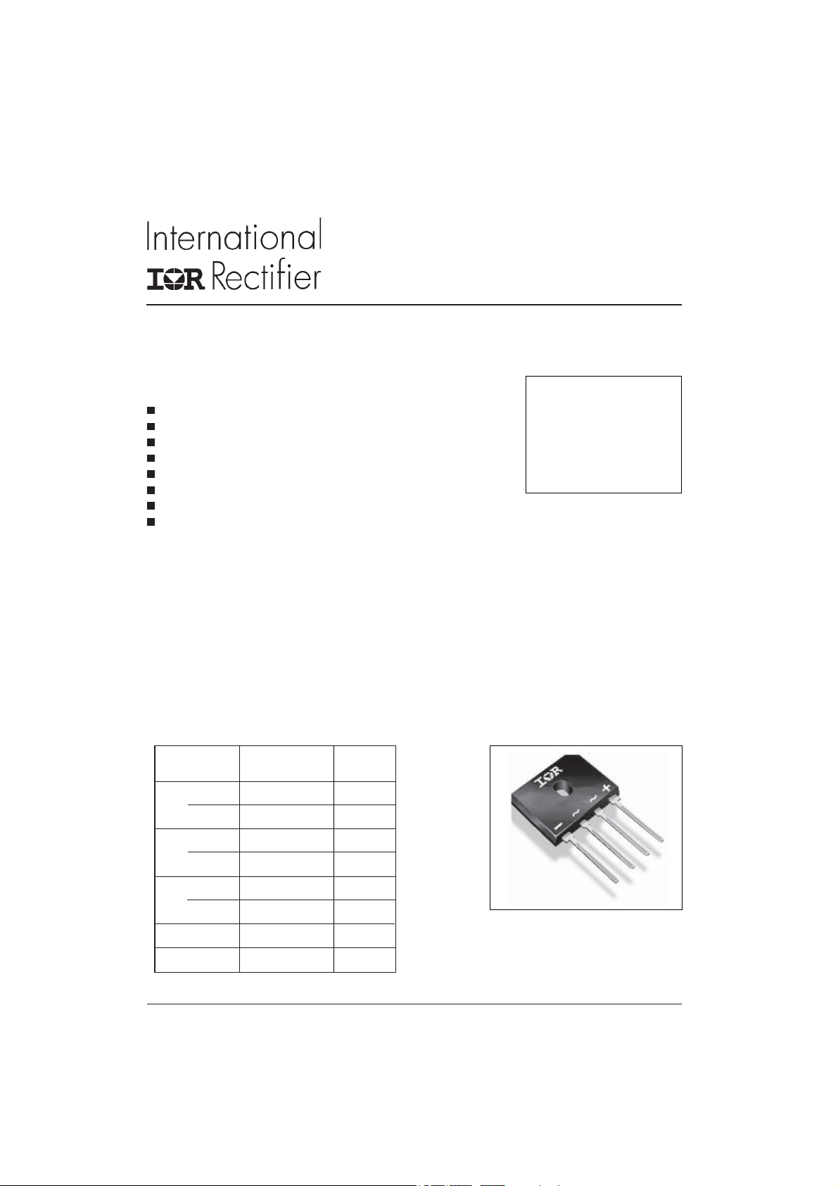
6GBU Series
6.0 Amps Single Phase Full Wave
Features
Diode chips are glass passivated
Suitable for Universal hole mounting
Easy to assemble & install on P.C.B.
High Surge Current Capability
High Isolation between terminals and molded case (1500 V
Lead free terminals solderable as per MIL-STD-750 Method 2026
Terminals suitable for high temperature soldering at 260°C for 8-10 secs
UL E160375 approved
Description
These GBU Series of Single Phase Bridges consist
of four glass passivated silicon junction connected
as a Full Wave Bridge. These four junctions are
encapsulated by plastic molding technique. These
Bridges are mainly used in Switch Mode power
supply and in industrial and consumer equipment.
RMS
)
Bridge Rectifier
I
= 6A
O(AV)
V
= 50/ 800V
RRM
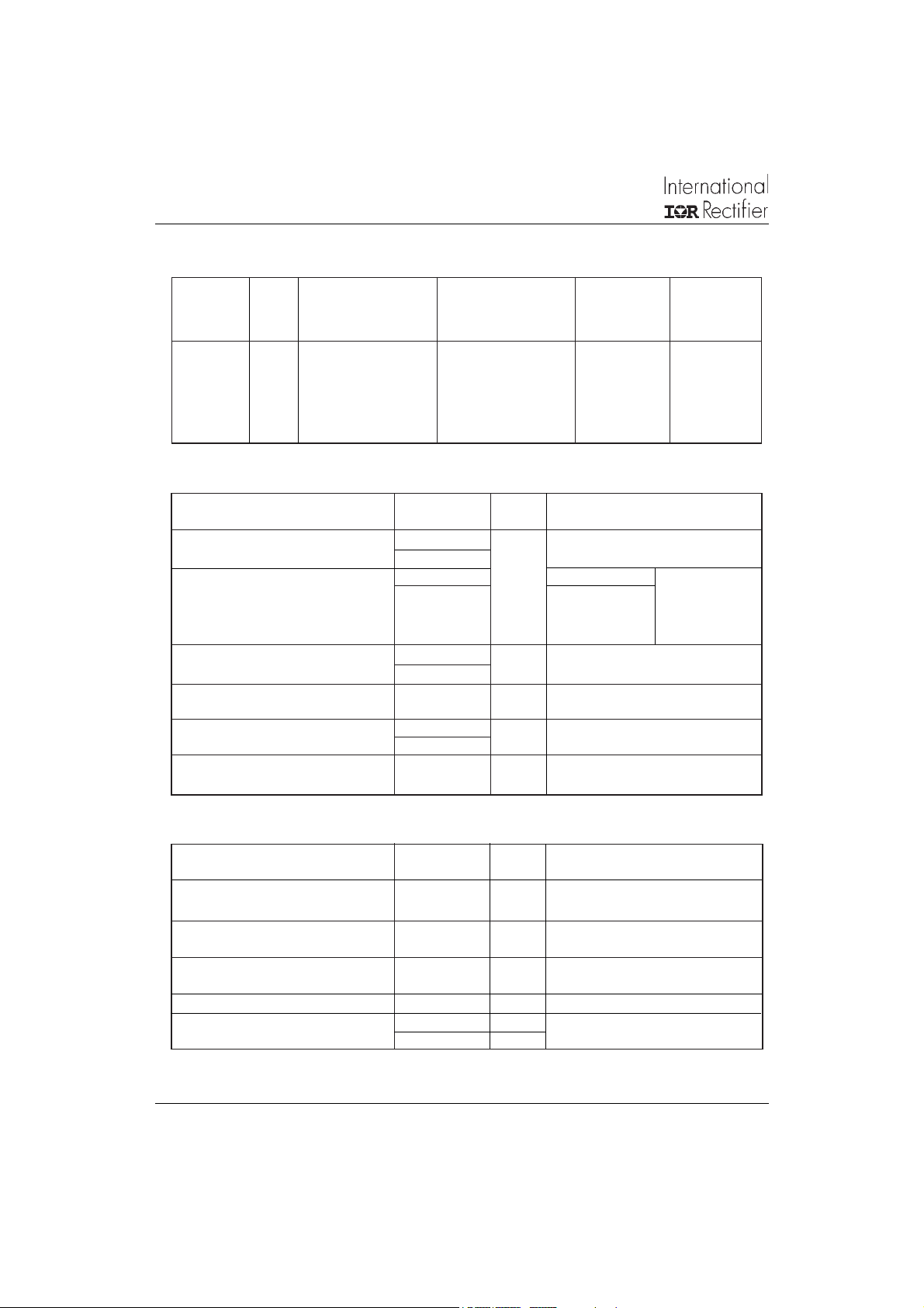
Major Ratings and Characteristics
Parameters 6GBU Units
I
O
@ T
C
I
@ 50Hz 175 A
FSM
@ 60Hz 182 A
I2t @ 50Hz 154 A2s
@ 60Hz 138 A2s
V
range 50 to 800 V
RRM
T
J
6A
100 °C
- 55 to 150
www.irf.com
6GBU
o
C
1
6GBU Series
Bulletin I2718 rev. E 05/01
ELECTRICAL SPECIFICATIONS
Voltage Ratings
Voltage V
Type number Code peak rev. voltage voltage @ rated V
6GBU 005 50 35 5 400
01 100 70 5 400
02 200 140 5 400
04 400 280 5 400
06 600 420 5 400
08 800 560 5 400
, max repetitive V
RRM
TJ = T
max. T
J
V V µA µA
, max RMS I
RMS
= T
max. T
J
J
max. I
RRM
= 25°C T
J
RRM
Forward Conduction
Parameters 6GBU Unit Conditions
I
Maximum DC output current 6.0 A TC = 100°C, Resistive & inductive load
O
I
Maximum peak, one-cycle 175 t = 10ms
FSM
non-repetitive surge current,
following any rated load condition 182 t = 8.3ms TJ = 150°C
and with rated V
reapplied
RRM
I2t Maximum I2t for fusing, 154 A2s t = 10ms
initial TJ = TJ max 138 t = 8.3ms
V
Maximum peak forward voltage 1.0 V TJ = 25 oC, IFM = 6A
FM
per diode
I
Typical peak reverse leakage 5.0 µA TJ = 2 5 oC, 100% V
RM
curren t per diode 400 TJ = 150 oC, 100% V
V
Maximum repetitive peak 50 to 800 V
RRM
reverse voltage range
4.8 TC = 100°C, Capacitive load
RRM
RRM
max.
RRM
@ rated V
= 150°C
J
RRM
Thermal and Mechanical Specifications
Parameters 6GBU Unit Conditions
T
Operating and storage -55 to 150
J
T
temperature range
stg
R
Max. thermal resistance 2.2 °C/ W DC rated current through bridge (1)
thJC
junction to case
R
Thermal resistance, 7.4 °C/ W DC rated current through bridge (1)
thJA
junction to ambient
W Approximate weight 4 (0.14) g (oz)
T Mounting Torque 1.0 Nm Bridge to Heatsink
9.0 Lb.in
Note (1): Bridge mounted on Aluminum heat sink of dim 65 x 35 x 1.5mm, use silicon thermal compound heat
transfer and bolt down using 3mm screw
2
o
C
www.irf.com

Ordering Information Table
Device Code
6GBU Series
Bulletin I2718 rev. E 05/02
6 GBU 08
Outline Table
1 2
1 - Bridge current
2 - Basic Part Number
3 - Voltage Code: code x 100 = V
3
RRM
www.irf.com
All dimensions are in millimetres
3

6GBU Series
Bulletin I2718 rev. E 05/01
160
150
6GBU Series
140
130
120
110
180˚
(Rect)
180˚
(Sine)
100
90
Maximum Allowable Case Temperature (°C)
01234567
Average Forward Current (A)
Fig. 1 - Current Ratings Characteristics
12
180˚
10
8
(Sine)
180˚
(Rect)
6
4
6GBU Series
T = 150˚C
2
0
Maximum Average Forward Power Loss (W)
0123456
Average Forward Current (A)
Fig. 3 - Total Power Loss Characteristics
J
1000
100
10
T = 25˚C
J
T = 150˚C
J
1
Instantaneous Forward Current (A)
0.1
0.5 1 1.5 2 2.5 3
Instantaneous Forward Voltage (V)
Fig. 2 - Forward Voltage Drop Characteristics
200
At Any Rated Load Condition And With
Rated Vrrm Applied Following Surge.
180
160
6GBU Series
Initial Tj = 150˚C
@ 60 Hz 0.0083 s
@ 50 Hz 0.0100 s
140
120
100
80
60
6GBU Series
40
Peak Half Sine Wave Forward Current (A)
1 10 100
Number of Equal Amplitude Half Cycle Current Pulses (N)
Fig. 4 - Maximum Non-Repetitive Surge Current
4
www.irf.com

6GBU Series
Bulletin I2718 rev. E 05/02
Data and specifications subject to change without notice.
This product has been designed and qualified for Multiple Level.
Qualification Standards can be found on IR's Web site.
IR WORLD HEADQUARTERS: 233 Kansas St., El Segundo, California 90245, USA Tel: (310) 252-7105
TAC Fax: (310) 252-7309
Visit us at www.irf.com for sales contact information. 05/02
www.irf.com
5
 Loading...