

PD-2.297 rev. A 12/97
30CPQ035
30CPQ040
30CPQ045
SCHOTTKY RECTIFIER 30 Amp
Major Ratings and Characteristics Description/Features
The 30CPQ... center tap Schottky rectifier has been optimized
Characteristics 30CPQ... Units
I
Rectangular 30 A
F(AV)
waveform
V
RRM
@ tp = 5 µs sine 1020 A
I
FSM
VF@ 15 Apk, TJ=125°C 0.50 V
(per leg)
T
J
35/40/45 V
- 55 to 150 °C
for very low forward voltage drop, with moderate leakage. The
proprietary barrier technology allows for reliable operation up to
150° C junction temperature. Typical applications are in
switching power supplies, converters, free-wheeling diodes,
and reverse battery protection.
150° C T
Center tap TO-247 package
High purity, high temperature epoxy encapsulation for
enhanced mechanical strength and moisture resistance
Very low forward voltage drop
High frequency operation
Guard ring for enhanced ruggedness and long term
reliability
operation
J
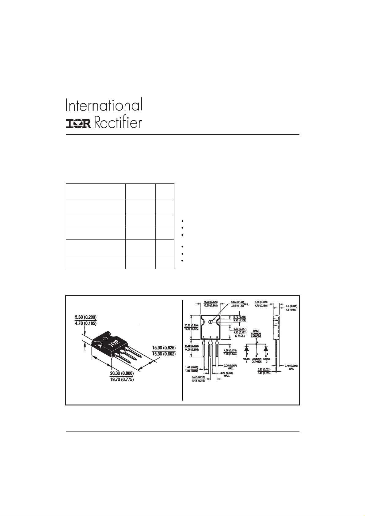
CASE STYLE AND DIMENSIONS
Conforms to JEDEC Outline TO-247AC (TO-3P)
Dimensions in millimeters and inches
1www.irf.com
30CPQ035, 30CPQ040, 30CPQ045
PD-2.297 rev. A 12/97
Voltage Ratings
Part number 30CPQ035 30CPQ040 30CPQ045
VRMax. DC Reverse Voltage (V)
Max. Working Peak Reverse Voltage (V)
V
RWM
35 40 45
Absolute Maximum Ratings
Parameters 30CPQ... Units Conditions
I
Max. Average Forward Current 30 A 50% duty cycle @ TC = 124 °C, rectangular wave form
F(AV)
* See Fig. 5
I
Max. Peak One Cycle Non-Repetitive 1020 5µs Sine or 3µs Rect. pulse
FSM
Surge Current (Per Leg) * See Fig. 7 26 5 10ms Sine or 6ms Rect. pulse
EASNon-Repetitive Avalanche Energy 20 mJ T
(Per Leg)
Repetitive Avalanche Current 3 A Current decaying linearly to zero in 1 µsec
I
AR
(Per Leg) Frequency limited by T
A
= 25 °C, I
J
= 3 Amps, L = 4.4 mH
AS
Following any rated
load condition and with
rated V
max. VA = 1.5 x VR typical
J
RRM
applied
Electrical Specifications
Parameters 30CPQ... Units Conditions
VFMMax. Forward Voltage Drop 0.54 V @ 15A
(Per Leg) * See Fig. 1 (1 ) 0.68 V @ 30A
0.50 V @ 15A
0.64 V @ 30A
IRMMax. Reverse Leakage Current 1.75 mA TJ = 25 °C
(Per Leg) * See Fig. 2 (1) 70 mA TJ = 125 °C
CTMax. Junction Capacitance (Per Leg) 900 pF VR = 5VDC, (test signal range 100Khz to 1Mhz) 25°C
LSTypical Series Inductance (Per Leg) 7.5 n H Measured lead to lead 5mm from package body
dv/dt Max. Voltage Rate of Change 10,000 V/ µs
(Rated V
)
R
TJ = 25 °C
TJ = 125 °C
= rated V
V
R
(1) Pulse Width < 300µs, Duty Cycle <2%
R
Thermal-Mechanical Specifications
Parameters 30CPQ... Units Conditions
TJMax. Junction Temperature Range -55 to 150 °C
T
Max. Storage Temperature Range -55 to 150 °C
stg
Max. Thermal Resistance Junction 2.20 °C/W DC operation * See Fig. 4
R
thJC
to Case (Per Leg)
R
Max. Thermal Resistance Junction 1.10 °C/W DC operation
thJC
to Case (Per Package)
Typical Thermal Resistance, Case 0.24 °C/W Mounting surface , smooth and greased
R
thCS
to Heatsink
wt Approximate Weight 6 (0.21) g (oz.)
T Mounting Torque Min. 6 (5) Non-lubricated threads
Max. 12 (10)
Kg-cm
(Ibf-in)
Case Style TO-247AC(TO-3P) JEDEC
2
www.irf.com

30CPQ035, 30CPQ040, 30CPQ045
8
5
0
0
PD-2.297 rev. A 12/97
1000
100
F
10
1000
T = 150°C
J
100
10
R
1
.1
Re v erse C u rren t - I (mA)
.0 1
.001
125°C
100°C
75°C
50°C
25°C
0 5 10 15 20 25 30 35 40 4
Reverse Voltage - V (V)
Fig. 2 - Typical Values Of Reverse Current
R
Vs. Reverse Voltage (Per Leg)
T = 150°C
J
T = 125°C
Instantaneous Forward Current - I (A)
1
J
T = 2 5 °C
J
1000
T
T = 25°C
J
Juncti on Capacitance - C ( p F )
.1
0.2.4.6.811.21.41.61.
Forward Voltage Drop - V (V)
FM
Fig. 1 - Max. Forward Voltage Drop Characteristics
(Per Leg)
10
D = 0.50
1
D = 0.33
thJC
Therma l Impeda n c e - Z ( °C/W)
D = 0.25
D = 0.17
D = 0.08
.1
.0 1
S in gle P ulse
(Therm al Resistance)
.0 0 1
.00001 .0001 .001 .01 .1 1 10 10
t , Rec ta n g u lar Pulse Duration (Seconds)
1
Fig. 4 - Max. Thermal Impedance Z
100
0102030405
P
DM
Notes:
1. Duty fa c to r D = t / t
2. Pe ak T = P x Z + T
Characteristics (Per Leg)
thJC
Re verse V oltage - V (V)
R
Fig. 3 - Typical Junction Capacitance
Vs. Reverse Voltage (Per Leg)
t
1
t
2
1
2
JDMthJC
C
3www.irf.com

30CPQ035, 30CPQ040, 30CPQ045
2
5
PD-2.297 rev. A 12/97
155
150
145
140
135
130
125
Allowable Case Te m perature - (°C)
120
0 5 10 15 20 2
Average Fo rwa rd Curr e n t - I (A)
R ( DC) = 2.20°C/W
thJC
Fig. 5 - Max. Allowable Case Temperature
Vs. Average Forward Current (Per Leg)
DC
FSM
F(AV)
1000
At Any Ra ted Load Co ndi tion
And With Rated V Applied
Followin g Surge
RRM
12
D = 0.08
D = 0.17
10
D = 0.25
D = 0.33
D = 0.50
8
6
RMS Li mit
4
Average Power Loss - (W atts)
2
0
024681012141618202
Average Forward Current - I (A)
DC
Fig. 6 - Forward Power Loss Characteristics
(Per Leg)
F(AV)
Non-R epetitive Surge Current - I (A)
100
10 100 100 0 1 00 00
Square Wave Pulse Duration - t (microsec)
p
Fig. 7 - Max. Non-Repetitive Surge Current (Per Leg)
L
HIGH-SPEED
SWITCH
FREE- WH EEL
DIODE
40HFL40S02
Vd = 25 Volt
+
CURRENT
MONITOR
DUT
IRFP460
Rg = 25 ohm
Fig. 8 - Unclamped Inductive Test Circuit
4
www.irf.com
 Loading...