

查询307C1171供应商
307C Lighting Thermistors
Vishay Cera-Mite
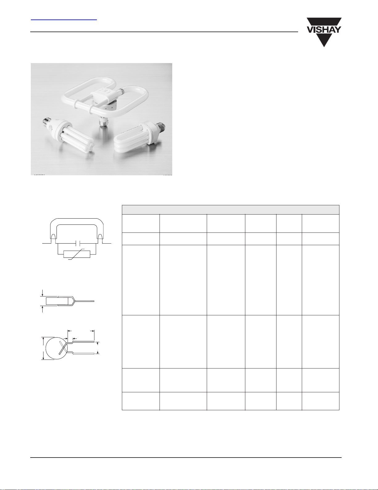
PTC Thermistors For Electronic Fluorescent Ballasts
FEATURES
• Electrode preheat thermistors for use in compact
fluorescent lamps (CFL) and electronic ballasts.
• Current limiting, time-delayed start-up extends lamp life.
• Quiet, flicker-free operation.
• Developed in cooperation with leading ballast designers.
• Both standard and custom parts are available.
• Economical, reliable and proven in millions of lamps
throughout the world.
APPLICATION CONSIDERATIONS
• Ignition time can be optimized to increase life of lamp.
• PTC resistance (R
resistance and application voltage, to control desired
electrode preheat current.
• Lamp preheat time is determined by time required for
thermistor to switch from low to high resistance state.
Preheat currents shown result in switch times of
approximately 1 second at 25°C. Lower currents result in
longer switch times.
) is chosen, along with filament
25
PTC THERMISTORS FOR ELECTRONIC FLUORESCENT BALLASTS
FLUORESCENT LAMP
C
PTC
Tinned Copper Clad Steel Wire
24 AWG when D ≤ 8.5mm
22 AWG when D ≥ 10mm
5mm
max
32mm min
4.5mm
max.
D
Options:
• High Temperature Coating
• Short Clipped Leads
• Other Wire Forms and Lead
Spacings
Note 1: R
Note 2: Instantaneous Voltage - Maximum rms voltage permitted across thermistor during fluorescent lamp start-up cycle.
Note 3: Continuous Voltage - Maximum rms voltage continuously applied across thermistor during normal lamp operation.
Note 4: Preheat Current - rms current (60Hz) which switches thermistor to high resistance in approximately 1 second at 25°C ambient.
Note 5: Size (mass) of PTC influences rate of I2R temperature increase. For given resistance, larger thermistors have longer switch times.
Note 6: P/N suffix (not shown) describes wire lead forms and other options.
- Nominal zero power resistance ± 25% at 25°C. For given diameter, higher resistance thermistors offer higher maximum voltages.
25
Optional coating slightly increases switch time.
LS = 5mm
RESISTANCE INSTANTANEOUS CONTINUOUS PREHEAT D
R
25
(OHMS) (V
150 265 80 215 4.5 307C1407
150 280 200 200 4.5 307C1414
50 175 50 430 5.5 307C1230
70 265 150 350 5.5 307C1654
100 260 95 370 5.5 307C1364
125 230 80 280 5.5 307C1259
150 235 90 260 5.5 307C1253
200 320 145 300 5.5 307C1223
240 350 150 260 5.5 307C1171
300 400 165 225 5.5 307C1225
380 410 170 205 5.5 307C1390
600 420 120 185 5.5 307C1252
600 460 200 170 5.5 307C1224
850 450 340 140 5.5 307C1622
100 340 265 390 7 307C1403
150 340 150 400 7 307C1306
180 350 165 380 7 307C1569
200 355 265 300 7 307C1375
300 370 75 270 7 307C1242
300 420 320 230 7 307C1360
500 480 400 190 7 307C1361
800 530 450 155 7 307C1362
850 520 175 190 7 307C1260
70 210 50 750 8.5 307C1367
70 300 140 725 8.5 307C1366
85 210 50 670 8.5 307C1363
150 400 100 550 8.5 307C1287
85 280 60 820 10 307C1258
100 310 90 750 10 307C1365
400 430 120 420 10 307C1422
VOLTAGE VOLTAGE CURRENT MAX. PART
123456
)(V
RMS
) (mA) (mm) NUMBER
RMS
www.vishay.com
10
ceramite.support@vishay.com
Document Number: 23088
Revision 14-May-02
 Loading...