

INPUT RECTIFIER DIODE
Bulletin I2158 05/00
SAFEIR Series
25ETS..S
V
< 1V @ 10A
F
Description/Features
The 25ETS.. rectifier SAFEIR series has been
optimized for very low forward voltage drop, with
moderate leakage. The glass passivation
technology used has reliable operation up to 150°C
junction temperature.
Typical applications are in input rectification and
these products are designed to be used with
International Rectifier Switches and Output
Rectifiers which are available in identical package
outlines.
Output Current in Typical Applications
Single-phase Bridge Three-phase Bridge Units
Capacitive input filter TA = 55°C, TJ = 125°C,
common heatsink of 1°C/W
Major Ratings and Characteristics
Characteristics 25ETS.. Units
I
FSM
V
RRM
20 23
Package Outline
= 300A
800 - 1200V
A
I
Sinusoidal
F(AV)
waveform
V
Range (*) 800 - 1200 V
RRM
I
FSM
VF@ 10 A, TJ = 25°C 1.0 V
T
J
(*) for higher voltage up to 1600V contact factory
25 A
300 A
- 40 to 150 °C
D2 Pak (SMD-220)
1
25ETS..S SAFEIR Series
Bulletin I2158 05/00
Voltage Ratings
V
, maximum V
RRM
Part Number
peak reverse voltage peak reverse voltage 150°C
VVmA
25ETS08S 800 900 1
25ETS12S 1200 1300
Provide terminal coating for voltages above 1200V
Absolute Maximum Ratings
Parameters 25ETS..S Units Conditions
I
Max. Average Forward Current 25 A @ TC = 106° C, 180° conduction half sine wave
F(AV)
I
Max. Peak One Cycle Non-Repetitive 250 10ms Sine pulse, rated V
FSM
Surge Current 300 10ms Sine pulse, no voltage reapplied
I2t Max. I2t for fusing 316 10ms Sine pulse, rated V
442 10ms Sine pulse, no voltage reapplied
2
I
√t Max. I2√t for fusing 4420 A2√s t = 0.1 to 10ms, no voltage reapplied
A
A2s
Electrical Specifications
, maximum non repetitive I
RSM
RRM
RRM
applied
applied
RRM
Parameters 25ETS..S Units Conditions
VFMMax. Forward Voltage Drop 1.14 V @ 25A, TJ = 25°C
r
Forward slope resistance 9.62 mΩ
t
V
Threshold voltage 0.87 V
F(TO)
IRMMax. Reverse Leakage Current 0.1 TJ = 25 °C
1.0 TJ = 150 °C
mA
TJ = 150°C
VR = rated V
Thermal-Mechanical Specifications
Parameters 25ETS..S Units Conditions
TJMax. Junction Temperature Range - 40 to 150 °C
T
Max. Storage Temperature Range - 40 to 150 °C
stg
R
Max. Thermal Resistance Junction 0.9 °C/W DC operation
thJC
to Case
R
Max. Thermal Resistance Junction 62 °C/W
thJA
to Ambient
R
Typ. Thermal Resistance Case 0.5 °C/W Mounting surface, smooth and greased
thCS
to Heatsink
wt Approximate Weight 2 (0.07) g (oz.)
T Mounting Torque Min. 6 (5)
Max. 12 (10)
Case Style D2Pak (SMD-220)
Kg-cm
(Ibf-in)
RRM
2
25ETS..S SAFEIR Series
Bulletin I2158 05/00
150
140
130
120
110
100
90
80
Maximu m Allowable Cas e Temperature (˚C)
0 5 10 15 20 25 30
Average Forward Current (A)
25ETS.. Series
R (DC) = 0.9 K/W
thJC
Conduction Angle
30˚
60˚
90˚
120˚
180˚
150
140
130
120
110
100
90
Max imu m A l l o wabl e Case Tem per atu re (˚C)
0 5 10 15 20 25 30 35 40
Average Forward Current (A)
25ETS.. Series
R (DC) = 0.9 K/W
thJC
30˚
60˚
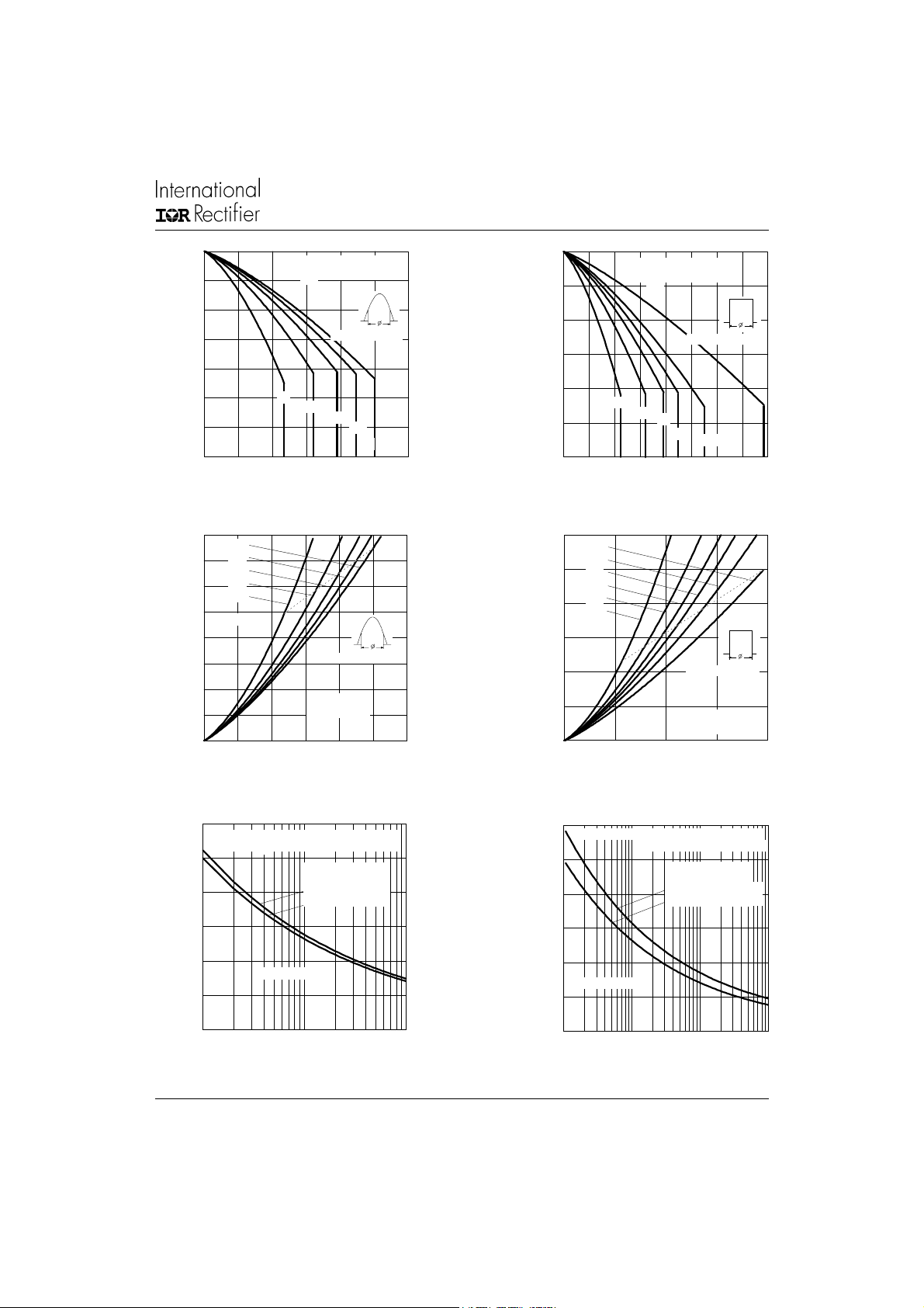
Fig. 1 - Current Rating Characteristics Fig. 2 - Current Rating Characteristics
40
180˚
120˚
35
90˚
60˚
30
30˚
25
RMS Limit
20
15
10
5
0
Maximu m A verage F orward Power Loss (W)
0 5 10 15 20 25 30
Average Forward Current (A)
Conduction Angle
25ETS.. Series
T = 150˚C
J
Fig. 3 - Forward Power Loss Characteristics
60
DC
180˚
50
120˚
90˚
60˚
40
30˚
30
RMS Limit
20
10
0
Maximu m Av erage F orward Power Loss (W)
010203040
Average Forward Current (A)
Fig. 4 - Forward Power Loss Characteristics
Conduction Period
90˚
120˚
Conduction Period
25ETS.. Series
T = 150˚C
J
180˚
DC
300
At Any Rated Load Condition And With
Rated V Applied Following Surge.
RRM
Initial T = 150˚C
J
200
100
0
Maximu m A verage F orward Power Loss (W)
1 10 100
Average Forward Current (A)
@ 60 Hz 0.0083 s
@ 50 Hz 0.0100 s
25ETS.. Series
Fig. 5 - Maximum Non-Repetitive Surge Current
300
Maximum Non Repetitive Surge Current
200
100
25ETS.. Series
0
Maximu m Allowable Cas e Temperature (˚C)
0.01 0.1 1 10
Versus Pulse Train Duration .
Initial T = 150˚C
J
No Voltage Reapplied
Rated V Reapplied
RRM
Average Forward Current (A)
J
Fig. 6 - Maximum Non-Repetitive Surge Current
3

25ETS..S SAFEIR Series
Bulletin I2158 05/00
1000
100
10
T = 25˚C
J
T = 150˚C
J
In stan t aneous Forw ard Current ( A)
1
012345
Instantaneous Forward Voltage (V)
25ETS.. Series
Fig. 7 - Forward Voltage Drop Characteristics
1
D = 0.50
thJC
D = 0.33
D = 0.25
D = 0.17
D = 0.08
0.1
Transient Thermal Impedance Z (˚C/W)
0.01
0.0001 0.001 0.01 0.1 1 10 100
Single Pulse
Square Wave Pulse Duration (s)
Fig. 8 - Thermal Impedance Z
Steady State Value
(DC Operation)
Characteristics
thJC
25ETS. .Series
4

Ordering Information Table
25ETS..S SAFEIR Series
Bulletin I2158 05/00
Device Code
25 E T S 12 S TRL
1
1 - Current Rating
2 - Circuit Configuration: E = Single Diode
3 - Package: T = TO-220AC
4 - Type of Silicon: S = Standard Recovery Rectifier
5 - Voltage code: Code x 100 = V
6 - S = TO-220 D2Pak (SMD-220) Version
7 - Tape and Reel Option
TRL = Left Reel
TRR = Right Orientation Reel
(*) for higher voltage up to 1600V contact factory
3
Outline Table
10.16 (0.40)
REF.
1.40 (0.055)
3X
1.14 (0.045)
93°
2.61 (0.10)
2.32 (0.09)
8.89 (0.35)
REF.
0.93 (0.37)
2X
0.69 (0.27)
15.49 (0.61)
14.73 (0.58)
524
RRM
6.47 (0.25)
6.18 (0.24)
6 7
08 = 800V
12 = 1200V
4.69 (0.18)
4.20 (0.16)
1.32 (0.05)
1.22 (0.05)
5.28 (0.21)
4.78 (0.19)
0.55 (0.02)
0.46 (0.02)
MINIMUM RECOMMENDED FOOTPRINT
11.43 (0.45)
13
2
4.57 (0.18)
4.32 (0.17)
0.61 (0.02) MAX.
5.08 (0.20) REF.
Dimensions in millimeters and inches
8.89 (0.35)
3.81 (0.15)
2.08 (0.08)
2X
17.78 (0.70)
2.54 (0.10)
2X
5

25ETS..S SAFEIR Series
Bulletin I2158 05/00
Marking Information
EXAMPLE: THIS IS AN 25ETS12S
BASE
+
2
(K)
(A)
1
(A)
3
--
Tape & Reel Information
TRR
FEED DIRECTION
TRL
1.8 5 (0.0 73 )
1.6 5 (0.0 65 )
4.10 (0. 161)
3.90 (0. 153)
10 .90 (0 .42 9)
10 .70 (0 .42 1)
INTERNATIONAL
RECTIFIER LOGO
ASSEMBLY
LOT CODE
1.60 (0.063)
1.50 (0.059)
1.60 (0.063)
1.50 (0.059)
11 .60 (0.45 7)
11 .40 (0.44 9)
1.75 (0.069)
1.25 (0.049)
16 .10 (0.6 34)
15 .90 (0.6 26)
(K)
25ETS12S
9G3A
(A)
DIA.
DIA.
9512
(A)
15.42 (0.609)
15.22 (0.601)
PART NUMBER
DATE CODE (YYWW)
YY = YEAR
WW = WEEK
0.368 (0.0145)
0.342 (0.0135)
24 .30 (0.957 )
23 .90 (0.941 )
4.7 2 (0 .186 )
4.5 2 (0 .178 )
FEED DIRECTION
360 (14.173)
DIA. MAX.
6
13.50 ( 0.532)
12.80 ( 0.504)
DIA.
Dimensions in millimeters and inches
26 .40 (1 .03 9)
24 .40 (0 .96 1)
60 (2.3 62)
DIA. MIN.
SMD-2 20 Tape & R eel
When order ing, ind icate the part
number, part orientation, and the
quantity. Quantities are in multiples
of 8 00 pieces pe r reel for bo th
TRL a nd TRR .

25ETS..S SAFEIR Series
Bulletin I2158 05/00
WORLD HEADQUARTERS: 233 Kansas St., El Segundo, California 90245 U.S.A. Tel: (310) 322 3331. Fax: (310) 322 3332.
EUROPEAN HEADQUARTERS: Hurst Green, Oxted, Surrey RH8 9BB, U.K. Tel: ++ 44 1883 732020. Fax: ++ 44 1883 733408.
IR SOUTHEAST ASIA: 1 Kim Seng Promenade, Great World City West Tower,13-11, Singapore 237994. Tel: ++ 65 838 4630.
http://www.irf.com Fax-On-Demand: +44 1883 733420 Data and specifications subject to change without notice.
IR CANADA: 15 Lincoln Court, Brampton, Markham, Ontario L6T3Z2. Tel: (905) 453 2200. Fax: (905) 475 8801.
IR GERMANY: Saalburgstrasse 157, 61350 Bad Homburg. Tel: ++ 49 6172 96590. Fax: ++ 49 6172 965933.
IR ITALY: Via Liguria 49, 10071 Borgaro, Torino. Tel: ++ 39 11 4510111. Fax: ++ 39 11 4510220.
IR FAR EAST: K&H Bldg., 2F, 30-4 Nishi-Ikebukuro 3-Chome, Toshima-Ku, Tokyo, Japan 171. Tel: 81 3 3983 0086.
IR TAIWAN: 16 Fl. Suite D.207, Sec. 2, Tun Haw South Road, Taipei, 10673, Taiwan. Tel: 886 2 2377 9936.
7
 Loading...