

.
查询2322-592-1316供应商
2322 59. .....
Vishay BCcomponents
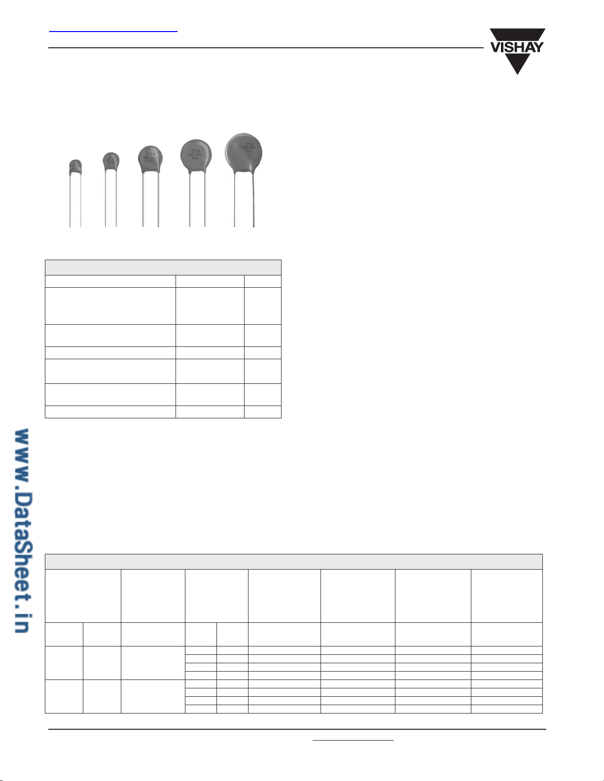
Varistors
FEATURES
• Zinc oxide disc, epoxy coated
Straight leads
•
Straight leads with flange (2322 592 and 593 series only)
•
•
Kinked leads.
APPLICATION
•
Suppression of transients.
DESCRIPTION
QUICK REFERENCE DATA
PARAMETER VALUE UNIT
Maximum continuous voltage:
RMS 14 to 680 V
DC 18 to 895 V
Maximum non-repetitive transient
current I
Robustness of terminations 10 N
Drop test:
Height of fall 1 m
Detailed specification based on
Climatic category 40/085/56
(8 × 20 µs)
nrp
100 to 6500 A
CECC 42000
ORDERING INFORMATION
The varistors are available in a number of packaging options:
•
Bulk
• On tape on reel
•
On tape in ammopack.
The basic ordering code for each option is given in tables
titled Varistors on Tape on Reel, Varistors on Tape in
Ammopack and Varistors in Bulk. To complete the catalog
number and to determine the required operating parameters,
see Electrical Data and Ordering Information table.
The varistors consist of a disc of lowtwo tinned solid copper leads. They are coated with a layer of
ochre coloured epoxy, which provides electrical, mechanical
and climatic protection. The encapsulation is resistant to all
cleaning solvents in accordance with “IEC 60068-2-45” .
MOUNTING
The varistors are suitable for processing on automatic
insertion and cutting and bending equipment.
Varistors with flanged leads provide better positioning on
printed-circuit boards (PCB) and more accurate control over
component height. This is important for hand mounting and
automatic insertion techniques; see Outlines of flanged leads
drawing.
Soldering
≤ 240 ° C
; duration
≤
5 s
Resistance to heat
≤ 260 ° C; duration ≤ 5 s.
MARKING
The varistors are marked with the following information:
• Maximum continuous RMS voltage
• Series number (592, 593, 594, 595 or 596)
•
Manufacturers logo
• Date of manufacture.
INFLAMMABILITY
The varistors are non-flammable.
ceramic material with
β
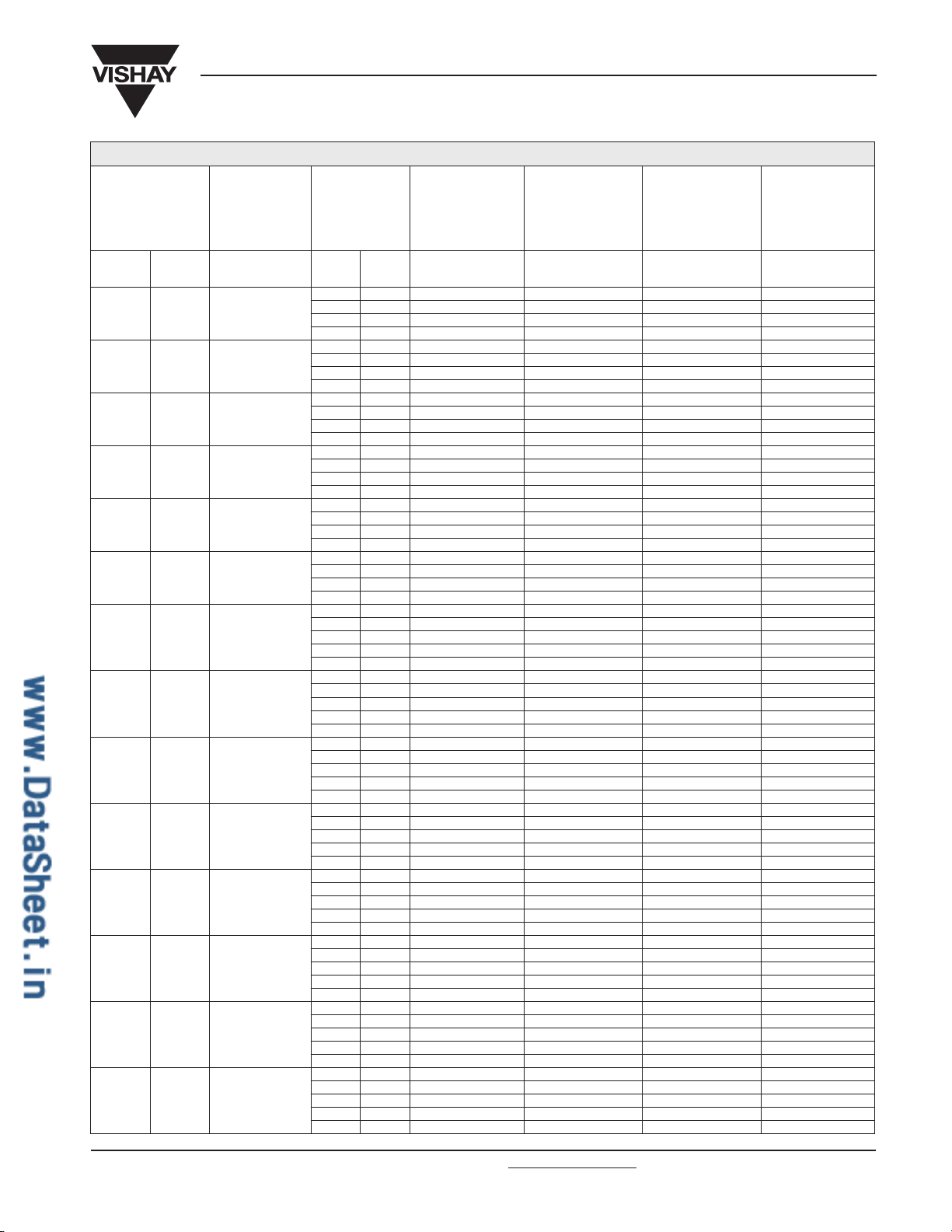
ELECTRICAL DATA AND ORDERING INFORMATION
MAXIMUM
CONTINUOUS
VOLTAGE
(2)
RMS
(V)
14 18 22 48 1.0 0.5 100 1300 592 .1406
17 22 27 60 1.0 0.7 100 1050 592 .1706
www.vishay.com For technical questions contact: nlr
216 Revision: 10-Oct-03
DC
(V)
VO LTAGE
(3)
1 mA
(V)
MAXIMUM
VO LTAG E at
at
STATED
CURRENT
V
(V)
43 2.5 1.7 250 2800 593 .1406
43 5.0 4.3 500 6000 594 .1406
43 10.0 5.4 1000 15000 595 .1406
53 2.5 2.0 250 2000 593 .1706
53 5.0 5.3 500 4000 594 .1706
53 10.0 6.9 1000 10000 595 .1706
I
(A)
MAXIMUM
ENERGY
(10
(4)
××
××
1000 µs)
(J) (A) (PF) 2322 ... .....
MAXIMUM
NON-REP.
TRANSIENT
CURRENT
I
nrp
.europe@vishay.com Document Number: 29081
(8 ××
××
20 µs)
(5)
TYPICAL
CAPACITANCE at
1 kHZ
CATALOG
NUMBERS(1)
(6)
(6)
(6)
(6)
(6)
(6)
(6)
(6)
2322 59. .....
Varistors
Vishay BCcomponents
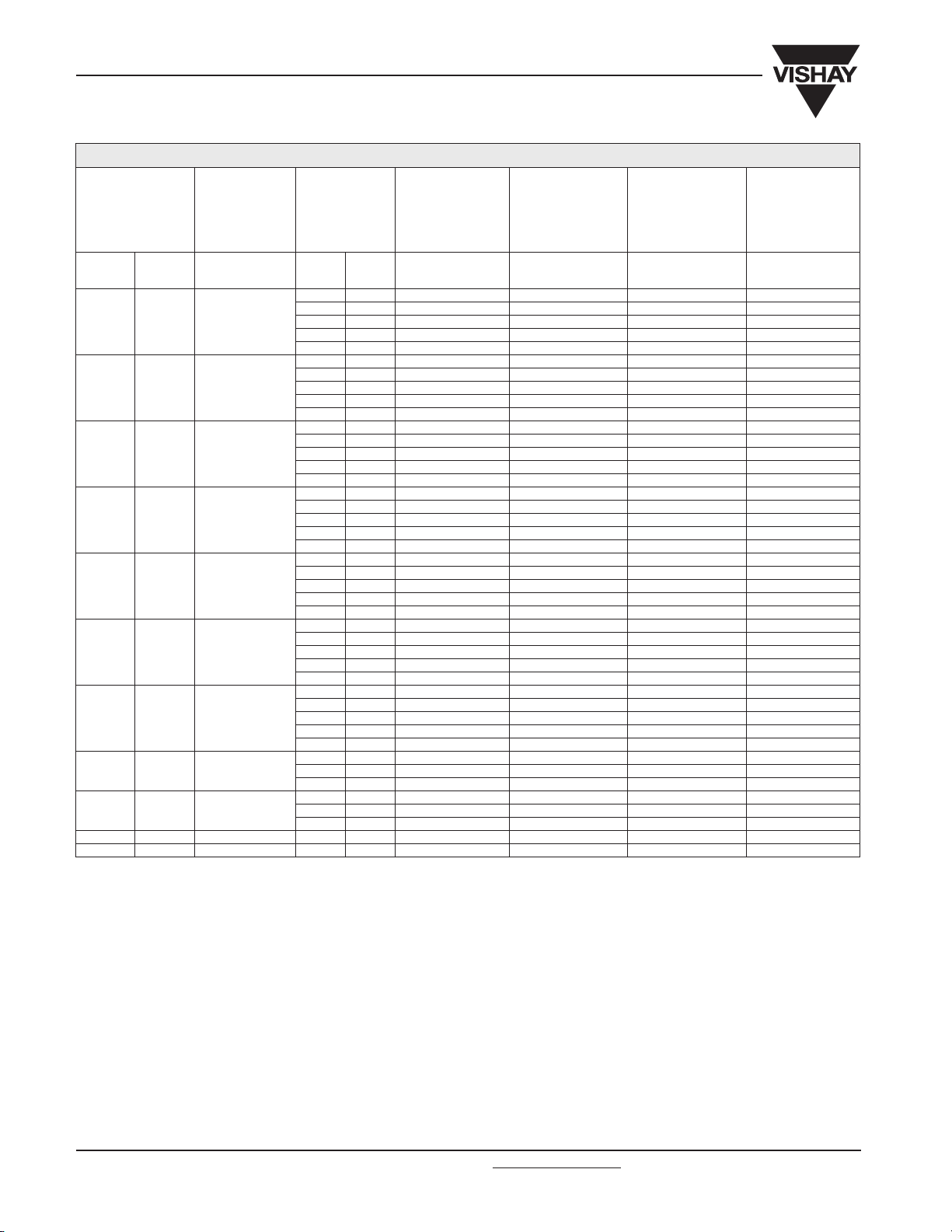
ELECTRICAL DATA AND ORDERING INFORMATION
MAXIMUM
NON-REP.
TRANSIENT
CURRENT
××
20 µs)
I
(8
××
nrp
(5)
TYPICAL
CAPACITANCE at
1 kHZ
CATALOG
NUMBERS(1)
(6)
(6)
(6)
(6)
(6)
(6)
(6)
(6)
.europe@vishay.com www.vishay.com
MAXIMUM
CONTINUOUS
VOLTAGE
(2)
RMS
(V)
DC
(V)
VO LTAGE
1 mA
(V)
(3)
at
VO LTAG E at
STATED
CURRENT
MAXIMUM
V
(V)
I
(A)
MAXIMUM
××
××
1000 µs)
(4)
ENERGY
(10
(J) (A) (PF) 2322 ... .....
20 26 33 73 1.0 0.8 100 900 592 .2006
65 2.5 2.5 250 1500 593 .2006
65 5.0 6.5 500 3000 594 .2006
65 10.0 8.8 1000 7500 595 .2006
25 31 39 86 1.0 0.9 100 500 592 .2506
77 2.5 3.0 250 1350 593 .2506
77 5.0 7.7 500 2600 594 .2506
77 10.0 9.4 1000 6500 595 .2506
30 38 47 96 1.0 1.1 100 700 592 .3006(6)
93 2.5 3.6 250 1600 593 .3006(6)
93 5.0 9.2 500 2700 594 .3006(6)
90 10.0 12.0 1 000 6 000 595 .3006(6)
35 45 56 123 1.0 1.4 100 560 592 .3506(6)
115 2.5 4.4 250 1300 593 .3506(6)
110 5.0 11.0 500 2200 594 .3506(6)
105 10.0 14.0 1 000 4 800 595 .3506(6)
40 56 68 145 1.0 1.6 100 460 592 .4006(6)
135 2.5 5.2 250 1000 593 .4006(6)
130 5.0 13.0 500 1800 594 .4006(6)
130 10.0 17.0 1 000 3 800 595 .4006(6)
50 65 82 145 5.0 2.6 400 370 592 .5006(6)
140 10.0 7.0 1200 900 593 .5006(6)
140 25.0 12.0 2 500 1 500 594 .5006(6)
140 50.0 21.0 4 500 3 100 595 .5006(6)
60 85 100 165 5.0 2.9 400 290 592 .6006(6)
165 10.0 8.3 1200 700 593 .6006(6)
165 25.0 15.0 2 500 1 200 594 .6006(6)
165 50.0 24.0 4 500 2 300 595 .6006(6)
165 100.0 56.0 6500 4700 596 .6006
75 100 120 190 5.0 3.4 400 240 592 .7506(6)
200 10.0 10.0 1 200 530 593 .7506(6)
200 25.0 18.0 2 500 1 000 594 .7506(6)
200 50.0 29.0 4 500 1 900 595 .7506(6)
200 100.0 64.0 6 500 3900 596 .7506
95 125 150 230 5.0 4.1 400 180 592 .9506(6)
250 10.0 13.0 1 200 450 593 .9506(6)
250 25.0 22.0 2 500 800 594 .9506(6)
250 50.0 37.0 4 500 1 500 595 .9506(6)
250 100.0 88.0 6 500 3000 596 .9506
130 170 205 310 5.0 5.5 400 130 592 .1316(6)
340 10.0 17.0 1 200 320 593 .1316(6)
340 25.0 30.0 2 500 580 594 .1316(6)
340 50.0 56.0 4 500 1 050 595 .1316(6)
200 340 100.0 114.0 6500 2100 596 .1316
140 180 220 350 5.0 6.3 400 120 592 .1416(6)
370 10.0 21.0 1 200 290 593 .1416(6)
370 25.0 33.0 2 500 540 594 .1416(6)
370 50.0 57.0 4 500 950 595 .1416(6)
360 100.0 124.0 6500 1900 596 .1416
150 200 240 395 5.0 7.1 400 110 592 .1516(6)
400 10.0 20.0 1 200 270 593 .1516(6)
400 25.0 36.0 2 500 490 594 .1516(6)
400 50.0 59.0 4 500 850 595 .1516(6)
395 100.0 134.0 6500 1700 596 .1516
175 225 275 410 5.0 7.3 400 90 592 .1716(6)
455 10.0 23.0 1 200 230 593 .1716(6)
455 25.0 41.0 2 500 430 594 .1716(6)
455 50.0 67.0 4 500 750 595 .1716(6)
270 455 100.0 158.0 6500 1500 596 .1716
230 300 360 560 5.0 10.0 400 70 592 .2316(6)
600 10.0 30.0 1 200 170 593 .2316(6)
600 25.0 54.0 2 500 320 594 .2316(6)
600 50.0 88.0 4 500 540 595 .2316(6)
595 100.0 208.0 6500 1100 596 .2316
Document Number: 29081 For technical questions contact: nlr
Revision: 10-Oct-03 217
2322 59. .....
Vishay BCcomponents
Varistors
ELECTRICAL DATA AND ORDERING INFORMATION
MAXIMUM
NON-REP.
TRANSIENT
CURRENT
××
××
I
(8
20 µs)
nrp
(5)
TYPICAL
CAPACITANCE at
1 kHZ
CATALOG
NUMBERS(1)
× 1000 µs is given as a reference for longer
(virtual time of half I
2
value, following “IEC 60060-2,
p
.europe@vishay.com Document Number: 29081
MAXIMUM
CONTINUOUS
VOLTAGE
(2)
RMS
(V)
DC
(V)
VO LTAGE
1 mA
(V)
(3)
at
VO LTAG E at
STATED
CURRENT
MAXIMUM
V
(V)
I
(A)
MAXIMUM
××
1000 µs)
××
(4)
ENERGY
(10
(J) (A) (PF) 2322 ... .....
250 320 390 600 5.0 11.0 400 60 592 .2516(6)
650 10.0 33.0 1 200 160 593 .2516(6)
650 25.0 58.0 2 500 300 594 .2516(6)
650 50.0 96.0 4 500 480 595 .2516(6)
650 100.0 240.0 6500 960 596 .2516
275 350 430 695 5.0 12.0 400 55 592 .2716(6)
710 10.0 36.0 1 200 140 593 .2716(6)
710 25.0 63.0 2 500 270 594 .2716(6)
710 50.0 104.0 4500 440 595 .2716(6)
710 100.0 264.0 6500 900 596 .2716
300 385 470 750 5.0 13.0 400 50 592 .3016(6)
800 10.0 40.0 1 200 130 593 .3016(6)
800 25.0 71.0 2 500 240 594 .3016(6)
800 50.0 117.0 4500 400 595 .3016(6)
775 100.0 280.0 6500 810 596 .3016
320 420 510 800 5.0 15.0 400 45 592 .3216(6)
850 10.0 44.0 1 200 120 593 .3216(6)
850 25.0 77.0 2 500 220 594 .3216(6)
850 50.0 120.0 4500 370 595 .3216(6)
842 100.0 296.0 6500 750 596 .3216
385 505 620 1000 5.0 18.0 400 40 592 .3816(6)
1025 10.0 51.0 1200 95 593 .3816(6)
1025 25.0 67.0 2500 180 594 .3816(6)
1025 50.0 110.0 4500 280 595 .3816(6)
1025 100.0 328.0 6500 570 596 .3816
420 560 680 1100 5.0 20.0 400 35 592 .4216(6)
1120 10.0 56.0 1200 85 593 .4216(6)
1120 25.0 73.0 2500 165 594 .4216(6)
1120 50.0 120.0 4500 250 595 .4216(6)
1120 100.0 344.0 6500 510 596 .4216
460 615 750 1200 5.0 21.0 400 30 592 .4616(6)
1240 10.0 63.0 1200 75 593 .4616(6)
1240 25.0 82.0 2500 150 594 .4616(6)
1240 50.0 135.0 4500 225 595 .4616(6)
1240 100.0 360.0 6500 460 596 .4616
510 670 820 1355 25.0 89.0 2500 135 594 .5116(6)
1355 50.0 145.0 4500 220 595 .5116(6)
1355 100.0 376.0 6500 450 596 .5116
550 745 910 1500 25.0 98.0 2500 120 594 .5516(6)
1500 50.0 160.0 4500 180 595 .5516(6)
1500 100.0 408.0 6500 370 596 .5516
625 825 1000 1650 100.0 448.0 6 500 320 596 .6216
680 895 1100 1815 100.0 496.0 6 500 270 596 .6816
Notes
1. Lists with products certified according to UL (E98144), VDE (122380E), CSA (219883) and CECC (42201-001) are available at
www.vishay.com or on request.
2. The sinusoidal voltage is assumed as the normal operating condition. If a non-sinusoidal voltage is present, type selection should be based
on multiplying the peak voltage by a factor of 0.707.
3. The voltage measured at 1 mA meets the requirements of “paragraph 4.3 of CECC specification 42000” .
The tolerance on the voltage at 1 mA is
± 10%.
4. High energy surges are generally of longer duration. The maximum energy for one pulse of 10
duration pulses. This pulse can be characterised by peak current (I
section 6” ). If V
EKV
× Ip× t2×=
where:
a) K is dependent on the value of t
5. A current wave of 8
is the clamping voltage corresponding to I
p
p
when the value of t
2
× 20 µs (requirement of “paragraph B.2.10.1 of CECC specification 42000” ) is used as a standard for pulse current and
is between 8 µs and 10 µs; see Peak Current as a Function of Pulse Width drawing.
1
) and pulse width t
p
, the energy absorbed in the varistor is determined by the formula:
p
clamping voltage ratings. The maximum non-repetitive transient current is given for one pulse applied during the life of the component.
6. Replace the last digit of the catalog number with a ‘7’ for ordering on tape in ammopack.
www.vishay.com For technical questions contact: nlr
218 Revision: 10-Oct-03
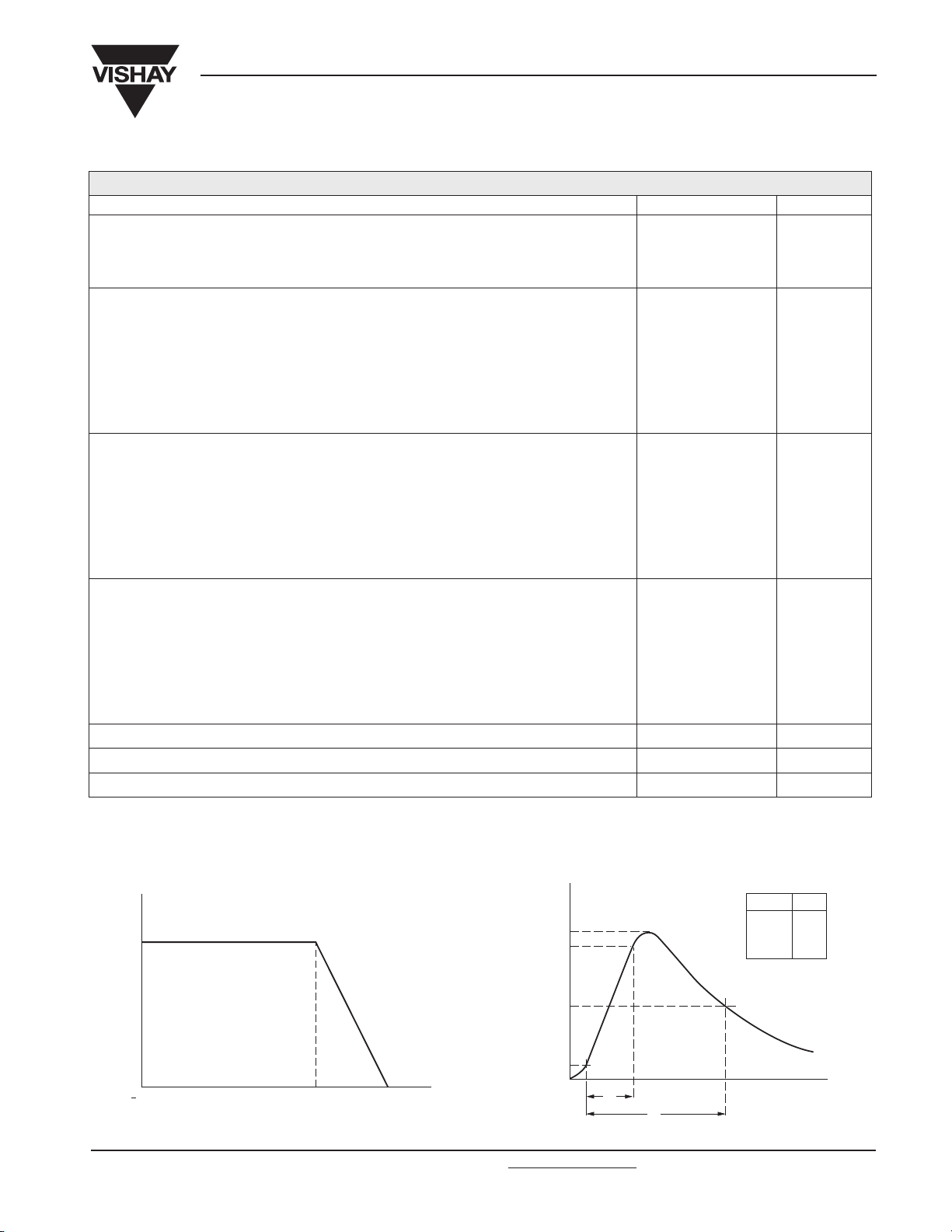
I
p
t
1
t
2
t
(µs)
(%)
100
50
90
10
0
t
2
(µs)
20
50
100
1000
1
1.2
1.3
1.4
K
2322 59. .....
Varistors
Vishay BCcomponents
ELECTRICAL CHARACTERISTICS
ELECTRICAL DATA
PARAMETER VALUE UNIT
Maximum continuous voltage:
RMS 14 to 680 V
DC 18 to 895 V
× 20 µs:
Maximum non-repetitive transient current (I
2322 592 ..... 100 or 400 A
2322 593 ..... 250 or 1200 A
2322 594 ..... 500 or 2500 A
2322 595 ..... 1000 or 4500 A
2322 596 ..... 6500 A
Thermal resistance:
2322 592 .....
2322 593 .....
2322 594 .....
2322 595 .....
2322 596 .....
Maximum dissipation:
2322 592 ..... 100 mW
2322 593 ..... 250 mW
2322 594 ..... 400 mW
2322 595 ..... 600 mW
2322 596 ..... 1000 mW
Temperature coefficient of voltage at 1 mA maximum
Voltage proof between interconnected leads and case 2500 V
Climatic category 40/085/56
nrp
) (8
≈ 80 K/W
≈ 70 K/W
≈ 60 K/W
≈ 50 K/W
≈ 40 K/W
− 0.065 %/K
DERATING CURVE PEAK CURRENT AS A FUNCTION OF
PULSE WIDTH
V
(%)
100
0
40 80
Document Number: 29081 For technical questions contact: nlr
Revision: 10-Oct-03 219
125
o
T ( C)
.europe@vishay.com www.vishay.com
2322 59. .....
Vishay BCcomponents
VARISTORS IN BULK
2322 592 .....
TYPE
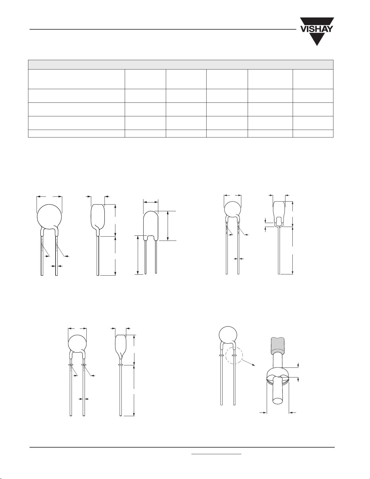
Straight leads; see Outline of components
with straight leads drawing(1)
Straight leads with flange; see Outline of
components with flanged leads drawing
Kinked leads; see Outline of components
with kinked leads drawing
Package quantities
Note
1. Outline of the Ø20 mm differs from the other dimensions.
DIMENSIONS in millimeters
Outline of component with straight leads.
D T
∅∅
∅∅
5 mm
14 V to 460 V
5...6 5...6 5...6 5...6 5...6
7...6 7...6
6...6 6...6 6...6 6...6 6...6
250 250 250 100 and 250 1 000
T
Varistors
2322 593 .....
∅∅
∅∅
7 mm
14 V to 460 V
2322 594 .....
∅∅
∅∅
10 mm
14 V to 550 V
−−−
Outline of component with kinked leads.
2322 595 .....
∅∅
∅∅
14 mm
14 V to 550 V
TD
2322 596 .....
∅∅
∅∅
20 mm
60 V to 680 V
F
∅d
For dimensions, see Component
Dimensions and catalog Numbers table.
Outline of component with flanged leads.
D T
F
A
0
A
L
L
Ø20 mm only.
A
0
A
For dimensions, see Component
Dimensions and catalog Numbers table.
Outline of flanged leads.
1 min.
F
L
∅d
0.3
L
∅d
1.4 to 1.6
For dimensions, see Component
Dimensions and catalog Numbers table.
www.vishay.com For technical questions contact: nlr
220 Revision: 10-Oct-03
.europe@vishay.com Document Number: 29081

2322 59. .....
Varistors
COMPONENT DIMENSIONS AND CATALOG NUMBERS in millimeters
D
MAX.
7.0 9.0 11.0 27.0 6 4.1 0.6
9.0 11.0 13.0 27.0 6 4.1 0.6
13.5 15.5 18.0 17.0 7 4.4 0.8
17.0 19.0 23.0 16.0 7 4.4 0.8
23.0 25.0 28.0 24.0 7 5.0 1.0
VARISTORS ON TAPE ON REEL
TYPE
A
MAX.
A
0
MAX.
L
MIN.
T
MAX.
T
MIN.
∅∅∅∅DF
±±±±0.05 5 +0.6/−−−−0.1 2322 592 .....
±±±±0.05 5 +0.6/−−−−0.1 2322 593 .....
±±±±0.05 7.5 ±±±±0.8 2322 594 .....
±±±±0.05 7.5 ±±±±0.8 2322 595 .....
±±±±0.05 10 ±±±±0.8 2322 596 .....
2322 592 .....
∅∅∅∅5 mm
14 V to 460 V
2322 593 .....
∅∅∅∅7 mm
14V to 460 V
Vishay BCcomponents
CATALOG NUMBER
2322 594 .....
∅∅∅∅10 mm
14 V to 550 V
2322 595 .....
∅∅∅∅14 mm
14V to 460 V
Straight leads:
H = 18 mm (2322 594 and 2322 595); see Taped version with
straight leads (only for 2322 594 and 2322 595 series) drawing
H = 20 mm (2322 592 and 2322 593); see Taped version with
straight leads (only for 2322 592 and 2322 593 series) drawing
Straight leads with flange; H
flanged leads (only for 2322 592 and 2322 593 series) drawing
Straight leads with flange; H0 = 18.25 mm; see Taped version with
flanged leads (only for 2322 592 and 2322 593 series) drawing
Kinked leads; H
leads (only for 2322 594 and 2322 595 series) drawing
Kinked leads; H
(only for 2322 592 and 2322 593 series) drawing
Package quantities
14 V to 385 V 3000 3 000 1 500 1 500
≥≥≥≥420 V −−
= 18.25 mm; see Taped version with kinked
0
= 16 mm; see Taped version with kinked leads
0
= 16 mm; see Taped version with
0
– – 0...6 0...6
0...6 0...6 – –
1...6 1...6 −−
2...6 2...6 −−
3...6 3...6 3...6 3...6
8...6 8...6 8...6 8...6
−−
−−
−−
−−
−−
1000
−−
510 V to 550 V
Document Number: 29081 For technical questions contact: nlr
Revision: 10-Oct-03 221
−−
.europe@vishay.com www.vishay.com
−−
−−
1200 1 200

2322 59. .....
Vishay BCcomponents
Varistors
PACKAGING
TAPED VERSION WITH STRAIGHT LEADS (only for 2322 592 and 2322 593 series).
P
∆
D
F
d
D
0
P
0
p
1
∆ p
W
2
W
1
W
W
0
FP
detail A
T
∆
h
H
A
∆
h
A
t
h
T
h
A
TAPED VERSION WITH STRAIGHT LEADS (only for 2322 594 and 2322 595 series).
P
∆
D
F
d
P
0
p
1
∆ p
W
2
W
1
W
W
0
FP
D
0
detail A
T
∆
h
H
A
∆
h
A
t
h
T
h
A
www.vishay.com For technical questions contact: nlr
.europe@vishay.com Document Number: 29081
222 Revision: 10-Oct-03

2322 59. .....
42 1
56 max
22.5
1
0
30
77 85.6 92
356
max
18
3
46 1
60 max
22.5
1
0
30
77 85.6 92
356
max
18
3
TAPED VERSION WITH KINKED LEADS
(only for 2322 592 and 2322 593 series).
P
F
0
∆p ∆p
W
W
1
W
D
0
D
∅d
P
1
P
2
0
detail A
∆h ∆h
1 min.
W
A
Varistors
T
A
0
H
0
t
Vishay BCcomponents
TAPED VERSION WITH KINKED LEADS
(only for 2322 594 and 2322 595 series).
P
∆p ∆p
D
∅d
W
2
W
1
W
0
P
F
1
P
0
D
0
detail A
∆h ∆h
1 min.
W
A
T
A
0
H
0
t
For dimensions, see Taping data table.
TAPED VERSION WITH FLANGED LEADS
(only for 2322 592 and 2322 593 series).
P
∆ p ∆ p
D
d
H
W
0
2
W
P
F
1
P
0
D
0
1
W
W
0
detail A
T
∆ h ∆ h
A
t
For dimensions, see Taping data table.
DIMENSIONS OF REELS in millimeters
A
0
For dimensions, see Taping data table.
Document Number: 29081 For technical questions contact: nlr
Revision: 10-Oct-03 223
.europe@vishay.com www.vishay.com

2322 59. .....
Vishay BCcomponents
Varistors
TAPING DATA (based on “IEC 60286-2” )
SYMBOL PARAMETER
D body diameter see Component Dimensions table
T total thickness see Component Dimensions table
; A mounting height see Component Dimensions table
A
0
∅d lead diameter see Component Dimensions table
F lead to lead distance see Component Dimensions table guaranteed between component and tape
P component pitch 12.7 or 25.4 ±1.0
P
0
P
1
∆p component alignment 0.0 ±1.3
∆h component alignment 0.0 ±2.0
W tape width 18.0 +1.0/−0.5
W
0
W
1
W
2
H height between component
H
0
D
0
t total tape thickness ≤1.4 with cardboard tape 0.5 ±0.1 mm
feed hole pitch 12.7 ±0.3 cumulative pitch error ±1
feed hole centre to lead centre 3.85 or 8.95 ±0.7 guaranteed between component and tape
hold down tape width ≥12.5
hole position 9.0 ±0.5
hold down tape position ≤3.0
and tape centre
lead-wire flange height 16.0 or 18.25 ±0.5 flanged and kinked lead versions
feed hole diameter 4.0 ±0.2
DIMENSIONS
NOMINAL (mm)
18.0 +2.0/−0.0 straight lead version 2322 594 and 2322 595
20.0 +2.0/−0.0 straight lead version 2322 592 and 2322 593
TOLERANCE
(mm)
REMARKS
VARISTORS ON TAPE IN AMMOPACK
2322 592 .....
TYPE
Straight leads;
H = 18 or 20 mm; see Taped version
with straight leads (only for 2322 592
and 2322 593 series) and Taped
version with straight leads (only for
2322 594 and 2322 595 series)
drawings
Straight leads with flange;
H0 = 16 mm; see Taped version with
flanged leads (onlt for 2322 592 and
2322 593 series) drawing
Straight leads with flange;
H0 = 18.25 mm; see Taped version
with flanged leads (onlt for 2322 592
and 2322 593 series) drawing
Kinked leads;
= 18.25 mm; see Taped version
H
0
with kinked leads (only for 2322 594
and 2322 595 series) drawing
Kinked leads;
H0 = 16 mm; see Taped version with
kinked leads (only for 2322 592 and
2322 593 series) drawing
Package quantities
14 to 175 V 1500 1500 750 750
230 to 460 V 1000 1000 −−
230 to 300 V −−600 600
320 to 550 V −−500 500
∅∅∅∅MM
14 V TO 460 V
0...7 0...7 0...7 0...7
1...7 1...7 −−
2...7 2...7 −−
3...7 3...7 3...7 3...7
8...7 8...7 8...7 8...7
2322 593 .....
∅∅∅∅7 MM
14 V TO 460 V
2322 594 .....
∅∅∅∅10 MM
14 V TO 550 V
2322 595 .....
∅∅∅∅14 MM
14V TO 550 V
www.vishay.com For technical questions contact: nlr
224 Revision: 10-Oct-03
.europe@vishay.com Document Number: 29081

2322 59. .....
Varistors
DIMENSIONS OF AMMOPACK in millimeters
340 max
250
max
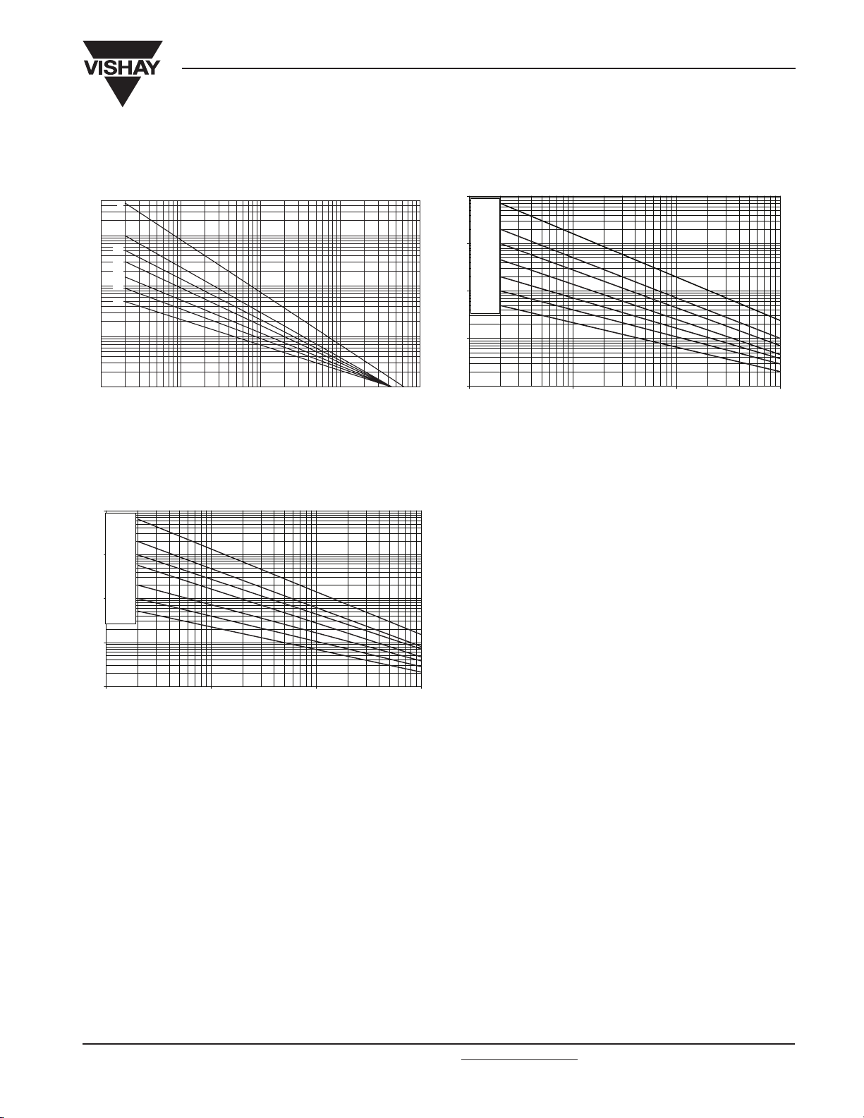
V/I CHARACTERISTICS, 14 V TO 40 V (RMS);
2322 592 series.
V
(V)
400
300
200
100
80
60
50
40
30
20
10
5
10
max. leakage current
4
10
3
10
10
2
max. clamping voltage
1
10
.4006
.3506
.3006
.2506
.2006
.1706
.1406
11010210
I (A)
Vishay BCcomponents
52 or 55 max
V/I CHARACTERISTICS, 50V TO 460 V (RMS);
2322 592 series.
max. leakage current max. clamping voltage
3000
V
(V)
2000
1000
800
600
500
400
300
200
100
80
60
50
40
5
10
10
3
3
4
10
10
1
2
110
2
10
10
.4616
.4216
.3816
.3216
.3016
.2716
.2516
.2316
.1716
.1516
.1416
.1316
.9506
.7506
.6006
.5006
4
3
10
10
I (A)
V/I CHARACTERISTICS, 14V TO 40 V (RMS);
2322 593 series.
V
(V)
400
300
200
100
80
60
50
40
30
20
10
10
max. leakage current
5
10
4
3
10
10
2
max. clamping voltage
1
10
11010210
I (A)
V/I CHARACTERISTICS, 50V TO 460 V (RMS);
2322 593 series.
max. leakage current max. clamping voltage
3000
.4006
.3506
.3006
.2506
.2006
.1706
.1406
V
(V)
2000
1000
800
600
500
400
300
200
100
80
60
50
40
3
5
10
10
3
4
10
10
1
2
10 I (A)110
.4616
.4216
.3816
.3216
.3016
.2716
.2516
.2316
.1716
.1516
.1416
.1316
.9506
.7506
.6006
.5006
3
2
10
10
Document Number: 29081 For technical questions contact: nlr
.europe@vishay.com www.vishay.com
Revision: 10-Oct-03 225
4
10

2322 59. .....
Vishay BCcomponents
Varistors
V/I CHARACTERISTICS, 14V TO 40 V (RMS);
2322 594 series.
V
(V)
400
300
200
100
80
60
50
40
30
20
10
10
max. leakage current
5
10
4
3
10
10
2
max. clamping voltage
1
10
.4006
.3506
.3006
.2506
.2006
.1706
.1406
11010210
I (A)
V/I CHARACTERISTICS, 14V TO 40V (RMS);
2322 595 series.
V
(V)
400
300
200
100
80
60
50
40
30
20
10
10
max. leakage current
5
10
4
3
10
2
10
max. clamping voltage
1
10
.4006
.3506
.3006
.2506
.2006
.1706
.1406
11010210
I (A)
V/I CHARACTERISTICS, 50V TO 550V (RMS);
2322 594 series.
max. leakage current max. clamping voltage
3000
V
(V)
2000
1000
800
600
500
400
300
200
100
80
60
50
40
3
5
10
10
3
4
10
10
1
2
110
2
10
10
V/I CHARACTERISTICS, 50V TO 550V (RMS);
2322 595 series.
max. leakage current max. clamping voltage
3000
V
(V)
2000
1000
800
600
500
400
300
200
100
80
60
50
40
3
5
10
10
3
4
10
10
1
2
110
2
10
10
.5516
.5116
.4616
.4216
.3816
.3216
.3016
.2716
.2516
.2316
.1716
.1516
.1416
.1316
.9506
.7506
.6006
.5006
4
3
I (A)
10
10
.5516
.5116
.4616
.4216
.3816
.3216
.3016
.2716
.2516
.2316
.1716
.1516
.1416
.1316
.9506
.7506
.6006
.5006
4
3
I (A)
10
10
V/I CHARACTERISTICS, 60V TO 95V (RMS);
2322 596 series.
max. leakage current
1000
V
(V)
max. clamping voltage
V/I CHARACTERISTICS, 130V TO 175V (RMS);
2322 596 series.
max. leakage current max. clamping voltage
1000
V
.950.
.750.
.600.
(V)
.171.
.151.
.141.
.131.
100
10
5
10
4
10
10
2
3
10
1
1
10
2
3
10
10
I (A)
10
100
5
4
10
10
4
10
10
2
3
10
1
1
10
2
10
10
10
4
3
I (A)
10
www.vishay.com For technical questions contact: nlr
.europe@vishay.com Document Number: 29081
226 Revision: 10-Oct-03

2322 59. .....
Varistors
V/I CHARACTERISTICS, 230V TO 275V (RMS);
2322 596 series.
max. leakage current max. clamping voltage
10000
V
(V)
.271.
1000
100
5
10
4
10
10
2
3
10
1
1
10
2
10
10
V/I CHARACTERISTICS, 420V TO 680V (RMS);
2322 596 series.
max. leakage current max. clamping voltage
10000
V
(V)
1000
.251.
.231.
4
3
10
I (A)
10
.681.
.621.
.551.
.511.
.461.
.421.
Vishay BCcomponents
V/I CHARACTERISTICS, 300V TO 385V (RMS);
2322 596 series.
max. leakage current
10000
V
(V)
1000
100
5
10
10
3
4
10
10
MAXIMUM APPLICABLE TRANSIENT
CURRENT AS A FUNCTION OF PULSE
DURATION, 14V TO 40V (RMS); 2322 592 series.
max. leakage current max. clamping voltage
3000
V
(V)
2000
1000
800
600
500
400
300
200
2
max. clamping voltage
1
10
.381.
.321.
.301.
1
10
10
2
10
4
3
I (A)
10
.5516
.5116
.4616
.4216
.3816
.3216
.3016
.2716
.2516
.2316
.1716
.1516
.1416
.1316
.9506
.7506
.6006
.5006
100
80
60
50
100
5
10
4
10
10
2
3
10
1
10
1
2
3
I (A)
10
10
10
10
MAXIMUM APPLICABLE TRANSIENT
CURRENT AS A FUNCTION OF PULSE
DURATION, 50V TO 460V (RMS); 2322 592 series.
1
I
nrp
(A)
2
10
10
2
10
3
10
4
10
5
10
6
10
10
1
1
10
10
2
10
3
10
4
10
t (µs)
p
40
5
10
10
4
3
4
10
10
1
2
110
2
10
10
MAXIMUM APPLICABLE TRANSIENT
CURRENT AS A FUNCTION OF PULSE
DURATION, 14V TO 40V (RMS); 2322 593 series.
I
1
nrp
(A)
10
2
10
2
10
3
10
4
10
5
10
10
6
10
1
1
10
5
10
10
2
10
3
10
4
10
t (µs)
p
3
I (A)
10
10
10
Document Number: 29081 For technical questions contact: nlr
.europe@vishay.com www.vishay.com
Revision: 10-Oct-03 227
4
5

2322 59. .....
Vishay BCcomponents
Varistors
MAXIMUM APPLICABLE TRANSIENT
CURRENT AS A FUNCTION OF PULSE
DURATION, 50V TO 460V (RMS); 2322 593 series.
I
nrp
(A)
1
3
10
10
2
10
2
10
3
10
4
10
5
10
6
10
10
1
10
2
10
3
10
4
10
t (µs)
10
p
MAXIMUM APPLICABLE TRANSIENT
CURRENT AS A FUNCTION OF PULSE
DURATION, 50V TO 320V (RMS); 2322 594 series.
MAXIMUM APPLICABLE TRANSIENT
CURRENT AS A FUNCTION OF PULSE
DURATION, 14V TO 40V (RMS); 2322 594 series.
I
nrp
(A)
3
10
1
10
2
10
2
10
3
10
4
10
5
10
6
10
10
1
5
10
2
10
3
10
4
t (µs)
10
p
MAXIMUM APPLICABLE TRANSIENT
CURRENT AS A FUNCTION OF PULSE
DURATION, 385V TO 550V (RMS); 2322 594 series.
5
10
I
nrp
1
(A)
3
10
10
2
10
3
10
4
2
10
10
5
10
6
10
10
1
10
2
10
3
10
4
10
t (µs)
p
MAXIMUM APPLICABLE TRANSIENT
CURRENT AS A FUNCTION OF PULSE
DURATION, 14V TO 40V (RMS); 2322 595 series.
I
nrp
(A)
3
1
10
10
2
10
3
10
2
10
4
10
5
10
6
10
10
I
nrp
1
(A)
3
10
10
2
10
3
10
4
2
10
10
5
10
6
10
10
1
5
10
10
2
10
3
10
4
10
MAXIMUM APPLICABLE TRANSIENT
CURRENT AS A FUNCTION OF PULSE
DURATION, 50V TO 320V (RMS); 2322 595 series.
1
I
nrp
(A)
10
3
10
2
10
3
10
4
10
2
5
10
10
6
10
10
t (µs)
p
5
10
1
10
2
10
3
10
4
10
t (µs)
p
10
1
10
5
2
10
3
10
4
10
t (µs)
p
5
10
www.vishay.com For technical questions contact: nlr
.europe@vishay.com Document Number: 29081
228 Revision: 10-Oct-03
2322 59. .....
Varistors
MAXIMUM APPLICABLE TRANSIENT
CURRENT AS A FUNCTION OF PULSE
DURATION, 385V TO 550V (RMS); 2322 595 series.
1
I
nrp
(A)
10
3
10
2
10
3
10
4
10
2
5
10
10
6
10
10
1
10
2
10
3
10
MAXIMUM APPLICABLE TRANSIENT
CURRENT AS A FUNCTION OF PULSE
DURATION, 320V TO 680V (RMS); 2322 596 series.
4
10
t (µs)
p
10
Vishay BCcomponents
MAXIMUM APPLICABLE TRANSIENT
CURRENT AS A FUNCTION OF PULSE
DURATION, 60V TO 300V (RMS); 2322 596 series.
10000
I
1000
5
1
nrp
(A)
10
100
1000
10000
100000
100
1000000
10
1
10
2
10
3
10
t (µs)
p
4
10
10000
I
nrp
(A)
1000
100
10
1
10
10
100
1000
10000
100000
1000000
1
2
10
3
10
t (µs)
p
4
10
Document Number: 29081 For technical questions contact: nlr
.europe@vishay.com www.vishay.com
Revision: 10-Oct-03 229
 Loading...