

Page 1
Bulletin I27129 rev. C 05/03
Document Number: 93560
www.vishay.com
1
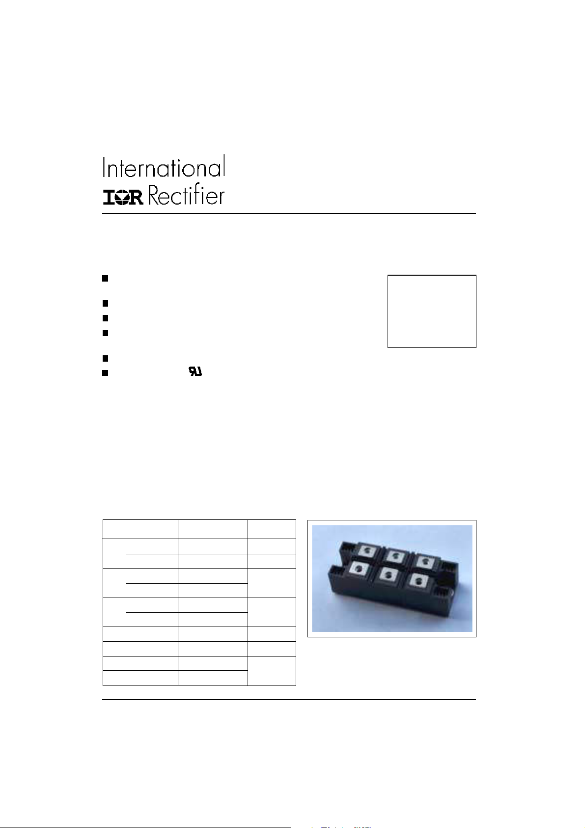
200MT40KB
THREE PHASE BRIDGE
Features
Package fully compatible with the industry standard INT-Apak power modules series
High thermal conductivity package, electrically insulated case
Low power loss
Excellent power volume ratio, outline for easy connections to
power transistor and IGBT modules
4000 V
UL E78996 approved
isolating voltage
RMS
Description
It extents the existing range of MT...KB bridges an
extremely compact, encapsulated three phase bridge
rectifiers offering efficient and reliable operation. They
are intended for use in general purpose and heavy duty
applications.
Major Ratings and Characteristics
Power Module
200 A
Parameters 200MT40KB Units
I
O
@ T
C
I
@ 50Hz 1800 A
FSM
@ 60Hz 1880
I2t @ 50Hz 16.2 KA2s
@ 60Hz 14.7
I2√t 162 KA2√s
V
RRM
T
range - 40 to 150 °C
STG
TJrange - 40 to 150
200 A
85 °C
400 V
Page 2
200MT40KB
Document Number: 93560
www.vishay.com
2
Bulletin I27129 rev. C 05/03
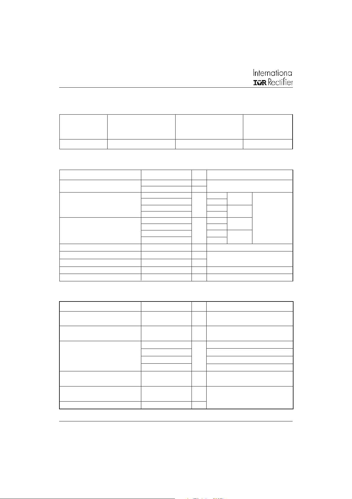
ELECTRICAL SPECIFICATIONS
Voltage Ratings
V
, maximum V
RRM
Type number repetitive peak non-repetitive peak @ T
reverse voltage reverse voltage
VVmA
200MT40KB 400 500 6
Forward Conduction
Parameter 200MT40KB Units Conditions
I
Maximum RMS output current 200 A 120° Rect conduction angle
O
@ Case temperature 85 °C
I
Maximum peak, one-cycle 1800 A t = 10ms No voltage
TSM
forward, non-repetitive 1880 t = 8.3ms reapplied
on state surge current 1520 t = 10ms 100% V
2
I
t Maximum I2 t for fusing 16.2 KA2s t = 10ms No voltage TJ = TJ max.
2
√t Maximum I2√t for fusing 162 KA2√s t = 0.1 to 10ms, no voltage reapplied
I
Value of threshold voltage 0.76 V @ TJ max.
V
F(TO)
r
Slope resistance 2.4 mΩ
t
V
Maximum forward voltage drop 1.40 V Ipk = 200A, TJ = 25°C, tp = 400µs single junction
FM
V
Insulation voltage 4000 V TJ = 25oC all terminal shorted, f = 50Hz, t = 1s
INS
1590 t = 8.3ms reapplied Initial
14.7 t = 8.3ms reapplied
11.6 t = 10ms 100% V
12.6 t = 8.3ms reapplied
, maximum I
RSM
RRM
RRM
RRM
J
= 150°C
max.
Thermal and Mechanical Specifications
Parameter 200MT40KB Units Conditions
TJMaximum junction operating - 40 to 150 °C
temperature range
T
Maximum storage temperature -40 to 150 °C
stg
range
Maximum thermal resistance, 0.12 K/W DC operation per module
R
thJC
junction to case 0.69 DC operation per junction
0.14 120° Rect condunction angle per module
0.82 120° Rect condunction angle per junction
R
Maximum thermal resistance, 0.033 K/W
thCS
case to heatsink
T Mounting torque ± 10% 4 to 6 Nm
to heatsink
wt Approximate weight 176 g
Per module.
Mounting surface smooth, flat and greased.
Heatsink compound thermal conductivity = 0.42W/mK
A mounting compound is recommended and the
torque should be rechecked after a period of 3
hours to allow for the spread of the compound.
Lubricated threads.
Page 3
Ordering Information Table
Document Number: 93560
www.vishay.com
3
Device Code
200MT40KB
Bulletin I27129 rev. C 05/03
20 0 MT 40 K B
1
1 - Current rating code: 20 = 200 A (Avg)
2 - Three phase diodes bridge
3 - Essential part number
4 - Voltage code: Code x 10 = V
5 - Generation II
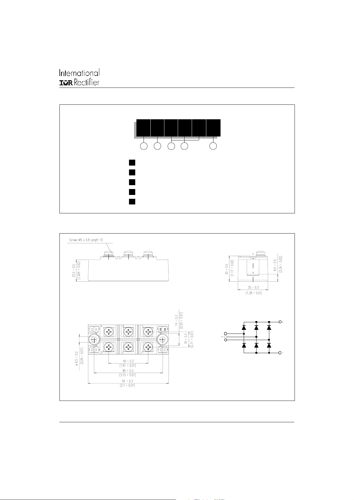
Outline Table (without optional barriers)
23
4
5
(40 = 400V)
RRM
D
A
B
C
E
F
All dimensions in millimeters (inches)
NOTE: To order the Optional Hardware see Bulletin I27900
Page 4

200MT40KB
Document Number: 93560
www.vishay.com
4
Bulletin I27129 rev. C 05/03
Outline Table (with optional barriers)
D
A
B
C
E
F
140
130
120
120˚
110
(Rect)
100
90
80
Maximum Allowable Case Temperature (°C)
70
60 80 100 120 140 160 180 200 220
Total Output Current (A)
Fig. 1 - Current Rating Characteristics
All dimensions in millimeters (inches)
1000
100
10
Instantaneous On-state Current (A)
1
0.5 1 1.5 2 2.5 3
Fig. 2 - On-state Voltage Drop Characteristics
Tj = 25˚C
Tj = 150˚C
Instantaneous On-state Voltage (V)
Page 5

200MT40KB
0
Document Number: 93560
www.vishay.com
5
Bulletin I27129 rev. C 05/03
1600
At Any Rated Load Condition And With
Rated Vrrm Applied Following Surge.
1400
1200
1000
Initial Tj = 150˚C
@ 60 Hz 0.0083 s
@ 50 Hz 0.0100 s
2000
Maximum Non Repetitive Surge Current
1800
1600
1400
1200
Versus Pulse Train Duration. Control
Of Conduction May Not Be Maintained.
No Voltage Reapplied
Rated V rrm Reapplied
1000
Initial T j = 150˚C
800
800
600
Per Junction
Peak Half Sine Wave On-state Current (A)
400
1 10 100
Number Of Equal Amplitude Half Cycle Current Pulses (N)
600
400
200
Per Junction
Peak Half Sine Wave On-state Current (A)
0
0.01 0.1 1 10
Pulse Train Duration(s)
Fig. 3 - Maximum Non-Repetitive Surge Current Fig. 4 - Maximum Non-Repetitive Surge Current
500
RthSA = 0.025 K/W - Delta R
0.05 K/W
0.1 K/W
400
0.2 K/W
0.3 K/W
0.5 K/W
1 K/W
300
200
100
120˚
(Rect)
Tj = 125˚C
Maximum Total Power Loss (W)
0
0 40 80 120 160 200
30 60 90 120 150
Maximum Allowable Ambient Temperature (°C)Total Output Current (A)
Fig. 5 - Current Rating Nomogram (1 Module Per Heatsink)
10
(K/W)
thJC
Steady State Value
RthJC per junction = 0.69 K/W
DC Operation)
1
0.1
0.01
Transient Thermal Impedance Z
0.0001 0.001 0.01 0.1 1 10
Square Wave Pulse Duration (s)
Fig. 6 - Thermal Impedance Z
Characteristics
thJC
Page 6

200MT40KB
Document Number: 93560
www.vishay.com
6
Bulletin I27129 rev. C 05/03
This product has been designed and qualified for Industrial Level.
Data and specifications subject to change without notice.
Qualification Standards can be found on IR's Web site.
IR WORLD HEADQUARTERS: 233 Kansas St., El Segundo, California 90245, USA Tel: (310) 252-7105
TAC Fax: (310) 252-7309
05/03
Page 7

Legal Disclaimer Notice
Vishay
Notice
The products described herein were acquired by Vishay Intertechnology, Inc., as part of its acquisition of
International Rectifier’s Power Control Systems (PCS) business, which closed in April 2007. Specifications of the
products displayed herein are pending review by Vishay and are subject to the terms and conditions shown below.
Specifications of the products displayed herein are subject to change without notice. Vishay Intertechnology, Inc., or
anyone on its behalf, assumes no responsibility or liability for any errors or inaccuracies.
Information contained herein is intended to provide a product description only. No license, express or implied, by
estoppel or otherwise, to any intellectual property rights is granted by this document. Except as provided in Vishay's
terms and conditions of sale for such products, Vishay assumes no liability whatsoever, and disclaims any express
or implied warranty, relating to sale and/or use of Vishay products including liability or warranties relating to fitness
for a particular purpose, merchantability, or infringement of any patent, copyright, or other intellectual property right.
The products shown herein are not designed for use in medical, life-saving, or life-sustaining applications.
Customers using or selling these products for use in such applications do so at their own risk and agree to fully
indemnify Vishay for any damages resulting from such improper use or sale.
International Rectifier
are registered trademarks of International Rectifier Corporation in the U.S. and other countries. All other product
names noted herein may be trademarks of their respective owners.
®
, IR®, the IR logo, HEXFET®, HEXSense®, HEXDIP®, DOL®, INTERO®, and POWIRTRAIN
®
Document Number: 99901 www.vishay.com
Revision: 12-Mar-07 1
 Loading...