

Page 1
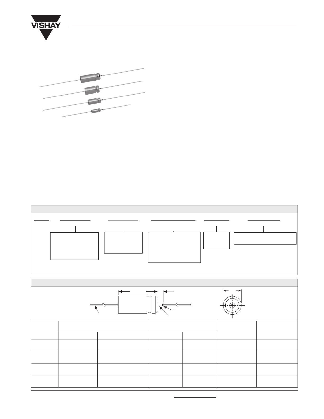
Wet Tantalum Capacitors
Sintered Anode TANTALEX
®
with True Glass-to-Tantalum Seal
PERFORMANCE CHARACTERISTICS
Operating Temperature: - 55°C to + 85°C and with
voltage derating to two-thirds the + 85°C rating at + 125°C.
Use of Type 138D capacitors for high temperature
applications is recommended.
Capacitance Tolerance: At 120Hz, + 25°C. ± 20% standard.
± 10%, ± 5% available as special.
DC Leakage Current (DCL Max.):
At + 25°C, + 85°C and + 125°C: Leakage current shall not
exceed the values listed in the Standard Ratings Tables.
Life Test: Capacitors are capable of withstanding a 2000
hour life test at a temperature of + 85°C or + 125°C at the
applicable rated DC working voltage.
138D
Vishay
Capacitors Hermetically-Sealed
FEATURES
Improved reliability through the use of a glass-to-tantalum
true hermetic anode seal is the prime feature of the Type
138D sintered anode T
ANTALEX
offers outstanding resistance to thermal shock.
Model 138D is the commercial equivalents of Tansitor Styles
WT, UWT, Mallory-NACC Styles TLX, TXX and Military Styles
CL66, CL67, CLR65, and CLR69, designed to meet the
performance requirements of Military Specification MIL-PRF39006/09/21. Capacitors in accordance with military
specifications should be ordered by their military part
numbers.
Following the life test:
1. DCL shall not exceed 125% of the original requirement.
2. The ESR shall not exceed 200% of the initial requirement.
3. Change in capacitance value shall not exceed the
percentages below.
a) 6WVDC Units: + 10% to - 25% of initial measurement.
b) 8WVDC and 10WVDC Units: + 10% to - 20% of initial
measurement.
c) 15WVDC Units: + 10% to - 15% of initial measurement.
d) 20WVDC and above: ± 10% of initial measurement.
®
capacitor. This construction
ORDERING INFORMATION
138D
MODEL
This is expressed in
picofarads. The first two
digits are the significant
figures. The third is the
Packaging: The use of formed plastic trays for packaging these axial lead components is standard. Tape and reel is not recommended
due to the unit weight.
306
CAPACITANCE
number of zeros to
follow.
X0
CAPACITANCE
TOLERANCE
X0 = ± 20%
X9 = ± 10%
X5 = ± 5%
Special Order.
DC VOLTAGE RATING
This is expressed in volts.
To complete the three-digit
block, zeros precede the
voltage rating. A decimal
point is indicated by an "R"
006
AT + 85°C
(6R3 = 6.3 volts).
C
CASE CODE
See Ratings
and Case
Codes Table.
2
STYLE NUMBER
0 = No outer tube.
2 = Outer plastic-film insulation.
DIMENSIONS in inches [millimeters]
0.0253 ± 0.002 [0.64 ± 0.05] Dia.
(No. 22 AWG) Tinned Solderable Leads
CASE
CODE
C
F
T
K
D
0.188 ± 0.016
[4.78 ± 0.41]
0.281 ± 0.016
[7.14 ± 0.41]
0.375 ± 0.016
[9.53 ± 0.41]
0.375 ± 0.016
[9.53 ± 0.41]
BARE TUBE
0.453 + 0.031 - 0.016
[11.51 + 0.79 - 0.41]
0.641 + 0.031 - 0.016
[16.28 + 0.79 - 0.41]
0.766 + 0.031 - 0.016
[19.46 + 0.79 - 0.41]
1.062 + 0.031 - 0.023
[26.97 + 0.79 - 0.58]
L
PLASTIC - FILM INSULATION
L
D (Max.)
0.219
[5.56]
0.312
[7.92]
0.406
[10.31]
0.406
[10.31]
0.250 [6.35]
Max.
Weld
Tantalum
WITH OUTER
L (Max.)
0.608
[15.45]
0.796
[20.22]
0.921
[23.40]
1.127
[30.91]
D
LEAD
LENGTH
1.500 ± 0.250
[38.10 ± 6.35]
2.250 ± 0.250
[57.15 ± 6.35]
2.250 ± 0.250
[57.15 ± 6.35]
2.250 ± 0.250
[57.15 ± 6.35]
Max. WEIGHT
(Ounces/Grams)
0.07
[2.0]
0.18
[5.1]
0.36
[10.2]
0.49
[13.9]
Document Number: 40025
Revision 15-Oct-03
For technical questions, contact wettants@vishay.com
www.vishay.com
55
Page 2
138D
Vishay
Sintered Anode TANTALEX
STANDARD RATINGS
CAPACITANCE
(µF)
30
68
140
270
330
560
1200
25
56
220
430
850
CASE
CODE
C
C
F
F
T
T
K
C
C
F
T
K
with True Glass-to-Tantalum Seal
PART NUMBER*
138D306X0006C2
138D686X0006C2
138D147X0006F2
138D277X0006F2
138D337X0006T2
138D567X0006T2
138D128X0006K2
138D256X0008C2
138D566X0008C2
138D227X0008F2
138D437X0008T2
138D857X0008K2
Wet Tantalum Capacitors
®
Capacitors Hermetically-Sealed
Max. ESR
at + 25°C
(Ohms)
6WVDC at + 85°C . . . 4WVDC at + 125°C
4
4
2
4
2
3
1.6
8WVDC at + 85°C . . . 5WVDC at + 125°C
4
4
4
3
1
10WVDC at + 85°C . . . 7WVDC at + 125°C
Max. IMP.
at - 55°C
(Ohms)
100
60
40
25
20
25
20
100
59
30
25
22
Max. DCL (µA) at
+ 25°C- 55°C+ 85°C + 125°C
1
1
1
1
2
2
3
1
1
1
2
4
+ 85°C
+ 125°C
2
2
3
6.5
7.9
13
14
2
2
7
14
16
Max. CAPACITANCE
CHANGE (%) at
- 40
- 40
- 40
- 44
- 44
- 64
- 80
- 40
- 40
- 44
- 64
- 80
+ 10.5
+ 14
+ 14
+ 17.5
+ 14
+ 17.5
+ 25
+ 10.5
+ 14
+ 17.5
+ 17.5
+ 25
+ 12
+ 16
+ 16
+ 20
+ 16
+ 20
+ 25
+ 12
+ 16
+ 20
+ 20
+ 25
20
47
100
180
250
390
750
15
33
70
120
170
270
540
27
220
10
22
50
100
180
350
8.0
15
40
100
150
300
C
C
F
F
T
T
K
C
C
F
F
T
T
K
C
T
C
C
F
F
T
K
C
C
F
T
T
K
138D206X0010C2
138D476X0010C2
138D107X0010F2
138D187X0010F2
138D257X0010T2
138D397X0010T2
138D757X0010K2
138D156X0015C2
138D336X0015C2
138D706X0015F2
138D127X0015F2
138D177X0015T2
138D277X0015T2
138D547X0015K2
138D276X0020C2
138D227X0020T2
138D106X0025C2
138D226X0025C2
138D506X0025F2
138D107X0025F2
138D187X0025T2
138D357X0025K2
138D805X0030C2
138D156X0030C2
138D406X0030F2
138D107X0030T2
138D157X0030T2
138D307X0030K2
4
5
2
4
2
3
1
15WVDC at + 85°C . . . 10WVDC at + 125°C
5
5
4
4
2
3
1.0
20WVDC at + 85°C . . . 13WVDC at + 125°C
5
4
25WVDC at + 85°C . . . 15WVDC at + 125°C
6
5
4
4
4
1.3
30WVDC at + 85°C . . . 20WVDC at + 125°C
7.5
8
4
6
2.5
1.6
175
100
60
40
30
25
23
155
90
75
50
35
30
23
100
30
220
140
70
50
32
24
275
175
65
40
35
25
1
1
1
1
2
2
4
1
1
1
1
2
2
6
1
2
1
1
1
1
2
7
1
1
1
2
2
8
10
16
16
10
16
24
16
2
10
18
28
2
2
4
7
2
2
4
7
2
2
5
2
2
5
12
16
32
- 32
- 36
- 36
- 36
- 40
- 64
- 80
- 24
- 28
- 28
- 28
- 32
- 56
- 80
- 20
- 48
- 16
- 20
- 28
- 28
- 48
- 70
- 16
- 20
- 24
- 28
- 48
- 60
+ 10.5
+ 14
+ 14
+ 14
+ 14
+ 17.5
+ 25
+ 10.5
+ 14
+ 14
+ 17.5
+ 14
+ 17.5
+ 25
+ 11
+ 13
+ 8
+ 10.5
+ 13
+ 13
+ 13
+ 25
+ 8
+ 10.5
+ 10.5
+ 10.5
+ 13
+ 25
+ 12
+ 16
+ 16
+ 16
+ 16
+ 20
+ 25
+ 12
+ 16
+ 16
+ 20
+ 16
+ 20
+ 25
+ 14
+ 15
+ 9
+ 12
+ 15
+ 15
+ 15
+ 25
+ 12
+ 12
+ 12
+ 12
+ 15
+ 25
www.vishay.com
56
For technical questions, contact wettants@vishay.com
Document Number: 40025
Revision 15-Oct-03
Page 3
138D
Sintered Anode TANTALEX® Capacitors Hermetically-Sealed
STANDARD RATINGS
CAPACITANCE
(µF) PART NUMBER*
68
120
270
5.0
10
25
47
60
82
160
4.0
8.2
20
39
50
68
140
CASE
CODE
F
T
K
C
C
F
F
T
T
K
C
C
F
F
T
T
K
138D686X0035F2
138D127X0035T2
138D277X0035K2
138D505X0050C2
138D106X0050C2
138D256X0050F2
138D476X0050F2
138D606X0050T2
138D826X0050T2
138D167X0050K2
138D405X0060C2
138D825X0060C2
138D206X0060F2
138D396X0060F2
138D506X0060T2
138D686X0060T2
138D147X0060K2
Wet Tantalum Capacitors
with True Glass-to-Tantalum Seal
Max. ESR
at + 25
(Ohms)
35WVDC at + 85°C . . . 22WVDC at + 125°C
2.2
50WVDC at + 85°C . . . 30WVDC at + 125°C
2.2
60WVDC at + 85°C . . . 40WVDC at + 125°C
10
2.4
Max. IMP.
°C
at - 55
°C
(Ohms)
6
4
9
8
6
6
3
4
8
5
7
4
6
60
38
23
400
250
95
70
45
45
27
550
275
105
90
50
50
28
Max. DCL (µA) at
+ 85
°C
+ 25
+ 125°C
1
2
8
1
1
1
1
2
2
8
1
1
1
1
2
2
8
16
32
12
16
32
12
16
32
Vishay
Max. CAPACITANCE
CHANGE (%) at
°C
8
2
2
5
9
2
2
5
9
- 24
- 30
- 45
- 16
- 24
- 20
- 28
- 16
- 32
- 50
- 16
- 24
- 16
- 28
- 16
- 32
- 40
+ 12
+ 13
+ 20
+ 5
+ 8
+ 10.5
+ 10.5
+ 10.5
+ 13
+ 25
+ 10.5
+ 10.5
+ 10.5
+ 10.5
+ 20
+ 5
+ 8
+ 125°C+ 85°C- 55°C
+ 15
+ 15
+ 25
+ 6
+ 9
+ 12
+ 15
+ 12
+ 15
+ 25
+ 6
+ 9
+ 12
+ 12
+ 12
+ 12
+ 20
75WVDC at + 85°C . . . 50WVDC at + 125°C
3.5
6.8
15
33
40
56
110
2.5
4.7
11
22
30
43
86
1.7
3.6
9.0
14
18
25
56
*Part Numbers listed are for units with outer plastic-film insulation and a capacitance tolerance of ± 20%. For bare case units, substitute "0"
for "2" at the end of the Part Number. For capacitors with ± 10% tolerance, change the digit following the letter "X" to "9".
C
C
F
F
T
T
K
C
C
F
F
T
T
K
C
C
F
F
T
T
K
138D355X0075C2
138D685X0075C2
138D156X0075F2
138D336X0075F2
138D406X0075T2
138D566X0075T2
138D117X0075K2
100WVDC at + 85°C . . . 65WVDC at + 125°C
138D255X0100C2
138D475X0100C2
138D116X0100F2
138D226X0100F2
138D306X0100T2
138D436X0100T2
138D866X0100K2
125WVDC at + 85°C . . . 85WVDC at + 125°C
138D175X0125C2
138D365X0125C2
138D905X0125F2
138D146X0125F2
138D186X0125T2
138D256X0125T2
138D566X0125K2
10
8
6.5
7
5
6
3.1
26.5
10
6
7
4
6
3.1
54.6
15
15
12
11
10
4.1
650
300
150
90
60
60
29
950
500
200
100
80
70
30
1250
600
240
167
129
93
32
1
1
1.0
1.0
2.0
2.0
9
1.0
1.0
1.0
1.0
2.0
2.0
9
1.0
1.0
1.0
1.0
2.0
2.0
10
2
2
5
10
12
17
36
2
2
4
9
12
17
36
2
2
5
7
9
13
40
- 16
- 20
- 16
- 24
- 16
- 28
- 35
- 16
- 16
- 16
- 16
- 16
- 20
- 25
- 16
- 16
- 16
- 16
- 16
- 16
- 25
+ 5
+ 8
+ 8
+ 10.5
+ 10.5
+ 10.5
+ 20
+ 7
+ 7
+ 7
+ 7
+ 7
+ 7
+ 15
+ 7
+ 7
+ 7
+ 7
+ 7
+ 7
+ 15
+ 6
+ 9
+ 9
+ 15
+ 12
+ 15
+ 20
+ 8
+ 8
+ 8
+ 8
+ 8
+ 8
+ 15
+ 8
+ 8
+ 8
+ 8
+ 8
+ 8
+ 15
Document Number: 40025
Revision 15-Oct-03
For technical questions, contact wettants@vishay.com
www.vishay.com
57
Page 4

138D
Vishay
Sintered Anode TANTALEX® Capacitors Hermetically-Sealed
EXTENDED RATINGS
CAPACITANCE
(µF)
560
820
1500
2200
180
470
680
1800
100
150
390
560
1200
1500
68
100
270
390
540
820
1000
56
82
220
330
47
68
180
270
350
CASE
CODE
F
F
T
K
C
F
F
K
C
C
F
F
T
K
C
C
F
F
T
T
K
C
C
F
F
C
C
F
F
T
with True Glass-to-Tantalum Seal
PART NUMBER*
138D567X0006F2
138D827X0006F2
138D158X0006T2
138D228X0006K2
138D187X0008C2
138D477X0008F2
138D687X0008F2
138D188X0008K2
138D107X0010C2
138D157X0010C2
138D397X0010F2
138D567X0010F2
138D128X0010T2
138D158X0010K2
138D686X0015C2
138D107X0015C2
138D277X0015F2
138D397X0015F2
138D547X0015T2
138D827X0015T2
138D108X0015K2
138D566X0020C2
138D826X0020C2
138D227X0020F2
138D337X0020F2
25 WVDC at + 85°C . . . 15 WVDC at + 125°C
138D476X0025C2
138D686X0025C2
138D187X0025F2
138D277X0025F2
138D357X0025T2
Wet Tantalum Capacitors
Max. ESR
at + 25°C
(Ohms)
6WVDC at + 85
2.5
2.5
1.5
1
8WVDC at + 85°C . . . 5WVDC at + 125°C
2.5
2.5
10WVDC at + 85°C . . . 7WVDC at + 125°C
15WVDC at + 85°C . . . 10WVDC at + 125°C
20WVDC at + 85°C . . . 13WVDC at + 125°C
Max. IMP.
at - 55°C
(Ohms)
°C . . . 4WVDC at + 125°C
20
18
18
13
3
1
3.0
3
2.5
2.5
1.5
1
4
4
2.5
2.5
1.8
1.8
1.2
4.3
4.3
2.7
2.7
4.3
4.3
2.7
2.7
1.8
45
25
22
14
60
54
30
27
18
15
80
72
35
31
25
22
17
90
81
35
31
100
90
37
33
27
Max. DCL (µA) at
+ 25°C
3
3
5
6
2
3
3
7
2
2
3
3
5
7
2
2
3
3
6
6
8
2
2
3
3
2
2
3
3
7
+ 85°C
+ 125°C
14
14
20
24
9
14
14
25
9
9
16
16
20
25
9
9
16
16
24
24
32
9
9
16
16
9
9
16
16
28
Max. CAPACITANCE
CHANGE (%) at
- 50
- 55
- 70
- 77
- 88
- 88
- 40
- 44
- 60
- 16
- 70
- 77
- 77
- 38
- 43
- 60
- 66
- 35
- 40
- 55
- 62
- 60
+ 85°C
+ 16
+ 16
+ 20
+ 25
+ 13
+ 16
+ 16
+ 20
+ 13
+ 13
+ 16
+ 16
+ 20
+ 25
+ 13
+ 13
+ 16
+ 16
+ 20
+ 20
+ 25
+ 13
+ 13
+ 16
+ 16
+ 12
+ 12
+ 13
+ 13
+ 20
- 55°C
- 80
- 88
- 90
- 90
- 60
- 75
- 83
- 90
+ 125°C
+ 20
+ 20
+ 25
+ 30
+ 16
+ 20
+ 20
+ 30
+ 16
+ 16
+ 20
+ 20
+ 25
+ 30
+ 16
+ 16
+ 20
+ 20
+ 25
+ 25
+ 30
+ 16
+ 16
+ 20
+ 20
+ 15
+ 15
+ 16
+ 16
+ 25
30WVDC at + 85°C . . . 20WVDC at + 125°C
39
56
150
220
330
470
560
* Part Numbers listed are for units with outer plastic-film insulation and a capacitance tolerance of ± 20%. For bare case units, substitute "0"
for "2" at the end of the Part Number. For capacitors with ± 10% tolerance, change the digit following the letter "X" to "9".
www.vishay.com
58
C
C
F
F
T
T
K
138D396X0030C2
138D566X0030C2
138D157X0030F2
138D227X0030F2
138D337X0030T2
138D477X0030T2
138D567X0030K2
For technical questions, contact wettants@vishay.com
5.2
5.2
2.5
2.5
1.8
1.8
1.3
110
100
40
36
28
25
20
2
2
3
3
8
8
9
16
16
32
32
36
9
9
- 32
- 38
- 50
- 60
- 50
- 65
- 65
+ 12
+ 12
+ 13
+ 13
+ 20
+ 20
+ 25
Document Number: 40025
Revision 15-Oct-03
+ 15
+ 15
+ 16
+ 16
+ 25
+ 25
+ 30
Page 5

138D
Wet Tantalum Capacitors
Sintered Anode TANTALEX
®
Capacitors Hermetically-Sealed
Vishay
with True Glass-to-Tantalum Seal
EXTENDED RATINGS
Max. CAPACITANCE
CHANGE (%) at
- 30
- 35
- 45
- 45
- 58
- 58
- 24
- 29
- 35
- 42
- 35
- 46
- 46
- 20
- 24
- 30
- 36
- 30
- 40
- 45
- 16
- 19
- 25
- 30
- 25
- 35
- 40
- 12
- 17
- 18
- 20
- 30
- 35
- 14
- 18
- 16
- 26
- 30
+ 10
+ 10
+ 13
+ 20
+ 20
+ 25
+ 10
+ 10
+ 10
+ 12
+ 20
+ 20
+ 25
+ 10
+ 10
+ 12
+ 12
+ 16
+ 16
+ 20
+ 10
+ 10
+ 12
+ 12
+ 16
+ 16
+ 20
+ 10
+ 10
+ 12
+ 12
+ 14
+ 15
+ 10
+ 12
+ 14
+ 14
+ 15
+ 125°C+ 85°C- 55°C
+ 12
+ 12
+ 16
+ 25
+ 25
+ 30
+ 12
+ 12
+ 15
+ 15
+ 25
+ 25
+ 30
+ 12
+ 12
+ 15
+ 15
+ 20
+ 20
+ 25
+ 12
+ 12
+ 15
+ 15
+ 20
+ 20
+ 25
+ 12
+ 12
+ 15
+ 15
+ 16
+ 17
+ 12
+ 15
+ 16
+ 16
+ 17
°C
55
49
32
29
22
Max. DCL (µA) at
+ 85°C
°C
+ 25
10
10
12
3
3
4
4
9
9
3
3
5
5
10
10
12
+ 125°C
2
2
3
8
8
9
2
2
4
4
6
8
9
3
3
4
4
8
8
9
3
5
16
32
32
36
9
9
24
24
32
32
36
12
12
20
20
32
32
36
12
12
24
24
36
36
40
12
12
24
24
40
48
12
24
40
40
48
9
9
Max. ESR
CAPACITANCE
(µF)
33
47
120
220
390
470
22
33
82
120
160
270
330
18
27
68
100
140
220
270
15
22
56
82
110
180
220
8.2
10
33
39
68
120
6.8
27
39
47
82
*Part Numbers listed are for units with outer plastic-film insulation and a capacitance tolerance of ± 20%. For bare case units, substitute "0"
for "2" at the end of the Part Number. For capacitors with ± 10% tolerance, change the digit following the letter "X" to "9".
CASE
CODE
C
C
F
T
T
K
C
C
F
F
T
T
K
C
C
F
F
T
T
K
C
C
F
F
T
T
K
C
C
F
F
T
K
C
F
T
T
K
138D336X0035C2
138D476X0035C2
138D127X0035F2
138D227X0035T2
138D397X0035T2
138D477X0035K2
138D226X0050C2
138D336X0050C2
138D826X0050F2
138D127X0050F2
138D167X0050T2
138D277X0050T2
138D337X0050K2
138D186X0060C2
138D276X0060C2
138D686X0060F2
138D107X0060F2
138D147X0060T2
138D227X0060T2
138D277X0060K2
138D156X0075C2
138D226X0075C2
138D566X0075F2
138D826X0075F2
138D117X0075T2
138D187X0075T2
138D227X0075K2
100WVDC at + 85°C . . . 65WVDC at + 125°C
138D825X0100C2
138D106X0100C2
138D336X0100F2
138D396X0100F2
138D686X0100T2
138D127X0100K2
138D685X0125C2
138D276X0125F2
138D396X0125T2
138D476X0125T2
138D826X0125K2
at + 25°C
(Ohms)PART NUMBER*
35WVDC at + 85°C . . . 22WVDC at + 125°C
5.2
5.2
2.5
1.8
1.8
1.3
50WVDC at + 85°C . . . 30WVDC at + 125°C
2.5
2.5
1.8
1.8
1.5
60WVDC at + 85°C . . . 40WVDC at + 125°C
2.5
1.8
1.5
75WVDC at + 85°C . . . 50WVDC at + 125°C
5
5
3
2.5
2
1.8
2.2
6
6
3.5
3.5
2.2
2.8
125WVDC at + 85°C . . . 85WVDC at + 125°C
11.7
3.5
2.2
2.2
2.8
Max. IMP.
at - 55
(Ohms)
130
115
45
30
27
21
5
5
5
5
3
2
150
135
160
144
60
54
32
29
23
175
157
70
63
33
30
24
250
200
85
80
40
30
300
90
60
50
32
Document Number: 40025
Revision 15-Oct-03
For technical questions, contact wettants@vishay.com
www.vishay.com
59
Page 6

138D
Vishay
Sintered Anode TANTALEX
Wet Tantalum Capacitors
®
Capacitors Hermetically-Sealed
with True Glass-to-Tantalum Seal
TYPICAL CURVES OF IMPEDANCE AS A FUNCTION OF FREQUENCY AT VARIOUS TEMPERATURES
“K” Case 120µF, 25V Capacitors
200
100
10
- 55°C
IMPEDANCE IN OHMS
1.0
+125°C
0.2
100 1K 10K 100K 1M 10M
+ 85°C
FREQUENCY IN HERTZ
- 40°C
- 20°C
+ 25°C
PERFORMANCE CHARACTERISTICS
1. Operating Temperature: Capacitors are designed to
operate over the temperature range of - 55°C to
+125°C.
UP TO + 85°C AT + 125°C UP TO + 85°C AT + 125°C
WORKING WORKING WORKING WORKING
VOLTAGE VOLTAGE VOLTAGE VOLTAGE
(V) (V) (V) (V)
6 4 35 22
8 5 50 30
10 7 60 40
15 10 75 50
20 13 100 70
25 15 125 85
30 20 150 100
2. DC Working Voltage: The DC working voltage is the
maximum operating voltage for continuous duty at the
rated temperature.
3. Surge Voltage: The surge DC rating is the maximum
voltage to which the capacitors should be subjected
under any conditions. This includes transients and
peak ripple at the highest line voltage. The surge
voltage of capacitors rated below 150 volts is 115% of
the rated DC working voltage. The surge voltage of
capacitors rated at 150 volts DC is 165 volts.
3.1 Surge Voltage Test: Capacitors shall withstand the
surge voltage test applied through a 1000 ohm ± 10%
resistor in series with the capacitor and voltage source
at the rate of one-half minute on, four and one-half
minutes off, for 1000 successive test cycles at + 85°C
or + 125°C.
4. Capacitance Tolerance: The capacitance of all
capacitors shall be within the specified tolerance limits
of the nominal rating.
200
100
10
IMPEDANCE IN OHMS
1.0
0.2
100 1K 10K 100K 1M 10M
4.1 Capacitance measurements shall be made by the
bridge method at or referred to, a frequency of 120Hz
at a temperature of + 25°C. A polarizing voltage shall
be used of such magnitude that there shall be no
reversal of polarity due to the AC component. The
maximum AC voltage will be 1 volt rms applied during
measurement.
5. Capacitance Change With Temperature: The
capacitance change with temperature shall not exceed
the limits given in the Standard and Extended Ratings
Table for each capacitor.
6. Equivalent Series Resistance: Measurements shall
be made by the bridge method at or referred to, a
frequency of 120Hz at a temperature of + 25°C. A
polarizing voltage shall be used of such magnitude that
there shall be no reversal of polarity due to the AC
component. The maximum AC voltage will be 1 volt
rms applied during measurement.
6.1. The equivalent series resistance shall not exceed the
maximum value in ohms listed in the Standard and
Extended Ratings Table for each capacitor.
6.2. The dissipation factor may be calculated from the
equivalent series resistance and capacitance values
as shown:
where:
“C” Case 10µF. 100V Capacitors
+125°C
FREQUENCY IN HERTZ
+ 85°C
DF = 2πfRC
4
10
DF = Dissipation Factor in %
R = ESR in ohms
C = Capacitance in µF
f = frequency in Hz
- 55°C
- 40°C
- 20°C
+ 25°C
www.vishay.com
60
For technical questions, contact wettants@vishay.com
Document Number: 40025
Revision 15-Oct-03
Page 7

138D
Wet Tantalum Capacitors
Sintered Anode TANTALEX
with True Glass-to-Tantalum Seal
PERFORMANCE CHARACTERISTICS (Cont’d)
At 120Hz, the above equation becomes:
DF = R x C
13.26
For example, percent dissipation factor of a 30µF, 6
volt capacitor, which has a maximum ESR of 3.4 ohms
at + 25°C and 120Hz, would be calculated as shown:
DF = 2π x 120 x 3.4 x 30
7. Leakage Current: Measurements shall be made at
the applicable rated working voltage at + 25°C ± 5°C
through application of a steady source of power, such
as a regulated power supply. The total resistance in
series with each capacitor shall be between 1000 ohms
and 10,000 ohms. The voltage shall be applied to the
capacitor for 5 minutes before making the leakage
current measurement.
7.1. The maximum leakage current for any capacitor shall
not exceed the value in microamperes listed in the
Standard and Extended Ratings Table for each
capacitor.
Note: leakage current varies with applied voltage. See graph below
for the appropriate adjustment factor.
10
4
LEAKAGE AS A FUNCTION OF VOLTAGE &
TEMPERATURE
Leakage Current Factor
Percent of Rated Voltage
8. Low Temperature Impedance: The impedance of any
capacitor at - 55°C at 120Hz, shall not exceed the
values given in the Standard and Extended Ratings
Tables.
=
3.4 x 30
13.26
= 7.7%
®
Capacitors Hermetically-Sealed
9. Life Test: Capacitors are capable of withstanding a
2000 hour life test at a temperature of + 85°C or
+ 125°C at the applicable rated DC working voltage.
10. High Frequency Vibration: Capacitors shall with
stand vibration from 10Hz to 2000Hz at 20g when
tested.
11. Lead Pull Test: Capacitors shall withstand a lead
tensile stress of 3 pounds (13.2N) for 30 seconds,
applied axially.
12. Marking: Capacitors shall be marked with Sprague
and/or the Sprague® trademark 2, the Sprague® type
(138D); rated capacitance and tolerance (the tolerance
shall be coded, using the list shown in How to Order);
rated DC working voltage at + 85°C; the standard EIA
date code of manufacture.
GUIDE TO APPLICATION
1. Ripple Current: All capacitors will withstand rms ripple
currents as listed for each capacitor.
1.1. The rms ripple current rating is independent of
temperature or frequency within the following
limitations:
1.1.1.At frequencies of less than 120Hz, the rated rms ripple
current must be multiplied by the factors shown:
FREQUENCY IN HERTZ
25 50 60 100
0.36 0.59 0.65 0.88
1.1.2 The sum of the peak AC voltage plus the DC voltage
shall not exceed the DC working voltage of the
capacitor.
1.1.3 The sum of the negative peak AC voltage, plus the
applied DC voltage shall not allow a voltage reversal.
2. Cleaning wiring boards with Type 138D capacitors:
Customary cleaning solvents used in the electronics
industry at present will not affect Type 138D capacitors.
However, the use of ultrasonic cleaning techniques is
not recommended under any circumstances.
3. Apparent Capacitance: Note that in timing circuit
applications, the circuit designer must take into account
two important variables which affect any electrolytic
capacitor. These are the internal leakage resistance
of the capacitor and its dielectric absorption, which will
depend on the elapsed time since the capacitor was
last energized.
In applications where electrolytic capacitors are
subjected to DC energy, or in effect, extremely low
frequencies, the value of the apparent capacitance will
be somewhat higher than that which is measured at
120HZ.
4. No Reverse Voltage: The application of reverse
voltage to these capacitors will cause internal damage.
The resulting damage will lead to immediate or delayed
failure of the unit. This will take the form of a
catastrophic short circuit with possible expulsion of the
electrolyte.
Vishay
®
Document Number: 40025
Revision 15-Oct-03
For technical questions, contact wettants@vishay.com
www.vishay.com
61
 Loading...