

Page 1
•
•
•
•
110E
Vishay Spectrol
Mechanical Encoder
FEATURES
Cost Effective - Eliminates A/D Converters
High Resolution - Up to 36 Positions
Stability - Operating Range of - 40°C to + 105°C
Variability - Horizontal and Vertical Mounting
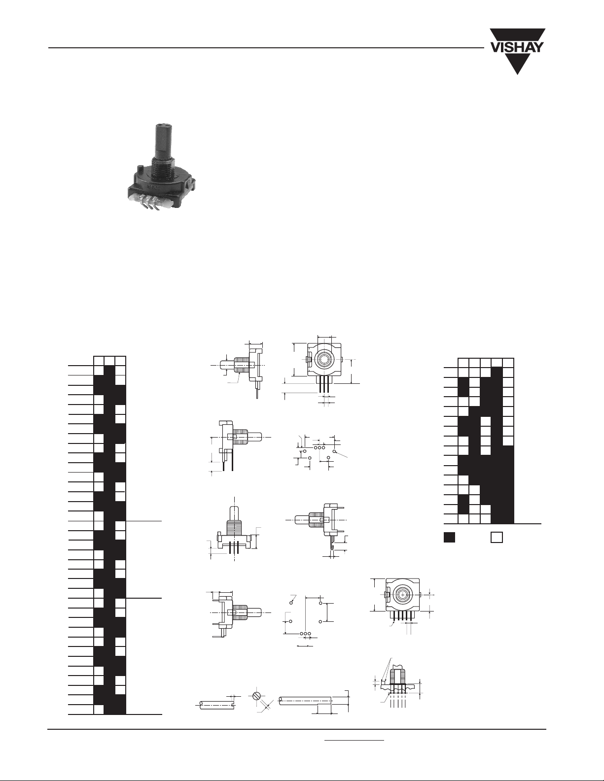
The Model 110E is a 7/8” square mechanical encoder which
provides a 2 - bit grey code for relative reference and a 4 - bit
grey code for absolute reference applications. Manually
operated it has a rotational life of 100,000 shaft revolutions,
a positive dentent feel and can be combined with a second
DIMENSIONS in inches
2 - BIT, 36 - POSITION
INCREMENTAL OUTPUT
STEP
1
G2
1
2
3
4
5
6
7
8
9
10
11
12
13
14
15
16
17
18
19
20
21
22
23
24
25
26
27
28
29
30
31
32
33
34
35
36
2 - BIT
16 POS.
2 - BIT
24 POS.
2 - BIT
36 POS.
PC TERMINALS
TYPE B - 110
+ 0.002
0.250 - 0.001
3/8 - 32 UNEF - 2A
0.625
0.245
PC TERMINALS
TYPE C - 30
0.156
0.156
± 0.005
0.068
0.343
0.830 ± 0.005
TYPE “B” MTG
WITH BRACKET
0.343
SOLDER HOOK
TERMINALS
(ON 0.200 SPACING)
0.363
TYPE “C” MTG
WITH BRACKET
SHAFT DIMENSIONS
FLATTED SHAFT
± 0.005
0.047
modular section in a concentric - shaft construction. Its small
size makes it suitable for panel-mounted applications where
the need for costly front - panel displays can be completely
eliminated.
SQUARE
0.250
0.050
(2X)
0.900
0.450
0.250
Ø.047
3/4”, 7/8”, F.M.S.
0.320
(2X)
0.600
0.100
0.100 (2X)
0.375
0.320
0.100 TYP
0.100 (2X)
0.100 (2X)
0.300
0.450 (2X)
0.600
(2X)
0.218
0.615
Ø.047
(7X)
0.200
REF
0.830 ± 0.005
SQUARE
0.020 X 0.025 THK
0.060
0.047 Ø
SUGGESTED
G8
2
4
1
0.005/0.010 R
0.206 ± 0.010
SUGGESTED
4 - BITS, 6 - POSITION
INCREMENTAL OUTPUT
STEP
142G8
1
2
3
4
5
6
7
8
9
10
11
12
13
14
15
16
Output Codes
At start position, step 1, is
with shaft flat at 12 o’ clock
position when looking at
shaft end with terminals down.
0.415
0.100 TYP
0.100 (2X)
4 - BIT
16 POS.
www.vishay.com For technical questions, contact: sf
er@vishay.com Document Number: 57089
136 Revision: 05-Aug-04
Page 2

5 Ω
48
P
110E
ELECTRICAL SPECIFICATIONS
Output
Closed Circuit Resistance
Open Circuit Resistance
Contact Rating
Switching Loads
Bounce
Dielectric Withstanding Voltage
Electrical Travel
Operating Speed
MECHANICAL SPECIFICATIONS
Rotational Torque
Mechanical Travel
Panel Mounting Torque
Shaft Load Force
Shaft Pull Force
Terminals
Molded Construction
Rotational Life
3.5 oz - in (2.16 - 3.60 Ncm)
Continuous
7 lbs - in (1.13 Nm) maximum
10 lbs - in (1.13 Nm) maximum
10 lbs - in maximum
Standard PC style, 3
terminals on 0.100”
(2.54mm) grid - in - line
perpendicular or parallel
to shaft. Solder hook
available on 0.200” grid
Molding compound
used for housing/bushing and
shaft has a UL94V - 2 rating
100,000 detented cycles
at rated load typical (1
cycle = 720 degrees)
Mechanical Encoder
2 - bit grey code, channel L leads channel R by 90
degrees electrically in the CW direction
4 bi - grey code, absolute electrical position output
ENVIRONMENTAL SPECIFICATIONS
Temperature Range
Humidity
Shock
PACKAGING
Box of 50 pieces
Vishay Spectrol
maximum
100K Ω minimum
Resistance load 250mA at 28VDC
1.5mA at 115VDC
150mA at 14VDC
5ms/cycle at 15 RPM
1000VAC at sea level
Continuous
50 RPM maximum
- 40°C to + 105°C
(Operating temperature)
- 55°C to + 120°C
(Storage temperature)
Per MIL-STD 202, Method
106C Insulation resistance
shall be 1 M Ω maximum of a
relative humidity 90% @ 25°C
Per MIL-STD 202,
Method 213, Test
Condition G consisting
of 1 MIL-STD
ORDERING INFORMATION
110E
MODEL
110E
1A
1 = at 9’0 clock
0 = None
BUSHING
A = 3/8 (9.53mm)
dia x 1/4 (6.35mm) long
G = 3/8 (9.53mm)
dia x 3/8 (9.53mm) long
SINGLE SHAFT FMS
CODED IN 64ths
48 = 0.750”
56 = 0.875”
F 204P
S:
Slotted
F:
Flatted
2-4 - BIT GREY
CODE OPTIONS
204P = 4 cycles/rev
206P = 6 cycles/rev
209P = 9 cycles/rev
416P = 16 electrical
16 detents/rev
24 detents/rev
36 detents/rev
positions/rev
16 detents/rev
B: PC terminals straight
(horizontal mount)
C: PC terminals bent back
(vertical mount)
Type C - 30
P: Type B with
mounting bracket
D: Type C with
mounting bracket
S: Solder Hook
Hardware not included
SAP PART NUMBERING GUIDELINES
110EW1GHFP2 0 4PB2 5
MODEL
See the end of this data book for conversion tables
Document Number: 57089 For technical questions, contact: sf
Revision: 05-Aug-04 137
BUSHING
PEG
SHAFT
LEADS
CODE OPTIONS
er@vishay.com www.vishay.com
PACKAGING
SPECIAL
Page 3

Legal Disclaimer Notice
Vishay
Notice
Specifications of the products displayed herein are subject to change without notice. Vishay Intertechnology, Inc.,
or anyone on its behalf, assumes no responsibility or liability for any errors or inaccuracies.
Information contained herein is intended to provide a product description only. No license, express or implied, by
estoppel or otherwise, to any intellectual property rights is granted by this document. Except as provided in Vishay's
terms and conditions of sale for such products, Vishay assumes no liability whatsoever, and disclaims any express
or implied warranty, relating to sale and/or use of Vishay products including liability or warranties relating to fitness
for a particular purpose, merchantability, or infringement of any patent, copyright, or other intellectual property right.
The products shown herein are not designed for use in medical, life-saving, or life-sustaining applications.
Customers using or selling these products for use in such applications do so at their own risk and agree to fully
indemnify Vishay for any damages resulting from such improper use or sale.
Document Number: 91000 www.vishay.com
Revision: 08-Apr-05 1
 Loading...