

FAST SOFT RECOVERY
Document Number: 94094
www.vishay.com
1
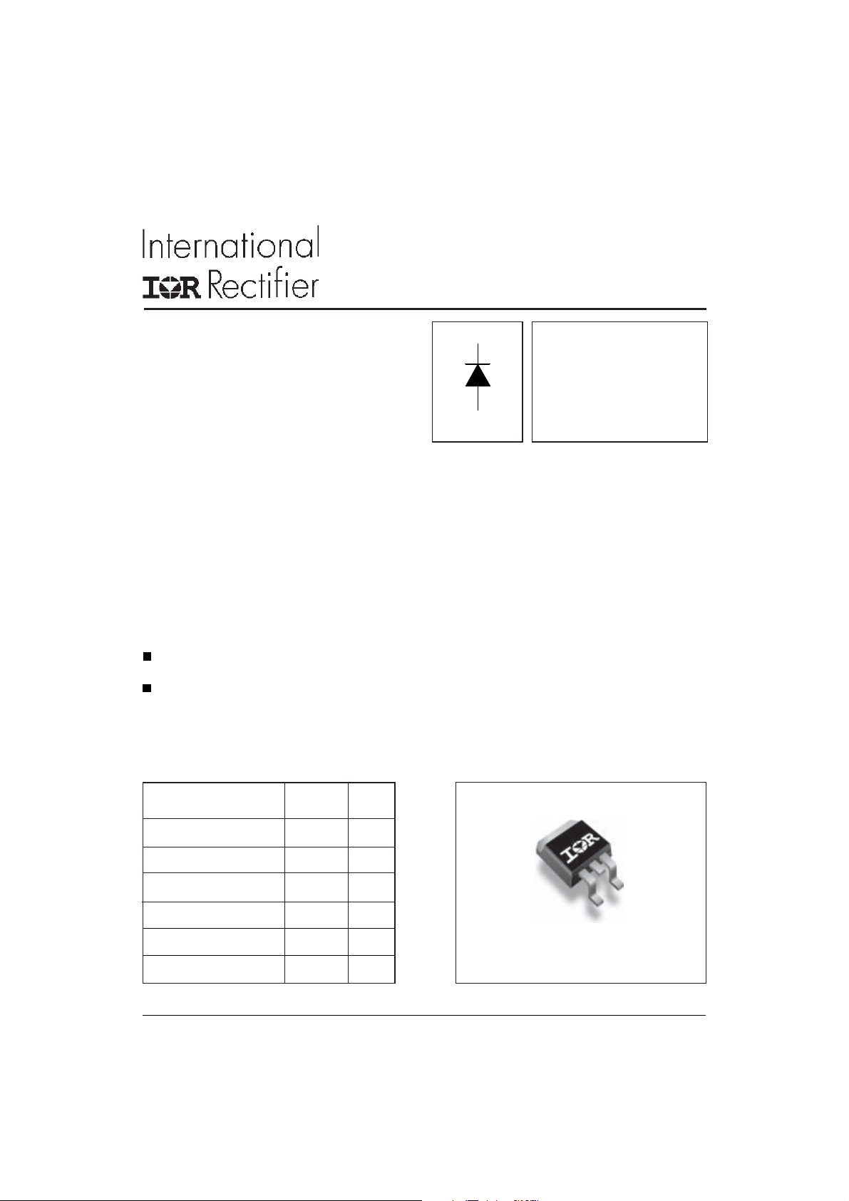
RECTIFIER DIODE
Lead-Free ("PbF" suffix)
Description/ Features
The 10ETF12SPbF fast soft recovery QUIETIR
rectifier series has been optimized for combined
short reverse recovery time and low forward
voltage drop.
The glass passivation ensures stable reliable
operation in the most severe temperature and
power cycling conditions.
Bulletin I2205 03/05
QUIETIR Series
10ETF12SPbF
VF< 1.33V @ 10A
t
= 80ns
rr
V
= 1200V
RRM
Typical applications are both:
output rectification and freewheeling in
inverters, choppers and converters
and input rectifications where severe
restrictions on conducted EMI should be met.
Major Ratings and Characteristics
Characteristics Values Units
I
Sinusoidal waveform 10 A
F(AV)
V
RRM
I
FSM
VF@ 10 A, TJ = 25°C 1.33 V
trr@ 1A, 100A/µs 80 ns
TJrange - 40 to 150 °C
1200 V
160 A
Package Outline
2
Pak (SMD-220)
D
10ETF12SPbF QUIETIR Series
Document Number: 94094
www.vishay.com
2
Bulletin I2205 03/05
Voltage Ratings
V
, maximum V
RRM
Part Number
peak reverse voltage peak reverse voltage 150°C
VVmA
10ETF12S 1200 1300 4
Absolute Maximum Ratings
Parameters 10ETF..S Units Conditions
I
Max. Average Forward Current 10 A @ TC = 125° C, 180° conduction half sine wave
F(AV)
I
Max. Peak One Cycle Non-Repetitive 160 10ms Sine pulse, rated V
FSM
Surge Current 185 10ms Sine pulse, no voltage reapplied
I2t Max. I2t for fusing 128 10ms Sine pulse, rated V
180 10ms Sine pulse, no voltage reapplied
I2√t Max. I2√t for fusing 1800 A2√s t = 0.1 to 10ms, no voltage reapplied
A
A2s
, maximum non repetitive I
RSM
applied
RRM
applied
RRM
RRM
Electrical Specifications
Parameters 10ETF..S Units Conditions
VFMMax. Forward Voltage Drop 1.33 V @ 10A, TJ = 25°C
rtForward slope resistance 22.9 m Ω TJ = 150°C
V
Threshold voltage 0.96 V
F(TO)
IRMMax. Reverse Leakage Current 0.1 TJ = 25 °C
4T
mA
= 150 °C
J
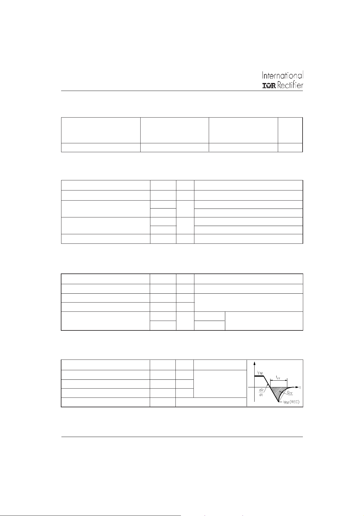
Recovery Characteristics
Parameters 10ETF..S Units Conditions
trrReverse Recovery Time 310 ns IF @ 10Apk
IrrReverse Recovery Current 4.7 A @ 25A/ µs
QrrReverse Recovery Charge 1.05 µC @ 25°C
S Typical Snap Factor 0.6
VR = rated V
RRM
10ETF12SPbF QUIETIR Series
Document Number: 94094
www.vishay.com
3
Thermal-Mechanical Specifications
Parameters 10ETF..S Units Conditions
TJMax. Junction Temperature Range - 40 to 150 °C
T
Max. Storage Temperature Range - 40 to 150 °C
stg
R
Max. Thermal Resistance Junction 1.5 °C/W DC operation
thJC
to Case
R
Max. Thermal Resistance Junction 62 °C/W
thJA
to Ambient (PCB Mount)**
TsSoldering Temperature 240 °C
wt Approximate Weight 2 (0.07) g (oz.)
Case Style D2Pak (SMD-220)
Marking Device 10ETF12S
** When mounted on 1" square (650mm2) PCB of FR-4 or G-10 material 4 oz (140µm) copper 40°C/W
For recommended footprint and soldering techniques refer to application note #AN-994
Bulletin I2205 03/05
150
145
140
135
130
125
120
115
Maximum Allowable Case Temperature (°C)
024681012
Average Forward Current (A)
10ETF.. Series
R (DC) = 1.5 °C /W
thJC
Cond uction Ang le
30°
60°
90°
120°
180°
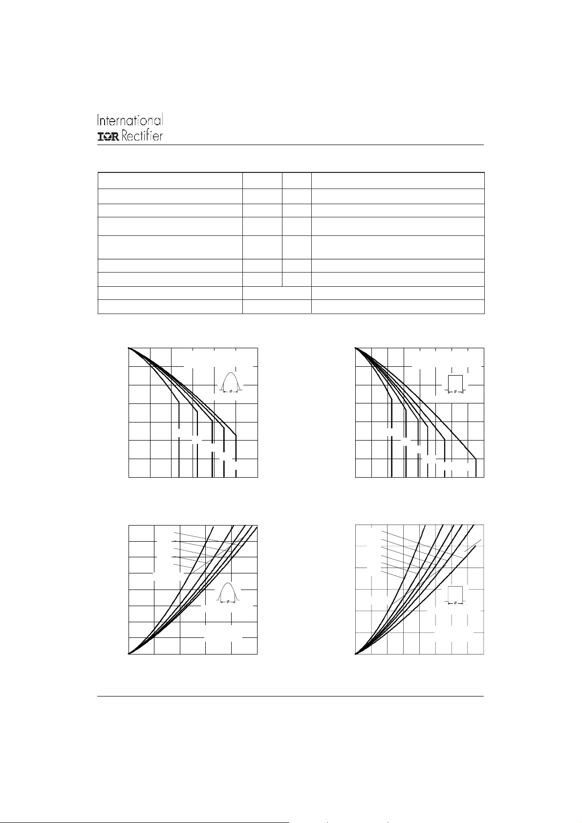
Fig. 1 - Current Rating Characteristics
16
14
12
10
8
6
4
2
0
Maximum Average Forward Power Loss (W)
0246810
180°
120°
90°
60°
30°
RM S Lim i t
Conduc tion Angle
10.TF.. Series
T = 150°C
J
Average Forward Current (A)
150
145
140
135
130
125
120
115
Maximum Allowable Case Temperature (°C)
0 2 4 6 8 10121416
Average Forward Current (A)
10ETF.. Serie s
R ( DC) = 1.5 °C /W
thJC
30°
60°
90°
Cond uction Period
120°
180°
Fig. 2 - Current Rating Characteristics
24
DC
180°
20
120°
90°
60°
16
30°
12
RM S Lim i t
8
4
0
Maximum Average Forward Power Loss (W)
0 2 4 6 8 10 12 14 16
Average Forward Current (A)
Conduction Period
10ETF.. Series
T = 150°C
J
Fig. 3 - Forward Power Loss Characteristics Fig. 4 - Forward Power Loss Characteristics
DC

10ETF12SPbF QUIETIR Series
Document Number: 94094
www.vishay.com
4
Bulletin I2205 03/05
180
At Any Rated Load Condition And With
Rated V Applied Following Surge.
160
140
RRM
Init ial T = 150°C
J
@ 60 Hz 0.0083 s
@ 50 Hz 0.0100 s
120
100
80
60
10ETF.. Series
Peak Half Sine Wave Forward Current (A)
40
110100
Num be r Of Equa l A mplit ud e Half Cyc le Curre nt Pulses (N)
Fig. 5 - Maximum Non-Repetitive Surge Current
1000
T = 2 5° C
J
100
10
200
Maximum Non Repetitive Surge Current
180
160
Versus Pulse Train Duration.
Initial T = 150°C
No Voltage Reapplied
Rated V Reapplied
RRM
140
120
100
80
60
10ETF.. Serie s
Peak Half Sine Wave Forward Current (A)
40
0.01 0.1 1
Pulse Train Duration (s)
Fig. 6 - Maximum Non-Repetitive Surge Current
T = 150°C
J
J
Instantaneous Forward Current (A)
1
0.5 1 1. 5 2 2.5 3 3.5 4 4.5
Instantaneous Forward Voltage (V)
Fig. 7 - Forward Voltage Drop Characteristics
0.6
0.5
0.4
0.3
I = 10 A
0.2
FM
0.1
Ma ximum Reve rse Rec ov e ry Time - Trr (µs)
0
0 4 0 80 120 160 200
Rat e Of Fall Of Forwa rd Current - d i/ d t (A/ µs)
10ETF.. Series
T = 25 °C
J
8 A
5 A
2 A
1 A
Fig. 8 - Recovery Time Characteristics, TJ = 25°C
10ETF.. Series
0.8
10ETF.. Seri es
T = 150 ° C
J
0.6
0.4
0.2
Ma ximum Reverse Rec ove ry Time - Trr (µs)
0
0 40 80 120 160 200
I = 10 A
FM
8 A
5 A
2 A
1 A
Ra te Of Fall Of Forward Current - di/d t (A/µs)
Fig. 9 - Recovery Time Characteristics, TJ = 150°C

10ETF12SPbF QUIETIR Series
Document Number: 94094
www.vishay.com
5
Bulletin I2205 03/05
2
1.6
1.2
10ETF.. Serie s
T = 2 5 ° C
J
I = 10 A
FM
8 A
5 A
0.8
2 A
0.4
0
0 40 80 120 160 200
Maximum Reverse Re covery Charge - Qrr (µC)
Rate Of Fall Of Forward Current - di/dt (A/µs)
1 A
Fig. 10 - Recovery Charge Characteristics, TJ = 25°C
20
10ETF.. Series
T = 2 5 ° C
16
12
8
4
J
I = 10 A
FM
8 A
5 A
2 A
1 A
5
10ETF.. Series
T = 150 °C
J
I = 10 A
FM
4
3
8 A
5 A
2
2 A
1
1 A
0
0 40 80 120 160 200
Maximum Reverse Recovery Charge - Qrr (µC)
Rate Of Fall Of Forward Current - di/dt (A/µs)
Fig. 11 - Recovery Charge Characteristics, TJ = 150°C
25
10ETF.. Se ries
T = 150 °C
20
15
10
5
J
I = 10 A
FM
8 A
5 A
2 A
1 A
0
Ma ximum Reve rse Rec ov ery Cu rre nt - Irr (A )
0 40 80 120 160 200
Rate Of Fall Of Forward Current - di/dt (A/µs)
0
Maxim um Reverse Recovery Curren t - Irr (A)
0 40 80 120 160 200
Rate Of Fall Of Forward Current - di/dt (A/µs)
Fig. 12 - Recovery Current Characteristics, TJ = 25°C Fig. 13 - Recovery Current Characteristics, TJ = 150°C
10
Steady State Value
(DC Opera tion)
thJC
1
D = 0.50
D = 0.33
D = 0.25
D = 0.17
D = 0.08
0.1
0.01
Single Pulse
Transient Thermal Impedance Z (°C/W)
0.001
0.001 0.0 1 0. 1 1 10
Square Wave Pulse Duration (s)
Fig. 14 - Thermal Impedance Z
thJC
10ETF.. Series
Characteristics

10ETF12SPbF QUIETIR Series
Document Number: 94094
www.vishay.com
6
Bulletin I2205 03/05
Outline Table
15.49 (0.61)
14.73 (0.58)
3X
93°
1.40 (0.055)
1.14 (0.045)
10.16 (0.40)
REF.
13
2
6.47 (0.25)
6.18 (0.24)
2.61 (0.10)
2.32 (0.09)
8.89 (0.35)
REF .
0.93 (0.37)
2X
0.69 (0.27)
4.57 (0.18)
4.32 (0.17)
0.61 (0.02) MAX.
5.08 (0.20) REF.
Dimensions in millimeters and inches
4.69 (0.18)
4.20 (0.16)
1.32 (0.05)
1.22 (0.05)
5.28 (0.21)
4.78 (0.19)
0.55 (0.02)
0.46 (0.02)
MINIMU M RECOMMENDE D FOOTPRINT
11.43 (0.45)
8.89 (0.35)
17.78 (0.70)
3.81 (0.15)
2.08 (0.08)
2X
2.54 (0.10)
2X
Marking Information
THIS IS A 10ETF12S WITH
LOT CODE 5K 3A
ASSEMBLED ON WW 12, 2000
INTERNATIONAL
RECTIFIER
LOGO
ASSEMBLY
LOT CODE
10ETF12S
PART NUMBER
DATE CODE
YEAR 0 = 2000
WEEK 12
P = LEAD-FREE

Tape & Reel Information
Document Number: 94094
www.vishay.com
7
TRR
FEED DIRECTION
TRL
FEED DIRECTION
13.50 ( 0.532)
12.80 ( 0.504)
1. 85 (0 .07 3)
1. 65 (0 .06 5)
DIA.
1.60 (0.063)
1.50 (0.059)
4.10 (0.161)
3.90 (0.153)
10.90 (0.429)
10.70 (0.421)
Dimensions in millimeters and inches
10ETF12SPbF QUIETIR Series
Bulletin I2205 03/05
1.60 (0.063)
1.50 (0.059)
11.6 0 ( 0.457 )
11.4 0 ( 0.449 )
1.75 (0.06 9)
1.25 (0.04 9)
16.10 (0.634)
15.90 (0.626)
26.40 (1.039)
24.40 (0.961)
DIA.
DIA.
15.4 2 (0. 609)
15.2 2 (0. 601)
0.36 8 (0. 014 5)
0.34 2 (0. 013 5)
24.30 (0.957)
23.90 (0.941)
4.72 (0.1 86)
4.52 (0.1 78)
360 (14.173)
DIA. MAX.
60 (2 .362 )
DIA. MIN.
SMD-220 Tape & Ree l
When ordering, indicate the part
number, part orientation, and the
quantity. Quantities are in multiples
of 800 pi ece s per r eel for bo th
TRL and TRR.

10ETF12SPbF QUIETIR Series
Document Number: 94094
www.vishay.com
8
Bulletin I2205 03/05
Ordering Information Table
Device Code
10 E T F 12 S TRL PbF
6
1
1 - Current Rating (10 = 10A)
2 - Circuit Configuration:
3 - Package:
4 - Type of Silicon:
5 - Voltage Rating (12 = 1200V)
6 - S = Surface Mountable
7 - y none = Tape
3
E = Single Diode
T = D2Pak (TO-220AC)
F = Fast Soft Recovery Rectifier
52 4
7
y TRR = Tape & Reel (Right Oriented)
y TRL = Tape & Reel (Left Oriented)
8 - y none = Standard Production
y PbF = Lead-Free
8
This product has been designed and qualified for Industrial Level and Lead-Free.
Data and specifications subject to change without notice.
Qualification Standards can be found on IR's Web site.
IR WORLD HEADQUARTERS: 233 Kansas St., El Segundo, California 90245, USA Tel: (310) 252-7105
TAC Fax: (310) 252-7309
03/05

Legal Disclaimer Notice
Vishay
Notice
The products described herein were acquired by Vishay Intertechnology, Inc., as part of its acquisition of
International Rectifier’s Power Control Systems (PCS) business, which closed in April 2007. Specifications of the
products displayed herein are pending review by Vishay and are subject to the terms and conditions shown below.
Specifications of the products displayed herein are subject to change without notice. Vishay Intertechnology, Inc., or
anyone on its behalf, assumes no responsibility or liability for any errors or inaccuracies.
Information contained herein is intended to provide a product description only. No license, express or implied, by
estoppel or otherwise, to any intellectual property rights is granted by this document. Except as provided in Vishay's
terms and conditions of sale for such products, Vishay assumes no liability whatsoever, and disclaims any express
or implied warranty, relating to sale and/or use of Vishay products including liability or warranties relating to fitness
for a particular purpose, merchantability, or infringement of any patent, copyright, or other intellectual property right.
The products shown herein are not designed for use in medical, life-saving, or life-sustaining applications.
Customers using or selling these products for use in such applications do so at their own risk and agree to fully
indemnify Vishay for any damages resulting from such improper use or sale.
International Rectifier
are registered trademarks of International Rectifier Corporation in the U.S. and other countries. All other product
names noted herein may be trademarks of their respective owners.
®
, IR®, the IR logo, HEXFET®, HEXSense®, HEXDIP®, DOL®, INTERO®, and POWIRTRAIN
®
Document Number: 99901 www.vishay.com
Revision: 12-Mar-07 1
 Loading...