

Bulletin I2028 rev. D 01/05
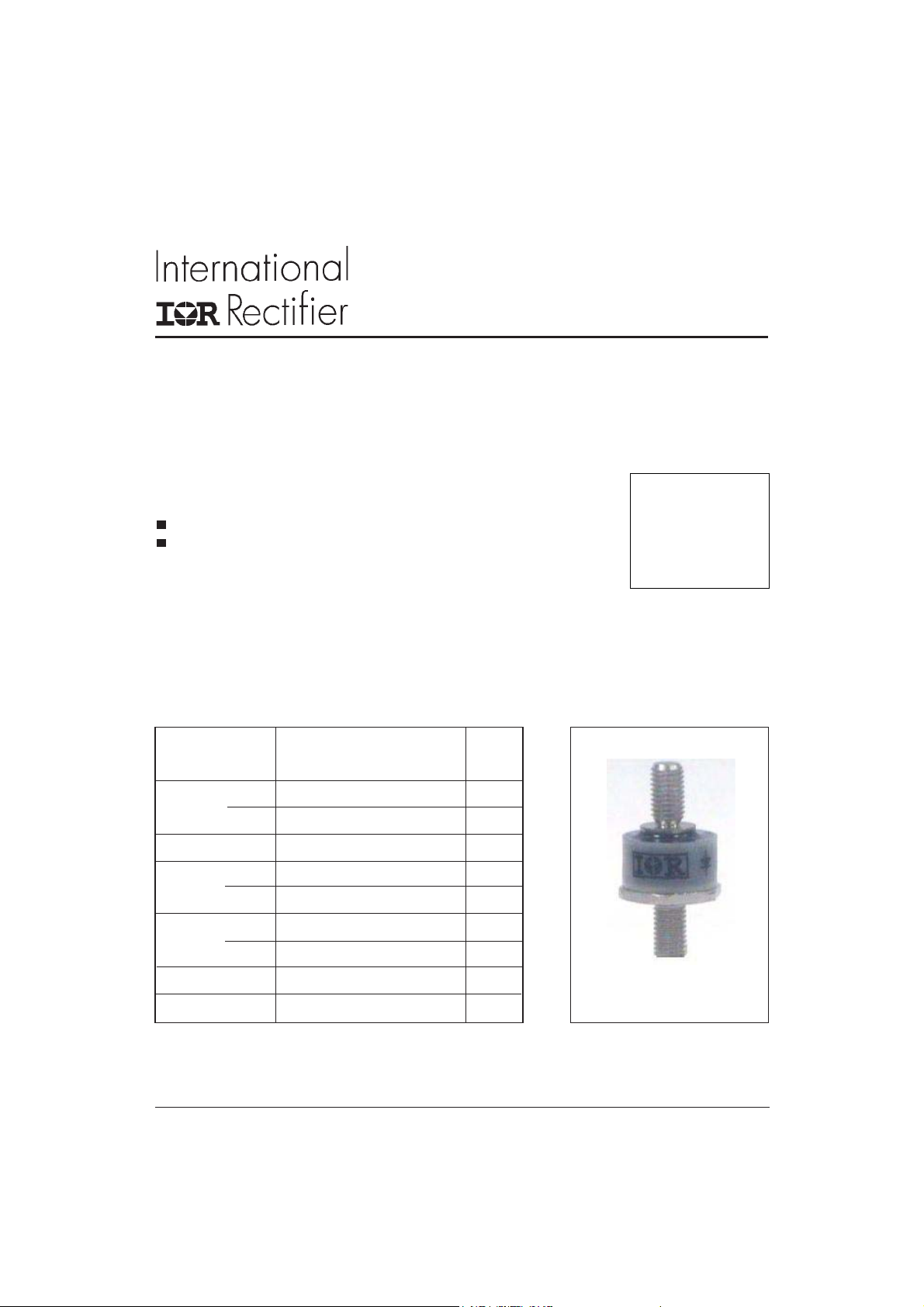
105PF40T
STANDARD RECOVERY DIODES
(Lead-Free)
Features
High surge current capability
Very low V
F
Major Ratings and Characteristics
Parameters 105PF Units
I
F(AV)
I
F(RMS)
I
FSM
@ T
C
@ 50Hz 2300 A
@ 60Hz 2400 A
105 A
150 °C
160 A
Stud Version
105 A
I2t@
V
RRM
T
J
50Hz 23900 A2s
@ 60Hz 26450 A2s
range 400 V
range - 40 to 1 80 °C
www.irf.com
case style
DO-203AB (DO-5)
1
105PF40T
Final I2028 rev. D 01/05
ELECTRICAL SPECIFICATIONS
Voltage Ratings
Voltage V
Type number Code repetitive peak repetitive peak @ T
105PF 40 400 500 5
, maximum V
RRM
, maximum non- I
RSM
reverse voltage reverse voltage
VVmA
Forward Conduction
Parameter 105PF Units Conditions
I
Max. average forward current 105 A 180° conduction, half sine wave
F(AV)
@ Case temperature 150 °C
150 A
135 °C
I
Max. RMS forward current 160 A
F(RMS)
I
Max. peak, one-cycle forward, 2300 t = 10ms No voltage
FSM
non-repetitive surge current 2400 t = 8.3ms reapplied
1970 t = 10ms 100% V
2050 t = 8.3ms reapplied Sinusoidal half wave,
2
t Maximum I2t for fusing 26450 t = 10ms No voltage Initial TJ = TJ max.
I
23900 t = 8.3ms reapplied
19400 t = 10ms 100% V
17440 t = 8.3ms reapplied
2
I
√t Maximum I2√t for fusing 200 kA2√s t = 0.1 to 10ms, no voltage reapplied
V
Value of threshold
F(TO)
voltage
Value of forward slope
r
f
resistance
V
Max. forward voltage drop 1.05 V VIpk= 200A, TJ = 25°C, tp = 400µs rectangular wave
FM
0.75 V TJ = TJ max.
1.0 m Ω TJ = TJ max.
A
RRM
A2s
RRM
RRM
= 150°C
J
max.
Thermal and Mechanical Specifications
Parameter 105PF Units Conditions
TJMax. junction operating temperature range -40 to 180
Max. storage temperature range -40 to 180
T
stg
Max. thermal resistance, junction to case 0.25 AC operation
R
thJC
R
Max. thermal resistance, case Mounting surface, smooth, flat and
thCS
to heatsink greased
0.25
T Allowable mounting torque 2.8 Nm Top thread; using bus-bar or plate, only.
25 lbf
(1) As general recommendation we
suggest to tight on hexagon and not on nut
3.4
+0-10%
30 lbf
+0-10%
(2) Torque must be appliable only to hexagon
and not to plastic structure
2.3
20 lbf
wt Approximate weight 17 (0.6) g (oz) unleaded device
Case style DO-203AB (DO5) See Outline Table
2
°C
°C/W
· in Avoid silicone grease on thread
Nm Bottom base; tighting on nut (1)
· in Not lubricated threads
N m Bottom base; tighting on hexagon (2)
· in Lubricated threads
www.irf.com

105PF40T
0
Bulletin I2028 rev. D 01/05
180
160
140
30˚
Maximum Allowable Case Temperature (°C)
120
0 20 40 60 80 100 120 140 160
Average Forward Current (A)
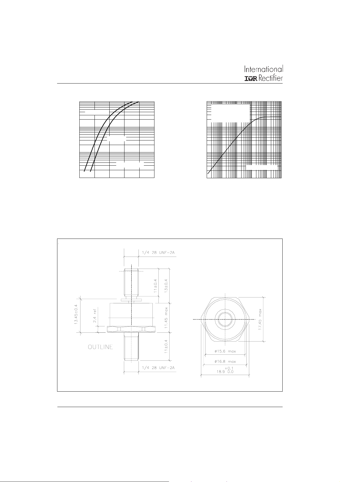
Fig. 1 - Current Ratings Characteristics Fig. 2 - Current Ratings Characteristics
180
160
140
120
180˚
120˚
90˚
60˚
30˚
105PF Series
Conduction Angle
60˚
90˚
100
RMS Limit
80
60
40
20
Maximum Allowable Case Temperature (°C)
0
0 40 80 120 160
Average Forward Current (A)
Fig. 3 - Current Ratings Characteristics
Conduction Angle
150PF Series
120˚
180˚
180
105PF Series
170
160
150
140
130
30˚
60˚
120
110
Maximum Allowable Case Temperature (°C)
100
0 50 100 150 200 250
Average Forward Current (A)
250
200
150
100
DC
180˚
120˚
90˚
60˚
30˚
RMS Limit
50
Maximum Allowable Case Temperature (°C)
0
0 50 100 150 200 250
Average Forward Current (A)
Fig. 4 - Current Ratings Characteristics
Conduction Period
90˚
120˚
180˚
Conduction Period
105PF Series
DC
2200
At Any Rated Load Condition And With
2000
Rated Vrrm Applied Following Surge.
1800
1600
1400
1200
1000
800
105PF Series
600
Peak Half Sine Wave Forward Current (A)
400
11010
Number Of Equal Amplitude Half Cycle Current Pulses (N)
Fig. 5 - Maximum Non-Repetitive Surge Current
www.irf.com
Initial Tj = Tj Max.
@ 60 Hz 0.0083 s
@ 50 Hz 0.0100 s
2500
Maximum Non Repetitive Surge Current
2000
Versus Pulse Train Duration.
Initial Tj = Tj Max.
No Voltage Reapplied
Rated Vrrm Reapplied
1500
1000
500
Peak Half Sine Wave Forward Current (A)
105PF Series
0
0.01 0.1 1 10
Fig. 6 - Maximum Non-Repetitive Surge Current
Pulse Train Duration (s)
3
105PF40T
Final I2028 rev. D 01/05
1000
Tj = Tj Max.
100
10
Instantaneous Forward Current (A)
1
0.6 0.8 1 1.2 1.4 1.6
Instantaneous Forward Voltage (V)
Fig. 7 - Forward Voltage Drop Characteristics
Outline Table
Tj = 25˚C
105PF Series
1
Steady State Value
RthJC = 0.25 K/W
(K/W)
thJC
(DC Operation)
0.1
0.01
Transient Impedance Z
0.001
0.0001 0.001 0.01 0.1 1 10
Square Wave Pulse Duration (s)
Fig. 8 - Thermal Impedance Z
Case Style DO-203AB (DO-5)
All dimensions in millimeters (inches)
85HF(R) Series
thJC
105PF
Characteristics
4
www.irf.com
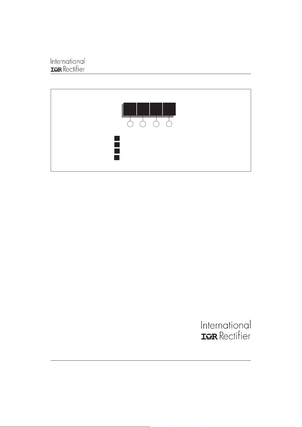
Ordering Information Table
105PF40T
Bulletin I2028 rev. D 01/05
Device Code
105 PF 40 T
24
1
1 - Current Rating (105 = 105A)
2 - PF = Plastic Package
3 - Voltage Rating (40 = 400V)
4 - T = Top Thread
3
This product has been designed and qualified for Industrial Level and Lead-Free.
Data and specifications subject to change without notice.
Qualification Standards can be found on IR's Web site.
IR WORLD HEADQUARTERS: 233 Kansas St., El Segundo, California 90245, USA Tel: (310) 252-7105
TAC Fax: (310) 252-7309
Visit us at www.irf.com for sales contact information. 01/05
www.irf.com
5
 Loading...