

ViscoTec Preeflow eco-DUO600 Commissioning And Maintenance Instructions

Dosiersystem
Commissioning and
Maintenance Instructions
eco-DUO600


eco-DUO600
Commissioning and Maintenance Manual
Table of contents
1 This manual 4
2 The dispenser 4
3 Safety 4
4 Starting up for the first time 5
4.1 Connecting the dosing units to the drive units 5
4.2 Connecting sensors for monitoring dosing pressure 6
4.3 Supplying and bleeding the medium. 7
4.4 Calibration 8
4.5 Recommendations for problem-free operation 9
4.6 Cleaning the outlets 10
5 Cleaning 11
5.1 Preparation 11
5.1.1 Separating the dispensers 11
5.1.2 Dismantling the dispenser 14
5.2 Assembly 16
6 Spare parts 18
7 Servicing 20
7.1 Changing the stator 20
7.2 Troubleshooting 20
8 Technical specifications 21
9 Disposal 22
Copyright © Version 1.4 3 / 23
1 This manual
Dear customer,
This manual forms part of the operating and maintenance manual for the dosing system
eco-CONTROL DUO. The operating and maintenance manual must have been read and
understood in full before commissioning or carrying out maintenance work on the ecoDUO 600.
2 The dispenser
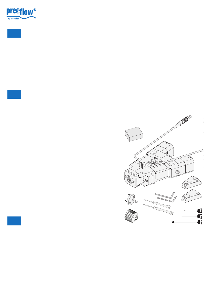
The dispenser is supplied with these components and accessories:
• eco-DUO 600
• 2 Stators
• 2 drive units (without Fig.)
• Assembly aid
• 2 screwdrivers
• 2 Allen wrenches
• Calibration adapter
• Attachment plates (2 x)
• Mixer set (3 static mixers)
• Commissioning and maintenance manual
Commissioning and Maintenance Manual
eco-DUO600
3 Safety
All instructions in the Safety section of the
maintenance and operating manual for the
dosing system must be complied with and implemented.
4 / 23 Version 1.4 Copyright ©
Fig. 1

eco-DUO600
Commissioning and Maintenance Manual
4 Starting up for the first time
Assembly Stators as follows:
• Disassembly dispensing unit as follows:
- 5.1.1, Separating the dispensers
- 5.1.2, Dismantling the dispenser
• Assembley Stators, see 5.2, Assembly
Do not switch on 2K dispenser until medium has been delivered to it. Otherwise there is
a risk of damage to the equipment. Even a brief period of dry running can lead to the
stator being destroyed.
4.1 Connecting the dosing units to the drive units
• Turn the set screws (21) in the thread such that they do not protrude into the coupling
area. Danger of damage to the fit.
• Attach the star-shaped couplings (22) onto the coupling of the drive units (A).
• Couple the drive units (A) to the dosing units until a gap of <1mm is achieved between
the anti-rotation lock (23) and the dosing units.
• Position the anti-rotation lock correctly by turning the dosing units.
• Bring the drive units and dosing units together completely.
23
21
A
21
Fig. 2
Copyright © Version 1.4 5 / 23
22

Commissioning and Maintenance Manual
4.2 Connecting sensors for monitoring dosing pressure
Attention:
The sensor cables must not be drilled during assembly!
Connect both sensors to the flowscreen analysis system*
* According to the instructions provided.
eco-DUO600
6 / 23 Version 1.4 Copyright ©
eco-DUO600
Commissioning and Maintenance Manual
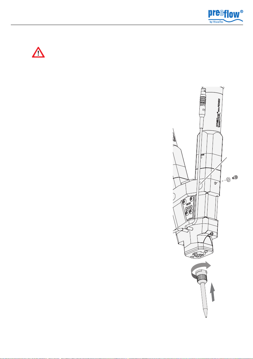
4.3 Supplying and bleeding the medium.
Follow the safety stipulations and instructions of the manufacturer of the medium
to be used to fill the unit. If applicable, use the required protective equipment. If
the medium is being conveyed for the first time, there is a danger from medium
spurting out. Air bubbles can cause uncontrollable spurting out. Ensure that you stand
back a safe distance.
• Connect the tank (supply line, cartridge) of the media to
both dispenser medium inputs (B).
(See section 8, Technical specifications, page 21 for
details of the thread)
• Bring the eco-DUO 600 into vertical position.
• Position the static mixing pipe (24) and lock in place.
For each dispenser:
• Connect the eco-DUO 600 to the power supply and
convey the medium until it comes out of the static mixing
pipe free from bubbles*.
Tip: Connecting a hose to the mixing pipe can protect the
eco-DUO 600 from being wetted with the medium.
B
27
28
• Unscrew the air bleed screw (27) with washer (28) to
bleed. Wipe off leaking medium with a cloth.
Tip: Never use the same cloth for both mediums. It would
cause a reaction between the components.
• Tighten the air bleed screw again.
* When filling for the first time, the blocking medium is first
removed from inside the dispenser (stator).
24
Fig. 3
Copyright © Version 1.4 7 / 23
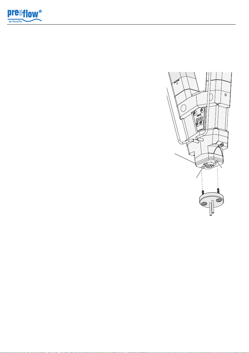
4.4 Calibration
A calibration adapter is available for calibrating the eco-DUO 600. It is mounted on the
outlets. The eco-Control EC 200-DUO calibration programmes can be used to determine
the exact dosing quantities and save them for the calculation in the dosing programmes.
Calibrating the dispenser
• Remove the static mixing pipe.
• Unscrew the screws (9) in the locking plate (11).
• Mount the calibration adapter (35)
• Carry out the calibration in accordance with the ecoControl EC 200-DUO operating manual.
Commissioning and Maintenance Manual
eco-DUO600
11
Once calibration is complete, fasten the locking plate and
position the static mixing pipe.
9
9
35
Fig. 4
8 / 23 Version 1.4 Copyright ©
 Loading...