


Operating and
maintenance
instructions
eco-CONTROL
EC200 DUO
Dosing system
Translation of the German original operating manual

Item number 20202 print 21.2.12

Dosing system eco-CONTROL EC200 DUO
Operating and maintenance instructions
Contents
1 Introduction 5
2 Features 6
3 Scope of supply 6
3.1 Mixer set - - - - - - - - - - - - - - - - - - - - - - - - - - - - - - - 6
4 Safety 7
4.1 Informal safety measures - - - - - - - - - - - - - - - - - - - - - - - 7
4.2 Use of symbols - - - - - - - - - - - - - - - - - - - - - - - - - - - - 7
4.3 Correct use, warranty - - - - - - - - - - - - - - - - - - - - - - - - - 7
4.4 Qualifications of the operators and maintenance personnel - - - - - - 8
4.5 Organisational measures - - - - - - - - - - - - - - - - - - - - - - - 8
4.6 Preparation for commissioning - visual inspection - - - - - - - - - - - 8
4.7 Preventing material damage to the motors of the 2K-dispenser - - - - 8
4.8 Sources of danger due to Dosing system - - - - - - - - - - - - - - - 9
5 Operation 10
5.1 Displays and controls - - - - - - - - - - - - - - - - - - - - - - - - - 10
5.2 Connections - - - - - - - - - - - - - - - - - - - - - - - - - - - - - 11
5.3 Symbols on the screen - - - - - - - - - - - - - - - - - - - - - - - - 12
5.4 Functional and operational schematic - - - - - - - - - - - - - - - - - 13
5.5 Starting up for the first time - - - - - - - - - - - - - - - - - - - - - - 14
5.5.1 Save the calibration values of the dosing pressure sensors 14
5.6 Starting up - - - - - - - - - - - - - - - - - - - - - - - - - - - - - - 15
5.6.1 Important settings 15
5.7 Shutting down - - - - - - - - - - - - - - - - - - - - - - - - - - - - 15
5.8 The dosing programs and their areas of application - - - - - - - - - - 15
5.8.1 Dosing programs 16
5.8.2 Operating modes 16
5.9 Calibrating - - - - - - - - - - - - - - - - - - - - - - - - - - - - - - 17
5.9.1 Automatic calibration 17
5.9.2 Calibration manual 18
Copyright © Version 1.4 3 / 43

Dosing system eco-CONTROL EC200 DUO
5.10 Settings - - - - - - - - - - - - - - - - - - - - - - - - - - - - - - - 19
5.10.1 Mixing ratio 19
5.10.2 Mixer size 19
5.10.3 Setting the pot life, flush the mixer 19
5.10.4 Dosing quantity 20
5.10.5 Dosing time 20
5.10.6 Flow rate 20
5.10.9 Dosing pressure monitor 21
5.10.7 Sucking back 21
5.10.8 Dosing time 21
5.10.10 Tolerance value primary pressure monitoring 22
5.10.11 Password protection 22
5.10.12 Analogue Input 25
5.10.14 System and error messages 26
5.10.13 Time and date 26
5.11 Creating dosing programs - - - - - - - - - - - - - - - - - - - - - - - 27
5.12 Selecting the dosing program - - - - - - - - - - - - - - - - - - - - - 27
5.13 Copying the dosing program - - - - - - - - - - - - - - - - - - - - - 28
5.14 Changing a dosing program - - - - - - - - - - - - - - - - - - - - - - 29
5.15 Dosing, selected directly without dosing program - - - - - - - - - - - 30
5.16 Dosing, using a dosing program - - - - - - - - - - - - - - - - - - - - 31
5.17 Monitoring / displaying dosing pressure - - - - - - - - - - - - - - - - 31
5.18 Manual flush - - - - - - - - - - - - - - - - - - - - - - - - - - - - - 31
5.19 Bleeding the 2K-dispenser after filling / refilling it and after cleaning - - 32
5.20 Error messages - - - - - - - - - - - - - - - - - - - - - - - - - - - - 32
5.21 Clearing error messages - - - - - - - - - - - - - - - - - - - - - - - 32
5.22 Error message dosing pressure monitor error - - - - - - - - - - - - - 32
5.23 Service - - - - - - - - - - - - - - - - - - - - - - - - - - - - - - - - 33
5.23.1 Operating information 33
5.23.2 Formatting the memory card 33
Operating and maintenance instructions
6 Accessories / spare parts 33
7 Troubleshooting / Maintenance 34
8 Technical data 35
8.1 Dosing control - - - - - - - - - - - - - - - - - - - - - - - - - - - - 35
8.2 Dispenser - - - - - - - - - - - - - - - - - - - - - - - - - - - - - - 35
8.3 Interface description - - - - - - - - - - - - - - - - - - - - - - - - - 36
8.3.1 System plugs 36
8.3.2 Logical links of the outputs 38
9 Disposal 42
10 EC-Declaration of Conformity 43
4 / 43 Version 1.4 Copyright ©

Dosing system eco-CONTROL EC200 DUO
Operating and maintenance instructions
1 Introduction
Dear customer,
we congratulate you on buying your Dosing system. We are certain that it will fully meet
your requirements. We wish you trouble-free and successful operation.
The dosing system eco-CONTROL EC200-K is made up of the dosing control and the
2K dispensers.
The Dosing system has been designed and tested for the most precise work with our
dispensers. The Dosing system has a wide variety of setting options for the dosing
quantity and time. All the values that are related to production can be saved and changed
at any time. Operation is done via an intuitive operator guidance system using a graphic
user interface. It is possible to operate two dispensers at the same time. It is possible to
set it up for other dispensers at any time without noteworthy setting-up times.
The dispensers have been developed and tested for high-precision work with products
ranging from low to high viscosity with extremely high repeat precision.
They are rotating displacement systems consisting of a rotor and stator and can be
dismantled in no time. A number of voids are produced as a result of the various
geometries of the conveying elements. Turning the rotor in the stator creates conveyance
which is either proportional to the angle of rotation or rpm-dependent.
Since the direction of flow is reversible, the medium can be sucked back to allow a clean
break of the thread. Self-sealing depends on the viscosity.
We would be glad of your help as part of our efforts to maintain our standard of quality at
the highest possible level. Please tell us about any possible ways we can improve our
product.
Copyright © Version 1.4 5 / 43

2 Features
Small
Medium
Large
Functions in brief with your transactions in the document:
Feature Section Page
3 dosing programs: Quantity Start/stop Time program 5.8.1 16
24 different dosing programs (operation with memory card) 5.11 27
Sucking back of the medium to prevent dripping 5.10.7 21
Adjustable pot life, automatic mixer filling 5.10.3 19
Adjustable flushflush time, prevents the medium from hardening in the
mixer
Flow quantity per minute can be set 5.10.6 20
Calibration of the controller / 2K- dispenser for exact working 5.9 17
Connection for foot switch and / or external signal 5.2 11
Pressure monitoring at the medium supply with primary pressure 5.10.10 22
Dosing pressure monitor 5.10.9 21
Level monitoring for supply tank / cartridge / tank 8.3 36
Overcurrent monitoring of the connected dispenser to protect against
damage due to sticking medium, for example.
Visualisation of the operating states via coloured displays 5.4 13
Dosing system eco-CONTROL EC200 DUO
Operating and maintenance instructions
5.10.3 19
5.10.14 26
3 Scope of supply
Dosing system eco-CONTROL EC200 DUO (delivery as a set with 2K-dispenser)
- 2K dispenser
- Calibration adapter for 2Kdispenser
- Mixer set
- Mains adapter with cable
- SD memory card
- Operating and maintenance
instructions
- 2 pressure sensors with
installation wrench
- Sticker set for marking
components
3.1 Mixer set
The mixer set contains three different mixers in the sizes: Small, medium and large.
(Fig. in original size)
6 / 43 Version 1.4 Copyright ©
Dosing system eco-CONTROL EC200 DUO
Operating and maintenance instructions
4 Safety
4.1 Informal safety measures
- The operating and maintenance manual must be kept, together with the operating and
maintenance manual of the dispenser(s), at the site where the dosing system is used
at all times.
- General and local regulations on health, safety and environmental protection must also
be provided and complied with.
4.2 Use of symbols
The following symbols are used in these instructions:
Text in
italics
•
-List
1. Numbered listing of a work flow sequence
1 Legend number in an illustration
Names of keys/buttons, connectors, chapters, screen displays, proper
names and input boxes
Listing of the work flow sequence
Warning note. Failure to observe these notes may result in injury and
damage to the Dosing system.
Reference to technical information about operation and / or about
preventing damage.
4.3 Correct use, warranty
The Dosing system is designed for controlling our dispensers in non explosion-protected
environments.
Any
- modifications and additions,
- use of non-genuine spare parts,
- repairs by persons or organisations not authorised by the manufacturer
- use without original sensors for monitoring dosing pressure
that are done without the explicit and written approval of the manufacturer, can lead to
the warranty being rendered null and void.
The manufacturer shall have no liability whatsoever for damage resulting from failure to
follow the Operating and maintenance instructions.
The chemical resistance of the parts which come into contact with the product (see the
commissioning and maintenance manual of the dispenser) must be ensured prior to
commissioning.
Copyright © Version 1.4 7 / 43

Dosing system eco-CONTROL EC200 DUO
Operating and maintenance instructions
4.4 Qualifications of the operators and maintenance personnel
The operating organisation is responsible for ensuring that the operators and
maintenance personnel are suitably qualified. The Operating and maintenance
instructions must have been read and understood. The relevant technical rules and safety
regulations must be complied with.
4.5 Organisational measures
The necessary personal protective equipment must be
provided by the operating organisation. All safety devices
that are fitted must be checked regularly. Safety glasses
and overalls must be worn during operation and cleaning
to provide protection against any splashes of chemicals.
All of the safety information contained in the respective
Operating and maintenance instructions for the dispenser(s) that are connected to the
Dosing system must be complied with.
4.6 Preparation for commissioning - visual inspection
The Dosing system must be visually examined each day before the start of work and
before all shift changes. If there is any doubt as to the system's readiness for operation,
it must be shut down immediately and inspected by a specialist before operation
resumes.
4.7 Preventing material damage to the motors of the 2K-dispenser
The 2K-dispenser lead (connector 16, Chapter 5.2, Connections, on page 11)
may only be connected and disconnected when the power supply is isolated.
The electronics in the drive motor could be damaged if this precaution is not
taken.
The 2K-dispenser should only be operated with the original pressure sensors
connected, which have been adapted to the controller.
8 / 43 Version 1.4 Copyright ©

Dosing system eco-CONTROL EC200 DUO
Operating and maintenance instructions
4.8 Sources of danger due to Dosing system
Failure to follow the instructions given below can result in damage to the unit and
possible severe injury to persons in the vicinity.
- Very high dosing pressures can be produced, depending on the viscosity and the speed
of rotation, and this could result in unintended spurting out of the medium. Check the
flow quantity in relation to the dosing needle used (needle cross-section).
- When it is started up for the first time and after being refilled, air bubbles that are
included in the medium could cause an uncontrollable spurting out of the outlet nozzle.
Only start production operation once the Dosing system has been completely
bled.
- Wear suitable protective clothing if chemical, corrosive or dangerous products are
being used. Note and comply with the safety stipulations and the information from
the manufacturer. Ensure sufficient bleeding or extraction of air. Take special safety
precautions if working with dangerous media, for example, provide eye flushing
facilities if working with corrosive chemicals.
Copyright © Version 1.4 9 / 43
5 Operation
Before commissioning the Dosing system, the safety information in
Chapter 4, Safety, starting on page 7, must have been read and understood.
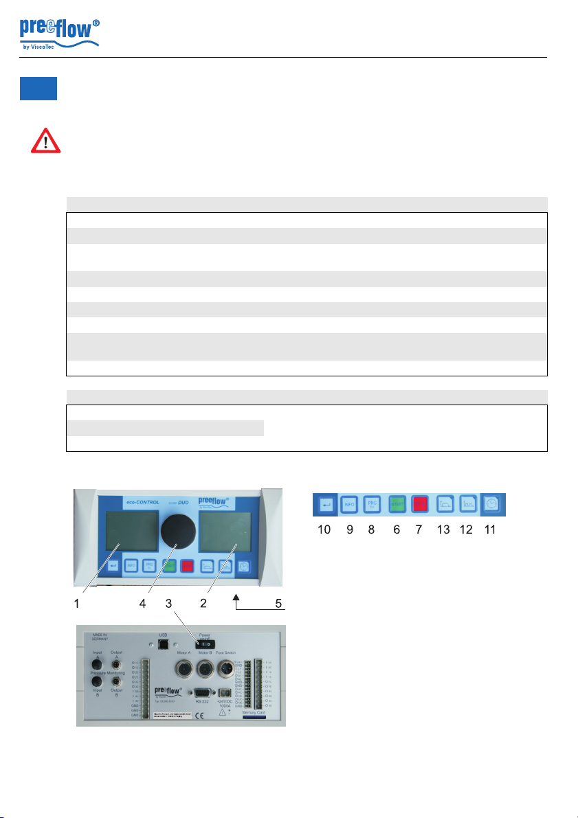
5.1 Displays and controls
Item Function, description
1+2 Graphic display
3 Mains switch
4 NAVI wheel Select and set variable values and input dialog
5 Key (without Fig., below) For service, software update.
6Key START Starts the dosing / function
7 Key STOP Stops the dosing / function; emergency stop
8Key PRG / Esc Selection of programming, quitting an input dialog.
9 Key INFO Brings further information onto the display, used to
10 Return Confirmation of a selection / value input.
Shortcut keys for dosing programs
11 Time program on the right, next to the key
12 Start / stop program
13 Quantity program
Dosing system eco-CONTROL EC200 DUO
Operating and maintenance instructions
confirmations.
quit page 2 in the dosing programs.
is a
status LED
10 / 43 Version 1.4 Copyright ©
Dosing system eco-CONTROL EC200 DUO
15 14
19
16 18
20
21
22
17
24
25
ViscoTecPumpenund Dosiertechnik GmbH
Amperstraße4 D-84513 Töging
AB
C1
C2
C
C3
C
B A
D
Operating and maintenance instructions
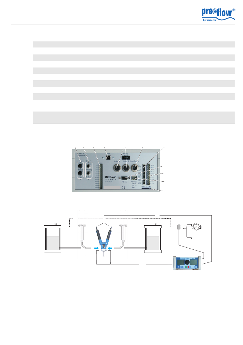
5.2 Connections
Item Function, description
14 + 15 System plugs *
16 Motor A / B
17 USB Data transfer with PC, interface
18 Foot switch Foot switch for hands-free operation
19 System plugs *
20 RS 232 Data transfer with PC, interface
21 +24 V/DC 100VA * Mains plug, connection for power supply
22 Memory Card Card reader for MMC/SD memory card
24 Primary pressure monitoring Pressure sensor connection for medium
25 Dosing pressure monitor Pressure sensor connection for medium
See section 8.3, page 36 for pin-outs
*
components A and B
components A and B
(The primary pressure does not apply for self-levelling liquids)
A Product supply A C2 Compressed air
B Product supply B C3 Dosing pressure monitor
C1 Primary pressure monitoring D Power supply dispenser
Copyright © Version 1.4 11 / 43
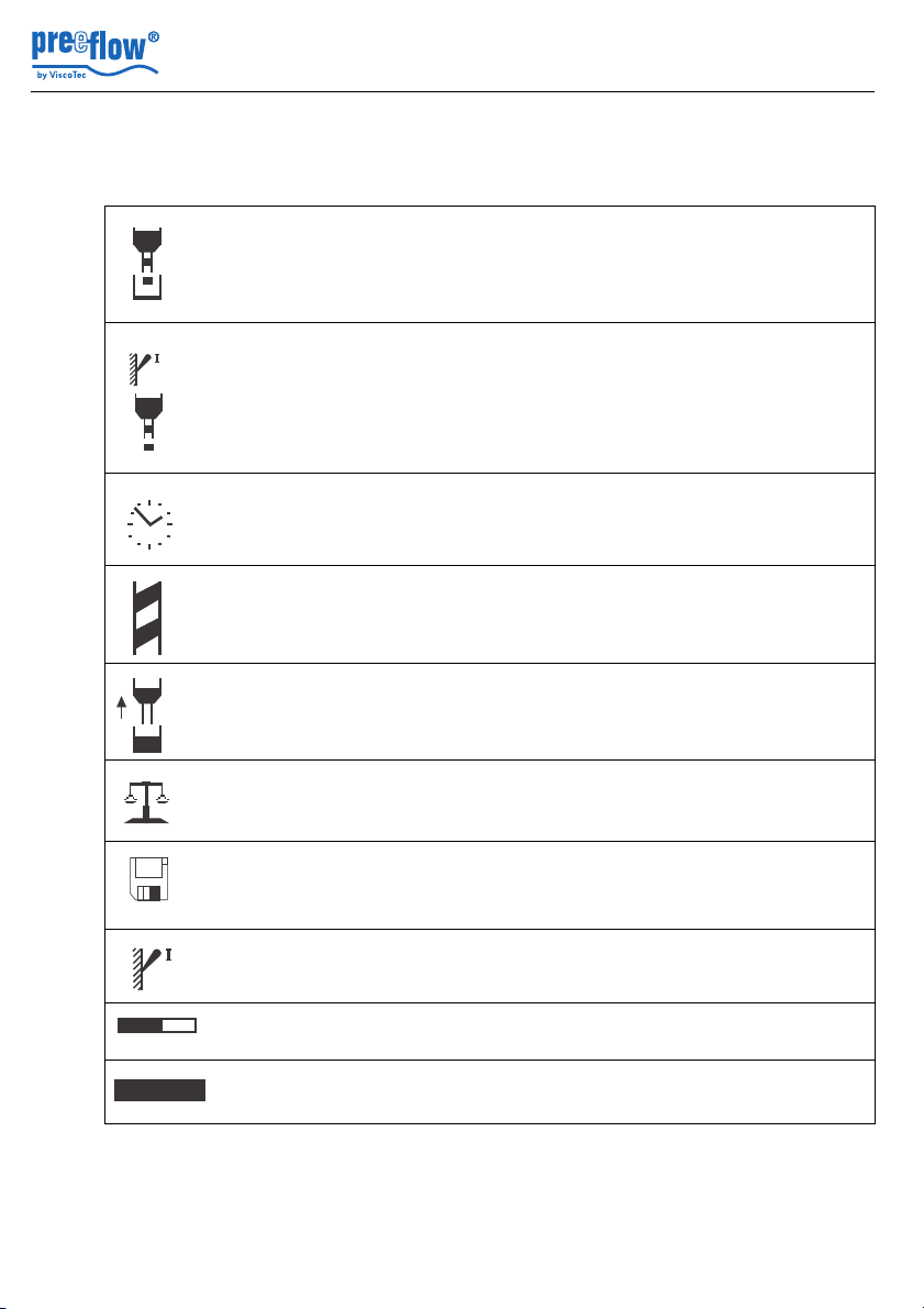
5.3 Symbols on the screen
O
O
0% 100%
Fault
Designation / function Description
Dosing system eco-CONTROL EC200 DUO
Operating and maintenance instructions
Dosing program
Quantity
Dosing program
Start / stop
Dosing program
Time
flow rate Dosing quantity per minute
See 5.8.1, Dosing programs, page 16
Quantity program
See 5.8.1, Dosing programs, page 16
Start / stop program
See 5.8.1, Dosing programs, page 16
Time program
1
.
Preventing dripping of the medium
Sucking back
The amount of medium that is "sucked back"
into the dispenser in connection with the
dosing process.
Calibrating
Matching the dispenser by determining the
effective flow rate.
Saving Used to save the last values that had been
amended. Only applies if a SD memory card
has been inserted.
Shows the current controlling of the dispenser
Start / stop
(high/low). The switch is set to I during dosing.
Relative quantity,
capacity
Dynamic display of the flow rate, for example
Plain text messages in the status line give
Fault
information on the relevant error message.
Details can be called up with the Info key.
1
In ml or g
12 / 43 Version 1.4 Copyright ©

Dosing system eco-CONTROL EC200 DUO
Press Start
Esc
Calibration auto
Motor A
ml
Desired qty
Actual qty
ml ml
00.500ml
00.000ml
A
B
00.500
Operating and maintenance instructions
5.4 Functional and operational schematic
The interaction of the screen displays, the input dialog and the function keys:
The control system has an intuitive input dialog. The
selection or the change of a value is offered on the screen to
suit the relevant program section. The corresponding area
(A) on the screen is then shown as inverse or framed.
The status bar (B) provides plain text messages in
accordance with the input dialogs.
NAVI wheel (See 5.1, Displays and controls, page 10)
Enables rapid selection, input and confirmation of different functions.
The rotation of the NAVI wheel switches to the next or previous selection, depending on
the direction of rotation, or changes a value.
A press of the NAVI wheel confirms a selection or a change in value that had just been
made. (Alternatively, the Return key can also be used for confirmation)
The illumination of the NAVI-wheel signalises the following operating states: Blue =
Ready for operation, Green = Dosing in progress, Red = Fault.
Changing a setting value
1. Select the value to be changed by rotating the NAVI wheel, the value is shown in
inverse.
2. Press the NAVI wheel, numbered items can be selected individually.
3. Select a numbered item by rotating the NAVI wheel, the numbered item flashes.
4. Press the NAVI wheel, the numbered item is shown in inverse.
5. Change the value by rotating the NAVI wheel and press the NAVI wheel for
confirmation, the numbered item flashes again. Another numbered item can be
selected.
6. If further numbered items are to be changed, start again from 3., and if not, continue.
7. Press the PRG key to confirm the change, the value that has just been set is shown
in inverse, if other values can be changed in the input dialog, these can now be
reached by rotating the NAVI wheel.
Esc
Used to quit an input dialog. In some cases it also assumes other functions. If that is the
case, this is shown in plain text in the status line.
Copyright © Version 1.4 13 / 43
Dosing system eco-CONTROL EC200 DUO
Calibration auto
Calibration manuell
Service
Flush manually A
Flush manually B
Administration
Programs
10 47h
Fr 18.03.11
Insert value
Esc
Calib. Outp. Press. A
Cal. factor
OK
output signal 094.7 mV
Operating and maintenance instructions
5.5 Starting up for the first time
Caution: The 2K-dispenser lead (connector 16, Chapter 5.2, Connections on page 11)
may only be connected and disconnected when the power supply is isolated. The
electronics in the drive motor could be damaged if this precaution is not taken.
• Operate the 2K-dispenser in accordance with the operating manual.
• Ensure that the mains switch has been turned off.
• Funktionsbereitschaft des 2K-Dispensers gemäß der mitgelieferten Inbetriebnahmeund Wartungsanleitung herstellen.
• Connect the plugs of the 2K-dispenser(s).
• Connect the plugs of both 2K-dispenser pressure sensors.
• Connect the power supply to the control system.
• Connect the mains plug of the mains adapter to the electrical mains.
• Turns on the mains switch.
5.5.1 Save the calibration values of the dosing pressure sensors
• Press PRG, system selection menu,
display 2 appears.
• Select Administration, display 25 appears.
• Select Calib. outp. pressure A , display 51 appears.
• Enter the calibration data supplied with the sensor
• Carry out the same setting with pressure sensor B.
Notice: The Dosing system is only ready for operation when the 2K-dispenser is
connected.
Tip: Use the stickers provided (letters A and B), to mark the following components.
14 / 43 Version 1.4 Copyright ©
- Both motors and dispensers and their plugs
- Pressure sensors and their plugs
- Supply lines for the media used
Display 2
Display 25
Display 51

Dosing system eco-CONTROL EC200 DUO
Operating and maintenance instructions
5.6 Starting up
• Turns on the mains switch.
• Position the new mixer where necessary. The dosing system set is ready for operation.
5.6.1 Important settings
Some important settings must be made to ensure problem-free operation of the 2Kdosing station. The following set-up makes the process easier:
- Mixer used
- Mixing ratio
- Pot life
- or flush time
- Pressure tolerance of the input pressure monitor, where used
5.7 Shutting down
The unit is shut down in reverse order of setting up.
5.8 The dosing programs and their areas of application
General
In order to achieve teh moste accurate results with the eco-CONTROL EC200 DUO, all
the main factors for a reproducible dosing operation can be set.
The dosing system must be recalibrated each time the medium is changed.
See 5.9, Calibrating page 17.
All the parameters of a dosing program can be saved. When using a memory card, 24
program slots are available for permanent storage.
Without the memory card, the data is stored temporarily on program slot 00. It is kept until
the dosing system is switched off.
The following values
can be defined,
depending on the
dosing program used:
Dosing program
Flow quantity
Flow rate
Dosing time
Sucked back quantity
Suck back speed
Pause before Sucking back
Material density
Quantity program x x x x x x
Start / stop program x x x x
Time program x x x x x
Copyright © Version 1.4 15 / 43

5.8.1 Dosing programs
Quantity program
Quantity program is used to give out a fixed and defined quantity of medium. Depending
on the 2K-dispenser and the medium used, it is possible to set very small amouts per
dosing. The dosing time is determined by the volume flow. The dosing operation can be
broken off at any time until the set time has expired (STOP key).
Start / stop program
The Start / stop program is used if the 2K-dispenser is set to convey the medium over an
individual period controlled by the operator (or external control). The output quantity can
be defined. The dosing quantity is determined by the volume flow.
Time program
The time program is used if the dosing is to be done for a set period. This is triggered by
the operator (or an external controller). The output quantity can be defined. The dosing
operation can be broken off at any time until the set time has expired (STOP key). The
maximum dosing time that can be set is 99.99 seconds.
5.8.2 Operating modes
Dosing manually
In the three dosing programs the dosing is initiated by pressing the START key. The
quantity program and the time program end the dosing by itself once the set values have
been reached or at the end of the set dosing time.
In the Start / stop program dosing can be ended by pressing the STOP key.
Dosing system eco-CONTROL EC200 DUO
Operating and maintenance instructions
Dosing with the foot switch
The dosing system reacts to the foot switch being activated as follows:
Dosing program Press the foot switch ... and release it again
Quantity program Quantity program ends
Start / stop program Dosing on Dosing off
Time program Time program ends
In the quantity and time programs the dosing can be stopped by pressing the STOP key
before the specified values have been reached (EMERGENCY STOP). A set pause and
a return flow are carried out as well.
16 / 43 Version 1.4 Copyright ©

Dosing system eco-CONTROL EC200 DUO
Calibration auto
Calibration manuell
Service
Flush manually A
Flush manually B
Administration
Programs
10 47h
Fr 18.03.11
Press Start
Esc
Calibration auto
Motor A
ml
Desired qty
Actual qty
ml ml
00.500ml
00.000ml
Operating and maintenance instructions
Dosing by means of an external controller
As in the case of dosing with the foot switch, but the triggering and termination of the
dosing are done by supplying an electrical signal. See 8.3, Interface description, page 36.
Notice: If a memory card is being used, press the foot switch briefly to load the saved and
most recently run program and to display it on the screen. Press the foot switch once
again to start the dosing. It behaves in exactly the same way with an external signal.
5.9 Calibrating
Preparation
• Mount the calibration adapter (see 2K-dispenser operating manual).
• Connect to the controller the 2K-dispenser that has been made ready for operation
and bled.
Caution: The 2K-dispenser lead (connector 16, Chapter 5.2, Connectionson page
11) may only be connected and disconnected when the power supply is isolated. The
electronics in the drive motor could be damaged if this precaution is not taken.
• Keep at hand a suitable vessel (calibration vessel) to catch and measure the quantity
required for calibration.
5.9.1 Automatic calibration
Notice: During the calibration operation the Dosing system cannot be operated by
either the foot switch or an external control signal.
• Press PRG, system selection menu,
display 2 appears.
• Select Calibration auto
• Select motor A or B, menu Calibration auto, display 15
appears.
Select whether the calibration is to be done with quantity
unit ml(µl) or g(mg)* and confirm this, the set quantity can
be set as desired.
• Set and confirm the set quantity.
The value preset in the Dosing system is to be regarded as the ideal value.
Copyright © Version 1.4 17 / 43
• Position the calibration vessel under the calibration adapter of the 2K-dispenser.
Display 2
Display 15

• Press the START key, the calibration starts, the 2K-dispenser is switched on and
Save with OK
Esc
Save calibration value
at prog. no.: 07
OK
Calibration auto
Calibration auto
Calibration manuell
Service
Flush manually A
Flush manually B
Administration
Programs
10 47h
Fr 18.03.11
Accept with OK
Esc
Calibration manual
OK
Degree of dosing qty
Adjustment range 90 ..110%
100.0 %
conveys the quantity specified by the system. This process can be repeated as often
as desired. e.g., for comparative measurements.
• The ACTUAL quantity that goes into the calibration vessel is determined in the
previously set measuring unit. See also 5.10.4, Dosing quantity.
• Input and confirm the ACTUAL quantity that has been determined.
• Select the OK button and confirm, the next dialog to save the calibration value
appears (display 17).
• Accept or discard the suggested program slot, confirm this,
and the system has been calibrated.
5.9.2 Calibration manual
The Calibration manual function provides a simplified option to recalibrate the system
without having to run through the entire process in the Calibration auto menu.
This can be helpful, for example, after changing the stator, in the event of batchrelated product variations, etc., whereby the set dosing value is not to be changed
(QA documents, etc.).
Caution: Setting the flow rate in the Calibration manual menu also changes the
dosing results of all the dosing programs by a linear factor.
Dosing system eco-CONTROL EC200 DUO
Operating and maintenance instructions
Display 17
• Press the PRG key, system selection menu, display 2
appears.
• Select Calibration manual.
• Select motor A or B, menu Calibration manual, display 40
appears.
• Confirm the flow rate and set the desired value with the
NAVI wheel
• Press the NAVI-wheel key, system selection menu, display
2 appears.
18 / 43 Version 1.4 Copyright ©
Display 2
Display 40

Dosing system eco-CONTROL EC200 DUO
Mixture
1.0:1.0
Mixer small
Pot time 00 : 23 : 45
Blank shot
Flush
Flushing Time
Flush A
Flush B
00:23:00
endless
G
Program n o. 07
Mixture
1.0:1.0
Mixer small
Pot time 00 : 23 : 45
Blank shot
Flush
Flushing Time
Flush A
Flush B
00:23:00
endless
G
Program n o. 07
Mixture
1.0:1.0
Mixer small
Pot time 00 : 23 : 45
Blank shot
Flush
Flushing Time
Flush A
Flush B
00:23:00
endless
G
Program n o. 07
Operating and maintenance instructions
5.10 Settings
5.10.1 Mixing ratio
If a dosing program is active, the mixing ratio is shown in
the right-hand display and can be changed. The value for
dispenser A can be set
(1:1 to 5:1).
See also 5.14, Changing a dosing program
Calculate the mixing ratio always by volume, not by weight.
5.10.2 Mixer size
If a dosing program is active, the mixer size is shown in the
right-hand display and can be changed.
The three sizes of the supplied mixer set are available for
selection: Small, medium and large.
See also 5.14, Changing a dosing program
The mixer size is taken into account in the flow quantity in
the Rinse mixer functions.
5.10.3 Setting the pot life, flush the mixer
The pot life is shown in display 26.3. It can be set in every
program (Chapter 5.14). It then starts running backwards on
every dosing. The remaining time is shown.
It is compulsory to enter the pot life.
Once the pot life has expired, dosing takes place (empty shot) in accordance with the
set mixer size, filling it with "fresh" medium.
Empty shot = single dosing
Continuous = ongoing in accordance with the pot life.
Display 26.3
Display 26.3
Display 26.3
The Rinse function can be activated after a pot life has been entered.
The value must be smaller than the pot life. It starts running backwards after the
mixer has been filled (while the pot life is running). The remaining time is shown.
Once the flush time has expired, the mixer is rinsed once with the component from
the selected dispenser (A or B). This ensures that the mixer is filled with just one
medium and protected against sticking. The quantity corresponds to the set mixer
size.
Copyright © Version 1.4 19 / 43

5.10.4 Dosing quantity
Time program
Esc
Time
0% 100%
ml/min
01.00 03.000 00.000
mlsec
SuckbackFlow rate
Flow rate
0% 100%
ml/min
03.000
General on determining the dosing amount.
Notice: If a value that differs from 100% is set in the Calibration manual menu
(section 5.9.2), this affects the results of the dosing.
The smallest dosing quantities can be determined most easily via the weight. We
recommend setting the material density first.
Dose your required quantity with the Start / stop program and weigh it. Now input in the
quantity program the quantity in g.
Setting the dosing amount as a value
1. Press the Quantity program shortcut key, display 3
appears.
2. Ensure that the required quantity unit* has been selected
in the Quantity display area.
3. Set and confirm the dosing amount.
5.10.5 Dosing time
1. Press the Time program shortcut key, display 10
appears.
2. Set, confirm and save the dosing time.
The set value remains active until the next change or until
the Dosing systems is switched off. Alternatively, a value of
its own for the flow rate can be assigned to each dosing
program (See 5.14, Changing a dosing program, page 29).
Dosing system eco-CONTROL EC200 DUO
Operating and maintenance instructions
Display 3
Display 10
5.10.6 Flow rate
The flow rate in quantity/min can be set in each dosing program. The
maximum flow rate that can be set is
6 ml/min, per dispenser (A and B). If a mix ratio of 1:1 is set, 12 ml/min is
conveyed.
• Selecting, changing and saving the displayed value.
The bar chart shows in what range (%) the flow rate is.
The set value remains active until the next change or until the Dosing systems is
switched off. Alternatively, a value of its own for the flow rate can be assigned to each
20 / 43 Version 1.4 Copyright ©
dosing program (See 5.14, Changing a dosing program, page 29).
Display 34

Dosing system eco-CONTROL EC200 DUO
Suckback
00.000
ml
Time program
Esc
Time
0% 100%
ml/min
01.00 03.000 00.000
mlsec
SuckbackFlow rate
Esc
Output
pressure
Max. press. A 20 Bar
20 Bar
Max. press. B
Operating and maintenance instructions
5.10.7 Sucking back
In order to effectively prevent any dripping of the medium, a value for the
sucking back can be set. For safety reasons, the sucking back is
restricted to a maximum quantity of 0.02ml.
• Selecting, changing and saving the displayed value.
The sucking back is done after each dosing operation.
The set value remains active until the next change or until the Dosing systems is
switched off. Alternatively, a value of its own for the sucking back can be assigned to
each dosing program (See 5.14, Changing a dosing program, page 29).
5.10.8 Dosing time
1. Press the Time program shortcut key, display 10
appears.
2. Set, confirm and save the dosing time.
The set value remains active until the next change or until
the Dosing systems is switched off.
Alternatively, a value of its own for the flow rate can be
assigned to each dosing program (See 5.14, Changing a
dosing program, page 29).
5.10.9 Dosing pressure monitor
The dosing pressure monitor protects the 2K-dispenser. If the mixer were blocked,
the pressure inside the dosing pumps could increase to a level where they could be
damaged.
Display 35
Display 10
In the dosing program currently opened (see also 5.14,
Changing a dosing program), the value for the dosing
pressure monitor can be entered in level 2 (display 26.1).
Copyright © Version 1.4 21 / 43
Display 26.1

Dosing system eco-CONTROL EC200 DUO
Calibration auto
Calibration manuell
Service
Flush manually A
Flush manually B
Administration
Programs
10 47h
Fr 18.03.11
Accept with OK
Esc
Tol. of input pressure
Tolerance
±
OK
0.3 Bar
Calibration auto
Calibration manuell
Service
Flush manually A
Flush manually B
Administration
Programs
10 47h
Fr 18.03.11
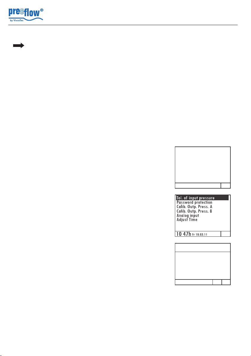
5.10.10 Tolerance value primary pressure monitoring
• Press PRG, system selection menu,
display 2 appears.
• Select Administration, display 25 appears.
• Select Inp. pressure tolerance, display 29 appears.
• In the pressure tolerance input dialog, enter the tolerance
and confirm with OK , display 25
appears.
Operating and maintenance instructions
Display 2
Display 25
Display 29
5.10.11 Password protection
The password protection blocks access to the settings of the controller and all
function keys. Dosing is possible via a foot switch (optional) and an external signal
(system plug). The most recently selected dosing program is always run and shown
on the display.
Setting range for the password: 0000 to 9999
Time of the automatic blocking after the last input: 30 seconds.
Turning on password protection
• Press the PRG key, system selection menu, display 2
appears.
• Select and confirm Administration, the Administration
menu, display 25 appears.
22 / 43 Version 1.4 Copyright ©
Display 2

Dosing system eco-CONTROL EC200 DUO
Calibration auto
Calibration manuell
Service
Flush manually A
Flush manually B
Administration
Programs
10 47h
Fr 18.03.11
Operating and maintenance instructions
• Select Password protection, display 41 appears.
• Press the Navi wheel, display On, changes to Off,
Protection active appears in the status bar.
• Select and confirm the password (code).
• Set the password by turning* the Navi wheel.
• Press the OK button and confirm, password protection has
been activated.
* Dynamic behaviour: The faster it is turned, the quicker the range of numbers
changes.
Note: If no further buttons are pressed, the password protection blocks the controller
after 30 seconds.
Releasing the controller
(if password protection has been activated)
Display 25
Display 41
The start screen is shown when it is in the blocked state.
Display 42 appears if a button is pressed.
• Select the correct password by turning the Navi wheel and
confirm it by pressing, then the start screen appears.
Note: If no further buttons are pressed, the password protection blocks the controller
after 30 seconds.
Turning off password protection
Release the controller as described above.
• Press the PRG key, system selection menu,
display 2 appears.
• Select and confirm Administration, the Administration
menu, display 25 appears.
Copyright © Version 1.4 23 / 43
Display 42
Display 2

Dosing system eco-CONTROL EC200 DUO
Operating and maintenance instructions
• Select Password protection, display 41 appears.
• Press the Navi wheel, display Off, changes to On,
Protection inactiveappears in the status bar.
• Press the OK button and confirm, password protection has
been deactivated.
Display 25
Display 41
24 / 43 Version 1.4 Copyright ©

Dosing system eco-CONTROL EC200 DUO
Technical connection data on the system connector (15)
Pin Analog signal Input resistance / resolution
A1 0-10V Ri = k 20 kΩ / 10 bit
A2 04-20mA Ri = 100Ω / 10Bit, maximum input voltage +5V
GND GND Analog
Calibration auto
Calibration manuell
Service
Flush manually A
Flush manually B
Administration
Programs
10 47h
Fr 18.03.11
Analog input
Off A1 A2
Analog activ A2
Esc OK
Operating and maintenance instructions
5.10.12 Analogue Input
Description: The flow rate (0-6 ml/min) for the connected pump(s) is regulated
proportional to the applied analog signal (V or mA).
This function is only effective in the Start / stop program.
Notice: Whatever the setting of the flow rate in the Start / Stop program, the
maximum flow rate of the pump (0-6 ml/min) must always be assumed. This setting
does not affect the return.
Switching the analogue input on / off
• Press the PRG key, system selection menu, display 2
appears.
• Select and confirm Administration, the Administration
menu, display 25 appears.
Display 2
• Select Analogue input, display 43 appears.
The current setting is shown in the status bar.
• Select the desired setting and press Navi wheel, the status
bar displays Press OK to accept.
• Select the OK button and confirm, the setting is activated.
Copyright © Version 1.4 25 / 43
Display 25
Display 43

Notice: If one of the two analogue inputs is active, this will
A2 activ
Start/stop
Esc
SuckbackFlow rate
0% 100%
00.000
ml
O
Start/ stop
Calibration auto
Calibration manuell
Service
Flush manually A
Flush manually B
Administration
Programs
10 47h
Fr 18.03.11
10 47h
Fr 18.03.11
Dosing System
eco-Control EC200 DUO
Config. alarm messages
Level control
Primary pr. control
Over-curent control
Volume OK
Volume alarm
10 47h
Fr 18.03.11
Off
Off
On
30
30
be indicated in plain text in the display of the Start / Stop
Program (display 44) instead of the dynamic flow rate
display.
5.10.13 Time and date
• Press PRG, system selection menu,
display 2 appears.
• Select Administration, display 25 appears.
• Select Set the time , the time and the
date can be set by field in the status bar using the NAVI-
wheel.
• Confirm the setting with PRG
Dosing system eco-CONTROL EC200 DUO
Operating and maintenance instructions
Display 44
Display 2
Display 25
5.10.14 System and error messages
Switching error messages on / off
• Press the PRG key, the start screen, display 2
appears.
• Press and hold down the START key.
• Press the Quantity program key,
Config. error messages are displayed (display 33).
Select the desired error message and press the
Enter key to switch on or off.
26 / 43 Version 1.4 Copyright ©
Display 2
Display 33

Dosing system eco-CONTROL EC200 DUO
Can’t find memory card.
10 47h
Fr 18.03.11
V1.00/1002/205G
Calibration auto
Calibration manuell
Service
Flush manually A
Flush manually B
Administration
Programs
10 47h
Fr 18.03.11
Operating and maintenance instructions
Press the Esc key to quit the menu.
The volume is set with the NAVI wheel and confirmed with the Enter key.
All the values that are set here are saved permanently in the Dosing system.
Notice: The overcurrent monitoring is set permanently to ON.
The primary pressure and level monitoring functions protect the dispenser. This
effectively prevents any damage due to running dry if there is too little medium.
(Connection for the level signal, see 5.2, Connections, page 11)
Error message memory card
If the memory card is defective or has not been inserted,
when the Dosing system is switched on a corresponding
message (display 37) is shown for 3 seconds.
5.11 Creating dosing programs
Only possible when using a memory card, a diskette symbol appears in the display at the
lower right. If there is no memory card, then only program 00 (volatile memory) is
available.
The creation of a dosing program is done as part of the Save function by inputting a
dosing program number.
• Select the dosing program (e.g. quantity program).
• Set the values (quantity, flow rate, sucking back).
• Save and input a dosing program number.
Display 37
Use a memory slot that is still free so that no existing data is overwritten.
All the setting options for this dosing program are now available for editing. Do this as
described below under 5.14.
5.12 Selecting the dosing program
Only possible if using a memory card. If there is no memory card, then only program 00
(volatile memory) is available.
• Press PRG, system selection menu,
display 2 appears.
• Select Programs, display 26.5 appears.
Copyright © Version 1.4 27 / 43
Display 2

• Press Enter for longer than 1 second, display 26.4 appears.
• Select the desired dosing program number and confirm,
the dosing program is activated and can be used.
5.13 Copying the dosing program
Only possible if using a memory card. If there is no memory card, then only program 00
(volatile memory) is available.
• Select the dosing program to be copied (see 5.12), display
26.5 appears.
Dosing system eco-CONTROL EC200 DUO
Operating and maintenance instructions
Display 26.5
Display 26.4
• Select the disc symbol at the bottom right, display 27
appears.
• Enter the dosing program number of the new storage
space and confirm with OK.
28 / 43 Version 1.4 Copyright ©
Display 26.5
Display 27

Dosing system eco-CONTROL EC200 DUO
Calibration auto
Calibration manuell
Service
Flush manually A
Flush manually B
Administration
Programs
10 47h
Fr 18.03.11
Mixture
1.0:1.0
Mixer small
Pot time 00 : 23 : 45
Blank shot
Flush
Flushing Time
Flush A
Flush B
00:23:00
endless
G
Program n o. 07
Operating and maintenance instructions
5.14 Changing a dosing program
Only possible if using a memory card. If there is no memory card, then only program 00
(volatile memory) is available.
• Press PRG, system selection menu,
display 2 appears.
• Select Programs, display 26.5 appears.
• Press Enter for longer than 1 second, display 26.4 appears.
• Select the desired dosing program number and confirm,
the dosing program is activated and can be edited.
Display 2
Display 26.5
Two levels are available for the settings of a program:
Level 1
Note: The value in the
Pause function defines
the amount of time
between stopping the
dosing and starting the
sucking back.
Copyright © Version 1.4 29 / 43
Display 26.4

Dosing system eco-CONTROL EC200 DUO
Esc
Output
pressure
Max. press. A 20 Bar
20 Bar
Max. press. B
Time program
Esc
Time
0% 100%
ml/min
01.00 03.000 00.000
mlsec
SuckbackFlow rate
Start/stop
Esc
Suck backFlowrate
0% 100%
ml/min
03.000 00.000
ml
O
Start/ stop
Program n o. 00
Quantitiy program
Esc
00.100ml
Speed
Suckbac
Speed
Pause 0.00 s
Calibr. A B
03.000ml/m
Volume
00.000ml
03.000ml/m
Time
Speed
01.00s
Program n o. 00
03.000ml/m
Suckbac
Speed
Pause 0.00 s
Calibr. A B
00.000ml
03.000ml/m
Time program
Esc
Program n o. 00
Flow rate
Speed 03.000ml/m
Suckbac 00.000ml
Speed 03.000ml/m
Pause 0.00 s
Calibr. A B
Start / stop
Esc
O
Operating and maintenance instructions
Level 2
5.15 Dosing, selected directly without dosing program
• Select the dosing program, this can be done with the shortcut keys for the dosing
programs
- Quantity program
- Time program
- Start / stop program.
• The associated main display appears for the relevant dosing program.
The pressure unit Bar
can be changed over to
psi.
Select the disk symbol
on the bottom right to
save.
• Make settings for dosing where necessary.
• If the pot life has not yet been entered, a message appears. Enter the pot life and
press Start.
• If the mixer has not yet been filled (after every program change) a message appears.
Press Start, the mixer is filled and the dosing system is ready for operation.
• Press the Start key and dosing begins.
• After the first dosing operation the display changes to the associated detail display
for the relevant dosing program.
30 / 43 Version 1.4 Copyright ©
Detail display

Dosing system eco-CONTROL EC200 DUO
Mixture
1.0:1.0
Mixer small
Pot time 00 : 23 : 45
Blank shot
Flush
Flushing Time
Flush A
Flush B
00:23:00
endless
G
Program n o. 07
Calibration auto
Calibration manuell
Service
Flush manually A
Flush manually B
Administration
Programs
10 47h
Fr 18.03.11
10 47h
Fr 18.03.11
Flush manually A
Operating and maintenance instructions
5.16 Dosing, using a dosing program
See 5.12, Selecting the dosing program on page 27.
5.17 Monitoring / displaying dosing pressure
The dosing pressure monitored by the sensors can be displayed as follows when the
dosing program is activated.
• Select letter G in the right display (display 26.6) and
confirm, the relevant dosing pressure is shown for both
pressure sensors in the left display (display 26.7).
The range of the display corresponds the the settings in the
dosing program.
Display 26.6
Display 26.7
5.18 Manual flush
• Press PRG, system selection menu,
display 2 appears.
• Select Manual flush A (or B), display 52 appears and a
single dosing takes place in the selected dispenser. The
dosing quantity corresponds to the set mixer size. Display
2 then appears again.
Copyright © Version 1.4 31 / 43
Display 2Display 52

Dosing system eco-CONTROL EC200 DUO
Operating and maintenance instructions
5.19 Bleeding the 2K-dispenser after filling / refilling it and after cleaning
Caution: Do not switch on the Control system until medium has been delivered to it.
Otherwise there is a risk of damage to the equipment. Even a short test run can
cause irreparable damage to the stator.
The dispenser must be bled when it is used for the first time and each time after refilling
or cleaning. Do this in accordance with the notes given in the operating instructions of the
2K-dispenser.
It is best to use the start / stop program with a medium flow rate to control the dispenser.
5.20 Error messages
5.21 Clearing error messages
If an error message is present, a flashing symbol appears in the status bar and and
acoustic signal sounds.
(if not switched off, see 5.10.14, System and error messages, page 26)
• Press the Info key, the acoustic signal is switched off, and the corresponding error
message appears.
- Overcurrent shutdown! Check the pump and motor
- Check the minimum fill level
- Check the compressed air
- Fill level A (or B) minimum
• Correct the error and clear the error message with OK.
Caution: If the error message Overcurrent switching appears, the 2K-dispenser must
be cleaned before any further use.
5.22 Error message dosing pressure monitor error
If an error is present in one of the two dosing pressure monitor sensors, an error
message appears in the display. The error-code number provided enables us to
describe the error exactly. Please tell us the number or replace the relevant sensor.
32 / 43 Version 1.4 Copyright ©

Dosing system eco-CONTROL EC200 DUO
Calibration auto
Calibration manuell
Service
Flush manually A
Flush manually B
Administration
Programs
10 47h
Fr 18.03.11
10 47h
Fr 18.03.11
ViscoTec
System totally
00002h13m
Serial number 7512
Software
Motor totally
Type of pump
Language
00152h26m
English
eco-PEN450
C200 2K V1.00E
C200 DUOE
Error msg
10 47h
Fr 18.03.11
Dosing System
eco-Control EC200 DUO
Operating and maintenance instructions
5.23 Service
5.23.1 Operating information
• Press PRG, system selection menu,
display 2 appears.
• Select Service and confirm,
display 38 appears.
All the main system and operating times are displayed.
The language for the displays can be set.
5.23.2 Formatting the memory card
• Insert the memory card
• Press the PRG key, the start screen, display 1 appears.
appears.
• Press and hold down the START key.
• Press the PRG key.
• Release both keys again, the memory card is
is reformatted and all data on the card is deleted. A
confirmation message appears on the
display: Chipcard initialized and ok.
Display 2
Display 38
Display 1
6 Accessories / spare parts
Item Part No. Designation
1 20118 MMC/SD memory card
2 20164 Mains adapter
3 20301 Pressure sensor (primary pressure monitoring)
4 20165 Foot switch cpl. for eco-CONTROL EC200
5 20055 Plug for foot switch
6 20313 "Extender" cable extension 5m cpl.
Copyright © Version 1.4 33 / 43
7 20314 "Extender" cable extension 10m cpl.
8 20326 eco-REMOTE 232 interface ext. Program selection

Dosing system eco-CONTROL EC200 DUO
Operating and maintenance instructions
7 Troubleshooting / Maintenance
Troubleshooting
Fault Possible cause Action
Dosing system cannot be
operated, no display.
Dosing program cannot be
saved, only program 00 is
offered
Error messages
no dispenser connected Connect dispenser (ensure that
Mains switch turned off Turn on the mains switch
Mains adapter has no power or
is defective
No MMC/SD memory card
inserted, or not formatted
the mains plug has been
removed beforehand)
Check the mains adapter
Insert / format the MMC/SD
memory card
Overcurrent monitoring Dispenser components do not
run smoothly due to hardened
medium or as a result of dry
running.
Level of medium critical Not enough medium in the
supply tank
Motor A (B) not type 450... Incorrect dispenser connected. Connect the 2K-dispenser eco-
Drive motor plug not connected Connect the plug
Error on sensor A (B) Sensor faulty or not connected Check the sensor connection,
Maintenance
The Dosing system can be regarded as maintenance free. The ventilation louvres in the
mains adapter and housing must be kept clear at all times. Do not use any aggressive
solvents or cleaners for cleaning, only a damp cloth. Isolate from the power supply before
cleaning.
Dismantle and clean the
dispenser, replace the stator if
necessary.
See the operating instructions for
the dispenser.
Fill up with the medium. If the
error message remains, check
the sensor and sensor input, if
applicable, brief "emergency
operation" without level
monitoring.
DUO 450
replace.
34 / 43 Version 1.4 Copyright ©

Dosing system eco-CONTROL EC200 DUO
Operating and maintenance instructions
8 Technical data
8.1 Dosing control
Dimensions (h x w x d) 110 x 240 x 210 mm
Weight approx. 1.3 kg
Supply 24 V DC, mains adapter supplied
Mains adapter 230 V / 50 / 60 Hz
Performance max. 50 W
On / off switch yes
Interface RS232 / USB
Dosing pressure monitor 0 to 40 bar
External memory MMC/SD card min 64 MB max. 24 dosing programs
Operating conditions +10°C to +40°C (Ta.), air pressure 1 bar
Medium temperature +10°C to +40°C
Storage conditions dry / dust free -10 to +40°C
8.2 Dispenser
See the commissioning and maintenance manual supplied with the dispenser.
depending on the output set
Copyright © Version 1.4 35 / 43

Dosing system eco-CONTROL EC200 DUO
Operating and maintenance instructions
8.3 Interface description
8.3.1 System plugs
Suitable system plugs from the manufacturer Wieland Article number (Wieland)
Mains switch (2-pin) 25.345.3253.0, RM5.08
System plugs 19 25.345.4053.0, RM5.08
System plugs 15 25.345.4253.0, RM5.08
System plugs 14 25.630.1453.0, RM3.5
Compatible plug terminals: Manufacturers Phoenix-Contact and Weidmüller
System plugs (14)
Pin Type Area Item
O +24V Output +24V/100mA for supplying the connected sensors
GND GND GND
IL1
IL2 Level sensor 2
OA1
OA2 Dosing pressure B (no pressure=0V)
GND
GND
OA3
Digital input 0/24V
Analogue
output
0-5V
GND GND
Analogue
output
0-5V Pot life / rinsing time (pot life expired=0V)
Level sensor 1
Dosing pressure A (no pressure=0V)
OHC Collector*
OHE Emitter*
OMC Collector*
max. 24V/10mA not set
OME Emitter*
GND GND
* galvanically separated
36 / 43 Version 1.4 Copyright ©

Dosing system eco-CONTROL EC200 DUO
Operating and maintenance instructions
System plugs (15)
Pin Type Area Item
O1C Collector*
O1E Emitter*
Dosing
(Dosing running=transistor interconnected)
O2C Collector* Remote mode
O2E Emitter*
O3C Collector*
O3E Emitter*
max. 30V/10mA
(local operating mode or no ecoRemote
connected=transistor interconnected)
not set
ISS Make contact 0-24V ext. Start (0V= Stop, 24V=Start)
IA1 0-10V Analogue input 1 (voltage)
IA2 4-20mA Analogue input 2 (current)
GND GND analogue
GND
GND sensor
GND
* galvanically separated
Foot switch (18)
1 Contact via make contacts
2 Contact via make contacts
3 not set
Matching plug Part No. 20055
(view of rear of controller EC200)
Copyright © Version 1.4 37 / 43

Dosing system eco-CONTROL EC200 DUO
System plugs (19)
Pin Type Area Item
I0A galvanically separated
I0C galvanically separated
I1A galvanically separated
I1C galvanically separated
OFC Collector*
OFE Emitter*
ORC Collector*
ORE Emitter*
OEC Collector*
OEE Emitter*
max. 24V/10mA not set
max. 24V/10mA not set
Fill level alarm (no alarm=transistor
interconnected)
max. 30V/10mA
Ready for operation (no error=transistor
interconnected)
Error output
* galvanically separated
8.3.2 Logical links of the outputs
Dosing (system plug 15, pins O1C + O1E) The output has H-level during the dosing
process, otherwise it has L-level.
Operating and maintenance instructions
Fill level alarm (system plug 19, pins OFC + OFE) The output is activated following
successful initialisation (H-level). It switches to L-level if the connected fill level sensor
switches to L-level.
Under system and error messages, the fill level monitoring function on page 26 in chapter
5.10.14 can be used to activate or deactivate the monitoring of the sensors.
Ready (system plug 19, pins ORC + ORE) An initialization is carried out after the
control system has been switched on. The output is activated when the initialization has
been successfully completed (H-level).
Error output (system plug 19, pins OEC + OEE) The output is activated following
successful initialisation (H-level). If vacuum, overpressure or overcurrent is registered,
the output switches to L-level.
Connections for primary pressure monitoring The sensors for primary pressure
monitoring are connected to the connections Input Pressure A and Input Pressure B (24).
Entering the tolerance value is described on page 22 in Section 5.10.10.
38 / 43 Version 1.4 Copyright ©

Dosing system eco-CONTROL EC200 DUO
Operating and maintenance instructions
Copyright © Version 1.4 39 / 43

Dosing system eco-CONTROL EC200 DUO
Operating and maintenance instructions
40 / 43 Version 1.4 Copyright ©

Dosing system eco-CONTROL EC200 DUO
Operating and maintenance instructions
Copyright © Version 1.4 41 / 43

9 Disposal
Dispose of the Dosing system in an environmentally safe way. All materials and
products left in containers must be treated in accordance with the appropriate
recycling requirements.
Electrical components must not be disposed of together with household waste.
They must be taken to the collection points provided for this purpose.
2002/96/EU(WEEE)* EU DIRECTIVE concerning used electrical and electronic
equipment.
This unit complies with RoHS requirements.
Dosing system eco-CONTROL EC200 DUO
Operating and maintenance instructions
42 / 43 Version 1.4 Copyright ©

Dosing system eco-CONTROL EC200 DUO
z_letzteSeite
Operating and maintenance instructions
10 EC-Declaration of Conformity
in accordance with the EC-Machinery Directive 2006/42/EG, Appendix II A
We,
ViscoTec Pumpen- und Dosiertechnik GmbH
Amperstraße 13
D-84513 Töging
hereby declare that the machinery described below complies in its design and
construction and in the version marketed by us with the basic safety and health
requirements of the EC Directive 2006/42/EG.
Product description
Function Dosing system with dispenser
Model eco-CONTROL EC200 DUO with dispenser
eco-DUO 450
Harmonised standards applied
DIN EN ISO 12100:2011-03 Safety of machinery
DIN EN 809:2011-01 Pumps and Pump Units for Liquids (Common safety
DIN EN ISO 13857:2008-06 Safety of machinery - Safety distances
DIN EN 61000-6-3:2011-09 Electromagnetic compatibility
DIN EN 61000-6-2:2011-06 Electromagnetic compatibility, Immunity
requirements)
Töging, 12.01.2012
Georg Senftl
Managing Director and Person authorised to collect the technical
documents (address see above)
Copyright © Version 1.4 43 / 43

 Loading...