

Page 1
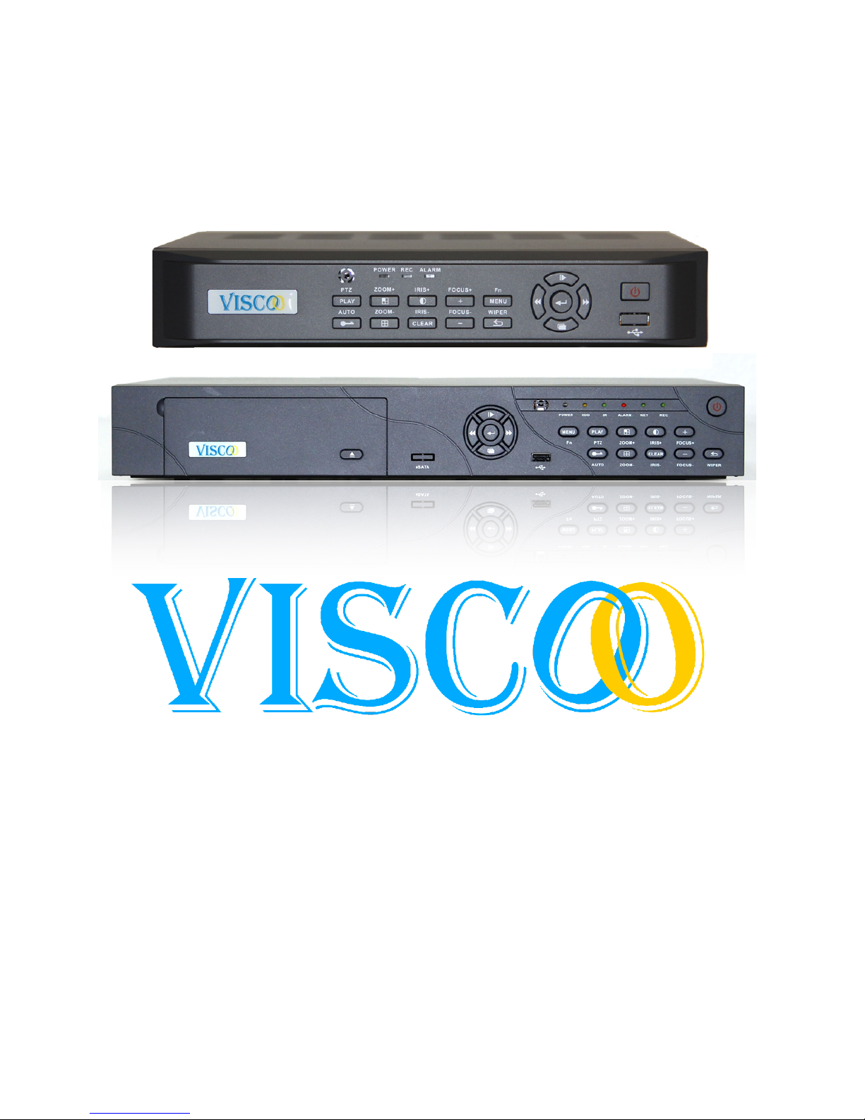
English User Manual
Viscoo Enterprises Ltd.
October 2011
Page 2

2
Changes can be made without prior noticy. All rights reserved.
© Viscoo Enterprises Ltd. – www.viscoo.nl
Preface
Thank you for selecting our products. We will try our best to offer the best service for you. This
manual applies to the VIS-XXXX Series, and we take the VIS316D as a sample in this manual. This
manual applies to DVR7000series, and we take 16 channel DVR (DVR7016LH) as a sample. In this
series, different product models configuration will have a little difference, and their might be
differences between product functionality and operation.
This manual can only be used for reference. We will not provide any new information separately for
later firmware updates. The updating files will be added into the new edition of the user manual and
it will also be posted our website in the download section. This user manual might contain some
misprint or inaccuracy. We sincerely hope for feedback and comments to let us correct and improve
this booklet in a subsequent edition.
Page 3

3
Changes can be made without prior noticy. All rights reserved.
© Viscoo Enterprises Ltd. – www.viscoo.nl
List of content
Preface ..................................................................................................................................................... 2
1. Introduction ........................................................................................................................................ 5
1.1 Summary........................................................................................................................................ 5
1.2 Product introduction ..................................................................................................................... 5
2. Installation ........................................................................................................................................... 7
2.1 Installation surroundings ............................................................................................................... 7
2.1.1 Details of installing the HDD ................................................................................................... 7
2.2. Packet controle ............................................................................................................................. 7
3. Panels .................................................................................................................................................. 7
3.1 The backpanel................................................................................................................................ 7
3.2 USB Backup interface .................................................................................................................... 8
3.3 Network Interface ......................................................................................................................... 8
3.4 Alarm Input/Output connection .................................................................................................... 8
3.5 The frontpanel ............................................................................................................................... 9
3.6 Mouse controle ........................................................................................................................... 10
3.7 IR remote controle ...................................................................................................................... 10
3.8 Menu description ........................................................................................................................ 11
4. Operation of the unit ........................................................................................................................ 13
4.1 Power on / in and out logging / outlogging ................................................................................. 13
4.1.1 Keystroke in- / outlogging .................................................................................................... 13
4.1.2 Log into the system .............................................................................................................. 14
4.1.3 Log out of the system ........................................................................................................... 14
4.1.4 Mainmenu ............................................................................................................................ 14
4.2 General settings of the recorder ................................................................................................. 14
4.2.1 General settings .................................................................................................................... 14
4.2.2 Time setup ............................................................................................................................ 15
4.3 Recording setup ........................................................................................................................... 15
4.3.1 Recording parameters .......................................................................................................... 15
4.3.2 Manual recording ................................................................................................................. 16
4.3.3 Timetable recording ............................................................................................................. 16
4.4 Output settings ............................................................................................................................ 17
4.4.1 Screen settings ..................................................................................................................... 17
4.4.2 Preview of the digital zoom .................................................................................................. 18
Page 4

4
Changes can be made without prior noticy. All rights reserved.
© Viscoo Enterprises Ltd. – www.viscoo.nl
4.4.3 Sequence Cruise ................................................................................................................... 18
4.5 Alarm settings .............................................................................................................................. 18
4.5.1 Motion detection .................................................................................................................. 18
4.5.2 Alarm Sensor setup .............................................................................................................. 19
4.5.3 Alarm Output ........................................................................................................................ 20
4.5.4 Email Setup ........................................................................................................................... 20
4.6 COM Setup................................................................................................................................... 21
4.6.1 COM ...................................................................................................................................... 21
4.6.2 PTZ ........................................................................................................................................ 21
4.7 Network settings ......................................................................................................................... 22
4.7.1 IP Setup ................................................................................................................................. 22
4.7.2 DDNS ..................................................................................................................................... 22
4.7.3 PPPOE ................................................................................................................................... 23
4.8 Playback ....................................................................................................................................... 23
4.9 System Management ................................................................................................................... 24
4.9.1 User Management ................................................................................................................ 24
4.9.2 Backup control ...................................................................................................................... 25
4.9.3 Hard disk Management ....................................................................................................... 25
4.9.4 Back to default settings ........................................................................................................ 26
4.10 System Informatie ..................................................................................................................... 26
4.10.1 System Informatie .............................................................................................................. 26
4.10.2 Recording status ................................................................................................................. 26
4.10.3 Alarm Status ....................................................................................................................... 26
4.10.4 Online Status ...................................................................................................................... 27
4.10.5 Log Information .................................................................................................................. 27
4.11 Software Upgrade ..................................................................................................................... 27
4.11.1 Client Software Upgrade .................................................................................................... 27
4.11.2 USB Upgrade ....................................................................................................................... 28
4.12 Restoration after power outage ................................................................................................ 28
Appendix 1: Internet Explorer operation instructions ..................... Fout! Bladwijzer niet gedefinieerd.
1. LAN Configuration for IE Browse ................................................................................................... 28
2. WAN operation instructions .......................................................................................................... 29
Appendix 2: Net DVR – Questions and Answers .............................. Fout! Bladwijzer niet gedefinieerd.
Issues related to starting, self-testing and downtime ....................................................................... 29
Page 5

5
Changes can be made without prior noticy. All rights reserved.
© Viscoo Enterprises Ltd. – www.viscoo.nl
Issues related to screen image .......................................................................................................... 30
Issues related to client en remote functions ..................................................................................... 30
Issues related to recording, video data and backup ......................................................................... 31
Issues related to alarm PTZ control ................................................................................................... 32
1. Introduction
1.1 Summary
These recorders are designed to record audio and video data. The DVR’s have an embedded H.264
compression format. The embedded RTOS and processor to realize all functions like video and audio
acquisition and compression, storing, remote control, Multi-PTZ control and alarm in a single board.
This series DVR achieve an integrated host to a single plate structure, which ensure that the DVR can
be easily integrated and performs reliable. The DVR adopts the latest file system, which named MFS,
it’s the latest file system which is based on the Microsoft FAT32 system format. It is an innovative
and dedicated DVR file system. It won’ t create the disk defragment in a long run; Logical stream
media operation, fast response; Add the key information verify protection, avoid the key area of the
HDD damage. This DVR system supports USB2.0 high-speed backup, mouse ,keyboard operation ,etc.
1.2 Product introduction
Model
VIS304
VIS308
VIS316
Housing
1 U
Operation
System
Linux
Video Format
1 D1 + 3 CIF
1 Channel CIF/D1
adjustable, other channels
are CIF
CIF
Video Output
1 BNC Video Output
1 VGA Video Output
Audio Input
2 audio Input
Audio Output
1 BNC audio Output
Microphone
3.5mm MIC Interface
Total Frames
PAL : 100 fps / NTSC :
120 fps
PAL : 200 fps / NTSC :
240 fps
PAL : 400 fps / NTSC :
480 fps
Compression
Video: H.264 / Audio: G.711A
Record
Resolution
CIF: 352 x 288 (PAL) 25fps / 352 x 240 (NTSC) 30fps
D1: 704 x 576 (PAL) 25fps / 704 x 480 (NTSC) 30fps
Live Resolution
BNC: D1, 704 x 576 (PAL) / 704 x 480 (NTSC)
VGA: 1024*768
Playback
4D1 (6fps per channel) or
1CH D1 + 3CH CIF
Playback simultanously
1D1 Real-time + 7
Channels CIF Playback
simultanously
16 CIF real-time
Playback simultanously
Image Quality
6 Niveau's Optionally
Page 6

6
Changes can be made without prior noticy. All rights reserved.
© Viscoo Enterprises Ltd. – www.viscoo.nl
E-Mail Alarm
Support
Mobile phone
Support (Windows Mobile, Symbian, iPhone, BlackBerry, Android)
Dual Stream
Support
HDD
1 SATA Interface (Support Max. 2TB)
Backup
USB 2.0 / Remote Backup
Network
RJ45 10M/100M Ethernet Interface
I/O Interface
USB for mouse
Other Functions
PPPoE / DHCP / DDNS / Network Time Protocol / BNC Sequence
Power Supply
220±30% V, 50±3% Hz / 110±20% V, 60±3% Hz
Power
Consumption
6.5W (Without HDD)
7W (Without HDD)
10W (Without HDD)
Work
Temperature
-10℃ ~ +55℃
Humidity
10% ~ 90%
Dimensions
325mm*200mm*55mm
Weight
4KG (Without HDD)
Model
VIS308(D)
VIS316(D)
VIS324(D)
Casing
1.3 U
Operation - system
Linux
Video Format
CIF / D1 Instelbaar
CIF
Video Input
8 ch video input
16 ch video input
24 ch video input
Video Output
1 BNC Video Output
1 VGA Video Output
Audio Input
8 ch audio ingang
16 ch audio ingang
8 ch audio ingang
Audio Output
1 BNC audio Output
Microphone
3.5mm MIC Interface
Total Frames
PAL : 200 fps / NTSC : 240 fps
PAL : 400 fps / NTSC : 480 fps
PAL : 600 fps / NTSC : 720
fps
Compression
Video: H.264 / Audio: G.711A
Recording
Resolution
CIF: 352 X 288(PAL)25fps / 352 X 240(NTSC)30fps
D1: 704 X 576(PAL)6fps / 704 X 480(NTSC)7fps
Live Resolution
BNC: D1, 704 X 576(PAL) / 704 X 480(NTSC)
VGA: 1024*768 / 1280*1024 / 1440*900
Playback
All channel playback and seperate playback (CIF/ D1)
16ch playback CIF
Image quality
6 Niveau's Optionel
E-Mail function
Supported
Mobile telephone
Is supported (Windows Mobile, Symbian, iPhone, BlackBerry, Android)
Dual Stream
Wordt ondersteund
HDD
2 SATA Interfaces
(Max 2TB per connection)
2 SATA Interfaces
(Max 2TB per connection)
2 SATA Interfaces
(Max 2TB per connection)
Alarm Input
8 Alarm Input
16 Alarm Input
24 Alarm Input
Alarm Output
2 Alarm Output
Backup
USB 2.0 / Remote Backup
USB 2.0 / Remote Backup / USB DVD Backup
Network
RJ45 10M/100M Ethernet Interface
I/O Interface
RS485
Page 7

7
Changes can be made without prior noticy. All rights reserved.
© Viscoo Enterprises Ltd. – www.viscoo.nl
USB
Other functions
Watchdog / PPPoE / DHCP / DDNS / Netwerk Time Protocol / BNC Sequence
Power
220±30% V, 50±3% Hz / 110±20% V, 60±3% Hz
Power useage
8W (Without HDD)
10W (Without HDD)
10W (Without HDD)
Operating Temp.
-10℃ ~ +55℃
Humidity
10% ~ 90%
Size
405mm*310mm*55mm
Weight
5.5KG (Without HDD)
2. Installation
2.1 Installation environment
Operating temperature is -10℃ ~ +55℃
The unit must be placed horizontal during installation and use.
It is recommended that the unit is placed in a well ventilated area for use.
The unit should be at least 6 cm removed from the wall for an adequate cooling of the unit.
If the unit is moved to a much hotter area it will shorten the life of the unit.
Do not touch the powerswitch with wet hands.
Make sure the device is connected to Ground in order of minimal shock risk.
Make sure the power adapter is stable, prevents an abnormale voltage drop.
Make sure no pieces of metal or liquids fall into the unit, this can cause a short circuit.
The unit will not record when no hard disk is present in the device.
Make sure you also keep the machine clean inside, this will expend the lifetime.
Don’t connect or disconnect devices with the unit on, this prevents damage to the unit.
If you turm of the unit use the switch on the frontpanel of the unit.
When you finished installing the device, you will see that he recognizes the HDD. You must
format the HDD otherwise the unit will keep beeping. If you use a HDD from a PC then it
should already be formatted to FAT32 before placing it in the unit.
2.1.1 Details of installing the HDD
1. Recommended speed is 7200rpm.
2. The capacity should be at least 32GB or up to 2Tb.
3. The cables should be properly connected.
2.2. Check package
When you open the package make sure it is not damaged. If it is damaged, please contact your
dealer. If the device makes a damaged impression you should also contact your dealer.
3. Panels
3.1 The backpanel
Page 8

8
Changes can be made without prior noticy. All rights reserved.
© Viscoo Enterprises Ltd. – www.viscoo.nl
Video in: connect your camera’s here.
Video out: connect your outgoing cables here for monitor or other connections.
Audio in: connect your audio cable here if you use audio.
Audio uit: connect your outgoing audio here for recording or other use.
VGA: connect your VGA monitor here.
MIC: connect your microphone here.
USB: this is the USB port for connecting a pc-mouse or a USB backup disk.
Ethernet: RJ45 internet connection.
Alarm: on this RS-485 connector you can connect the ptz RS-485 wires and alarm in/output wired.
12V DC voeding: 12 Volt power input.
On/Off: the switch for turning on/off the unit.
3.2 USB Backup interface
You can make a backup on your USB stick or USB backup HDD. You will need a USB device larger then
512Mb and FAT32 formatted.
3.3 Netwerk Interface
There is an RJ45 10M/100M adaptive ethernet interface available that allows the DVR to connect to
your PC or network. The ACT and LINK led’s indicate the status by the following:
Link (network speed indicator) from --- to --- 100M/10M
ACT (sending and receiving indicator) flasking means it will receive and send data.
If the you connect the DVR directly to the PC you need to use a cross-cable, when you connect the
DVR to your router you can use a parallel cable.
3.4 Alarm Input/Output connection
Alarm input: the input resistance is 22KOhm, the voltage for no 3.0-4.18Volt. If the voltage becomes
more then there is an alarm going on.
Alarm Output: Relay (240VAC/7A, 125VAC/10A, 28VAC/10A) normaly the relay is opened when an
alarm follows the relay will close. The DVR has a 12Volt output for a sensor.
If the sensor is too far away, you will need to suply it with a power suply on it´s own. The DVR cannot
suply a sensor over a long length of cable.
Page 9
9
Changes can be made without prior noticy. All rights reserved.
© Viscoo Enterprises Ltd. – www.viscoo.nl
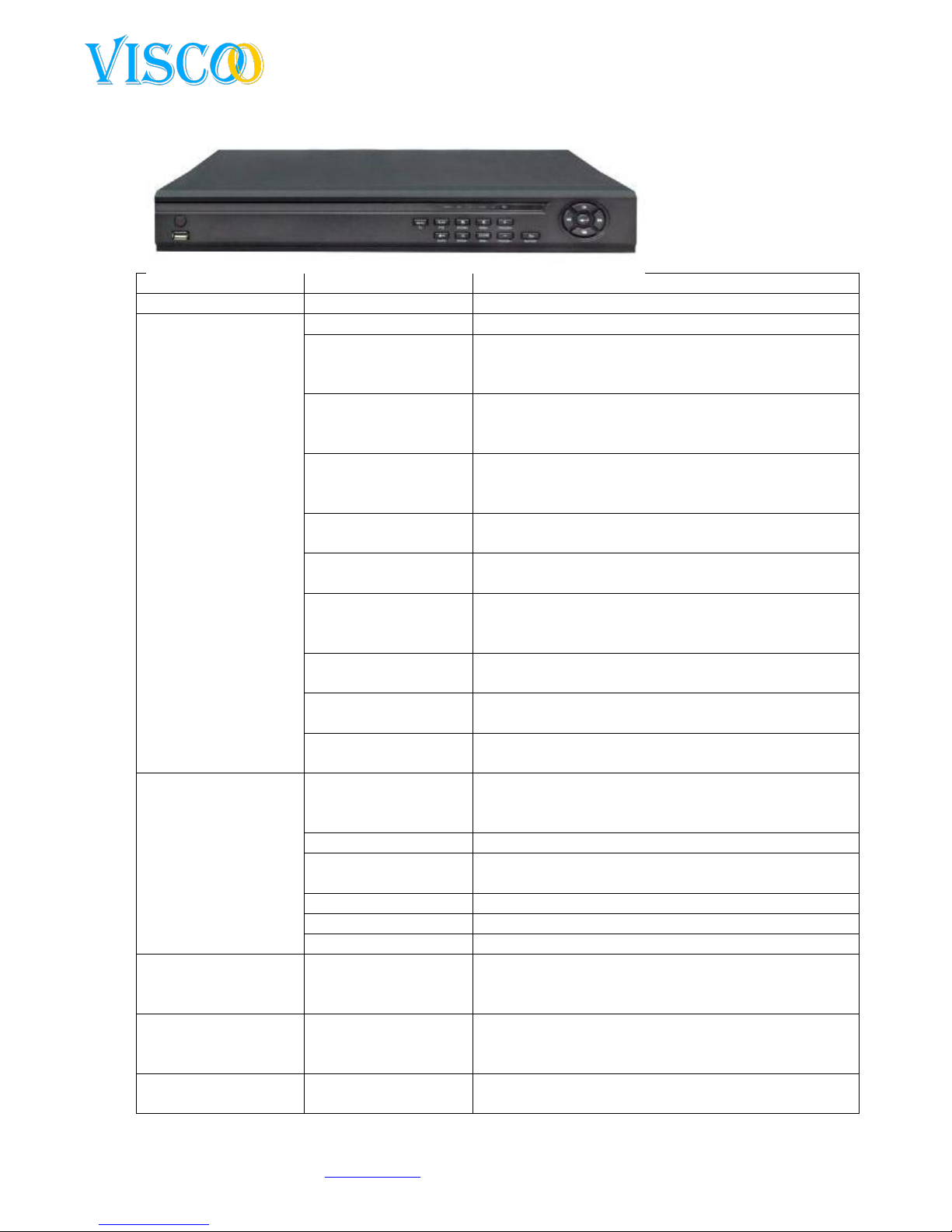
3.5 Het voorpaneel
S.N.
Name
Function
1
Power
Turn device on-off
2 Function buttons.
Menu
Main menu recorder setup
Playback(PTZ)
1. Press to gain access of the recording list, press
again to cancel.
2. If you press long you will ge tinto the PTZ mode.
Lock (auto)
1. Allows you to enter your login and lock the
system up.
2. When in PTZ mode this means `auto`.
Video Shift (Zoom+)
1. Allows you to move the image in real/time
playback.
2. When in PTZ mode this mean`zoom in`.
Video Format (Zoom-)
1. Switching between different video formats.
2. When in PTZ mode this means `zoom out`.
Image (Iris+)
1. Change setting according to each channel.
2. When in PTZ mode this means “iris +” .
Clear (Iris -)
1. Add and remove.
2. Alarm reset.
3. When in PTZ mode this means “iris –“
Up (Focus +)
Menu up.
When in PTZ mode this means “focus +”.
Down (Focus -)
Menu down.
When in PTZ mode this means “focus –“.
Return (Wiper)
Back to menu before.
When in PTZ mode this means “wiper use”.
3 Indication lights
Power
If this light is green it means that the device is in
operation mode, the light turns amber it is in standby
mode. Light off, the unit is off.
HDD
When light is flashing the HDD is in operation mode.
IR
When this light turns on, you are using the remote
controle unit.
ALARM
Light on, then there is an alarm going on.
REC
Light on, the unit is recording.
NET
Light on, someone is logged in through the internet.
4 Arrow buttons
Slow playback
1. Moving the cursor.
2. Slowmotion play.
3. When in PTZ mode this means “up”.
Frame on
1. Moving the cursor.
2. Frame on.
3. When in PTZ mode this means “down”.
Rewind
1. Moving the cursor.
2. Rewind.
Page 10

10
Changes can be made without prior noticy. All rights reserved.
© Viscoo Enterprises Ltd. – www.viscoo.nl
3. When in PTZ mode it means “left”.
Fast forward
1. Moving the cursor.
2. Fast forward.
3. When in PTZ mode it means `right`.
Ok/Play/Pauze
1. Select.
2. Play and pause.
3.6 Mouse control
You can also use the Mouse to control the device. This has many advantages and operating is a lot
faster and easier.
Action:
Result:
Right Mouse click
If you are already logged in, the result is a
shortend menu that will be displayed.
If you are not logged in, the password screen will
appear here, please enter 888888. This is the
deafault password. The deafault username is
`admin`.
If you are in a menu and you press the right
Mouse button you will return to the menu
before.
When you enter the date you get a software
keyboard, then press the right Mouse button it
will disapear.
Left Mouse click
When pushing the left button a menu will apear.
When pushing the icons in the menu you will go
to that menu item.
Controle and adapt the motion detection area.
An easy control for numbers and letters.
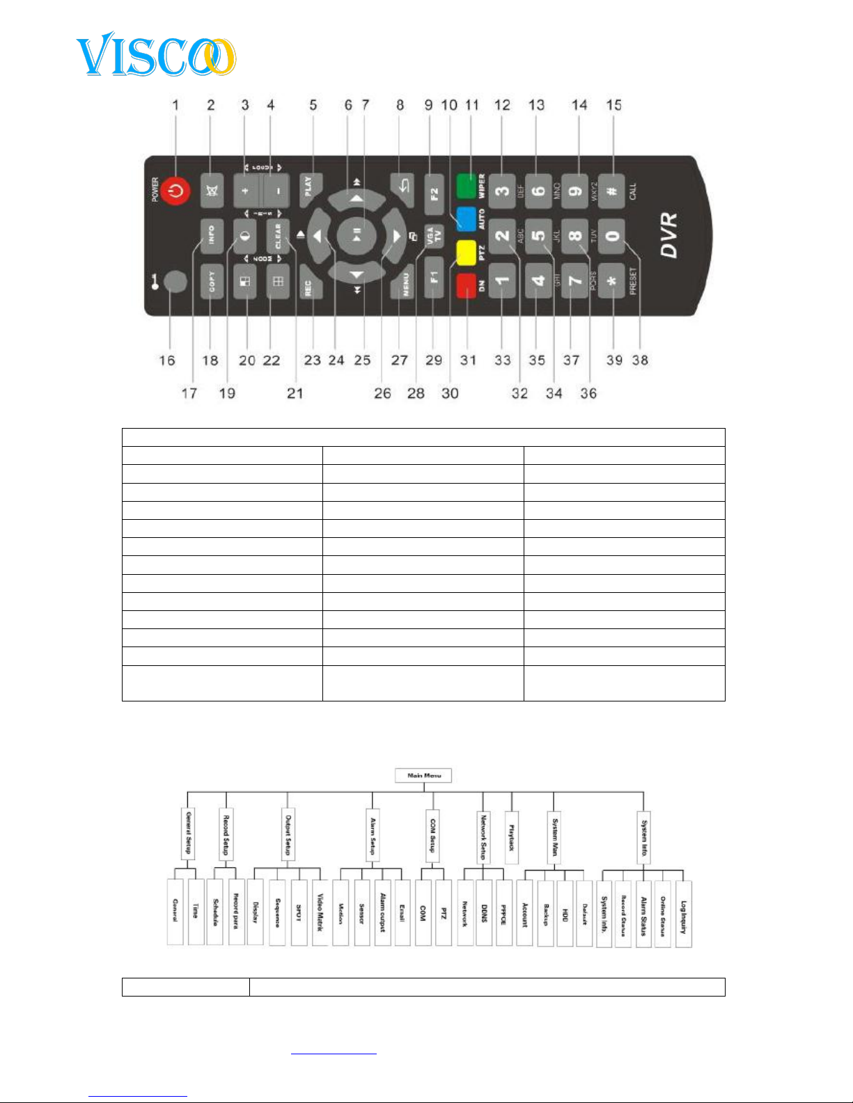
3.7 IR Remote control
Page 11
11
Changes can be made without prior noticy. All rights reserved.
© Viscoo Enterprises Ltd. – www.viscoo.nl
Betekenis toetsen:
1.Power
14.9/WXYZ
27. Menu
2.Sound off
15. Call
28. VGA/TV
3.+, focus +
16. Log in/Log Off
29. F1
4. -, Focus -
17. Information
30. PTZ
5. rewind
18. Backup
31. Server Index
6. forward
19. Image / iris +
32. 2/ABC
7. Ok, play and pause
20. Shift / Zoom+
33. 1
8. back
21. Clear / iris -
34. 5/JKL
9. F2
22. Format / zoom -
35. 4/GHI
10. Auto
23. Record
36. 8/TUV
11. Wiper
24. up , Slow Motion
37. 7/PQRS
12. 3/DEF
25. left en backwards.
38. 0
13. 6/MNO
26. go down and frame
forwards.
39. * , Preset
3.8 Menu description
Menu
Instruction:
Page 12

12
Changes can be made without prior noticy. All rights reserved.
© Viscoo Enterprises Ltd. – www.viscoo.nl
General settings
General settings
1. Dispay contrast settings.
2. Video format ( PAL, NTSC).
3. Recording overwrite.
4. Automatic close.
5. Resolution.
6. Language selection.
Time settings
Time and date settings.
Recording settings
Schema opname
Settings for time tables of recordings.
Recording parameters
1. Recording type: manual, table,
motion and alarm.
2. Define: CIF
3. Bitrate type: CBR, VBR
4. Bitrate grote: 100K,
128K,256K,512K, 1M
5. Picture quality.
6. Video Frame
7. Audio
8. Network, bitrate, quality, audio
Output settings
Display settings
1. Channel name settings.
2. Video marking.
3. Channel doubling.
4. Date setup.
5. Different OSD setup.
6. Video parameters.
7. Video input adjustment.
Sequence settings
Several sequence settings for live display
Video Matrix
Matrix settings
Alarm Setup
Motion detection
1. Alarm schedule.
2. Sensitivity levels (1 tot 5, 5 is the
highest).
3. Detection area settings.
4. Video loss alarm.
5. Channel doubling.
Sensor detection
1. Sensor ID.
2. Alarm schedule.
3. Attach to recording channel.
4. Call for PTZ position.
5. Channel doubling.
Alarm Output
1. Entire screen.
2. Buzzer output.
3. Alarm time.
4. Alarm type.
5. Recording time.
6. Alarm output doubling.
Email settings
Possible events input.
Network settings
IP settings
Server name settings, DNS Server, IP adress
and network ports.
PPPOE
Dial up settings and password settings.
DDNS
choose DDNS server.
COM setting
COM settings
Keyboard adress, type series, COM, device,
Page 13

13
Changes can be made without prior noticy. All rights reserved.
© Viscoo Enterprises Ltd. – www.viscoo.nl
baudrate, date bit, stop bit and parity bit
PTZ Setup
PTZ Protocol, speed en adress code
System
management
Users management
1. Adding and removing of users.
2. Changing the different settings for
the users.
Back up settings
Supported backup
HDD Management
Shows state of all HDD in device.
Factory defaults
Reset device to all factory defaults.
Systeem
informatie
System information
Shows all Information about the system.
recording Status
Shows recorded Information from each
channel.
Alarm status
Shows all Information from each alarm
from each channel.
Log information
Shows log Information.
Menu of the right
Mouse button
Mainmenu
To mainmenu.
Changes from channel
Changes from channel
Video zoom
Directly to live zoom in
PTZ
To PTZ menu
Alarm reset
Resseting the alarm
Video parameter
Video parameters settings
Log off
Log off
Shutdown
Shutdown device
Sound mute
Turn of sound
Restart
Restart the DVR
USB Update
Update theDVR
4. Device control
4.1 Power on / log in & out / log off
Power on: when you have connected the power cable, the light indicator will turn on to its standby
status. After pushing the power button on the remote controler for 3 seconds the DVR will turn on.
Power down: when the system is running, press the power button on the remote controler. Confirm
that you want to shut down the system, not long after that the systen will return to standby mode.
Login / logout:to prevent unauthorized users to operate the device and make unwanted changes to
the system settings a login and auto logout system is build in the unit.
4.1.1 Keystroke login / logoff
When multiple DVR’s simultaneously at one point are being used other machines besides the one
you use could be effected by the remote controler, therefore each DSVR has its own personal remote
code. Under the button system managment from the local menu you kan fill in the serial number
corresponding to each remote and DVR.
Note: if the remote did not respond, one must check whether the feature and options are set
correctly.
Page 14
14
Changes can be made without prior noticy. All rights reserved.
© Viscoo Enterprises Ltd. – www.viscoo.nl
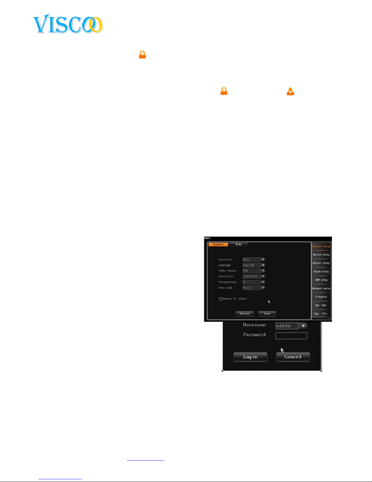
4.1.2 login in to the system
When the system is logged off “ ”, push the login/lock button on the remote control orthe right
Mouse click. Then the next screen will come up asking for a user and a password to contineu:
Enter uour username and password. The user with the highest rauthorities is on top. Once the
correct Information is entered you press enter. Nect the incon “ ” will be adjusted bij “ ” and
the logged in user will be showed. Then one can contineu with the operations one wants to at the
level of the users authorisation.
1. The default username is admin and the password is “888888”.
2. When a three times incorrect password has been given, the device will Block futher input.
Push the “clear” button on the remote control to try the password again.
3. To use the username and password you can push the left button and a software keyboard
will apear. Here you can choose the right username and password.
Note: for safety, we recommend you to immidiatly change the default password to a personal code.
4.1.3 log out of the system and autolock
When logged into the system and the automatic logoff time is exeeced, the system will automaticly
log off. The settings for the auto logoff time can be configured in the “general settings” tab of the
recorder. One can also use the login / lock button on the remote control or by right clicking on the
Mouse.
4.1.4 Main menu
When the user succesfully loggede in, you can press
the menu button on the remote. The main menu is
displayed on the screen.
4.2 Generals settings of the recorder
4.2.1 General settings
Overwrite :
We encourage you to use the overwrite mode of the DVR. If
and when the harddrive is full of data, the DVR will
automaticly overwrite the oldest (by date and time) images.
When this is not set, the DVR will give a alarm sound and the
DVR will stop recording all images because the harddrive is
full.
Auto locking :
When the auto locking is turned on the device will lock after the set period ( 1-10 min.) For instance,
when a lock time of 3 minutes is instituted and nothing will happen with the DVR (movement of
Mouse or other input) the DVR will lock itself and can be unlocked by using your password again.
Video format
The user can choose between PAL or NTSC. For Europe one uses the PAL system input..
Resolution
Page 15
15
Changes can be made without prior noticy. All rights reserved.
© Viscoo Enterprises Ltd. – www.viscoo.nl
Supports VGA output resolution: 800*600, 1024*768, 1280*1024, 1440*900 these are adjustable.
Display contrast
This option provides you to set the transparency of the menu. Number 5 gives you a non transparent
menu, number 1 gives you the most transparent menu.
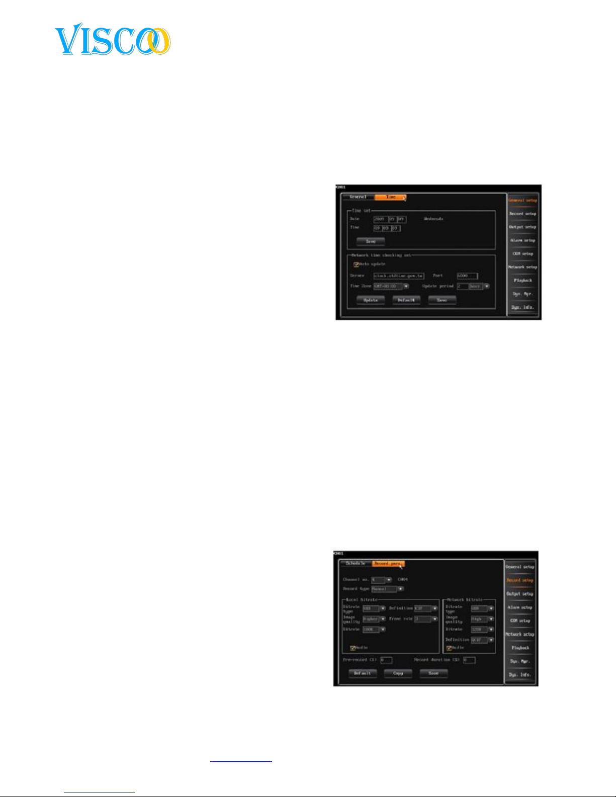
4.2.2 Time setup
Time setup
After logging in, user scan use the “general setup” to navigate to “setup time”. This feature is for the
current system time adjustment. The date is based on
the calender, the dy will change when the date is
changed.(Note: check time before using the system,
all recording use a time and date stamp if not set
propperly one has difficulty to find the right recorded
images).
Netweork time control
NTP: NTP(Network Time Protocol) means that time is
beeing altered by the remote time server..
The standard server is hk.pool.ntp.org, port: 123,tijd
zone is GMT+08:00.
U have to sellect “NTP” before you can use this feature
1. The system support 26 timezones to be set according to the timezone that applies to the location
of the recorder.
2. Its is not recommend to change the default server adress.
3. Ports and timezones are optional.
4.The system is automaticly set to the time interval that the user has selected.
5. The DVR needs access to the internet to activate the NTP..
4.3 Recording settings
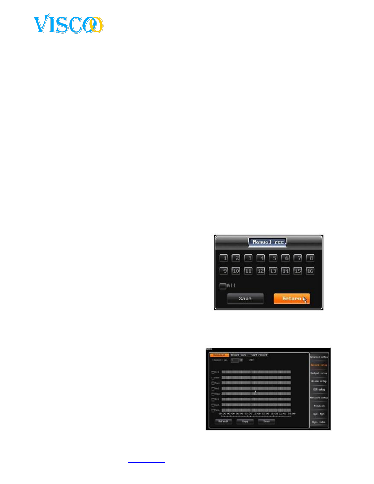
4.3.1 Recording parameters
Before the recording funtion is enabled, it is importained that you First set up the recording
parameters. These settings are related to the video playback functions, backups etc. after logging in
you select “recording setup” and then “record parameter”, use this interface as follows:
Channel nr: the customer can choose the
channel by pressing “+”,”-“ on the remote
control or with Mouse button.
Recording mode: the recording parameters
will be active in the selected recording
modes..
Difine: CIF / D1 is adjustable.
Code stream type: one can choose VBR or
CBR.
VBR: When the video is compressed, the
system can dynamically adjust the compression bit according to the measured light change.
This saves disk space and data will be transfered faster over the internet.
Page 16
16
Changes can be made without prior noticy. All rights reserved.
© Viscoo Enterprises Ltd. – www.viscoo.nl
CBR: The compression bit rate remains constant even when the amount of light changes. The
characteristics of CBR is that you always have good compressed images and that you can
estimate better use of the disk space and network bandwith.
Code stream: set the compression pressure for vast changing images. One can choose
between: 100K, 128K, 256K, 512K, 1M (at CIF is the maximum 1M, Note: the higher the
change, the hogher the bit rate should be set).
Video quality: there are 6 levels to determine the video quality (highest, higher, high,
medium, low, lowest).
Audio: on /off audio switch to activae or deactivate the audio.
Dual Streams
1. The settings for the local stream are applicable to the main stream. These settings affect
the absorption of the main stream and the network stream.
2. The settings for the network stream to the network sub stream. These settings affect the
functionality of the network stream.
Pre-record time: the 4 recording modes support the pre-recording features, the standard
pre-recording time is 10 seconds. The adjustable range is from 0 to 30 seconds. Partly
because of the VBR (variable bit rate), the final pre-recording time differs from the one set.
Delayed recording time: the recording time after a sensor or other alarm is triggered, default
duration is 30 seconds. The range is from 0 to 180 seconds.
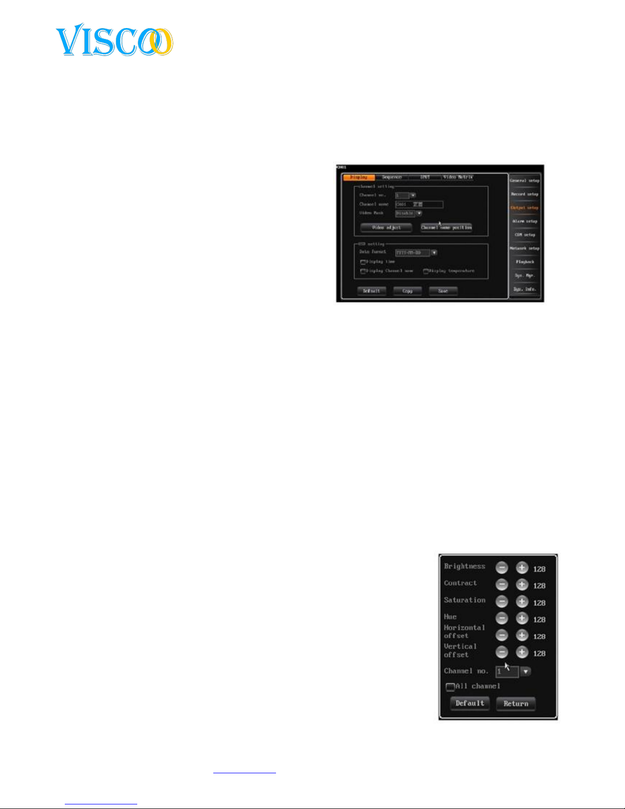
4.3.2 Manual recording
After logging in, click on the menu in the left corner or press the record button on the remote
control. The screen will look like this:
When the channel number is yellow/orange the manual
recording has started, otherwise the number will be a
gray color. When a channel is manually activated it will
contineu recording until you deactive it manually again.
When the power to the system has been cut of the
system will start recording again once the power comes
back with the same settings.
4.3.3 Schedule recordings
in order to set recording schedule, follow the instructions below:
1. Select corresponding channel number.
2. Select the recording day, and set the recording
times in the bar by dragging the Mouse. A
double click on the left Mouse button will
cancel the selection.
3. Choose save to save the settings, the top one
can duplicate the settings to the other
channels.
Page 17
17
Changes can be made without prior noticy. All rights reserved.
© Viscoo Enterprises Ltd. – www.viscoo.nl
4.4 Output settings
4.4.1 Screen settings
After logging in one chooses “main menu” and then”output setup” -> “display setup”, use the screen
as follows:
These settings are used to channel parameters such
as name, mask video, video settings, v=channel
name, position and OSD settings.
1. Channel name:
The channel name can be up to 16
chinese characters and up to 32 english
characters and numbers.
Customize the Mouse: double-click to
open the keyboard. Click on AND to show
the english entry.
Change the remote control: press # to change the input method.
Channel name is fixed to the upper left side of the channel, the channel name position
can be changed by dragging it to the position that is prefered.
When the channel settings are beeing copied the channel name will be left out.
Mask area settings:
In some cases of recordings, user sensitive or private areas of the camera screen can be masked, for
example the position of the pincode input on a ATM.
Each channel support up to 4 masked areas.
Turn on the video mask setting to use this feature. Click on the video area to highlight mask
settings and adjust.
Click the left button to the left corner and then to the right corner.
Set with remote controler; press the direction key to move the cursor, press “ok” to give in
the start position. Then move the cursor to the end position and press”ok”again. Press
“clear” to remove the selected area.
Back to the interface channel settings and press save to store
changed data.
The selected area is active in the live and manual recording modes.
2. Video settings
After logging in one chooses “display setup” and then ‘video para”or use
right click Mouse and then click on “image”.
Standard video parameters: brightness(128), contrast(128),
saturation(128) and hue(128).
Channel nr: used to switch channels, all channel scan be usede
directly.
Adjustment method:
Page 18

18
Changes can be made without prior noticy. All rights reserved.
© Viscoo Enterprises Ltd. – www.viscoo.nl
(1) Select the parameters you want to change, then press the “+”,”- “ button on the remote.
(2) Left Mouse click “+”,”-“ to change the settings, the “+”,”-“ on the interface, increase or decrease
the value.
(3) Video input changes
Video input changes: change the black edges of each channel. The video input is normally with black
edges. The recorder may reduce the black corners by moving the image on the screen in order to
display Information more effectively.
Horizontal line: set the positive.
Vertical line: set.
4.4.2 Preview of digital zoom
Setup method:
After logging in, right click the screen to enlarge. Then click the wheel of the mouse, left click the
start point and then you go to the end and click again. Double click the left mouse button to cancel
the area. You press the right mouse to the digital zoom mode.
4.4.3 Cruise sequence
This function is used to generate a tour among the different channels. Users can use the channel
numbers, sequencing and sequence interval division Speedy choose. The interface looks like this:
Sequence format: 1ch, 4ch, 9ch screen.
Sequence Channel Number: The user can set channel number sequence, the sequence
channel number must be greater than the selected division.
Sequence interval time: range is 3 to 60 seconden.
Note: The sequence function is only active when the system is in "lock" status.
4.5 Alarm settings
4.5.1 Motiondetection
1. After logging in, clicking on the "main menu" and then "Alarm setup", the interface looks like this:
When analyzing the real-time video, the system can determine whether something has changed on
the screen or not. If one likes to have a change that a recording is started, one can set motion
detection.
The user can adjust the settings for motion detection
time pattern, the schedule setting, the detective area,
the alarm output and whether an audio alarm will
activate when it detects movement. The specific setting
for motion detection is done as follows:
(1) After logging in, one goes to "main menu" then
"Record Setup" then to "record parameter"
corresponding to the other channel pre-shooting and
shooting delay settings.
(2) Select the channel which is recording the movement.
Page 19
19
Changes can be made without prior noticy. All rights reserved.
© Viscoo Enterprises Ltd. – www.viscoo.nl
(3) Set the time schedule (The specific settings are
found under the heading schedule recording ).
(4) Select sensitivity: The sensitivity for motion
detection is adjustable and the sensitivity is higher in
proportion as they increase the value of 1 to 5. When
the motion of the current channel is removed, the
system will jump in alarm and start recording. When
the sensitivity is low, such as "1" then the recording
will only start to major change. At "5", the system will
record all changes at small image.
(5) Set the detection area:
Before you activate the motion detection, one would
have to determine the detection area. If the picture is changed in these areas, this is detected, and
enter the alarm state recorder. The yellow highlighted area to detect the field.
- The area set with the remote control is done by using a directional keys to set the startpoint
and the endpoint. Press the confirm button to save your settings. Left Mouse Click to view
the status of the motion detection area to be set. Then you press the return / previous to the
recording settings without saving or you press save / save the settings to activate.
- The area set with the mouse: left click with the mouse for the starting position of the area to
be determined, then click another point to determain the end point. Then the selected area
is shown. Double click left to delete the selection. Then you press the return / previous to the
recording settings without saving or you press save / save the settings to activate.
(6) Alarm Output Setup: The button will turn yellow when the alarm output function is activated with
deactivation the button is gray.
2. Video loss alarm
By default, the DVR is set when a signal interruption occurs, an alarm buzzer is activated. There are 3
ways to set an alarm output, these are audio buzzer and full screen. You can click on information to
see the emergency status.
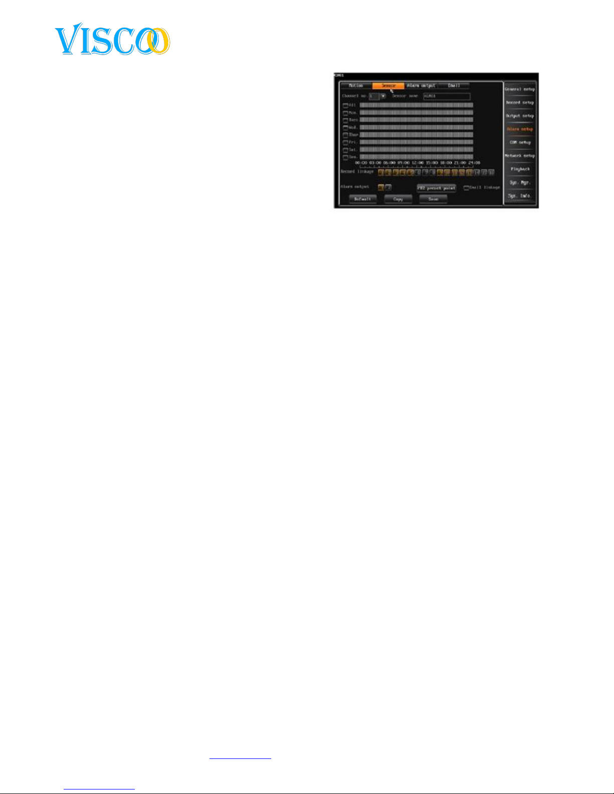
4.5.2 Alarm Sensor setup
The following steps should be performed to setup a sensor:
(1) After logging in, one goes to "main menu" then "Record Setup" and then go for "record
parameter" for the settings interface to open the alarm recording, set the corresponding channel,
pre-recording and the recording time.
(2) Select "Main Menu" then "Alarm setup" and then "sensor", open interface for alarm recording,
the interface looks like this.
(3) Choose sensor type.
(4) Choose sensor number.
(5) Set the active period (the specifics can be found under the piece of chart settings). Left Mouse to
set the start and then drag the mouse to the endpoint.
(6) The recording channel can be linked to an alarm, we recommend that each channel corresponds
to a sensor, so the alarm recording files can be found by channel. A yellow button means that there is
a link for alarm recording, a gray button means there is no link.
(7) Alarm output settings: you can select the alarm output button. (Yellow is on, gray is off).
The system supports a recall to a preset point function when an alarm is triggered. (it is a
requirement that the camera supports preset). The settings you make as follows:
1. Click "PTZ preset point" to PTZ preset interface bands, there you can set the preset point.
(Note: the range for a PTZ preset is 1-255, 255 means close. If you copy the channel settings,
the settings are not copied along with it!) after this one should save to save the data.
Page 20
20
Changes can be made without prior noticy. All rights reserved.
© Viscoo Enterprises Ltd. – www.viscoo.nl
2. In the "COM Setup" interface you can set the communication type, COM device and the baud
rate. In the PTZ setup interface can be the
protocol and address of the PTZ setup.
3. Switch to the channel you want to set the preset
points. Press the "PTZ" button on your remote
to the PTZ controller mode to enter. Then press
"PRESET", enter the preset number as in step 1
and click the preset to save. Return to the
previous menu to cancel.
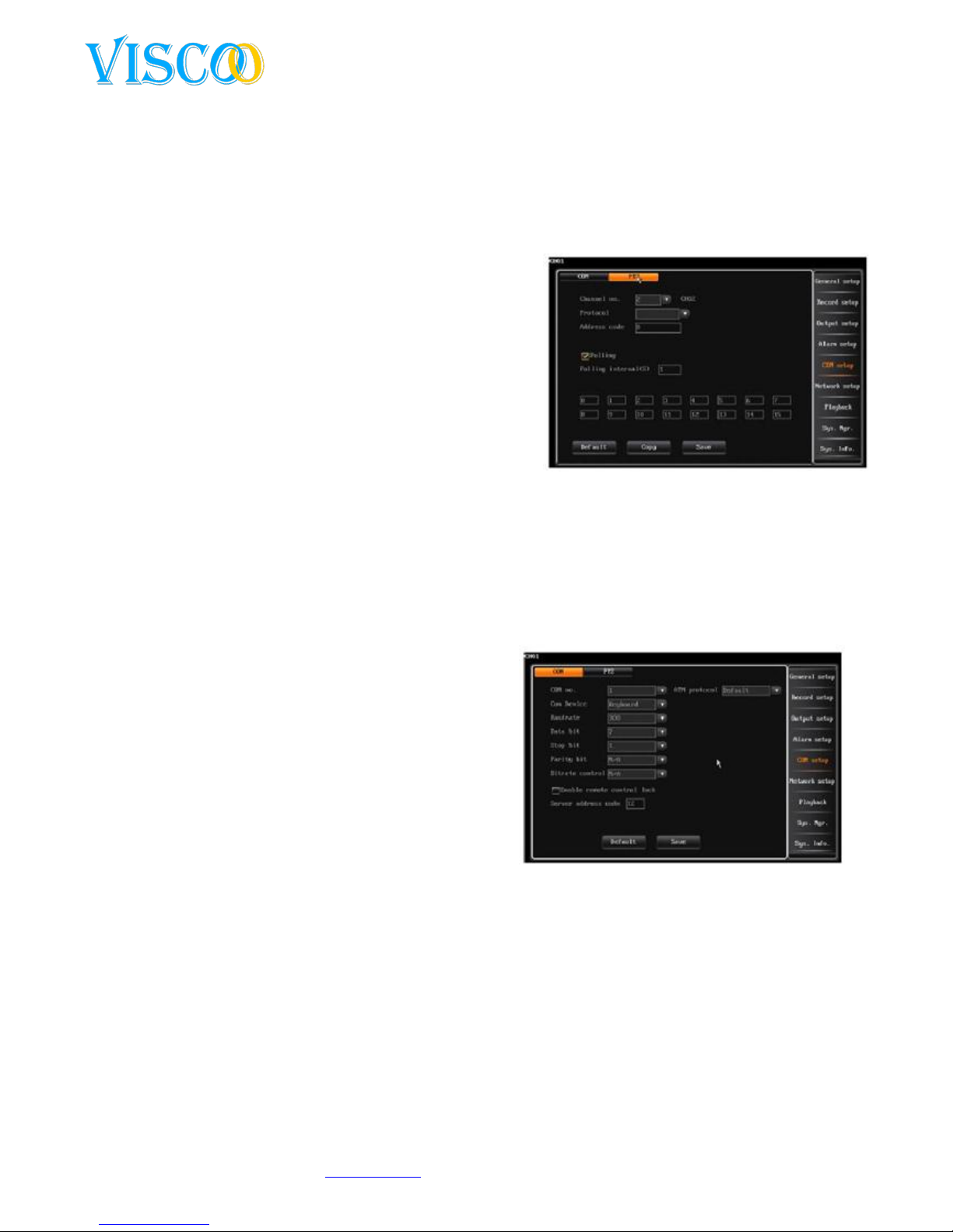
4.5.3 Alarm Output
After logging in, you go to "Alarm setup" and then
"Alarm output" to the alarm output interface. This
interface is as follows:
The "Alarm output" interface contains the following options: sensor type, alarm to full-scheme, to
alarm buzzer, Audio Alarm, Alarm Output Time, alarm output active time.
Sensor type: normaly open, normaly closed.
Alarm to Full Screen: When the system is multiple images, the screen will automatically extend
to the channel when the alarm is activated.
To alarm buzzer: when the alarm is activated, the buzzer sounds.
Audio alarm when the alarm is activated, the audio output is to be activated.
Alarm outputtime: inspection (2~300s),the standaard is 30 seconds.
Alarm active time: the standard schedule is 00:00-23:59 for every day.
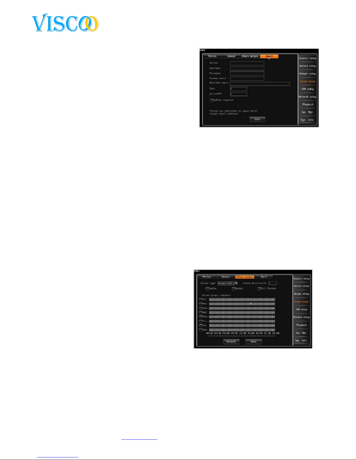
4.5.4 Email Setup
After logging in, it goes through "main menu" to "Alarm Setup" then to "Email Setup" to go, the
interface looks like this:
Email setup settings:
(1) Activate the Email upload, select the related email.
On alarm (video loss, motion detection, sensor
detection) trigger, the DVR will automatically send
emails to an email account.
(2) Set the SMTP server, default is smtp.126.com..
(3) Enter the username and password of the mail
account.
(4) Enter the email adress of the SMTP server.
(5) Enter the email address of the recipient. Multiple
addresses can be placed through a separate stabbing
"," back in place. Up to 256 characters in this window
can be placed.
(6) The default port is 25, on normal conditions no change is needed here.
(7) Set the email upload interval time, which is the time interval to send alarm information to the
target mail. The recorder upload only once every selected time interval, it can take snapshots and
send them in .jpg format.
(8) After saving the settings, the selected recipient (s) will receive the reports of the recorder when
an alarm is activated.
Note: If the mail can not be sent, one must determine whether the recorder has access to the
Internet, and whether the mail server, it can work. Some providers block port 25.
Page 21
21
Changes can be made without prior noticy. All rights reserved.
© Viscoo Enterprises Ltd. – www.viscoo.nl
4.6 COM Setup
After logging in, it goes through "Main Menu" to "COM Setup", the interface looks like this:
Here you can change the settings to other serial devices to pair with this recorder. The recorder has
two options for serial connections, the RS485 and RX. Both serial ports are full duplex terminals that
can receive both data and send. The DVR can be connected to a PTZ, keyboard, serial and other serial
devices simultaneously.
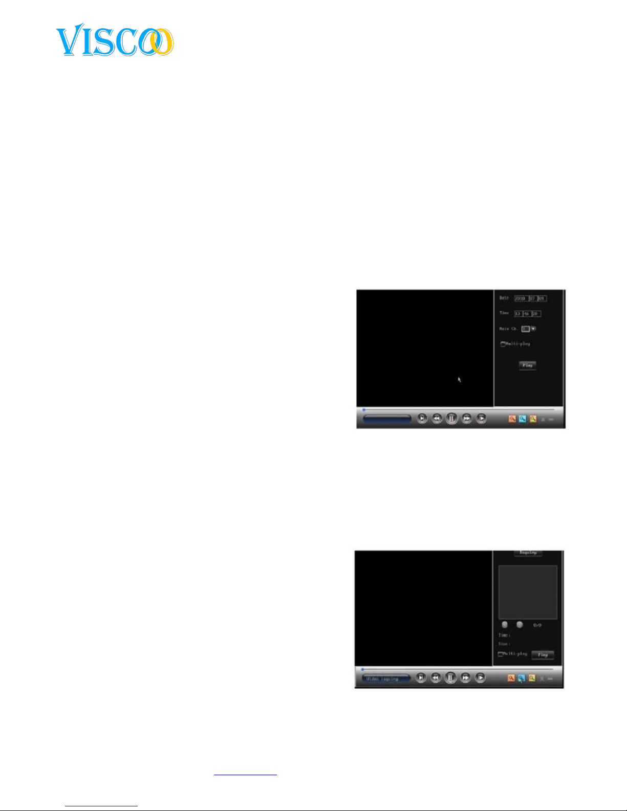
4.6.1 COM
The parameters that can be set for RS485, RX are: baud
rate, data bit, stop bit, check bit, etc. These settings are
used to the COM type. There are 3 options to choose
from: PTZ, keyboard serial and transparent channel.
Baudrate: Set the baud rate for communication
between COM and the other devices such as PTZ,
keyboard's baud rate must be identical with the
DVR system baud rate.
Data bits, stop bit, check bit: Set the data bit, stop
bits and check bit.
The protocol code. Standard is the standard protocol PTZ date 8 bit, check bit is None, Stop bit is 1.
Host address: If a keyboard is connected in parallel with multiple DVRs can use the keyboard
to control multiple DVRs in the various identifier codes.
PTZ Protocol: Set the PTZ protocol with this option, it must correspond to the PTZ camera.
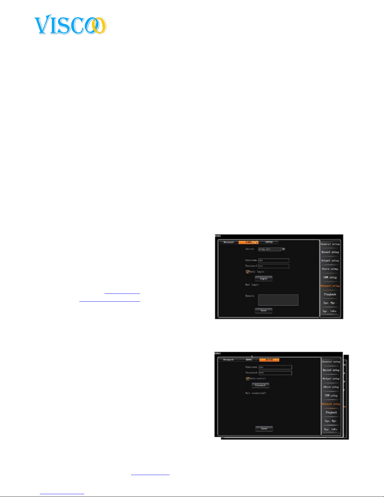
4.6.2 PTZ
The procedure for PTZ settings:
Select the type of COM, COM device and baud
rate in the setup COM interface.
Enter the PTZ setup interface to the protocol
and address of the camera settings. (usually
the first PTZ address "1”).
Note: PTZ protocol, baud rate, address must
be equal to that which is in the PTZ camera.
Switch to the channel for single channel
display, press the "PTZ" button on your remote
control the PTZ mode. You can then use the
remote control the PTZ camera control. Press
"PTZ" button to leave PTZ controller modes.
One can also right-click to terminate the modes.
Set the preset points by using the remote as follows:
Open the PTZ status, press the directional buttons to the PTZ to aim as you want the preset
point, then press "* Preset" at the bottom of your remote and enter the number that you
added would know (eg 1) when the preset number you are calling, the camera will
automatically select the preset position.
Setting and recalling the preset points in the mouse: Open the PTZ status, double left click on
the preset input field to the software keyboard to open and run preset No.. (Such as 1). Right
click to the software keyboard to disappear. Then click on the preset trigger setup. Then you
turn the PTZ to another point and press the "call" button and enter the preset number to
which you want to go. The PTZ camera will automatically go to the set point. Click on return /
next to the PTZ interface to close.
Page 22
22
Changes can be made without prior noticy. All rights reserved.
© Viscoo Enterprises Ltd. – www.viscoo.nl
Multi-sequence preset positions (Note: Only activate the system log is off)
(1) Sequence interval: 0 to 99 seconds.
(2) No Preset.: Each channel can have up to 16 preset positions.
(3) Range of the preset numbers. :001-255, means 255 closed.
4.7 Network settings
After logging in, you go to "Main Menu" to "Network Setup" to open the network interface settings.
4.7.1 IP Setup
The network setup looks like the following:
Auto obtain IP Address: If the DVR is placed behind a router that is set to give out DHCP
adresses according to the network, the DVR will automaticly been given an ip adress from
within the network. This adres will be shown in the network options.
Deactivate DHCP: If no DHCP service available in the LAN, then you can disable this option
and then manually set an IP.
IP settings: The IP address must be unique. There may be conflicts with other servers or
workstations on the same network. The default IP address is 192.168.0.6
Subnet mask code: Used to distinguish different subnets.
Gateway adres: Used to realize communication between different networks, it is necessary
to have a gateway address.
DNS server: Enter the DNS address obtained from the PPPOE provider here. (possibly the
gateway address in this box). When using DDNS, this should be correct). If no DNS is given
you can always use the Google DNS (8.8.8.8) and (8.8.4.4).
Command port: This is the data transmission
port for the client software, default is 8101, port
range 8000.
HTTP port: IE browse port, default is port 81.
Port be changed, you do need to restart the
recorder to be change to be effective.
HTTP port, this is needed to be typed in your
browser: http://IP:port for example
http://192.168.1.10:81
Multicast activate: This function is effective only
for the UDP stream.
Multiple IP adresses: Multiple IP addresses can
be set in a range from 224.0.0.0 to 239.255.255.255, the default is: 239.0.01.
Multiple ports:The default port begins with 8000. Note: If two or more recorders are in a
section iof the network, then you must make sure that the various ports are unique,
otherwise one can not call multiple video
images !
4.7.2 DDNS
The DVR supports DDNS function Viscoo, you can
analyze what the WAN IP directly elected by the ADSL
connection. You can also get the router's WAN IP
address trace. This function supports the domain name
is registered with www.dyndns.com. You can create an
account to a dynamic IP address to automatically
update.
Login at www.dyndns.com to make yoursels a
dyndns DDNS, write down user and password. Select the DynDNS server on your recorder,
Page 23
23
Changes can be made without prior noticy. All rights reserved.
© Viscoo Enterprises Ltd. – www.viscoo.nl
enter the username and password that you created on the website. Save this data and then
you must see the DDNS information after a few minutes.
4.7.3 PPPOE
Select "Network Setup" tab and click the "PPPOE", then you will see the following screen:
PPPOE is one of the ways to connect to a WAN network. This way, you connect to the WAN network
by connecting directly to set up the ADSL provider
Username :ADSL account username.
Password:ADSL account password.
Connect : After you filled in correct the ADSL username and password, you use the mouse to
click the icon "connect / connect" to connect to the WAN network.
Auto Connect: If you choose this option, the system will automatically reconnect to the WAN
network after being disconnected.
Save the password: If you choose this option, the system will automatically save your ADSL
password so you do not have to re-enter again
when you connect to the WAN network.
It shows the network information from the public
network when the ADSL connection is having
successfully connected (such as IP address and
subnet) Press the "save" button to store data.
Next time, the recorder automatically connecting
to the network. (Note: You must manually
connect to the network when you select auto redial on.
4.8 Playback
The system knows two ways to open and recall the playback menu/screen:
(1) Open the playback interface, press the "play" button on the front panel or remote control. Click
on the yellow icon to get accurate time to playback, press again to playback the recording file in the
search interface to display.
(2) After logging in, click "Main Menu" and then "playback" For the playback interface. It looks like
this:
Click on the blue magnifying glass button to list the
recording interface. Here you can select the images in a
certain time period or with a recording type. Click on the
yellow magnifying glass to playback the accurate time.
There are four types of image files: manual,
schedule, motion, alarm. You can press "+" or "-"
button on your remote control or left-click the
file type. The default list consists of all record
types.
Fully channel playback: The system supports
multi-playback (8 channels) function. All
channels are played back in real time. You can
press a number key on your remote to switch to
another channel in the playbackmode.
After a selected time and channel, the system will update the recording data.
Page 24
24
Changes can be made without prior noticy. All rights reserved.
© Viscoo Enterprises Ltd. – www.viscoo.nl
When you select an image file, the start, end are on the bottom of the display file in the
playback interface.
Move the cursor to the file you want using your remote, press "confirm" to playback the file
to start. You can achieve the same with the mouse by double clicking the left mouse button
on the file.
Click page up / down in the relevant category to search across multiple pages.
Right click with your mouse during playback ensures that the playback menu is displayed or
disappears.
Supports digital zoom in playback mode using the
mouse. Go to the movie playback, click the mouse
wheel to select the start, then left at the starting
point seletecten zoom, then drag the mouse to
the end point digital zoom. A square will be
visible, drag the edges to what you want to zoom.
Right click to terminate this mode.
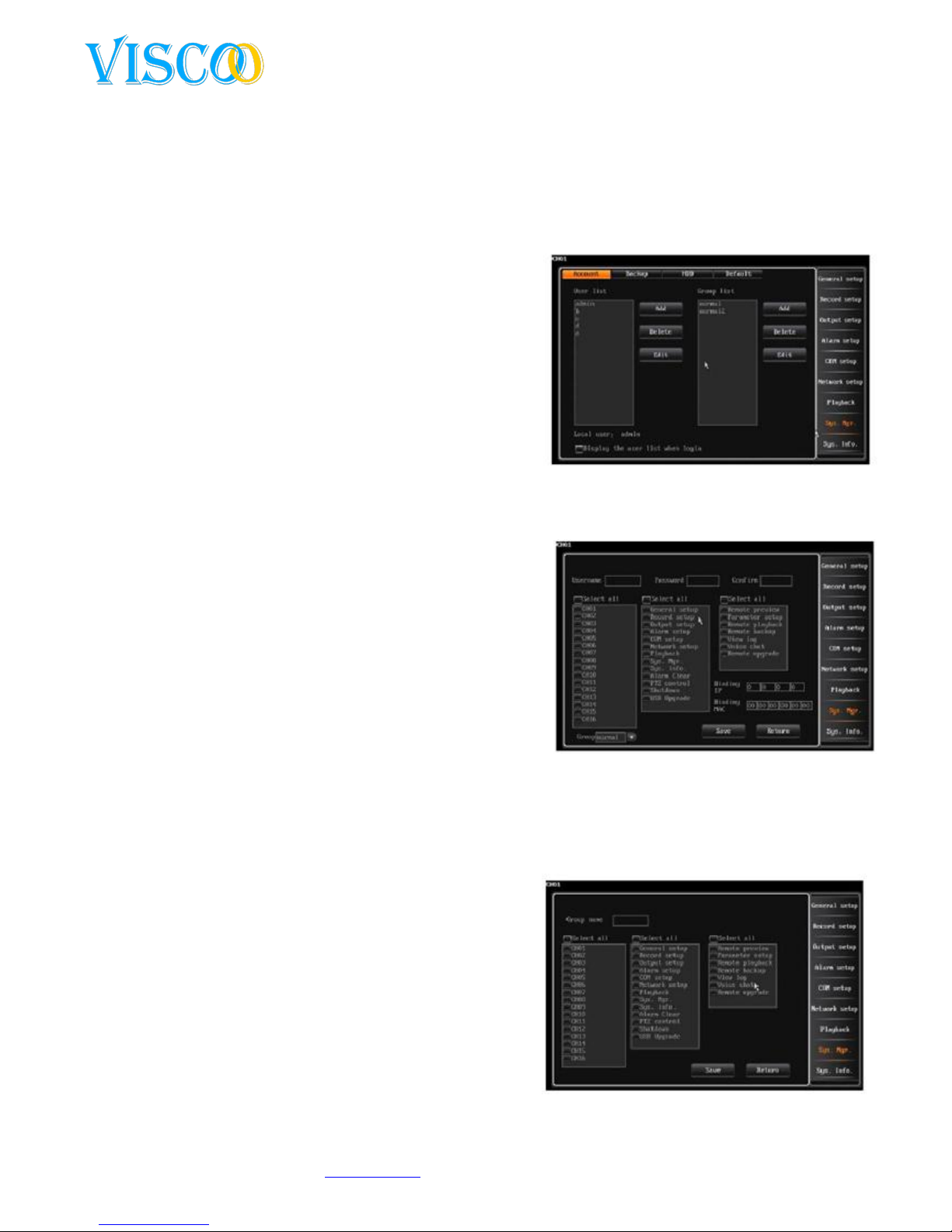
4.9 System Management
Once you are logged in, go to the "Main Menu" to "System
Management", then the system management screen is
shown:
4.9.1 User Management
When the DVR leaves the factory the user and password
settings are in default state. Using for user “admin” and for
the password “888888”. Please changes these settings for
security reasons. The “admin” has the most rights of all the
users and he can make a maximum of 15 other users. All the
rights of the users are admited by the “admin”. For
protrection and security the “admin” should change his
password right after he logs in for the first time.
1. user managment
Adding / removing of users: place the cursor on the
"Add / Add" icon and click on it to create a new user. You press delete to delete a selected
user.
Change password: Use the direction menu on the remote to move the cursor to the user,
press "OK" or double click with your mouse to get intothe interface with the settings.
Supports local and remote settings.
Show the userlist when one tries to log in, use the
"+", "-" on your remote control or click the wheel
on your mouse to select the user. When the
option "display the UserList When login" is off
then the user has to manually fill in its name when
trying to log in.
2. User group
Supported user functions. Each user can belong to a
group, the admin user defined the rights of the user. It
Page 25
25
Changes can be made without prior noticy. All rights reserved.
© Viscoo Enterprises Ltd. – www.viscoo.nl
looks like this:
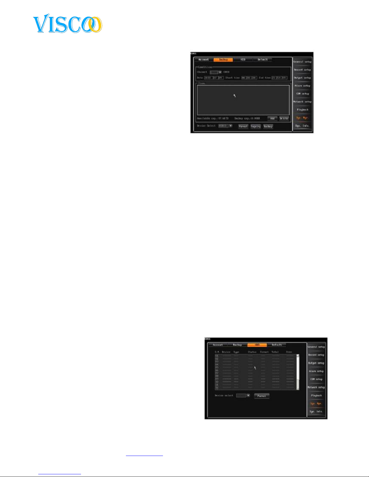
4.9.2 Backup control
There are three ways to backup:
1. Backup file to a remote computer over the
network.
2. USB Disk backup, the USB drive is FAT32 and
larger than 512Mb.
3. Using a CD / DVD burner.
1.file backup
De backup interface looks like this:
The backup function allows the recorded files of 26 different files of different channels at different
times to make at a time. The details for the backup are as follows:
1. Enter the time and channel number.
2. Move the cursor to "ADD" and press confirm. The added recording will be displayed in the
backup list. For multiple capture files you repeat these two steps. When you have added all
files, press the confirm button and then the system will start with automatic backup.
3. You can back up files without waiting
4. Backup file list: Display the files attached to different channels and different time periods.
5. Backup host: The user can specify the name of the host. After setting up the hostname, the
user can "save / save" button to confirm. (Note: The host name can comprise up to 32
characters.)
2. Backup files playback
To play back the backup files, the user needs to open the playback interface and push on the
"inquire" button, select the file and press enter to play.
Backup date: Displays the backup files in the current hard disk partition backup. Move the cursor to
the date icon and press "ENTER", and the file list on the right will show all images in a given time
selection.
Backup file list: Shows backup file information on a particular date.
Note: The user can not use the fast forward mode when the backup files are shown.
4.9.3 Hard Disk Management
After the user logs in, go to the "Main Menu" to "Disk
Management ", the interface looks like this:
The first line show the connected hard disk numbers
The second line show the status of the hard disk. The
third, fourth and fifth lines show the disk space, free
space and partition type information. The bottom line
shows the total capacity of hard disks and the total free
space.
Disc format: System supports only the FAT32 format,
the capacity of the hard drive is above 32G. The system
supports only one partition for backup.
Page 26
26
Changes can be made without prior noticy. All rights reserved.
© Viscoo Enterprises Ltd. – www.viscoo.nl
Format : Select the number of the hard drive, then click the "format " button and press "OK" to
confirm. When you have confirmed it there will be the message on your screen that the hard disk is
formatted.
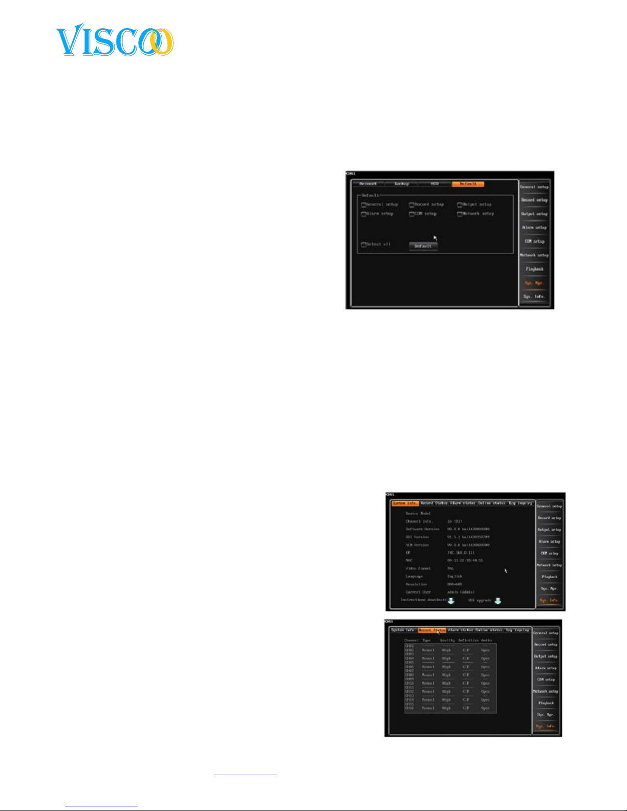
4.9.4 restore to factory settings
The recorder to factory settings is done with the "System Management" and then click on "Default",
the new interface looks like this:
Note: Network IP and port, system time, user and disk
management will not be restored to factory condition.
Default system parameters:
General Parameters: Contrast (5:1), video format
(PAL), Record on write mode (Auto Cycle), hard drive
failure alarm (activated) Open car locking (enabled),
auto lock time 3 minutes, date format (YYYY- MM-DD)
Display channel title (enabled) Display time (Off);
Display Temperature (Operation), switching channels (closed).
Recording parameters: Record mode (All) Encoding stream type (VBR) Encoding stream (512K),
recording quality (High), video frame (25) Audio (Enabled) Transmission encoding stream (512K)
Transmission image quality ( high), Transmission Audio (enabled).
Record Mode: Manual (closed) diagram (closed) Motion (closed) alarm detection (closed).
Netwerk: Auto redial (closed); Auto login(closed)
COM: Baudrate(9600); Data bit(8); Parity bit(non); Stop bit(1); Keyboard adres(1); Protocol
(unknown).
Channel : channel names(reset to default); Video loss alarm (on);
Alarm output(1~2); Video area mask(no mask);Preset poll (closed); Pre-recording tijd (10 seconds);
Delay recording time(30 seconds).
4.10 System Information
4.10.1 System information
In this interface is the software version, IP address, etc, shown:
4.10.2 recording status
The recording Information looks like the following screen:
Here you see with a quick glance of the current status of the
recording system. It shows the recording status of each channel
in any way, the recording quality, definition and audio recording
status (on or off), and whether it is recording. The type of
window, the current recording method to display (manual,
schedule, motion, alarm). Finally the recording quality is also
indicated in this overview.
4.10.3 Alarm Status
Page 27
27
Changes can be made without prior noticy. All rights reserved.
© Viscoo Enterprises Ltd. – www.viscoo.nl
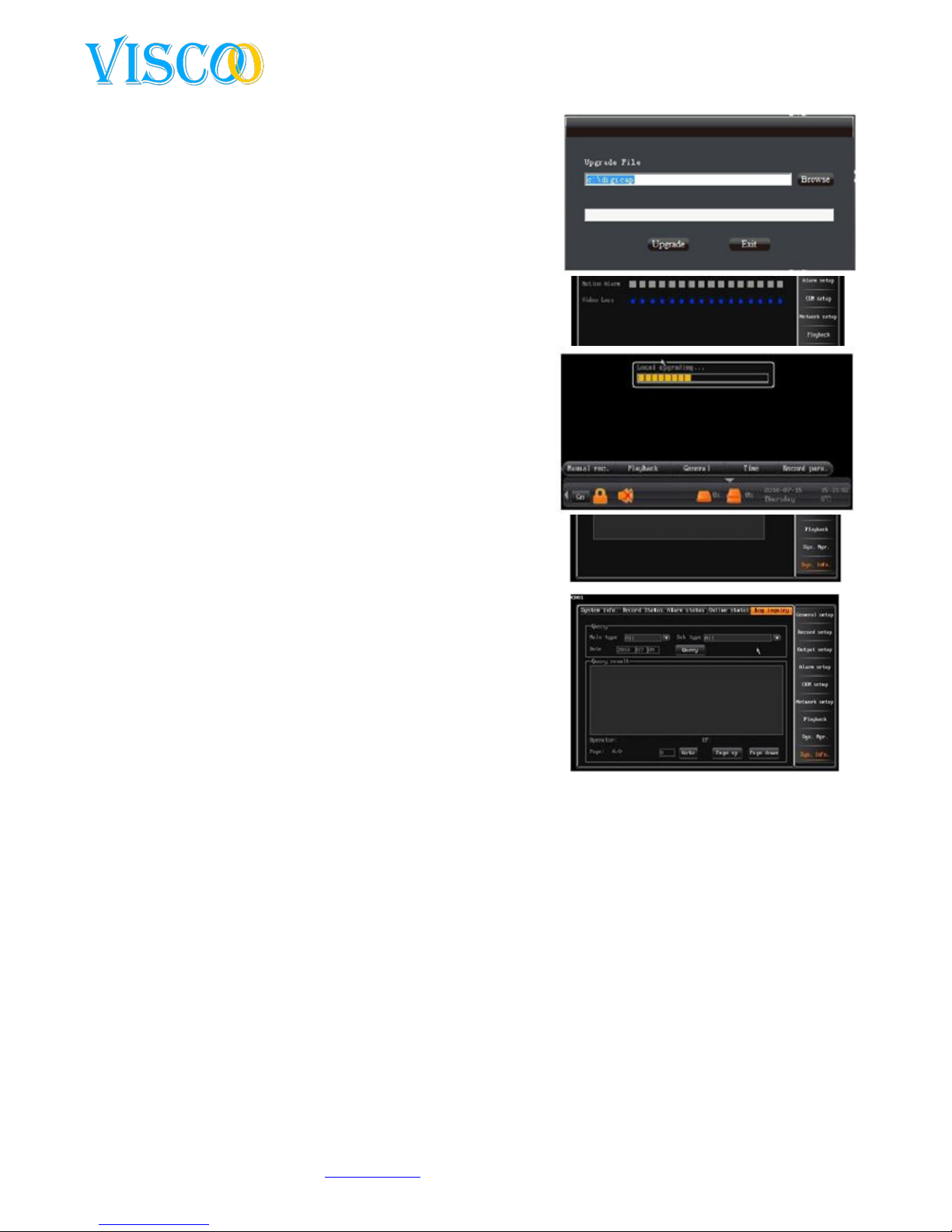
the alarm status Information screen looks like this:
Here is the alarm type that is shown for each individual
channel: sensor alarm (red color), motion alarm (yellow) and
video loss alarm (blue color). You can delete alarms by
pressing the "CLEAR" button on the front of your recorder or
remote control or click the "Clear Alarm" button with your
mouse.
4.10.4 Online Status
Here is the information shown on any remote PC or mobile
phone connected to the recorder. Here you will find
information such as IP address, login and Logout time, etc.
This interface is as follows:
4.10.5 Log Information
The log Information screen looks like this:
At the bottom of the interface is the page number .
The user can click to page up / down to navigate to
another page. The number of rows returned in the
log is unlimited. The log file can not be recognized on
the PC. One can only see this with the client software.
Contents of the log: system on and off, changing the
version log, alarm log, PTZ control log, users and log
out log, changes in system parameters, recording
playback log, backup log, format HDD log user login
client log, etc.
4.11 Software Upgrade
There are two ways to upgrade your digital video recorder. 1.
The PC client software, 2. Via a USB stick directly on the
recorder. Read the following information carefully before you
start an upgrade.
4.11.1 Client Software Upgrade
Please check the version of the DVR before you upgrade so that you can always return to the
older version when the upgrade fails. When the system is running well with almost no
defects, it becomes strongly discouraged to update the system.
If you want to upgrade you must ensure that the power is OK and that the network is stable.
When the update is interrupted, there may be serious flaws in the recorder afterwards.
Please ensure that the upgrade for your device is compatible, check the model number and
whether the interface has a boot and whether it corresponds with all that which is stated on
your recorder. If you do not update correctly, the unit must be returned to the factory, in
your case the office of Viscoo Netherlands BV!
After an upgrade, you can consult the manual for the adjustment of the new version, which
can be downloaded from the website.
Page 28
28
Changes can be made without prior noticy. All rights reserved.
© Viscoo Enterprises Ltd. – www.viscoo.nl
Do not make changes to the firmware, not the name of the firmware, otherwise we take no
responsibility for the product and further upgrades are going to be charged.
Make sure that when you update with the PC client, that the above procedure has been followed
correctly. The procedure for using the PC application to update is as follows:
1. Just connect the DVR to a PC using a network cable or connect via the LAN (watch out for any
IP address conflicts).
2. Before you update, you need to confirm the IP address of the host computer and enter this
in the client software, if asked.
3. After logging in click on "System" -> "Remote Update".
4. Select "Browse", choose the file you want to use for the upgrade.
5. Then you will see the upgrade bar fill with orange / yellow cubes.
6. Wait for 3 seconds, the DVR displays "Finished Transmitting Data. Updating software ... ".
This takes about 2 to 3 minutes before the update is complete.
7. If at the end of the message that the update was successful, the recorder will restart.
8. After the system is restored, the password again is as before.
4.11.2 USB Upgrade
The USB upgrade is as follows:
1. Copy the upgrade.bin to the USB stick.
2. Insert the USB stick into the USB port on the back of the recorder, it will automatically be
recognized and notifide. Then go to system information and click interface USB upgrade.
Then press to confirm the update process.
3. The system now states “ the system is
updating…”
4. When the upgrade is complete there will be
"updated successfully" will appear on your
interface, then press restart to restart the
system. This can be done automatically in some
cases, this idepends on the software version of
the recorder.
5. After the system is restored, the password again
is as before.
4.12 Restore after power failure
When a power outtage has occured, the system will automaticly resume its former state.
Appendix 1: Internet Explorer Operating Instructions
Note: Enable the firewall on low or turn it off. Please turn all ActiveX security settings in Internet
Explorer on, otherwise the component blocked DirectX 9.0 on your PC and can not view the images
on the recorder.
1. LAN Configuration for IE Browser
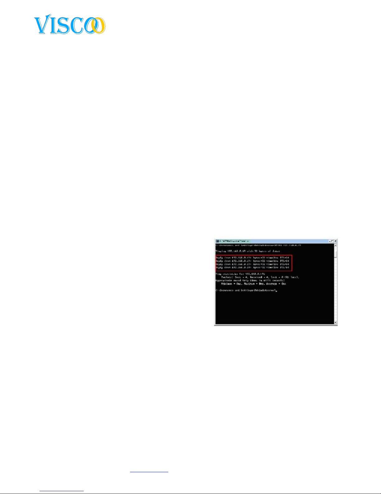
1. “Ping” the host first to confirm that the device is in the network and working.
2. Type the host IP in Internet Explorer and connect to the recorder. Please give in username and
password, if Loggins is successful, you will see the following interface:
Page 29

29
Changes can be made without prior noticy. All rights reserved.
© Viscoo Enterprises Ltd. – www.viscoo.nl
3. Refere to “Client manual” for more information.
2. WAN controle instructions
If a fixed WAN IP address is what leads to the
recorder, then you can directly connect through
the WAN network settings after you have set
the recorder.
The host settings steps are as follows: After
logging in, click on menu, navigate to "Network
Settings" and select the "Dial-up Settings" interface, enter the user name and password and
click "link" to connect to the Internet. When the connection is successful, the recorder
relevant network information display.
If you have multiple recorders, the you should make different ports to distinctive recorders,
otherwise one can not make connections to seperate recorders.
Appendix 2: Net DVR - Questions and Answers
Thank you for choosing one of our recording solutions. We will always try the best possible service
when you have problems using any of our devices.
For this reason we have a question and answer table below , if your solution is not listed or does not
work for you, then you can contact our technical service or send an email to : [email protected].
Test Methods:
[1] Replace method (replace the power supply and hard disk recorder).
[2] Minimum load method (switch off all the recordings and alarms).
[3] Upgrade (lets you solve the compatibility problems).
Notes: Some problems may arise by incorrect use of the recorder. You can restore to factory defaults
procedure.
Problems related to power up, selftest en system interuptions
Why will the DVR not start while it is on the
power supply and connected to the mains?
1. Make sure you have turned the power switch on the
recorder at the rear.
2. Make sure power is connected to 230V and whether it is
functional.
I see Viscoo boot logo, but why does it stop
in the self-check process?
This may be an error in the hard drive, please drive to
disconnect (power off) and see if the problem is resolved.
Then verify that the system will continue to operate without
hard disk.
The system is finally booted, but it seems to
run very slowly.
An error in the hard drive ensures that the system must work
hard to check the disk again.
Why does the system restart after selfcheck?
1. Make sure the hard drive formatted in FAT32 file format.
2. Check whether the system is in PAL or NTSC format are, for
Europe it should be PAL.
3. Remove the network cable and make sure the system
continues to run. There may be problems with your network
to the recorder .
Why does my remote controler not work?
1. Make sure the IR eye on the front of the remote flashes. If
Page 30

30
Changes can be made without prior noticy. All rights reserved.
© Viscoo Enterprises Ltd. – www.viscoo.nl
not, you should check the batteries and see if there is no
damage to the remote.
2. Check if the front panel is locked, press login / lock on your
remote control.
3. Verify if the host software has blocked the recorder.
Why does the system stop at a certain time?
When the recorder stops at a specific time, almost every day,
then you must look after your electrical system. If your
electricity network at a given time is greatly burdened by
starting machines, there may be a temporary power
shortages.
Problems related to image distortion
Why is there nothing displayed on my
screen or only a shaking picture remains?
1. Check if the power is alright to the device.
2. Check the video mode your system, is it on both, VGA or
BNC?
Why does my recorder images suffer from
interference and keep on moving?
1. Check if the video cable is tightly connected.
2. Make sure there is no strong tension near your cable (380V)
3. Check if the casing of the DVR is grounded correctly.
4. Check if the cables to your device are still in working order
and not to old and torn.
Why live and playback images are not shown
in true colors?
Check if the settings in the recorder are set to the right things
see 4.2.1 for more details.
Why does my recorder does not have a
complete picture on the monitor?
1. Check the screen settings of the monitor
2. Make sure the screen settings are adjusted to get full
screen.
Why does my recorder show weird colors on
my monitor?
1. Check the VGA cable to the monitor, apparently the DATA
line cable is not in working order.
2. Check if the recorder is not overheated.
I have successfully booted my system, but
there was an empty channel
Try to reboot again, if this does not work do a factory reset.
Why do I see mosaics in playback?
1. Check the recording parameters in the menu. When the
settings are too low these can give problems
2. If there are bad sectors are in the hard disk may appear
mosaic images. So check the hard disk.
Problems related to client and remote functions
Why Windows refused to install the client
manager software?
1. You have not installed DirectX8.1. or above on your system.
2. Check firewall and/or virus scan programs
When I connect to the recorder, I get mosaic
images and the images were sometimes
suspended, how does this happen?
1. Check your local network, there are problable many other
devices that take away the speed on the network.
2. Check if the recorder itself gives mosaic distortion.
3. Windows 2003 after a successful login go to the desktop
make a right click and go to Properties ->Settings -> Help ->
high hardware acceleration option complete.
I have the recorder connected with a
network cable, but the ping to the recorder
fails
Please enter the "arp-d *" command entered in the command
prompt windows to delete items by inet_addr
have the DVR IP address filled in with the
1. Check the firewall settings
Page 31

31
Changes can be made without prior noticy. All rights reserved.
© Viscoo Enterprises Ltd. – www.viscoo.nl
username and password in the client
manager software and I am successfully
logged in, but I still do not see images from
the cameras. How does this?
2. Open or close the multicast function in the recorder. It may
be that multicast is not supported in your network.
3. Check the model of your image map. Some picture cards are
not compatible with our products.
Problems related to recording, video data and backup
Why does my recording not record audio?
1. Make sure the "mute" function is on, it should be off.
2. Check the recording settings to make sure you have audio
recordings on at the channels.
3. Make sure the microphone and cable are okay and working.
When I manually activate the recording,
there's no data in the file list?
1. Make sure you find the correct parameters, you need to
search the manual recording
2. You should make sure that the hard disk is formatted before
you use the recorder.
Why can i not make schedule recordings?
1. Make sure you have the right "schedule" table and whether
the current time is in the schedule.
2. Check if there was a power outtage in the schedule.
3. Check if other users have erased the data of the schedule.
4. The hard disk could have a data failure or logic errors.
Why can i not make motion detection
recordings?
1. Make sure you have the "motion" scheme changed and
whether the current time is in the schedule.
2. Check whether the area for motion detection has been
activated.
3. Check the sensitivity of the motion wether it is not too low.
Why can i not make alarm recordings?
1. Make sure you have the "alarm" scheme changed and
whether the current time is in the schedule.
2. Check the alarm settings interface and make sure there all
set correctly to the time tables.
3. Check if the sensor is propperly connected.
Why are the images not consistant?
1. In the event that you manually record or schedule, you must
make sure the power stays on in the period.
2. When recording via motion detection or alarm, then it only
records actual events, this may be that there are pauses
between messages.
When I use the client software for backing
up, the device does not respond to the data
button, why does this happen?
Make sure the firewall is open. If the firewall blocks the
connection, then no backup of data on the recorder loads.
Why is shown that the backup is successful,
but there is no data in the list?
Please remember that you can not make backups from the last
15 minutes . This means that you should make backups at least
16 minutes for the current time that it happened.
Why am I seeing mosaics in the image
playback?
This may be due to bad sectors on a hard drive. Please fix this
and the hard disk formatting. If the drive has physical damage,
you must replace it.
Why is playing the images slowly?
1. Check the playback speed you use. It is possible to 1 / 2, 1 /
4, 1 / 8, 1 / 16 to play back in slow playback mode.
2. Check if the hard disk is connected propperly and if the
cable is connected tight to the mainboard.
3. When there are bad sectors on the hard disk the images can
become slow.
Page 32

32
Changes can be made without prior noticy. All rights reserved.
© Viscoo Enterprises Ltd. – www.viscoo.nl
Why shakeing images during playback and
live view?
Check the screen settings for your system PAL/NTSC for
Europe its PAL.
Problems related to the alarm PTZ control
How do I connect an alarm sensor on the
system?
The system supports various sensors such as PIR sensors,
smoke detectors etc..
1. When you use sensors that use a lot of power, you
need an external power supply to prevent damage to
the alarm output module.
2. Please do not use components with a high frequency.
How do I connect multiple serial devices such
as PTZ and keyboard to the recorder?
1. Connect the devices and to the parallel port and assign
addresses correctly.
2. Create an RS485 bus line linking the pluses and
minuses to the correct input / output of the recorder.
And once again set the addresses of the devices.
How do I remove alarms?
You can see on the front of the recorder on the button "Clear"
button when you are logged. You can also click the "Clear
Alarm" button on the remote.
Why can I not control PTZ devices?
1. Check if the RS485 is in good order.
2. Check settings for PTZ as baudrate and protocol.
3. Check if the adresses are the same, DVR and PTZ
should be set the same to control it.
4. If multiple recorders are connected, the host needs to
be turned on. System management tools -> Serial port
Serial port on the DVR host keyboard.
 Loading...