

Page 1
The design and specicaon can be changed without noce to user.
Right to interpret and copyright of this manual are preserved.
IT-OUT 201-1/201-2/ User Manual
Dutch office (English)
+31 (0)87 873 28 97 (GMT +1)
E-mail: support@credexalarmsystems.eu
Webpage: http://www.credex.nl
Page 2
Contents
1. Parts and funcons ........................................................................................... 3
2. Terminal Descripons ....................................................................................... 3
3. Specicaons .................................................................................................... 4
4. Mounng .......................................................................................................... 4
5. System Wiring and Connecons ....................................................................... 6
6. Setup ............................................................................................................... 12
7. Cable Requirements ....................................................................................... 15
! Please read this manual carefully before using the product, and keep it well.
www.viscoo.eu
www.viscoo.eu
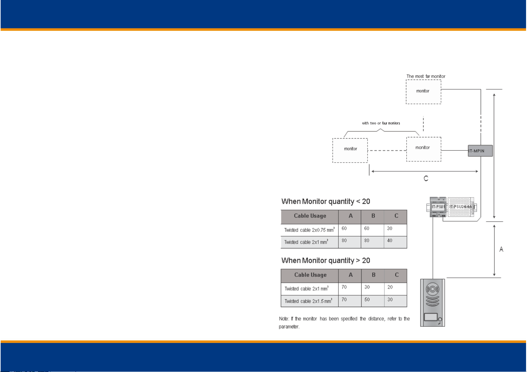
7. Cable Requirements
The maximum distance of the wiring is limited in the 2-wired system. Using different cables may
also affect the maximum distance which the system can reach.
Page 3
www.viscoo.eu
6.3 Notices
Name
Description
Usage
IT-PSU24-
4A
Power supply,85~260Vac input,24Vdc/3A
output,10 DIN modules
Connect with multi door stations
or multi monitors up to 2 or above)
IT-PSU24-
1A
Power supply,85~260Vac input,24Vdc/1A
output, for basic kit only,4 DIN modules
Connect with one door station and
one monitor(IT-IN35-X can be connected two)
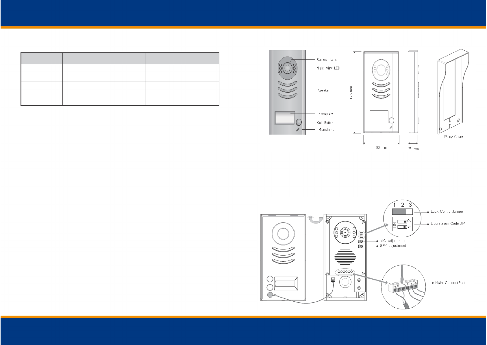
1. Parts and funcons
2. Terminal Descripons
Note: IT-OUT201/2 has 2 buons
www.viscoo.eu
Page 4
3. Specicaons
Lock Control Jumper: To select the lock type: see 5.2.1 , 5.2.2
Door station Code DIP: Total 4 door stations can be supported, see 6.1
Main Connect Port: To connect the bus line and the electronic locks.
B US: Connect to the bus line, no polarity.
PL: External lock power input, connect to the power positive (power +).
S1+, S2+: Lock power(+) output, to connect 2 locks.
S-: Lock power(-) output, connect to the power(-) input of locks (only when using the camera to
power the locks, if using the external power supply for the locks, the S- will not be connected).
Lock Power supply: 12Vdc, 300mA(Internal Power)
Power Consumption:
1W in standby, 12W in working
NO, COM dry contact: Max. 48V dc 1.5A
Unlocking time:
1 to 9 seconds, set by Monitor
Working temperature: -10ºC ~ 45ºC
4. Mounng
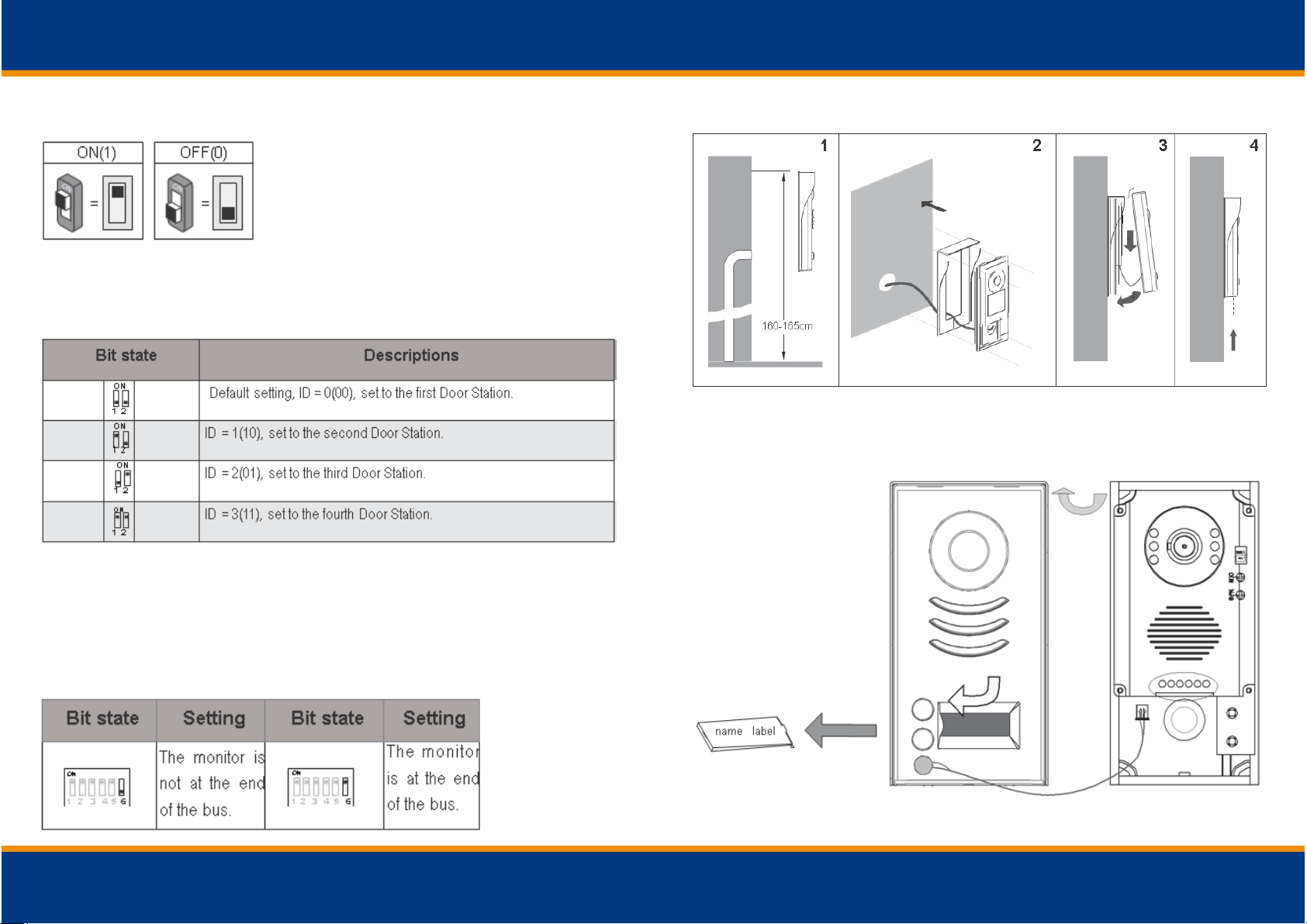
4.1 Mounting Without Rain Cover
www.viscoo.eu
www.viscoo.eu
Page 5
www.viscoo.eu
6. Setup
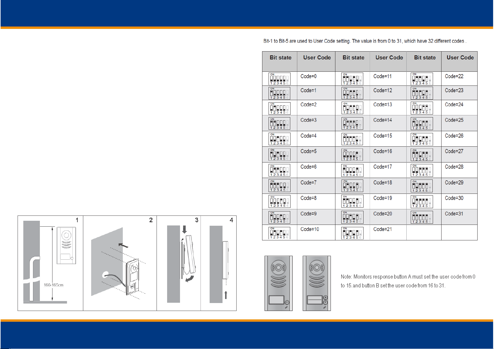
6.1 DIP Switch Settings of Door station
Total 2 bits on the DIP switches can be configured. The switches can be modified either before or after installation
6.2 DIP Switches Settings of Monitor
There are 6 bit switches in total. The DIP switches are used to configure the User Code for each
Monitor.
Bit-6 is line terminal switch, which have to be set to ON if the Monitor is in the end of the line
(bus), otherwise set to OFF.
4.2 Mounting With Rain Cover
4.3 Placing Name Label
Move the plastic cover away to open the transparent name label cover, insert a name paper, then put
the plastic cover back to the panel.
www.viscoo.eu
Page 6
5. System Wiring and Connecons
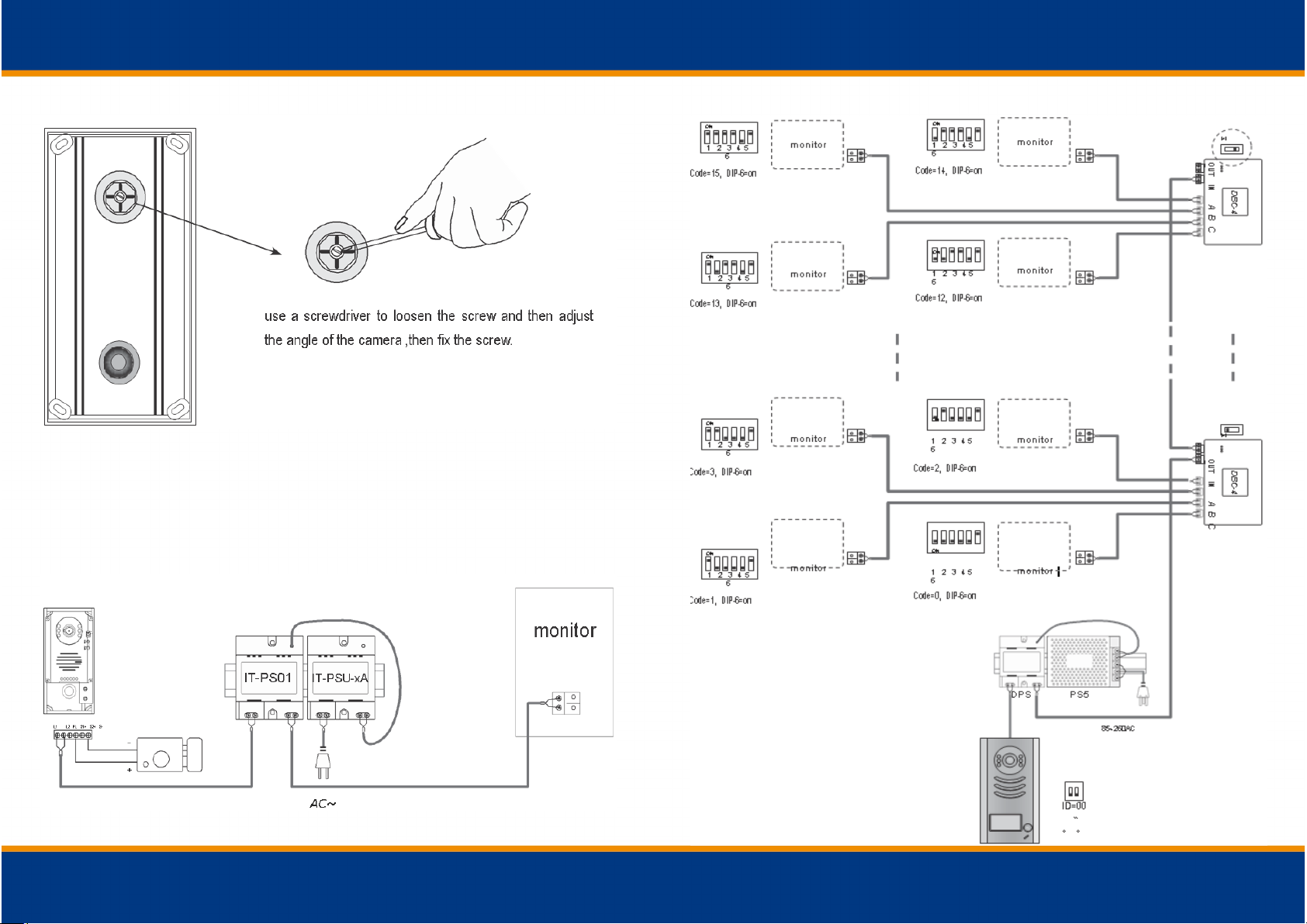
4.4 Adjusting Camera Angle
www.viscoo.eu
5.1 Basic Connection
www.viscoo.eu
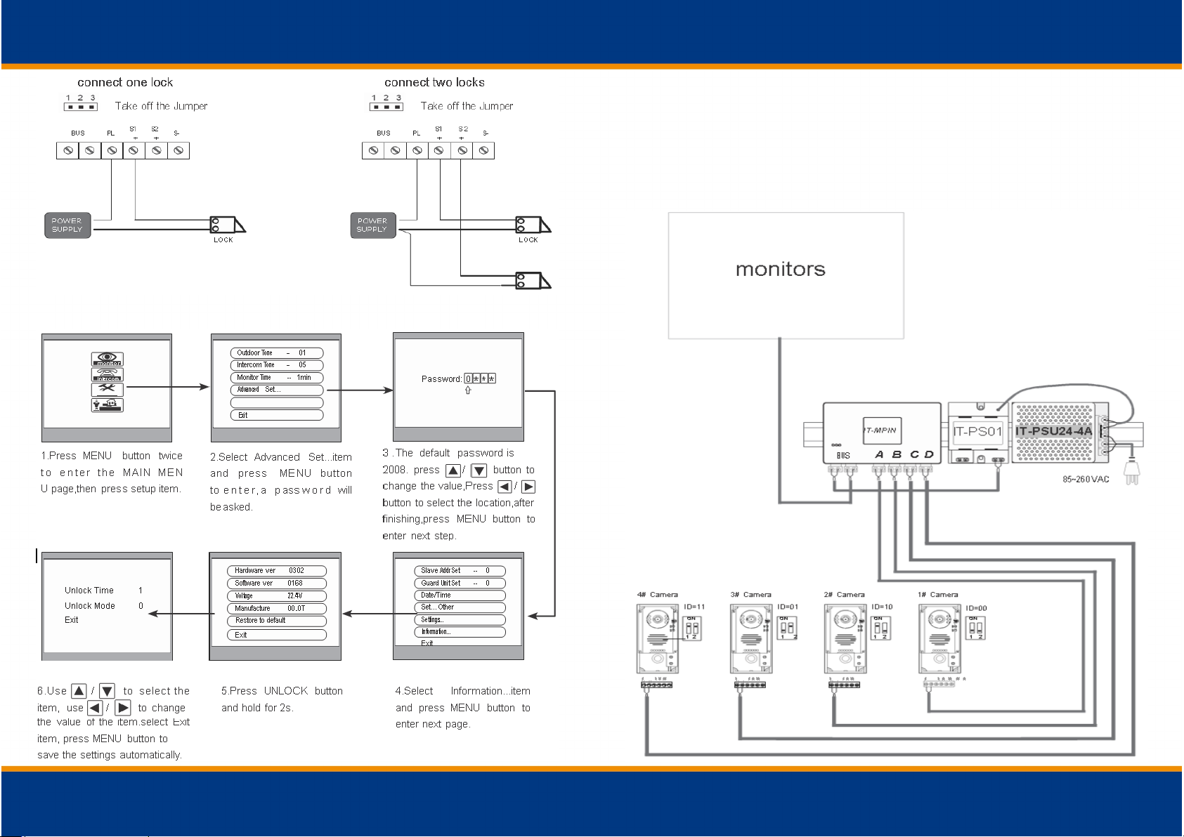
5.4.2 With IT-MPIN Wiring Mode
Page 7
www.viscoo.eu
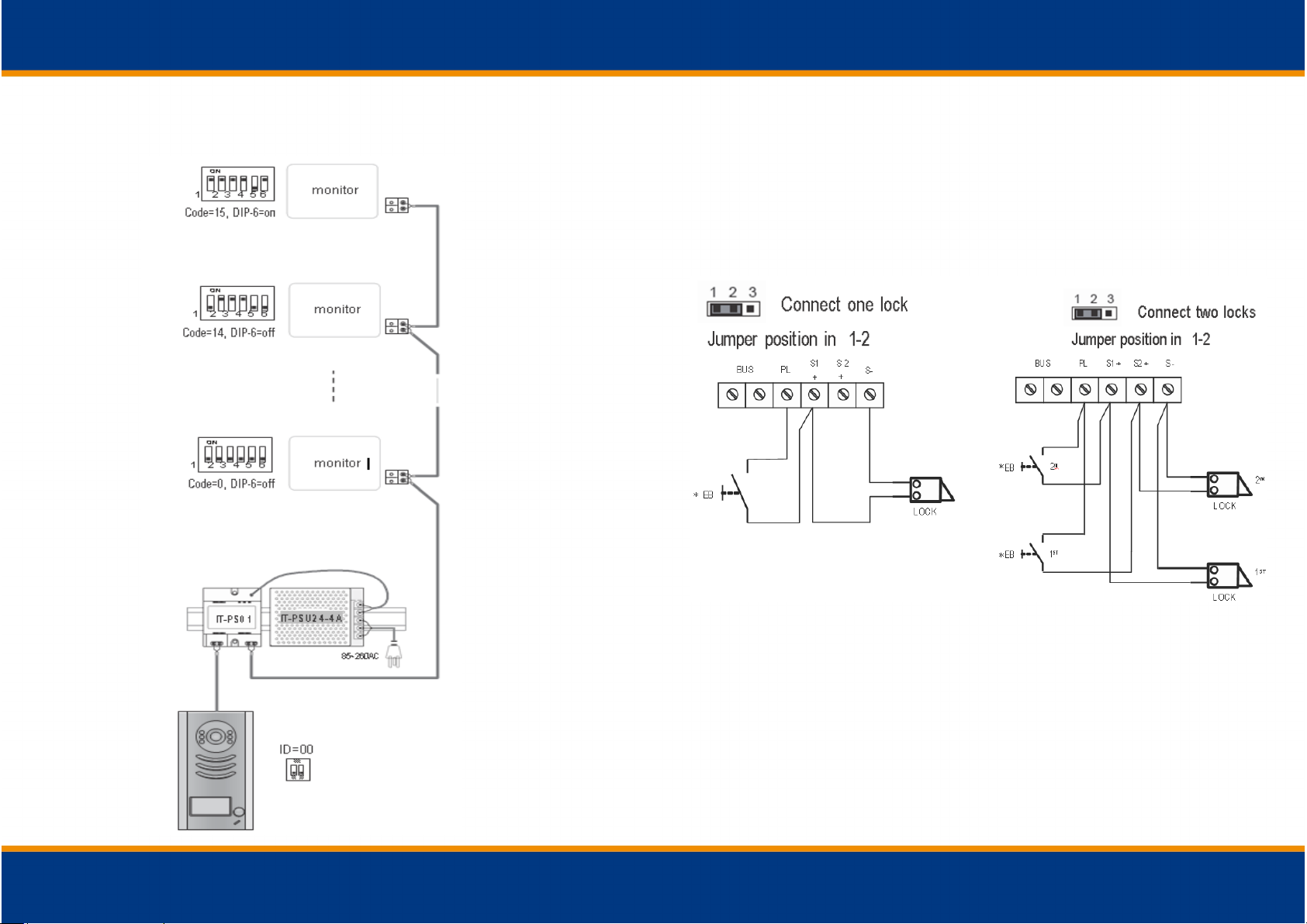
5.4 Multi Monitors Connection
5.4.1 Basic IN-OUT Wiring Mode
www.viscoo.eu
5.2.1 Door Lock Controlled with Internal Power
Note:
1. Electronic lock of Power-on-to-unlock type should be used.
2. The door lock is limited to 12V, and holding current must be less than 250mA.
3. The door lock control is not timed from Exit Button (EB).
4. The Unlock Mode Parameter of Monitor must be set to 0 (by default).
connect one lock connect two locks
5.2.2 Door Lock Controlled with Dry Contact
Note:
1. The external power supply must be used according to the lock.
2. The inside relay contact is restricted to AC or DC 24V/3A.
3. The jumper must be taken off before connecting.
4. Setup the Unlock Mode of Monitor for different lock types.
• Power-on-to-unlock type:Unlock Mode=0 (by default)
• Power-off-to-unlock type:Unlock Mode=1
Page 8
www.viscoo.eu
5.2.3 How to setup the unlock parameter in Monitor
www.viscoo.eu
Note:
1.must connect 201-1/201-2 correctly before setting.
2.the parameter will be saved in 201-1/201-2 automatically, so you need only set on one monitor.
3.the above settings are not fit for T-views series monitors. Please refer to T-views series monitor user
manual to how to set the unlock parameter.
5.3 Multi Door stations Connection
 Loading...