

Visart Technologies 10.4 PORTABLE TV with built-in multimedia Card Player Operation Instructions Manual

OPERATION INSTRUCTIONS
10.4 PORTABLE TV with built-in multimedia Card Player

Dear Customer:
Welcome to the splendid Portable TV. Now you may enjoy new visual experiences
and surprises from the marriage of advanced digital technology and new life philosophy.
To fully apply the product, please read the manual carefully and keep it for later reference.
Table of Contents
Check List
1. Introduction
2. Safety Precautions
3. Installation Instructions
3.1 Single Frame
3.2 Double Frame
4. Remote Control Guide
5. Setup Menu
5.1 SETUP MENU - MAIN PAGE
5.2 SETUP MENU - PHOTO
5.3 SETUP MENU - MUSIC
5.4 SETUP MENU - SLIDE SHOW
5.5 SETUP MENU - MOVIE
5.6 SETUP MENU - PREFERENCES PAGE
5.7 SETUP MENU - EXIT SETUP
6. OSD Setup Guide
6.1 AV Mode
6.1.1 VIDEO ADJUST
6.1.2 OSD ADJUST
6.1.3 INPUT SELECT
6.1.4 AUDIO
6.1.5 LANGUAGE SELECT
6.1.6 EXIT
6.2 TV Mode Settings
6.2.1 TV FUNCTION
6.2.2 TV MODE
7. TV Operation
7.1 AUTO CHANNEL SEARCH
7.2 CHANNEL SELECTION
7.3 DISPLAY CHANNEL
7.4 CHANNEL RECALL
AV Input/Output User Instruction
8.
9. Product
Specifications
1
1
1-4
1-3
3-4
4-6
6-11
6-7
7
8
8-9
9
9-11
11
11-15
11-13
11-12
12
12-13
13
13
13
14-15
14
15
15-16
15
15
16
16
16
17

Check List
When you open the box, make sure the following components are not missing.
1)Portable TV (1)
2) TVStand (1)
3) Remote Control (1)
4) AV Cable (1)
5) CATV Cable (1)
6) Headphone (1)
7) Power Supply (1)
8) Warranty Card (1)
9) User Manual (1)
If you have any questions, please contact the retailer.
Introduction
10.4 Portable TV supports:
JPEG picture file.
WMA, MP3 sound files.
MPEG1, MPEG2 video files.
Background sound playing
13 different picture playing Modes.
CF, SM, MS, MS PRO, SD, MMC, IBM MICRODRIVE seven types of memory cards.
AV Input/Output
TV
Remote control support.
Safety Precautions
Please be aware of the following precautions.
1.Handle it carefully. Place machine on a soft cloth or surface before installation in order to
prevent for scratches.
2.Spray a little of cleaner on soft cloth and wipe the panel.
3.Do not block the vent to prevent overheating.
4.Never disassemble or perform self-maintenance and repair, since opening or removing
cover plate may cause high-voltage electric shock or other dangers. Have a qualified
technician perform all product maintenance.
Installation Instructions
3.1 SINGLE FRAME
- 1 -
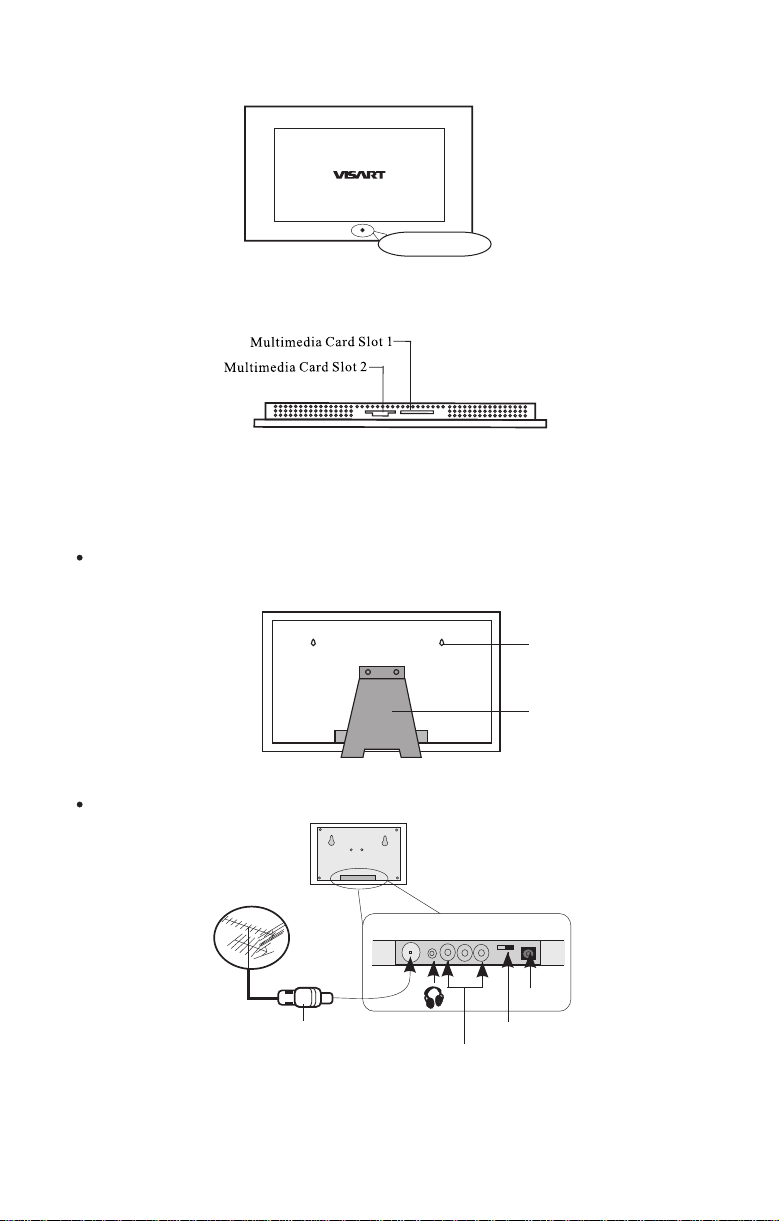
1. Front View(Fig. 1):
Remote Sensor
Fig. 1
2. Top View(Fig. 2):
Fig. 2
Two slots for CF, SM, MS, MS PRO, SD, MMC, IBM MICRODRIVE: 7 types of memory
cards supports.
3. Back View(Fig. 3):
Wall Hanging: can install onto the surface of a wall. Table Stand: use the stand to support
the Portable TV for weight support.
Hanging Hole
Input/output Introduction(Fig. 4):
TV
Stand
Fig. 3
DC 12V
Signal Switch
AV Connector
Fig. 4
- 2 -
lTV cable : Connect CATV cable or TV Antenna Cable to TV terminal.
l : Headphone Input (Sound export),can connect to headphone.
lAV input: Connects with AV cable and match the cable with the correct color input.
lSignal switch: switch AUDIO and VIDEO signal input/output.
lDC12V: Power input, install the power cord into the DC12V input.
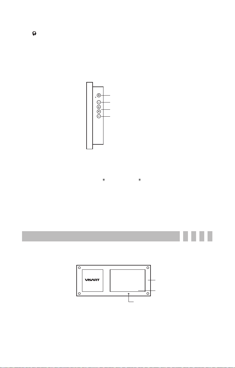
4. Button Instructions(Right-hand side)(Fig. 5):
Power
MODE
Add and Subtract
MENU
Fig. 5
Instruction:
lPower: on/off switch.
lMODE: Mode change, can switch TV、MEDIA PLAYER、AV.
lAdd、Subtract: Multifunction support
1.Before selecting any option, press Add and Subtrac buttons for volume control
2.Under TV, the buttons are for TV channel switch.
3.Under OSD menu, the buttons are for selecting menu options and adjustments.
lMENU: Highlight OSD menu.
3.2 DOUBLE FRAME
1. Front View(Fig. 6):
2. Side View(Fig.7):
Frame
LCD
Remote Control Sensor
Fig. 6
- 3 -
MENU
Add/Subract
MODE
Power
Fig. 7
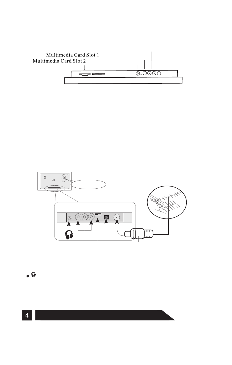
Two slots for CF, SM, MS, MS PRO, SD, MMC, IBM MICRODRIVE: 7 types of memory
cards supports.
Buttons instruction please go back to Single Frame Album instruction.
3.Digital Album display setup: (Review Single Frame Album for installation
instruction)
lWall setup:( hang horizontally)Able to hang on the wall
lTable setup: same as the Single Frame Album.
4. Back View(Fig.8):
Hanging Hole
AV Connector
:Headphone Input (Sound export), can connect to headphone.
lAV input: Connects with AV cable and match the cable with the correct color input.
lSignal Switch: switch AUDIO and VIDEO signal input/output.
lDC12V: Power input, install the power cord into the DC12V input.
lTV cable: Connect CATV cable or TV Antenna Cable to TV terminal.
DC 12V
Signal Switch
TV
Fig. 8
Remote Control Guide
- 4 -
 Loading...