

Page 1
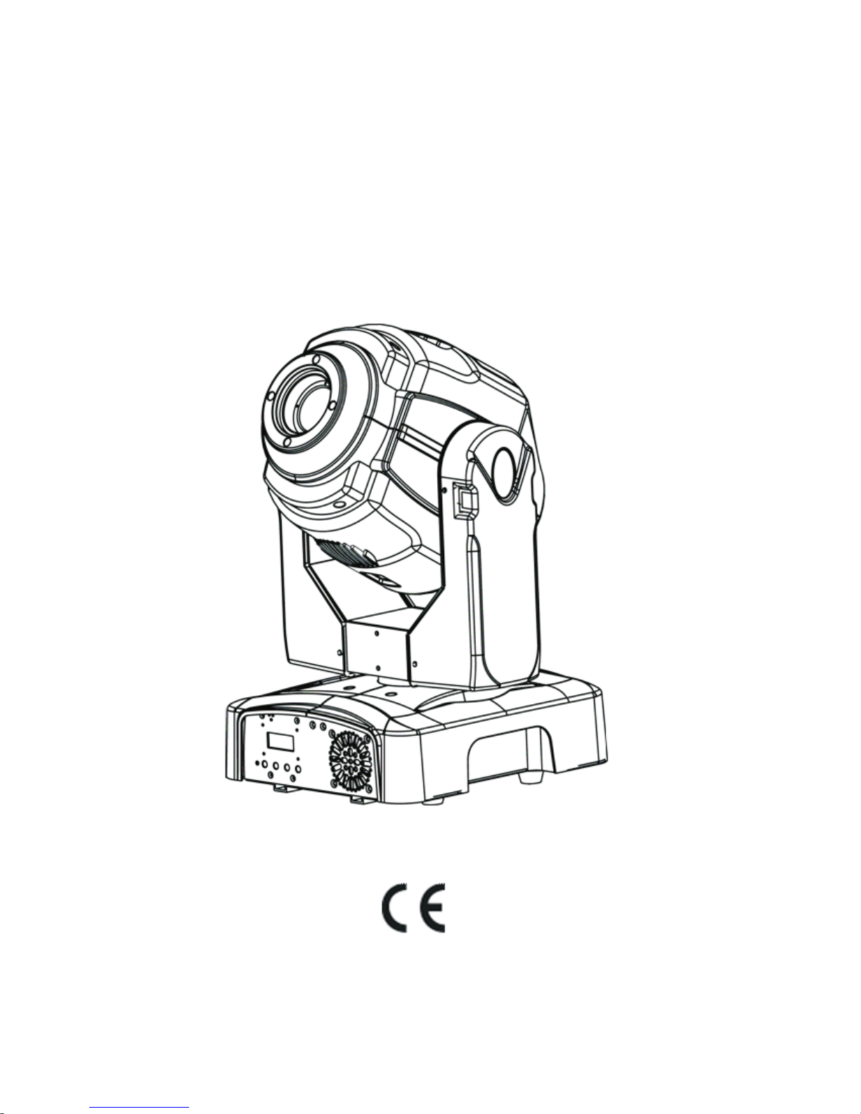
User Manual
LED MOVING HEAD 60W
Please Read over this Manual before Operating the Light Fixture
Page 2

1.BeforeyouBegin .......................................................................................1
What is Included ...................................................................................................................1
Unpacking Instructions ..........................................................................................................1
Text Conventions ...................................................................................................................1
Icons ...................................................................................................................................1
Safety Notes .........................................................................................................................2
Expected LED Lifespan .......................................................................................................... 2
2. Introduction ..............................................................................................3
Feature Description .....................................................................................................................3
Features.......................................................................................................................................3
Additional Features....................................................................................................................3
DMX Channel Summary ................................................................................................................3
Product Overview .........................................................................................................................4
3.Setup .........................................................................................................5
AC Power................................................................................................................................5
AC Plug ...............................................................................................................................5
Fuse Replacement................................................................................................................5
Gobo Replacement ................................................................................................................6
LED Replacement...................................................................................................................6
DMX Linking .........................................................................................................................6
DMX Modes ........................................................................................................................6
Master/Slave Linking .............................................................................................................6
Mounting .............................................................................................................................. 7
Orientation .........................................................................................................................7
Rigging ...............................................................................................................................7
4. Operation .................................................................................................8
Control Panel Description ......................................................................................................8
Control Options .................................................................................................................... 8
Programming ........................................................................................................................8
DMX Operation ..................................................................................................................8
Stand-alone Operation........................................................................................................8
Master/Slave Operation ......................................................................................................8
Display Mode .....................................................................................................................8
Software Version ................................................................................................................8
Keylock .............................................................................................................................9
Movement Inversion ...........................................................................................................9
Color Wheel Movement .......................................................................................................9
Edit Custom .......................................................................................................................9
Range Limitation.................................................................................................................10
Move-in Black .....................................................................................................................10
Reset Control.....................................................................................................................10
System Default ...................................................................................................................10
Menu Map ......................... ....... ...... ....................................................................................11
DMX Values ..........................................................................................................................12
ADVANCED........................................................................................................................12
ADVANCED (Cont.) ............................................................................................................13
BASIC ...............................................................................................................................13
BASIC (Cont.) ....................................................................................................................14
5. Technical Information...............................................................................15
General Maintenance ..................................................................................................................15
Troubleshooting Guide........... ...... ...... ...... .................................................................................16
Exploded View .............................................................................................................................17
Tableof Contents
Page 3

Parts List .............................................................................................................................18
Photometrics ........................................................................................................................18
Returns Procedure ...............................................................................................................19
Claims .................................................................................................................................19
Technical Specifications........................................................................................................ 20
6. Appendix................................................................................................... 21
DMX Primer ......................................................................................................................... 21
The Physical Medium............................................................................................................ 21
The Signals ......................................................................................................................... 21
The Functions ......................................................................................................................21
DMX Configuration ................................................................................................................21
Personalities ....................................................................................................................... 21
Starting Address .................................................................................................................. 21
Assigning Addresses ............................................................................................................22
DMX Universes ....................................................................................................................22
DMX Connectivity .................................................................................................................22
Fixture Location ...................................................................................................................22
Number of Fixtures ............................................................................................................... 22
DMX Data Cabling ................................................................................................................ 22
Making your Own DMX Cable................................................................................................. 22
DMX Cable Characteristics ....................................................................................................22
DMX Cable Connectors ........................................................................................................ 23
3-Pin to 5-Pin Conversion Chart ............................................................................................ 23
DMX Connection.................................................................................................................. 23
Master/Slave Linking ............................................................................................................. 24
Master/Slave Connection .....................................................................................................24
ID Addressing .......................................................................................................................25
Single Row Connection......................................................................................................... 25
Standard Block Connection .................................................................................................. 25
Repeated Row Block Connection .......................................................................................... 25
Other Effects .......................................................................................................................25
Sizing the Circuit Breakers .....................................................................................................26
Using the Spec Sticker..........................................................................................................26
Using the Watts/Volts Method................................................................................................ 26
Considering the Power Factor ............................................................................................... 26
Using the Volt Amps Method ..................................................................................................26
Selecting the Circuit Breaker ................................................................................................ 26
Page 4
1. Before you Begin
What is
Included
Unpacking
Instructions
Text
Conventions
Conve nt ion Meaning
1~512
50/60
[10]
Claims
<SET>
Settings
MENU > Settings
[1~10]
Yes/No
ON
“COLORado™ UM ™”
A range of values
A set of mutually exclusive values in the text
A DIP switch to be configured
A fixture function, a new term, a section or a chapter
The name of another publication or manual
A button to be pressed on the fixture's control pan
A menu option that can be selected but not modified
A sequence of menu options to be followed
A range of menu values of which one can be selected
A set of mutually exclusive menu options to choose
A value to be entered
Icons
Icons Meani ng
The te rm “ DMX” used throughout t his document refers t o the USITTD MX512-A
transmission protocol
• One LED Moving head Light
• One power cord with plug
• Two mounting brackets
• Quick Reference Guide
This icon indicates useful, although non-critical information.
This icon indicates important installation or configuration in
formation. Failure to comply with this information may prevent
the fixture from functioning correctly.
This icon indicates critical installation, configuration or operation
information. Failure to comply with this information may render
the fixture partially or completely inoperative, damage thirdparty equipment, or cause harm to the user.
Immediately upon receiving a fixture, carefully unpack the box. Check the box contents
to ensure that all parts are present and that they are in good condition. If any part
appears damaged from shipping, or if the box shows signs of mishandling, notify the
shipper immediately. In addition, retain the box and all the packing material for
inspection.
In any event, save the carton and all packing material because, in case that you have
to return the fixture to the factory, you will have to do so in its original box, with its
original packing. See the Claims section in the Technical Information chapter.
--1--
Page 5
Safety
Notes
Operation
Expected LED
Lifespan
Please read the following notes carefully because they include important
safety information about the installation, usage and maintenance of this product.
It is important to read all these notes before starting to work with this product.
There are no user serviceable parts inside the light. Any reference to servicing this unit
you may find from now on in this User Manual will only apply to properly C we certified
technicians. Do not o pen the housing or attempt any repairs unless you are one of them.
Please refer to all applicable local codes and regulations for proper installation
of the light.
Keep this manual for future consultation. If you sell the light to another user, make
sure that they also receive this manual.
Personal
Safety
Mounting
and Rigging
Power
and Wiring
Avoid direct eye exposure to the light source while the fixture is on.
Always disconnect the light from its power source before servicing.
Always connect the light to a grounded circuit to avoid the risk of electrocution.
This product is for indoor use only! To prevent risk of fire or shock, do not expose
this product to rain or moisture.
Make sure there are no flammable materials close to the fixture(s) while operating.
When hanging this fixture, always secure it to a fastening device using a safety
cable (not provided).
Always make sure that you are connecting the light to the proper voltage, as per the
specifications in this manual or on the product's sticker.
Never connect the light to a dimmer pack.
Make sure that the power cable is not cracked, crimped or damaged.
Never disconnect the fixture by pulling or tugging on the power cable.
The maximum ambient temperature (Ta) is 104 F (40 C). Do not operate the
fixture at a higher temperature.
In case of a serious operating problem, stop using this product immediately!
In t he unlikely e vent t hat your light may require ser vice, please contact our Technical
Support.
LEDs gradually decline in brightness over time, mostly because of heat. Packaged in
clusters, LEDs exhibit higher operating temperatures than in ideal or singular optimum
conditions. For this reason, using all color .LEDs at their fullest intensity significantly
reduces the LEDs' lifespan. Under normal conditions, this lifespan can be of 40,000 to
50,000 hours. If extending this lifespan expectancy is vital, lower the operational
temperature by improving ventilation and reducing the external temperature , as well
as limiting the overall projection intensity
--2--
Page 6
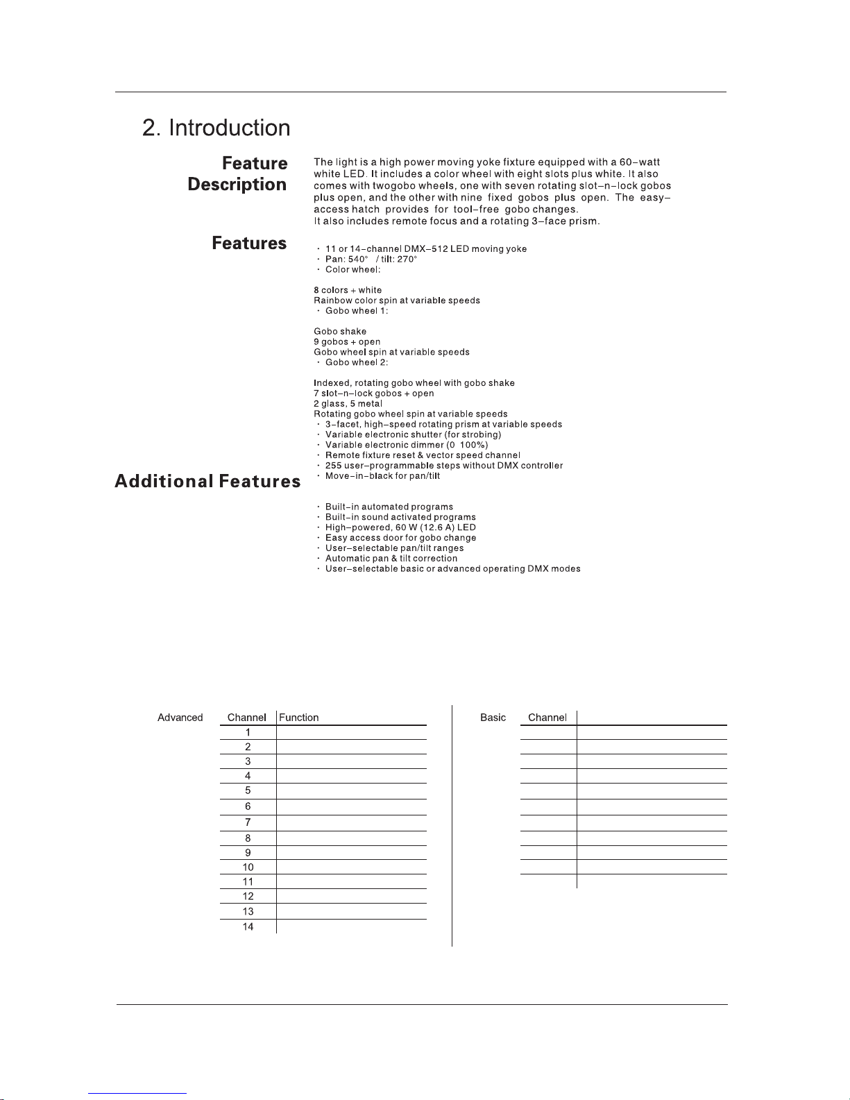
DMX Channel Summary
Function
Pan 1 Pan
Pan Fine 2 Tilt
Tilt 3 Color Wheel
Tilt Fine 4 Fixed Gobo Wheel (#1)
Pan / Tilt Speed
5 Rotating Gobo Wheel (#2)
Color Wheel
6 Gobo Rotation
Fixed Gobo Wheel (#1)
7 Rotating Prism
Rotating Gobo Wheel (#2) 8 Focus
Gobo Rotation 9 Dimmer
Rotating Prism 10 Strobe
Focus 11 Control
Dimmer
Strobe
Control
--3--
Page 7
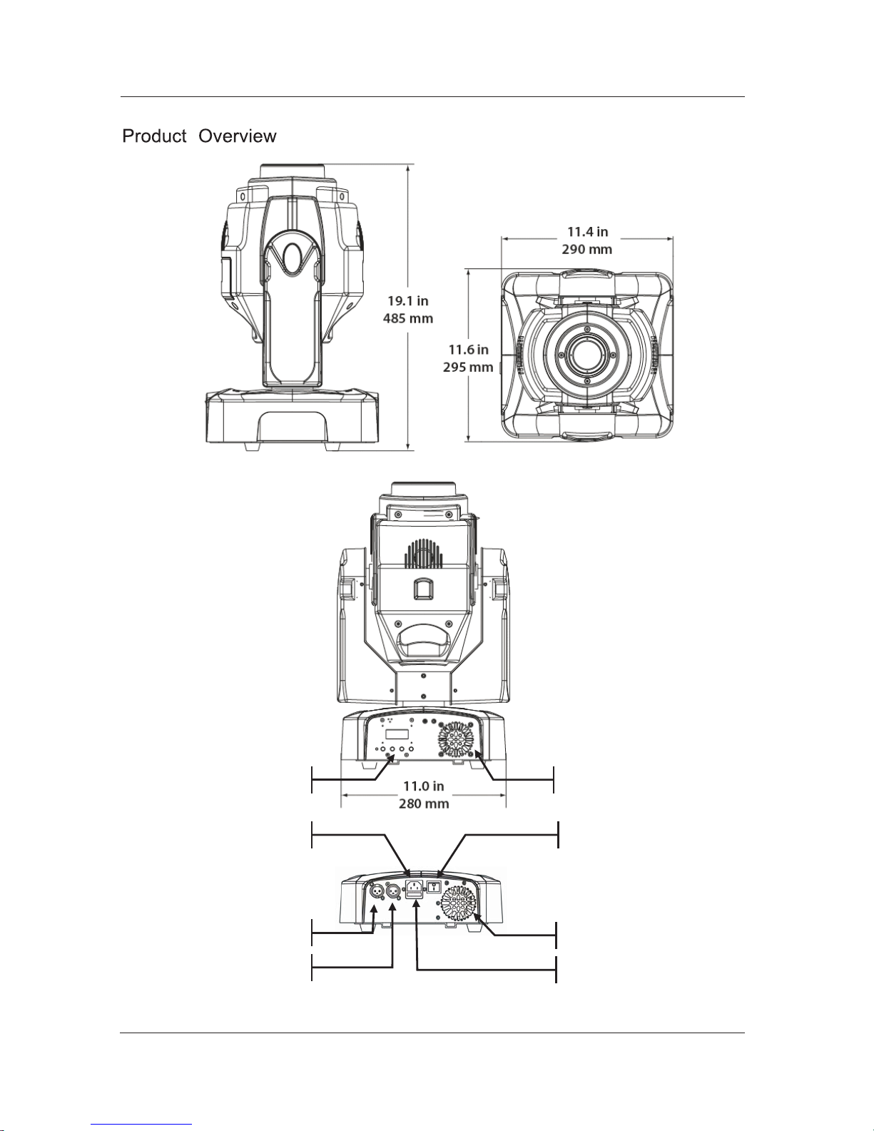
Product Dimensions Drawing Here
Base Fan
Fuse Holder
Control Panel
Base Fan
DMX Out
DMX In
Power Input On/Off Switch
--4--
Page 8
3. Setup
AC Power
The light has an auto-ranging power supply that can work with an input voltage range
of 100~240 VAC, 50/60 Hz.
Make sure that you are connecting this product to the proper voltage, as per the
specifications in this guide, the product's user manual or on the product's sticker.
AC Plug
AC Live Black Brown 1
AC Neutral White Blue 2
3
Fuse Replacement
Always connect the light to a protected circuit with an appropriate
electrical ground to avoid the risk of electrocution or fire.
To determine the power requirements for the light see the label affixed to the side of
the fixture. Alternatively, you may refer to the technical specifications chart in the
Technical Information chapter of this manual.
The listed current rating indicates the maximum current draw during normal operation.
Please refer to the Sizing the Circuit B reakers section in the Appendix chapter of this
manual.
Never c onnect the light to a r heostat ( variable r esistor) or dimmer circuit,
even if the rheostat or dimmer channel serves only as a 0 to 100% switch.
The light comes with a power input cord terminated with an IEC connector on one end
an Edison plug on the other end (US market). If the power cord that came with your fixture
has no plug or you need to change the Edison plug, use the tablebelow to wire the new plug
AC Ground Green/Yellow Green/Yellow
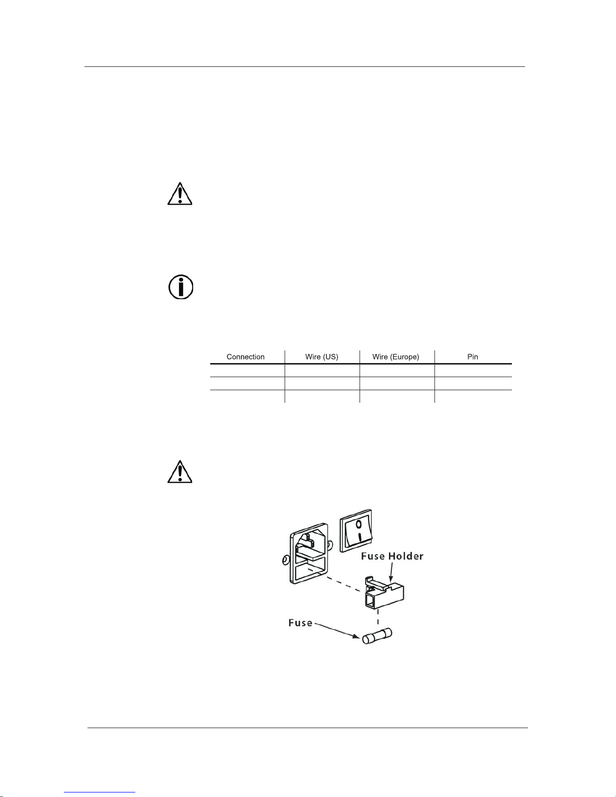
1) With a flat head screwdriver, wedge the fuse holder out of its housing and remove
the blown fuse from the holder.
2) Replace the blown fuse with a fuse of the exact same type and rating.
3) Insert the fuse holder back in its place, and reconnect power.
Make sure to disconnect the fixture's power cord before replacing a blown fuse,
and always replace it with a fuse of the same type and rating.
--5--
Page 9

Gobo
Replacement
LED
Replacement
1) Unlock the gobo cover and slide it away.
2) Take the target gobo out of the gobo wheel.
3) Install the new rotating gobo.
4) Slide and lock the gobo cover.
Make sure to disconnect the fixture's power cord before replacing the gobo.
1) Remove the head cover by loosening its screws.
2) Remove the fan cover, the head fan, the fan support and the heat sink in this order.
3) Disconnect and remove the LED.
Mount and connect the new LED.
5) Reverse steps "2" and "1".
Make sure to disconnect the fixture's power cord before replacing the LED.
DMX Linking
DMX Modes
Master/Slave
Linking
You may link the light to a DMX controller using a standard DMX serial connection. If using
other DMX compatible fixtures with the light, it is possible to control them individually with a
single DMX controller.
It is also possible to run several DMX compatible fixtures synchronized without a DMX
controller in a master/slave operating mode.
If you are not familiar with the DMX standard, please refer to the DMX Primer and
DMX Connectivity sections in the Appendix chapter of this manual.
The light uses the standard DMX data connection for its DMX modes, Advanced and
Basic. Refer to the Operation Instructions chapter to learn how to configure the light
to work in these modes. The DMX Values section will give you detailed information
regarding the above-mentioned DMX modes.
The Master/Slave mode allows a fixture (the master) running a preconfigured
program to control several other fixtures (the slaves) without requiring a DMX
controller. In this mode, all the slave fixtures will operate in
unison with the master fixture.
When in Master/Slave mode, the units link to each other using the standard DMX
connection.
If you are not familiar with the Master/Slave connectivity, please refer to the DMX
Primer and DMX Connectivity sections in the Appendix chapter of this manual.
The Operation chapter of this manual provides detailed instructions on how to
configure the Master and Slave units.
--6--
Page 10
Mounting
Orientation
Rigging
Procedure
Product
Mounting
Diagram
Read the safety notes at the beginning of this guide and follow their recommendations
before mounting this product.
Always mount this fixture in any safe position while making sure that there is adequate
room around it for ventilation.
Make sure to mount this fixture away from any flammable material as indicated in the
Safety Notes.
We recommends following the general guidelines below when mounting the light.
When selecting an installation location, consider ease of access to the fixture for
operation, programming adjustments and routine maintenance.
Never mount the fixture in places where rain, high humidity, extreme temperature
changes or restricted ventilationmay affect it.
Make sure that the location where you are mounting the fixture can support its
weight. Please see the Technical Specifications section of this manual for the
weight requirement of this fixture.
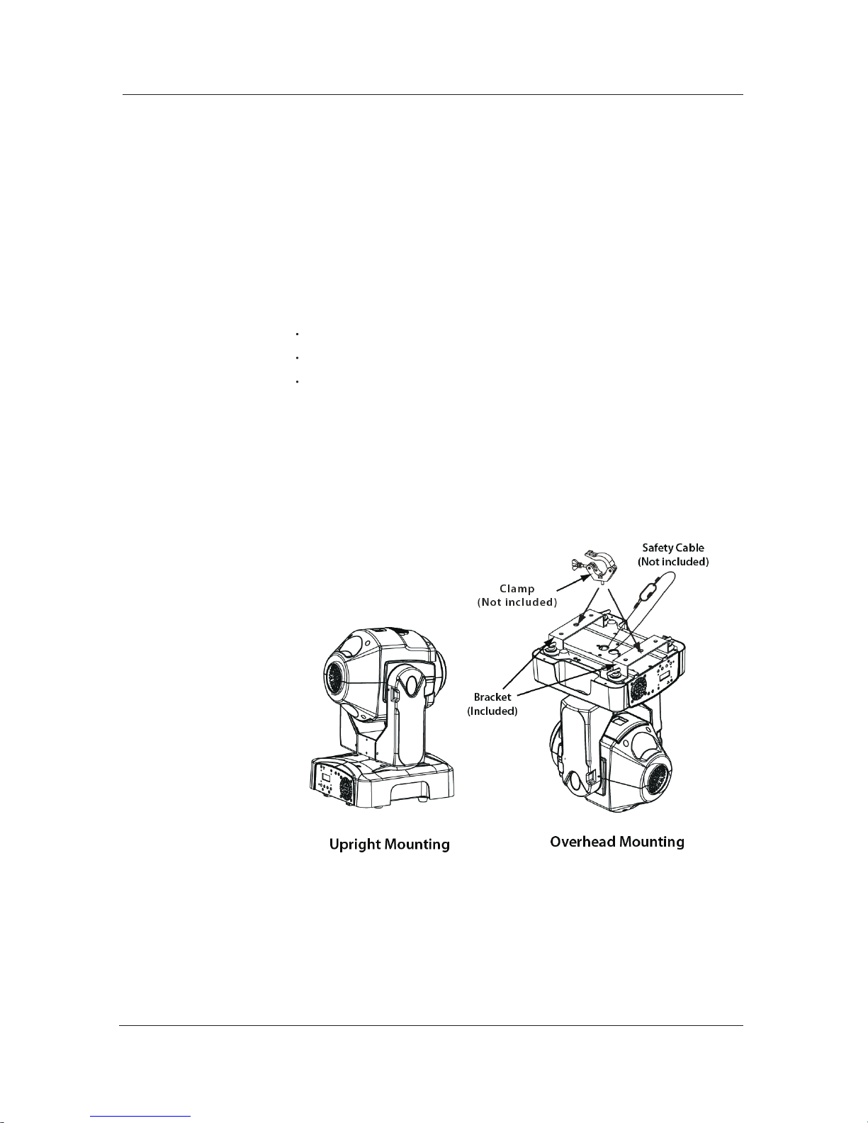
The light comes with two mounting brackets to which you can attach "C" or
"O" clamps. You must supply your own "C" or "O" clamps and make sure that they are
capable of supporting the weight of this fixture. You will have to use two mounting
points per fixture. In addition, you may mount this product on the floor or a platform,
provided it is stable and it can support the weight of the fixtures on it.
--7--
Page 11
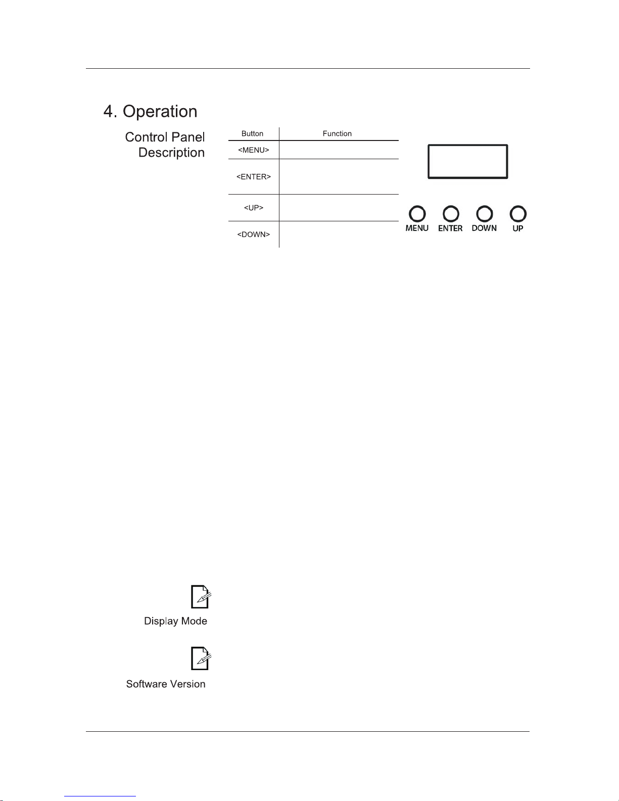
Exits from the current menu or
function
current
Enables the currently displayed
menu or sets the currently
selected value in to the
function
menu list and increases the
Navigates upwards through the
numeric value when in a function
Navigates downwards through
the menu list and decreases the
numeric value when in a function
Control Options
Programming
DMX Operation
Stand-alone
Operation
Master/Slave
Operation
You can set the light start address in the 001~512 DMX range. This allows for
the control of up to 36 fixtures in the 14-channel ADVANCED DMX mode and up
to 46 fixtures in the 11-channel BASIC DMX mode. The Q-Spot 260 LED does not
support ID Addressing.
Carry out all the programming procedures indicated below from the control panel.
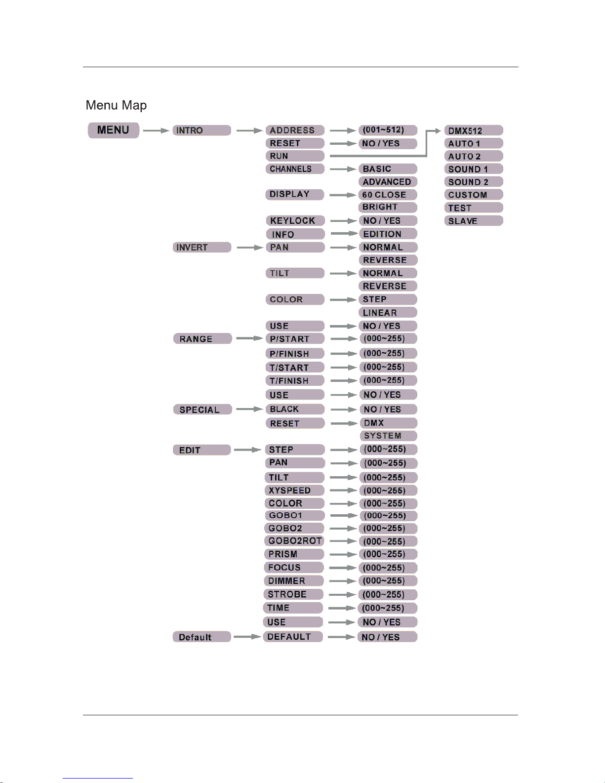
Refer to the Menu Map page to learn how the menu options relate to each other.
Use <ENTER> and <MENU> to change levels in the Menu M ap. This is equivalent
to move right and left respectively. Use <UP> and <DOWN> to move vertically
within theMenu Map options.
1) Select DMX operation
a) Go to MENU > INTRO > RUN
b) Select DMX512
2) Select a DMX mode
a) Go to MENU > INTRO > CHANNELS
b) Select BASIC or ADVANCED
3) Select the starting address
a) Go to MENU > INTRO > ADDRESS
b) Select a starting address, 001 ~ 498 (Advanced) or 001~501 (Basic)
1) Go to MENU > INTRO > RUN
2) Select a stand-alone operation mode (AUTO 1, AUTO 2, SOUND 1, SOUND 2,
CUSTOM or TEST)
1)Configure the Master fixture
a) Select a stand-alone mode, as indicated above
2)Configure the Slave fixtures
a) Go to MENU > INTRO > RUN
b) Select SLAVE
Of all the st and-alone operation modes i ndicated ab ove, o nly " CUSTOM" is
editable (see Edit Custom).
1) Go to MENU > INTRO > DISPLAY
2) Select a display mode (60 CLOSE or BRIGHT)
When in the "60 CLOSE" setting, the display backlight will turn off after 60 s.
When in the "BRIGHT" setting, the display backlight will stay on.
1)Go to MENU > INTRO > INFO
2)The display will show the installed software version.
--8--
Page 12

Keylock
Movement Inversion
Color Wheel
Movement
Edit Custom
1) Go to MENU > INTRO > KEYLOCK
2) Select YES or NO
When i n t he " YES" set ting, the u ser will h ave to en ter t he password after 30
seconds of control panel inactivity or each time he/she turns the fixture on.
The default (non-modifiable) password is < UP>, <DOWN>, < UP>, < DOWN> and
<ENTER>.
1) Go to MENU > INVERT > PAN
2) Select a movement mode (NORMAL or REVERSE)
3) Go to MENU > INVERT > TILT
4) Select a movement mode (NORMAL or REVERSE)
5) Go to MENU > INVERT > USE
6) Select YES to activate the new settings or NO to stop using them.
1) Go to MENU > INVERT > COLOR
2) Select a movement mode (STEP or LINEAR)
3) Go to MENU > INVERT > USE
4) Select YES to activate the new setting or NO to stop using it.
1)Go to MENU > EDIT > STEP
2) Select a programming step (000~255)
3) Go to MENU > EDIT > PAN
4) Select a pan value (000~255)
5) Go to MENU > EDIT > TILT
6) Select a tilt value (000~255)
7) Go to MENU > EDIT > XY SPEED
8) Select a tilt/pan movement speed (000~255)
9) Go to MENU > EDIT > COLOR
10) Select a color wheel position (000~255) as per the DMX Values table
11) Go to MENU > EDIT > GOBO 1
12) Select a fixed gobo (000~255) as per the DMX Values table
13) Go to MENU > EDIT > GOBO 2
14) Select a rotating gobo (000~255) as per the DMX Values table
15) Go to MENU > EDIT > GOBO 2 ROT
16) Select a rotating gobo mode (000~255) as per the DMX Values table
15) Go to MENU > EDIT > PRISM
16) Select a rotating prism mode (000~255) as per the DMX Values table
17) Go to MENU > EDIT > FOCUS
18) Select a focus position (000~255)
19) Go to MENU > EDIT > DIMMER
20) Select a dimmer setting (000~255)
21) Go to MENU > EDIT > STROBE
22) Select a strobe setting (000~255) as per the DMX Values table
23) Go to MENU > EDIT > TIME
24) Select the duration of this step (000~255)
25) Go to MENU > EDIT > USE
26) Select YES to save the settings for this step or NO to delete them.
27) Repeat steps "3" to "26" for the other steps
To r epeat the Custom s teps in a n e ndless loop mode, c onfigure the " TIME"
setting of the last step as "0".
--9--
Page 13

Range Limitation
Move-in Black
Reset Control
System Default
1)Go to MENU > RANGE > P/START
2)Select the starting point for the limited pan (000~255)
3)Go to MENU > RANGE > P/FINISH
4)Select the finishing point for the limited pan (000~255)
5)Go to MENU > RANGE > T/START
6)Select the starting point for the limited tilt (000~255)
7)Go to MENU > RANGE > T/FINISH
8)Select the finishing point for the limited tilt (000~255)
9)Go to MENU > RANGE > USE
10)Select YES to activate the new settings or NO to stop using them.
1) Go to MENU > SPECIAL > BLACK
2) Select YES to enable the 3 seconds delay or NO to make the blackout immediate.
1)Go to MENU > SPECIAL > RESET
2)Select DMX to enable the DMX controller to reset the fixture (Control function) or
NO to reset the fixture only from the control panel.
1)Go to MENU > DEFAULT > DEFAULT
2)Select YES to default the fixture to its original factory settings.
--10--
Page 14
--11--
Page 15

ADVANCED
Channel Function
000 255 0~540°
000 255 Fine movement control
000 255 0~270°
000 255 Fine movement control
000 255 Fast~Slow
000 016
017 033
034 050
051 067
068 084
085 101
102 118
119 135
136 152
153 255
White
Red
Yellow
Magenta
Green
Orange
Blue
Light blue
Light green
Rainbow or linear effect
000 009
010 019
020 029
030 039
040 049
050 059
060 069
070 079
080 089
090 099
100 114
115 129
130 144
145 159
160 174
175 189
190 204
205 219
220 234
235 255
No gobo
Gobo 1
Gobo 2
Gobo 3
Gobo 4
Gobo 5
Gobo 6
Gobo 7
Gobo 8
Gobo 9
Shaking gobo 9
Shaking gobo 8
Shaking gobo 7
Shaking gobo 6
Shaking gobo 5
Shaking gobo 4
Shaking gobo 3
Shaking gobo 2
Shaking gobo 1
Flow effect
000 009
010 019
020 029
030 039
040 049
050 059
060 069
070 079
080 099
100 119
120 139
140 159
160 179
180 199
200 219
220 255
No gobo
Gobo 1
Gobo 2
Gobo 3
Gobo 4
Gobo 5
Gobo 6
Gobo 7
Shaking gobo 7
Shaking gobo 6
Shaking gobo 5
Shaking gobo 4
Shaking gobo 3
Shaking gobo 2
Shaking gobo 1
Flow effect
000 060
061 158
159 255
Gobo indexing
CW rotation (Slow~Fast)
CCW rotation (Slow~Fast)
000
001 004
005 127
128 132
133 255
No function
Prism engaged (no rotation)
CCW rotation (
Slow~Fast
No function
CW rotation (
Slow~Fast)
000 255
000 255 Dark~Bright
(Continues on next page)
....
....
....
....
....
....
....
....
....
....
....
....
....
....
....
....
....
....
....
....
....
....
....
....
....
....
....
....
....
....
....
....
....
....
....
....
....
....
....
....
....
....
....
....
....
....
....
....
....
....
....
....
....
....
....
....
....
....
....
....
--12--
Page 16
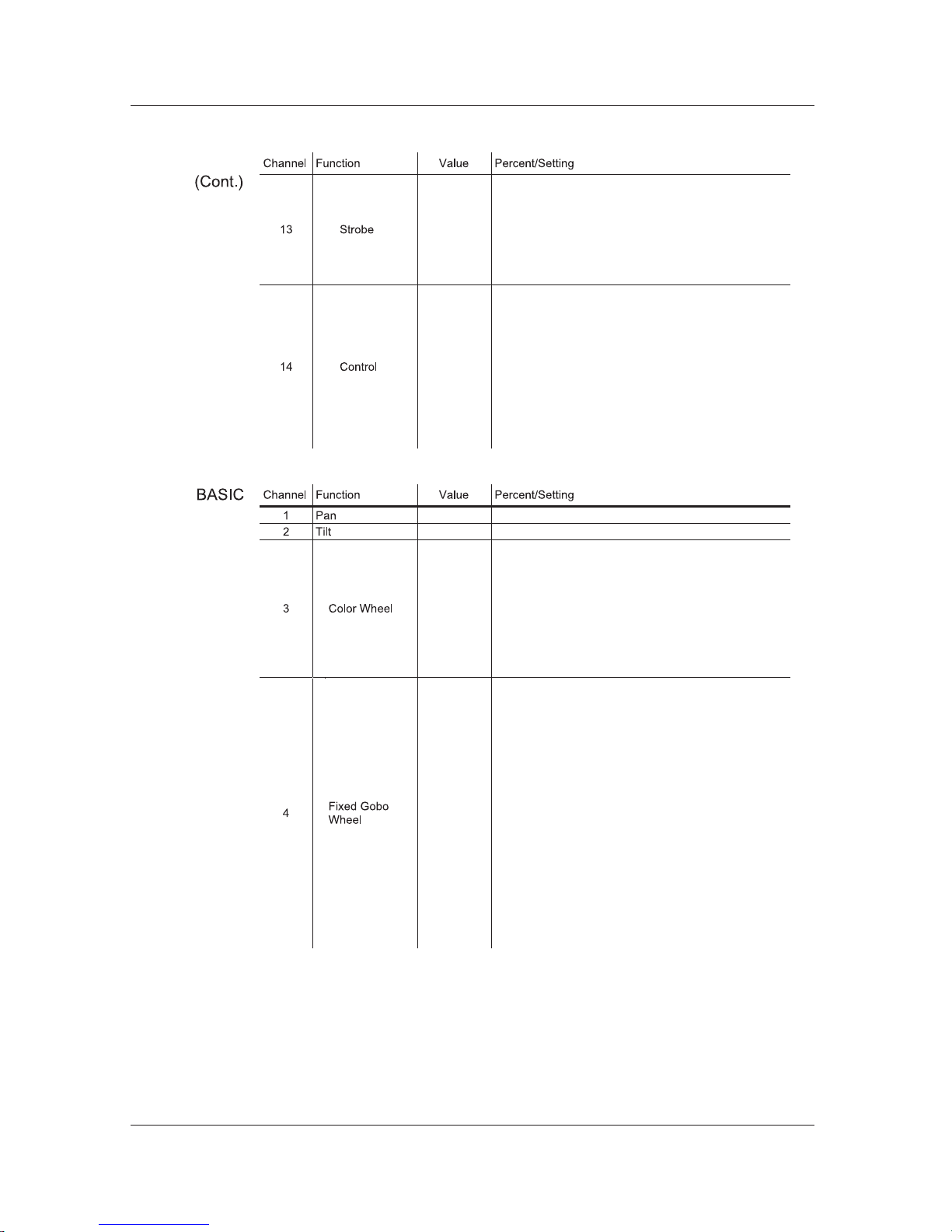
ADVANCED ADVANCED
000-----031
032-----063
064-----095
096-----127
128-----159
160-----191
192-----223
224 255
Close
Open
Strobe (
Slow~Fast)
Open
Pulse strobe effect (
Slow~Fast)
Open
Random strobe effect (
Slow~Fast)
Open
000----- 019
020-----039
040-----059
060-----079
080-----099
100-----119
120-----139
140-----159
160-----179
180-----199
200-----219
220----- 255
No function
Pan/tilt black activation (3 s delay)
Pan/tilt black deactivation (3 s delay)
Auto 1 (3 s delay)
Auto 2 (3 s delay)
Sound 1(3 s delay)
Sound 2(3 s delay)
Custom
Test (3 s delay)
No function
Reset (3 s delay)
No function
000----- 255 0~540°
000-----255 0~270°
000-----016
017-----033
034-----050
051-----067
068-----084
085-----101
102-----118
119-----135
136-----152
153----- 255
White
Red
Yellow
Magenta
Green
Orange
Blue
Light blue
Light green
Rainbow or linear effect
000-----009
010-----019
020-----029
030-----039
040-----049
050-----059
060-----069
070-----079
080-----089
090-----099
100-----114
115-----129
130-----144
145-----159
160-----174
175-----189
190-----204
205-----219
220-----234
235----- 255
No gobo
Gobo 1
Gobo 2
Gobo 3
Gobo 4
Gobo 5
Gobo 6
Gobo 7
Gobo 8
Gobo 9
Shaking gobo 9
Shaking gobo 8
Shaking gobo 7
Shaking gobo 6
Shaking gobo 5
Shaking gobo 4
Shaking gobo 3
Shaking gobo 2
Shaking gobo 1
Flow effect
-----
--13--
Page 17
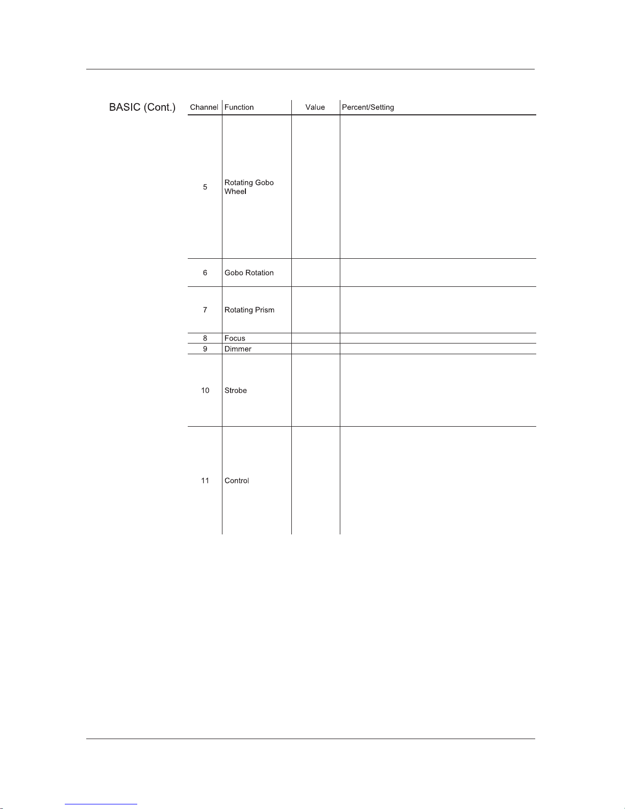
000----- 009
010-----019
020-----029
030-----039
040-----049
050-----059
060-----069
070-----079
080-----099
100-----119
120-----139
140-----159
160-----179
180-----199
200-----219
220-----255
No gobo
Gobo 1
Gobo 2
Gobo 3
Gobo 4
Gobo 5
Gobo 6
Gobo 7
Shaking gobo 7
Shaking gobo 6
Shaking gobo 5
Shaking gobo 4
Shaking gobo 3
Shaking gobo 2
Shaking gobo 1
Flow effect
000----- 060
061-----158
159 255
Gobo indexing
Clockwise rotating from slow to fast
Anti-clockwise rotating from slow to fast
000
001-----004
005-----127
128-----132
133----- 255
No function
Prism engaged (no rotation)
CCW rotation (
Slow~Fast)
No function
CW rotation (Slow~Fast)
000----- 255
000----- 255 Dark~Bright
000-----031
032-----063
064-----095
096-----127
128-----159
160-----191
192-----223
224----- 255
Close
Open
Strobe:
Slow~Fast
Open
Pulse strobe effect:
Slow~Fast
Open
Random strobe effect:
Slow~Fast
Open
000----- 019
020-----039
040-----059
060-----079
080-----099
100-----119
120-----139
140-----159
160-----179
180-----199
200-----219
220----- 255
No function
Pan/tilt black activated (activated after 3 s)
Pan/tilt black deactivated (activated after 3 s)
Auto 1 (activated after 3 s)
Auto 2 (activated after 3 s)
Sound 1(activated after 3 s)
Sound 2(activated after 3 s)
Custom
Test (activated after 3 s)
No function
Reset (activated after 3 s)
No function
----
--14--
Page 18
To clean a fixture, follow the below recommendations:
Always dry the external optics and glass surfaces carefully after cleaning them.
To maintain optimum performance and minimize wear, the user should clean the light
fixtures frequently. Usage and environment are contributing factors in determining the
cleaning frequency. As a rule, the user should clean the fixtures at least twice a
month. Dust build up reduces light output performance and can cause overheating.
This can lead to reduced light source life and increased mechanical wear.
We recommends cleaning the fixture's external optics with a soft cloth using normal
glass cleaning fluid.
Unplug the fixture from power.
Wait until the fixture is cold.
Use a vacuum (or dry compressed air) and a soft brush to remove dust collected on
the external vents and reachable internal components.
Clean all external optics and glass surfaces with a mild solution of glass cleaner or
isopropyl alcohol, and a soft, lint free cotton cloth or a lens cleaning tissue.
Apply the solution directly to the cloth or tissue and drag any dirt and grime to the
outside of the lens.
Gently polish the external glass surfaces until they are free of haze and lint.
When cleaning units with a movable mirror, you should keep the contact with the
mirror surface to a minimum to avoid scratching or damaging it.
If the fix ture has on e or compressed air. refrain from spinning them using
compressed air.
General
Maintenance
--15--
Page 19
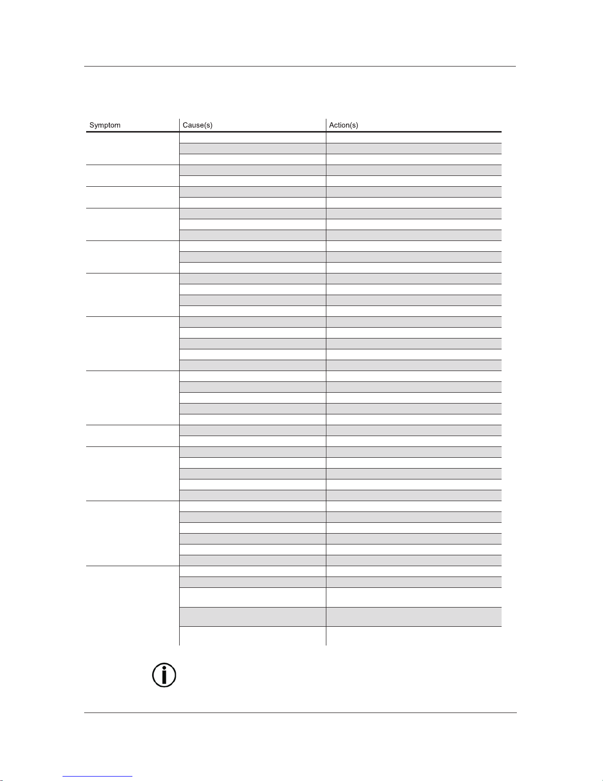
Troubleshooting Guide
Fixture is on
LED is off
LED connection problems Reconnect LED
Faulty LED Replace LED
Faulty LED driver Replace LED driver
Fixture is on
Head fan is off
Faulty head fan Replace head fan
Faulty LED driver Replace LED driver
Fixture is on
Base fan is off
Faulty base fan Replace base fan
Faulty power supply Replace power supply
Color wheel problem
Faulty color wheel motor Replace color wheel motor
Faulty sensor board Replace sensor board
Faulty X/Y control board
Replace X/Y control board
Replace X/Y control board
Replace X/Y control board
Prism problem
Faulty prism motor Replace prism motor
Faulty prism belt Replace prism belt
Faulty X/Y control board
Gobo wheel problem
Faulty gobo wheel motor Replace gobo wheel motor
Blocked gobo wheel Unblock
Faulty sensor board Replace sensor board
Faulty X/Y control board
Pan movement problem
Faulty pan motor Replace pan motor
Faulty pan belt Replace pan belt
Faulty magnetic sensor Replace magnetic sensor
Faulty optical sensor Replace optical sensor
Faulty X/Y control board
Tilt movement problem
Faulty tilt motor Replace tilt motor
Faulty tilt belt Replace tilt belt
Faulty magnetic sensor Replace magnetic sensor
Faulty optical sensor Replace optical sensor
Faulty X/Y control board
Circuit breaker/fuse keeps
tripping/blowing
Excessive circuit load Check total load placed on the electrical circuit
Short circuit along the power wires
Fixture does not power up
No power Check for power on power outlet
Loose or damaged power cord Check power cord
Blown fuse Replace fuse
Faulty On/Off switch Replace On/Off switch
Faulty internal power supply Replace internal power supply
Fixture does not respond
to DMX
Wrong DMX addressing Check control panel and unit addressing
Damaged DMX cables Check DMX cables
Wrong polarity on the controller Check polarity switch settings on the controller
Loose DMX cables Check cable connections
Faulty DMX interface
Faulty Display board
DMX signal problems
Non DMX cables Use only DMX compatible cables
Bouncing signals Install terminator as suggested
Long cable / low level signal
Install an optically coupled DMX splitter right after
the fixture with the strong signal
Too many fixtures
Install an optically coupled DMX splitter after unit
#32 or before
Interference from AC wires
Keep DMX cables separated from power cables or
fluorescent/black lights
If you still ex perience t echnical problems a fter tr ying the a bove s olutions, c ontact
our Technical Support.
Check for a short in the electrical wiring
Replace X/Y control board
Replace X/Y control board
Replace the display board
Replace the display board
--16--
Page 20
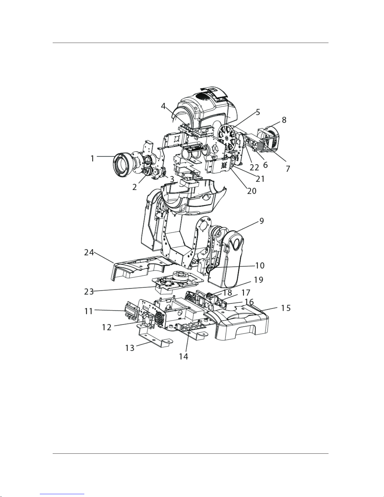
Exploded View
--17--
Page 21
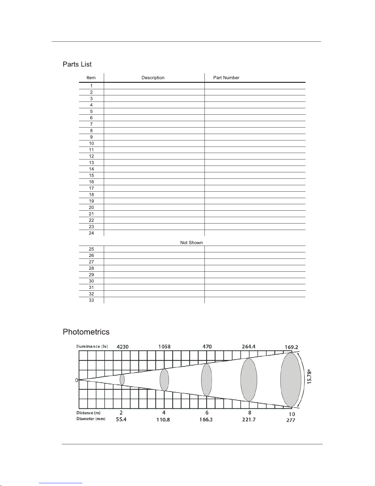
Front lens cover P114-Moving Head LFL
Prism P114- PRSM Moving Head
Prism motor P113-Moving Head LP
Motor driver board P188-Moving Head LED
Rotating gobo wheel P169-
Moving Head LED
LED board P222-Moving Head LED
Heat sink P222-Moving Head LHS
Moving head fan P131-MVNHD
Arm cover P300-Moving Head LA
Tilt motor P113- LEDT Moving Head
Display/main board P173- LED Moving Head
Base fan P131-24V15A
Mounting bracket P125-Moving Head LED
X/Y control board P175-Moving Head LED
Right base cover P300-Moving Head BB
3-pin XLR A socket P135-XLRA
3-pin XLR B socket P135-XLRB
IEC power input and fuse socket P190-Moving Head LED
On/Off switch P100-SWTCH
Fixed gobo wheel P169- LEDS Moving Head
Color wheel P149- LED Moving Head
Wheel motor P113-Moving Head LG
Pan motor P113-Moving Head LEDP
Left base cover P300-Moving Head BB
Power supply P142-Moving Head LED
Tilt belt P118-4863M
Pan belt P118-3M291
Rotating gobo wheel belt P118-Moving Head LRG
Fixed gobo wheel belt P118-Moving Head LSG
Color wheel belt P118-Moving Head LC
Prism belt P118-Moving Head LP
Fixed gobo wheel motor P113-Moving Head LSG
Color wheel motor P113-Moving Head LC
--18--
Page 22
Returns
Procedure
The user must send the merchandise prepaid, in the original box, and with its original
packing and accessories. We will not issue call tags.
Call us and request a Return Merchandise Authorization Number (RMA #) before
shipping the fixture. Be prepared to provide the model number, serial number and
a brief description of the cause for the return.
The user must clearly label the package with a Return Merchandise Authorization
Number (RMA #). We will refuse any product returned without an RMA #.
DO NO T write t he RMA # directly on t he b ox. Instead, write it o n a properly
affixed label.
Claims
For other issues such as missing components or parts, damage not related to shipping,
or concealed damage, the customer must make claims to us within seven (7) days of
receiving the merchandise.
Once you are given an RMA #, please include the following information on a piece of
paper inside the box:
• Your name
• Your address
• Your phone number
• The RMA #
• A brief description of the symptoms
Be sure to pack the fixture properly. Any shipping damage resulting from inadequate
packaging will be the customer's responsibility. As a suggestion, proper UPS packing
or double-boxing is always a safe method to use.
We reserves the right t o u se it s own discretion t o repair o r replace returned
product(s).
The carrier is responsible for any damage incurred during shipping. Therefore, if the
received merchandise appears to have damages caused during shipping, the customer
must submit the damage report and any related claims with the carrier, not ours.
The customer must submit the report upon reception of the damaged merchandise.
Failure to do so in a timely manner may invalidate the customer's claim
with the carrier.
--19--
Technical Specifications
Weight & Dimensions
Length................................................................................................................................. 11.4 in (290 mm)
Width .................................................................................................................................. 11.6 in (295 mm)
Height ................................................................................................................................. 19.1 in (485 mm)
Weight ................................................................................................................................... 30 l bs (13.6 kg)
Power
Auto-ranging ................................................................................................................. 100~ 240 V, 50/60 Hz
Power Consumption @ 120 V, 60 Hz .............................................. 150 W , 1.2 A (operation), 0.1 A (inrush)
Power Consumption @ 240 V, 50 Hz .............................................. 145 W , 0.6 A (operation), 0.1 A (inrush)
Light Source
LED ................................................................................................ ................................. 60 W, 50,000 hours
Quantity ........................................................................................................................................................ 1
Photo Optic
Luminance at 2 m ............................................................................................................................ 5,400 l ux
Beam angle .............................................................................................................................................. 15°
Control & Programming
Data input ...................................................................................................... locking 3-pin XLR male socket
Data output ................................................................................................. l ocking 3-pin XLR female socket
Data pin configuration .................................................................................... pi n 1 shield, pin 2 (-), pin 3 (+)
Protocols............................................................................................................................ USITT DMX512-A
DMX Channels ............................................................................................................................... 11 and 14
Page 23
6. Appendix
DMX Primer
The DMX protocol (USITT DMX512-A) is a networking protocol that enables a universal
DMX controller device to control the features of multiple DMX compatible fixtures,
whether par cans, wash lights, moving heads, follow spots, foggers , proprietary fixture
controllers, etc.
As any other networking protocol, the USITT DMX512-A describes the physical
medium, the signals and the functions they control.
The Physical
Medium
The DMX controller connects to it associated DMX compatible fixtures using a DMX
connection. This connection consists of a series of jumps between the DMX controller
and the various DMX compatible fixtures, also known as a daisy chain connection. In
this type of connection, the DATA OUT of one fixture or the DMX controller connects to
the DATA IN of the next fixture, and so on.
Each DMX fixture links to the previous and next DMX fixture or controller using a DMX
cable. This type of cable consists of a section of shielded, two-conductor twisted pair
cable with one 3-pin XLR male connector on one end and a 3-pin XLR female connector
on the other end. The XLR connectors pin-out is as follows: pin 1 is the Common (shield),
pin 2 is Signal Negative (S-) and pin 3 is Signal Positive (S+).
The Signals
The DMX signal stream is unidirectional, from the DMX controller to the DMX
compatible fixtures. These signals conform to the EIA-485 standard.
The Functions
Each DMX channel can have any unitary value in the 000~255 range. Each DMX
compatible fixture uses as many consecutive DMX channels as features the user can
control. The sequential numbers assigned to each DMX channel (1~512) are also
known as DMX addresses.
The function each DMX channel has and the results of assigning a value to each
depend on each controlled fixture. Some fixtures only use a single DMX channel,
while others may require 15 or more DMX channels to control all their functions.
Personalities
The DMX fixture configuration consists in determining how many channels each
fixture will need as well as assigning the corresponding DMX channels to each
fixture in order to size correctly the DMX controller.
Most DMX fixtures use multiple personalities, each of them requiring a different number
of channels, depending on the number of features it enables. The number of DMX
channels used by a fixture may vary from only one (usually the general dimmer control)
to 15 or more, as mentioned above.
When the job does not require using all the fixture's capabilities, the user can select a
more basic personality (less channels), thus allowing the DMX controller to
accommodate more DMX fixtures.
Starting
Address
The stream of DMX signals consists of 512 individual, sequential channels that form
a frame. The DMX controller constantly sends frames of DMX signals to the DMX
connection, even if not all of the 512 channels are in use. Because of this constant
transmission method, there can be only one DMX controller in a DMX connection.
Otherwise, the DMX signals sent by one controller would interfere with the signals
sent by the other controller(s).
For the DMX controller to control each DMX fixture, the user must first configure each
fixture's personality. This will determine the number of required channels to control the
fixture. Each channel will have a DMX address assigned to it. However, since assigning
a particular DMX address to each channel is impractical, the user will only need to
configure on each fixture the DMX address that corresponds to the fixture's Channel 1.
This is the fixture's starting address. The fixture will automatically assign the other
channels to the subsequent DMX addresses.
Once this assignment is complete, and based on the number of channels it uses, the
fixture will respond to the DMX signals sent to the range of DMX channels that begins
with the starting address.
For example, a fixture that uses six DMX channels and whose starting address is 100,
will accept DMX data sent by the DMX controller to channels 100, 101, 102, 103, 104,
and 105.
--21--
Page 24
DMX Configuration (Cont.)
Assigning
Addresses
DMX Universes
DMX
Connectivity
Fixture
Location
Number of
Fixtures
DMX Data
Cabling
Making your Own
DMX Cable
DMX Cable
Characteristics
The DMX data cable must have the following characteristics:
The user must carefully assign the starting addresses for each individual fixture to
avoid DMX channel overlapping. If the DMX channels do overlap, the affected
fixtures could operate erratically.
However, the user may decide to configure two or more similar fixtures with the same
personality and starting address. In this case, all the fixtures with the same starting
address will operate at unison.
A DMX universe is the set of DMX compatible fixtures connected to the same DMX
daisy chain, which are receiving DMX data from the same DMX controller using the
same set of 512 DMX channels.
Although in most cases an installation will consist of only one DMX universe, it
could be necessary to define two or more universes because of constrains
imposed by the distance or the number of features.
Most DMX controllers support only one universe, although some DMX controllers
may support two or more universes. Each universe will have its own separated
DMX daisy chain. A DMX compatible fixture can only be part of a single DMX universe.
Connecting the DMX fixtures to a DMX controller in small to medium installations is
usually a rather simple operation that requires a minimum of tools and some planning
(not including the actual fixture rigging and configuration).
However, in large installations it may be necessary to plan carefully the position and
cabling of each fixture to avoid unexpected problems.
The order in which the fixtures connect to the DMX controller is not important and
it has no effect on how a controller communicates to each fixture. However, the
user should always define a physical location for the fixtures that provides for the
easiest and most direct cabling to the controller and other fixtures.
When using a DMX controller, the combined number of channels required by all the
fixtures on the serial data link determines the number of fixtures the DMX controller
has to support. Conversely, the number of onboard sliders, page buttons and fixture
buttons limits the number of discrete DMX channels a DMX controller can support.
To comply with the E IA-485 standard, which is t he b ase f or t he US ITT
DMX512-A protocol, do not connect more than 32 fixtures without using a DMX
optically-isolated splitter. Doing otherwise ma y result i n deterioration of
the digital DMX signal.
You must use DMX compliant data cables to link two or more DMX compatible fixtures.
You may purchase our certified DMX cables directly from a dealer/distributor
or construct your own cable.
USITT recommends limiting the total length of t he DMX c able (from the first
fixture/controller to the last fixture) to 300~455 m (985~1,500 ft).
If you choose to create your own DMX cable, make sure to use data-grade cables
that can carry a high frequency signal and are less prone to electromagnetic
interference Use a Belden@9841 or equivalent cable, which meets the specifications
for EIA RS- 485 applications.
Do not us e standard microphone cables for D MX applications because they
cannot transmit DMX data reliably over long distances.
Type: shielded, 2-conductor twisted pair
Maximum capacitance between conductors: 30 pF/ft
Maximum capacitance between conductor and shield: 55 pF/ft
Maximum resistance: 20 ohms/1000 ft
Nominal impedance: 100~140 ohms
--22--
Page 25
DMX Connectivity (Cont.)
DMX Cable
Connectors
-
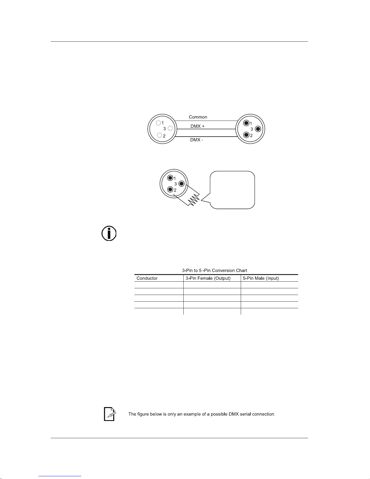
Ground/Shield Pin1 Pin 1
Negative (-) signal Pin 2 Pin 2
Positive (+) signal Pin 3 Pin 3
Not Used Pin 4
Not Used Pin 5
DMX Connection
The procedure below illustrates a possible DMX connection method.
To DMX Input
(Female)
DMX Connector Configuration
To DMX Output
(Male)
3-Pin to 5-Pin
Conversion Chart
Each DMX cable must have a male, 3-pin XLR connector on one end and a female, 3pin XLR connector on the other end.
To avoid signal transmission problems and interference, it is always advisable to
connect a DMX signal terminator, as seen below.
120 ohm, ¼W
resistor between
pin 2 (DMX -) and
pin 3 (DMX +) on
the output of the
last fixture.
Test all DMX cables with an ohmmeter to verify their correct polarity and to make
sure that there are no short-circuits between any of the pins, or between any pin
and ground.
If th e Common wire (shield) touched the chassis ground, a ground l oop could
form, which may cause the fixture to perform erratically.
If you use a DMX controller or fixture with a 5-pin DMX connector, you will need to use
a 5-pin to 3-pin adapter. The chart below details a proper cable conversion.
Make sure that the fixtures with which you are working can operate in DMX mode, not
in a proprietary connection mode. Refer to the fixtures' manual to learn how to enable
their respective DMX modes.
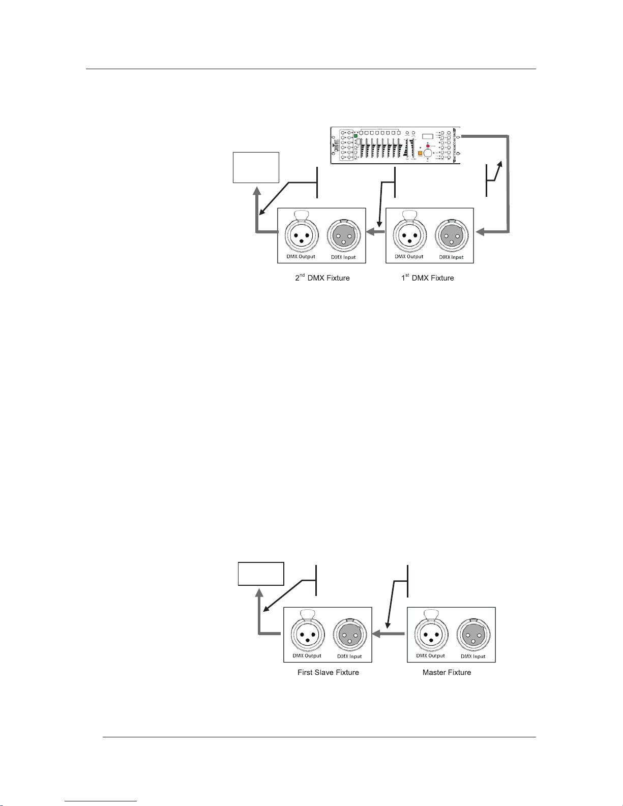
1) Connect the 3-pin, male connector of the first DMX cable to the DMX Output
connector (3-pin, female) of the DMX controller.
2) Connect the 3-pin, female connector of the first DMX cable coming from the
controller to the DMX Input connector (3-pin, male) of the first DMX fixture.
3) Connect the 3-pin, male connector of the second DMX cable to the DMX Output
connector (3-pin, female) of the first DMX fixture.
4) Connect the 3-pin, female connector of the second DMX cable coming from the first
DMX fixture to the DMX Input connector of the second DMX compatible fixture.
5) Continue linking the other DMX fixtures in the same way.
--23--
Page 26
DMX Connectivity (Cont.)
Generic
DMX Data
Connection
Diagram
Master/Slave
Linking
Master/Slave
Connection
The procedure below illustrates a possible connection method.
5) Continue linking the other slave fixtures in the same way.
Generic
Master/Slave
Connection
Diagram
DMX
Controlle
Other Slave
Fixtures
Other DMX
Compatible
Fixtures
Third
DMX
Cable
First
DMX
Cable
Second
DMX
Cable
The Master/Slave mode allows one fixture (the master) to run a preconfigured
program to control several other fixtures of the same model (the slaves) without
requiring a DMX controller. In this mode, all the slave fixtures will operate in unison
with the master fixture.
If a fixture supports the Master/Slave mode, it will have some sort of programming
function to configure it as master or slave. Those fixtures that only support DMX
mode cannot operate in Master/Slave mode.
Make sure the fixtures with which you are working are capable of operating in
Master/Slave mode. When working in Master/Slave mode, most fixtures use the DMX
data connection as well. The difference in this case is that there is no DMX controller
involved. Refer to the fixtures' manual to learn how to configure them to work in
Master/Slave mode.
1) Connect the 3-pin, male connector of the first DMX cable to the DMX Output
connector (3-pin, female) of the master fixture.
2) Connect the 3-pin, female connector of the first DMX cable coming from the master
fixture to the DMX Input connector (3-pin, male) of the first slave fixture.
3) Connect the 3-pin, male connector of the second DMX cable to the DMX Output
connector (3-pin, female) of the first slave fixture.
4) Connect the 3-pin, female connector of the second DMX cable coming from the
first slave fixture to the DMX Input connector (3-pin, male) of the second slave
fixture.
6) Follow the steps in fixtures' manual to configure the fixtures as master and slaves.
Second
DMX
Cable
First
DMX
Cable
--24--
Page 27
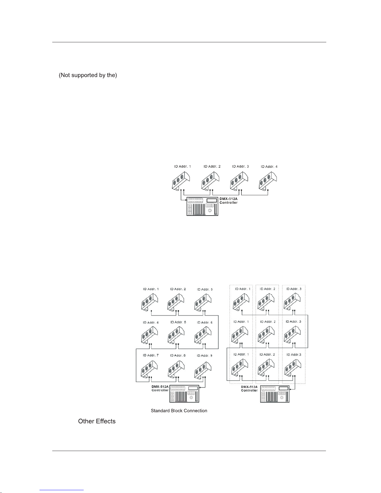
ID Addressing
Single Row
Connection
Single Row ID Addressing
Diagram
Standard Block
Connection
Repeated Row
Block Connection
ID Addressing is a sub-addressing method by which each fixture, apart from its starting
address, can also have an "ID" address in the 1~66 range. This allows users to multiply
the number of fixtures they can control with a single DMX controller.
Many fixtures have at least one DMX personality or mode that enables ID addressing.
In this case, one of the channels of such DMX mode is in charge of selecting an ID
address. When using ID addressing, setting the value of the ID addressing channel to
"0" allows for the simultaneous control of all the fixtures with the same starting address,
regardless of their particular ID address.
ID addressing is also a tool for creating special lighting effects by having several fixtures
sharing the same starting DMX address and ID address, as indicated below.
The figure below shows a simple DMX layout that uses four fixtures, all with the same
DMX address and a unique ID address for each fixture. This allows the user to control
simultaneously the whole group of units at that DMX address by setting the ID
Addressing channel to 0. Similarly, the user can control each fixture at that DMX
address independently by first selecting the DMX address and then using the ID
Addressing channel to locate the target ID address.
In the Standard Block connection, the fixtures appear in repeated rows of the same
length to form a block. For instance, three rows of fixtures with three fixtures per row
to form a 3 x 3 block. Each of the fixtures has unique, sequential ascending ID
addresses for the controller to control each fixture individually.
In this type of connection, the fixtures appear in repeated rows or columns of the same
length to form a block. For instance, there may be three columns of fixtures with three
fixtures per column to form a 3 x 3 block. In this case, the fixtures form groups, each
with its own sequential ascending ID addresses. This way, the controller will control
each group of fixtures individually.
Repeated Block Connection
For other types of effects, you may group the fixtures in diagonal lines or place them in
random positions within a single block.
--25--
Page 28

Sizing the
Circuit
Breakers
Using the
Spec Sticker
Using the
Watts/Volts Method
Considering the
Power Factor
2 A / 0.7 = 2.8571 A
Using the
Volt Amps Method
360 VA / 120 V = 3 A
Selecting the
Circuit Breaker
22 A * 1.25 = 27.5 A
Calculating the total current drawn by the fixtures connected to a particular circuit
is not complicated if the installer has the right information at hand and knows how
to interpret it.
With the fixture's current draw information, the installer can calculate and select the
right circuit breaker size (rating) to which they can connect a group of fixtures.
Our fixtures come with a sticker that indicates the current they consume in a
circuit at the specified voltage. This greatly simplifies calculating the total
current drawn.
For instance, if the sticker on the fixture indicates, "0.1 A @ 115 VAC, 60 Hz" and the
installer is connecting 12 of them on the same 115 VAC circuit, to determine the total
current required by the fixtures it would be enough to do this simple calculation:
0.1 A x 12 = 1.2 A
Some installers may prefer to determine the current drawn by the fixture by dividing
its power consumption, indicated in watts (W), by the voltage (V) on the circuit. As
an example, assuming that a certain fixture consumes 240 W and it is connected to
a 120 VAC circuit, the current it draws would be:
240W / 120 V 2A
The above method is accurate only with fixtures whose power factor (PF) is equal,
or very close, to "1." Otherwise, the calculated current may be too low with respect
to the actual current drawn by the fixture.
In fact, as the PF decreases, the difference between the current calculated using
the watts/volts method and the actual current increases.
Therefore, for fixtures with a PF below "0.9," the installer must always consider the
fixture's PF when using the watts figure to calculate the current it draws.
For the above example, if the published fixture's PF were "0.7," the resulting drawn
current would be as follows:
This is approximately equal )( to 2.86 A, 2.9 A, or even 3 A, depending on the
installer's desire for accuracy. In other words, the actual current ended up being
close to 50% higher than originally calculated.
If the fixture's sticker indicates the power consumption in "volt amps" (VA), the
calculation of the drawn current is simply the result of dividing the amount in VA by
the voltage on the circuit (V). For a fixture with a consumption of 360 VA, the
calculation would be as follows:
Note that when the power consumption is in VA, the fixture's PF is never part of the
current draw calculation.
The National Electric Code (NEC) determines that circuit breakers should handle
80% of their rated capacity for continuous loads (those being on for three or more
hours) and 100% for intermittent loads. For safety reasons, We recommends
assuming that all loads are continuous.
After calculating the total current the fixtures connected to a particular circuit will
draw, the installer must consider the 80% rule indicated above. For a total current
of 22 A, the calculation is as follows:
The installer should use a 30 A CB because the immediately lower CB rating, 25 A,
would not be enough for this load.
--26--
 Loading...