

VisAccess VXS-10 Installation Instructions Manual
VXS
VXS-10
VXSVXS
-10
-10-10
Single-Door Proximity Access Control System
1111. INTRODUCTION
. INTRODUCTION
. INTRODUCTION. INTRODUCTION
The VisAccess VXS-10 is an electronic access control system
designed for a single access point, such as a main door in an
apartment building or individual office doors. The system control
unit relay activates a lock or electromagnetic strike (EMS), when
a valid proximity key (tag or card) is presented to the reader
located outside the protected area.
The use of a proximity (non-contact) key makes the installation of
the VXS-10 system an attractive possibility in harsh environments
and in places with poor lighting conditions. The proximity keys are
totally sealed and are wear resistant. The reader reads the key’s
ID, whenever the key is presented.
A second proximity reader may be connected to the VXS-10 to
control both sides of a door. An optional magnetic stripe card
reader may be connected instead of a proximity reader.
The separate weatherproof readers give added security and
flexibility allowing outdoor or indoor installation.
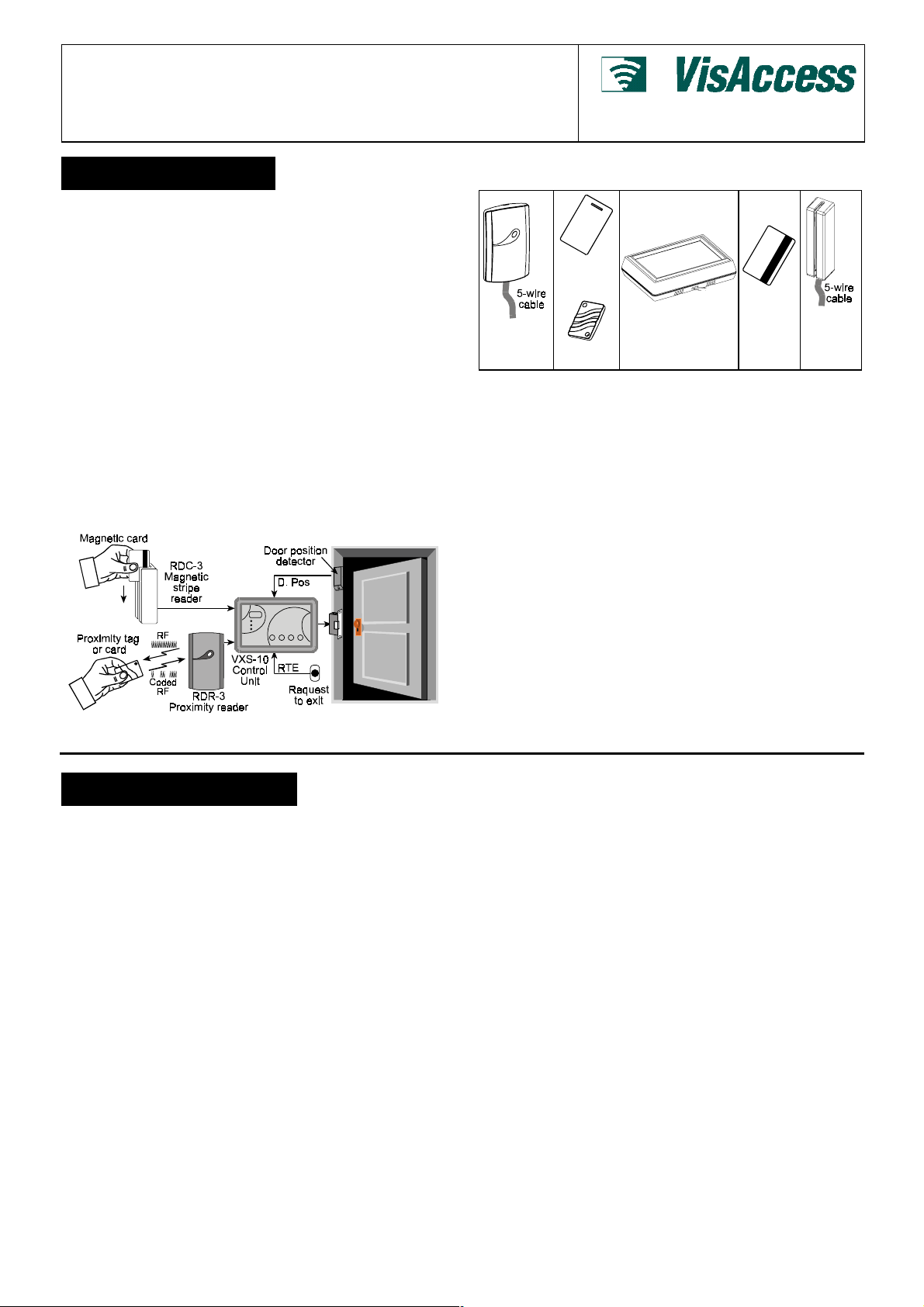
The VXS-10 control unit (see figure 1) includes a 3-digit display, 3
visual indicators (LEDs) and 4 buttons. An internal proximity
reader located in the upper right corner of the control panel
allows fast and easy programming of access keys. The buttons
are used for entering the password and for programming the unit.
Figure 1 - System Functional Presentation
The VXS-10 has a memory capacity of 300 keys. Adding keys
simply involves presenting new keys to the controller while the
system is in ADD mode.
The user can delete keys in the DELETE mode by presenting
them to the reader or, if a tag/card is not available, by typing in its
number (the same one that appears when adding the key).
The VXS-10 kit includes:
• VXS-10 controller
• RDR-3 proximity reader with 1m (3 ft) 5-wire cable
• Installation instructions
• User Guide
• Control unit base template, for wall installation
Additional tools and equipment that may be needed:
• Proximity tags or cards (ordered separately)
• Power supply for the controller - 12V AC/DC
• Electromagnetic strike (EMS) unit
• Request-to-exit push button or PIR, if “request to exit” option is
RDR-3
Proximity
Reader
required.
Installation Instructions
CRD-1
Prox. Card
VXS-10
Control Unit
TAG-1
Prox. Tag
Figure 2 - System Components
CRD-1M
Magnetic
Stripe
Card
RDC-3
Magnetic
Stripe
Reader
2222. SPECIFICATIONS
. SPECIFICATIONS
. SPECIFICATIONS. SPECIFICATIONS
VXS-10 CONTROLLER
Power Input: 9-12V AC/DC
Max Current Consumption: 150 mA (excluding EMS current)
Memory Capacity: 300 tags/cards
Output Relay Contact Rating: 1A Max. continuous current
Display: 3 x 7 segments and 3 LEDs
Operating Temperatures: 0°C to 50°C (32°F to 122°F)
Dimensions (L x W x D): 150 x 105 x 35 mm (5-7/8 x 4-1/8 x 1-3/8 in.)
Color: Dark brown
RDR-3 EXTERNAL READER
Indicators: Tricolor LED (Green, Red, Amber)
Tag Reading Range: 50-100 mm (2-4 in.)
Frequency: 125 KHz
Tag Code Possibilities: 10
Dimensions (L x W x D): 116 x 70 x 16.8 mm (4-1/2 x 2-3/4 x 5/8 in.)
Weight: 121.5 g (4.3 oz)
Operating Temperatures: -20°C to 50°C (-4°F to 122°F)
Cable (to VXS-10 control unit) maximum length: <10 meters
Color: Dark brown
RDC-3 MAGNETIC STRIPE READER (optional)
Output Type: Open collector, 12V
Communication Signals: Clock and data
12
possible combinations
DE6270 1
3333. INSTALLATION
. INSTALLATION
. INSTALLATION. INSTALLATION
NOTE: The installation must comply with local fire, health and
safety regulations.
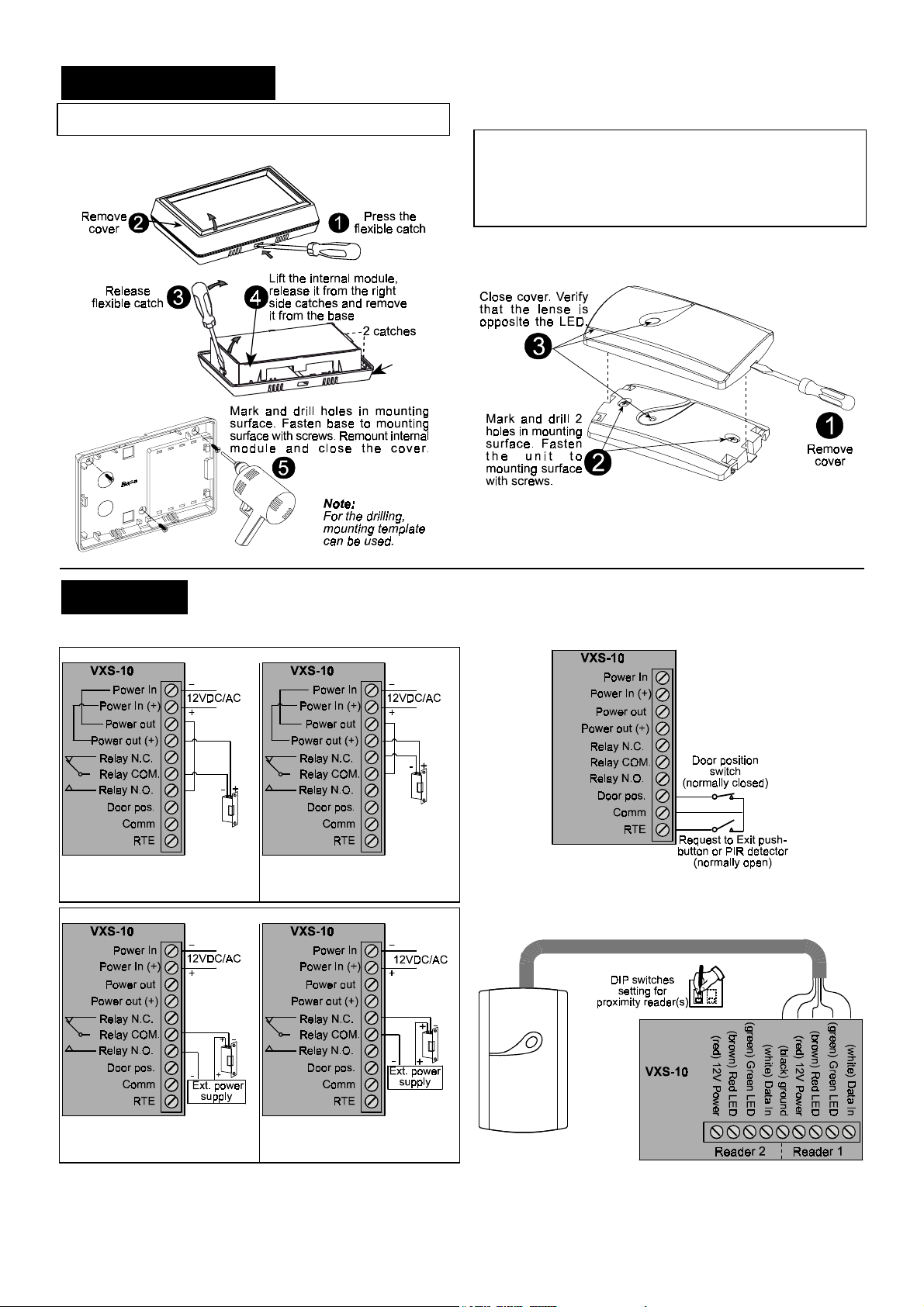
3.1 Controller Unit Installation
3.2 Proximity Reader Installation
Caution: Do not install the RDR-3 on a metal surface or on a
metal door frame, since this decreases the key reading range
significantly. If you have to install the reader on a metal surface,
use a spacer plate so that the reader will be at least 1 cm (3/8 in.)
away from the metal. You may use RDR-BACK which is an
optional spacer plate made specifically for this purpose.
When installing two readers, you may install them in close
proximity to each other.
Figure 4 - Proximity Reader Installation
Figure 3 - Control Unit Installation
4444. WIRING
. WIRING
. WIRING. WIRING
4.1 Electromagnetic Strike Wiring
Electro-Magnetic Locks Powered by VXS-10
A.Connecting Electro-magnetic
lock that opens the door when
power is supplied
Electro-Magnetic Locks Powered by an External Power Supply
B.Connecting Electro-magnetic
lock that opens the door when
power is disconnected
4.2 RTE and Door Position Wiring
Figure 5 - Connecting RTE and Door Position Inputs
4.3 Proximity Readers Wiring
C. Connecting Electro-magnetic
lock that opens the door when
power is supplied
D. Connecting Electro-magnetic
lock that opens the door when
power is disconnected
Figure 6 - Connecting One Proximity Reader
2 DE6270
 Loading...