

VisAccess IPI-4 Installation Manual
Page 1 of 6
D-301285_V6.0
IPI-4 Converter
For AXS-100/200 Controllers
Installation Guide
Introduction
The IPI-4 Adapter is an integrated single-port PCB type
asynchronous serial communication gateway that seamlessly
converts the RS-232 port of a VisAccess AXS-100/200 controller
to 10/100 Ethernet V2.0 (TCP/IP).
The adapter enables a ‘Master’ AXS-100/200 controller to be
placed anywhere on a WAN/LAN or Internet based network and
still perform as if the controller was hard wired to the host
computer via RS-232.
The IPI-4 is shipped with Lantronix Programming Software for
browser based configuration of its network settings, serial-port
line settings, UART transmit and receive buffer trigger levels and
serial port flow control.
The IPI-4 also supports remote configuration, supervision and
management via EIRIS V4.6 (or higher) as well as AXSalert
(all versions) enterprise software.
NOTE: RJ-45 terminated Ethernet network interface cables are
not included with the IPI-4 converter.
CAUTION: It is important that the installer understand
and follow the instructions in this document. If you have
questions, call your local VT support representative.
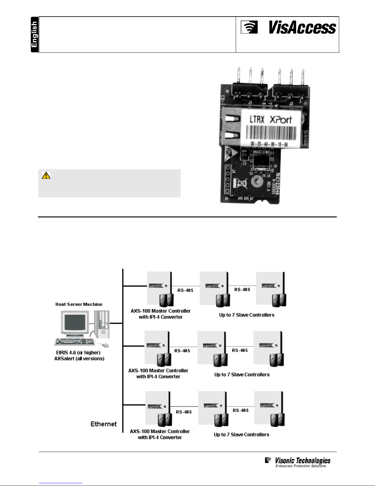
Typical System Configuration
Any combination of eight Master/Slave AXS-100/200 controllers (each with its own address) can be networked together on a single
RS-485 data loop to manage up to 16 doors. Each RS-485 data loop requires that one Master controller (whose address is #1)
be equipped with an IPI-4 Converter for communicating via 10/100 Ethernet V2.0 (TCP/IP) with the host server machine.
IPI-4 Converter – Installation Guide
Page 2 of 6
D-301285_V6.0
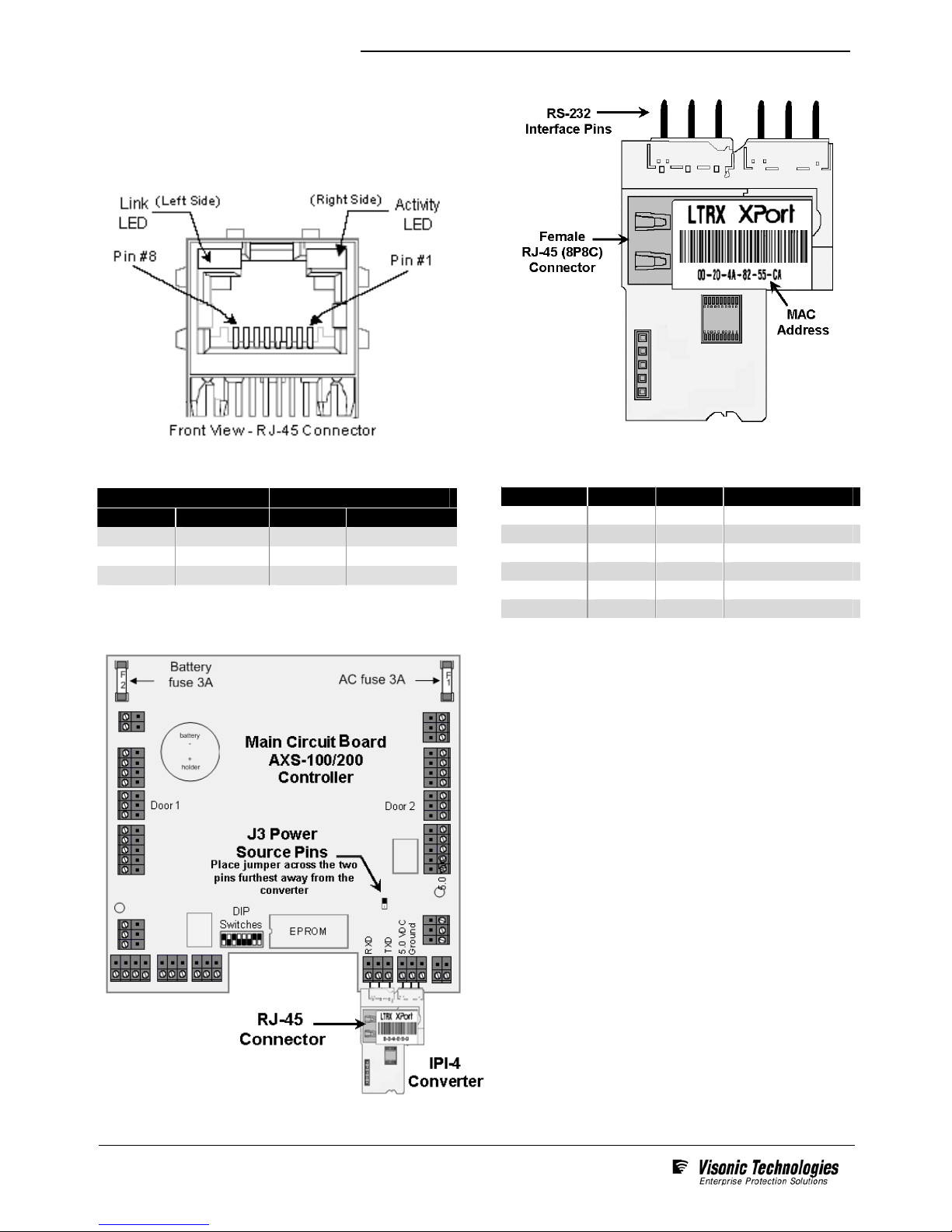
Electrical Interfaces
The IPI-4 contains one female RJ-45 (8P8C) connector for
linking the device to the LAN/WAN Ethernet network switch or
router. This requires a standard network 8-pin RJ45 terminated
patch cable (not included)
The pin configuration of the RJ-45 connector is detailed below:
Two bi-color Ethernet status LEDs are built into the front of the
Female RJ-45 connector as detailed below:
Link LED (Left Side) Activity LED (Right Side)
Color Meaning Color Meaning
Off
No Link
Off
No Activity
Amber
10 Mbps
Amber
Half-duplex
Green
100 Mbps
Green
Full-duplex
The IPI-4 also utilizes a 6 pin-rigid integrated connector for
connecting the converter to the AXS-100 master controller’s
RS-232 interface as detailed in the table below
Signal Dir Pin Function
RXD In 1 Serial Data
None 2 Not Used
TXD Out 3 Serial Data
+5.0 VDC In 4 Power
- 5 Ground
Not Used 6 Not Used
Installation and Hookup Details
1. Ensure tht the controller the IPI-4 is to be installed has
been set to position # 1 on the AXS-100 loop.
2. Power-down the AXS-100 controller and connect the
IPI-4 to the serial interface of the controller as shown.
3. To ensure that the controller will provide power to the
IPI-4, place J3’s power source jumper across the two
pins furthest away from the converter.
4. Using a RJ-45 terminated patch cable (not included)
connect the IPI-4 to the LAN/WAN Ethernet network
switch or router.
5. Power-up the AXS-100 controller; the IPI-4 converter will
also power-up and link to the Ethernet network.
 Loading...