

VisAccess AXS-100, AXS-100XT Installation Manual
AXS-100, AXS-100XT
Indoor Two-Door Proximity Access Control System
Installation Guide
1. INTRODUCTION
The AXS-100/AXS-100XT is an electronic access control system
for controlling two doors.. Eight controllers can be networked
together to control a total of 16 doors. The controller relay
activates a lock or an electromagnetic strike (EMS), when a valid
proximity key card or tag is presented to the reader. For detailed
system description, refer to the AXS-100/AXS-100XT user’s
guide.
The use of a proximity (non-contact) key makes the installation of
the AXS-100/AXS-100XT system an attractive possibility in harsh
environments and in places with poor lighting conditions.
The proximity keys are totally sealed and wear resistant. The lock
reads the key ID, whenever the key is held close to the reader.
2. SPECIFICATIONS
AXS-100, AXS-100XT CONROLLER
Power Input: 14 - 16.5 VAC, 50VA
Max Current Consumption: 2.5A
Memory Capacity: 5,000 access card codes
Event Log: 1000 records per controller
Event Printout: RS-232 channel to printer or PC
System Programming: From controller #1. PC may be connected for
use as supplemental monitoring only.
Time Schedules: 64 separate schedules. Each key may be assigned
to 2 schedules.
Dry Contact Relay: Max 1A continuous
Doors Per Controller: Up to 2
Readers Per Controller: Up to 2 external + 1 internal (for programming)
Controllers Per Network: 8
Inputs (x 2 doors): Request-to-exit, door position, 2 programmable
inputs
Outputs: 2 lock relays, NO/NC dry contact, 30VDC 2A max
1 auxiliary relay, NO/NC dry contact, 30V DC 2A max
Output power for 2 locks: 10.3 - 12VDC, 400mA max
2 readers output: 70 mA max
Anti Passback (APB) Modes:
1. Local to each controller
2. Network APB
Indicators (LEDs): 5 (see figure 5)
Operating Temperatures: 0°C to 50°C (32°F to 122°F)
Dimensions (LxWxD):
315x262x74mm (12-3/8x10-5/16x10-15/16 in)
Weight: AXS-100: 3.8 kg (8.4 lb)
AXS-100XT: 3 kg (6.6 lb)
Color: White
Compliance with standards: Complies with Part 15 of the FCC
Rules and RSS-210 of Industry and Science Canada.
Operation is subject to the following two conditions: (1) This
device may not cause harmful interference, and (2) this device must
accept any interference received, including interference that may
cause undesired operation.
READERS
Operating Temperatures: -20°C to 50°C (-4°F to 122°F)
Color: Dark brown
Minimum distance between readers: 60 cm (2 ft)
RDR-4 PROXIMITY READER
Weight: 121.5 g (4.3 oz)
Indicators: Tricolor LED (Green, Red, Amber)
Cable (to AXS-100/AXS-100XT control unit) maximum length:
22 AWG up to 60 m (200 ft)
18 AWG up to 100 m (320 ft)
Dimensions (LxWxD):
116 x 70 x 16.8 mm (4-1/2 x 2-3/4 x 5/8 in)
RDK-4 PROXIMITY READER WITH KEYPAD (optional, not evaluated by UL)
Weight: 170 g (6 oz)
Power input: 12-16V DC from the AXS-100 / AXS-100XT
Buttons: 12 (numeric keypad)
Dimensions (LxWxD):
122x82x31mm (4-13/16 x 3-1/2 x 1-1/4 in)
CARDS (*)
CRD-1SL ISO STANDARD SLOTTED AND NUMBERED
PROXIMITY CARD
Card ID: One of a trillion different combinations
Dimensions (LxWxD):
85x54x1mm (3 5/16 x 2 1/8 x 1/32 in)
Weight: 2.5 g (0.1 oz)
Color: White
CRD-25SL: Package of twenty-five CRD-1SL slotted proximity
cards with print
CRD-25: Package of twenty-five CRD-1 non-slotted proximity cards
(optional).
CRD-25S: Slotted proximity card
TAGS (*)
TAG-1: One proximity tag
* Both cards and tags contain 40-bit code and using
Manchester encoding
.
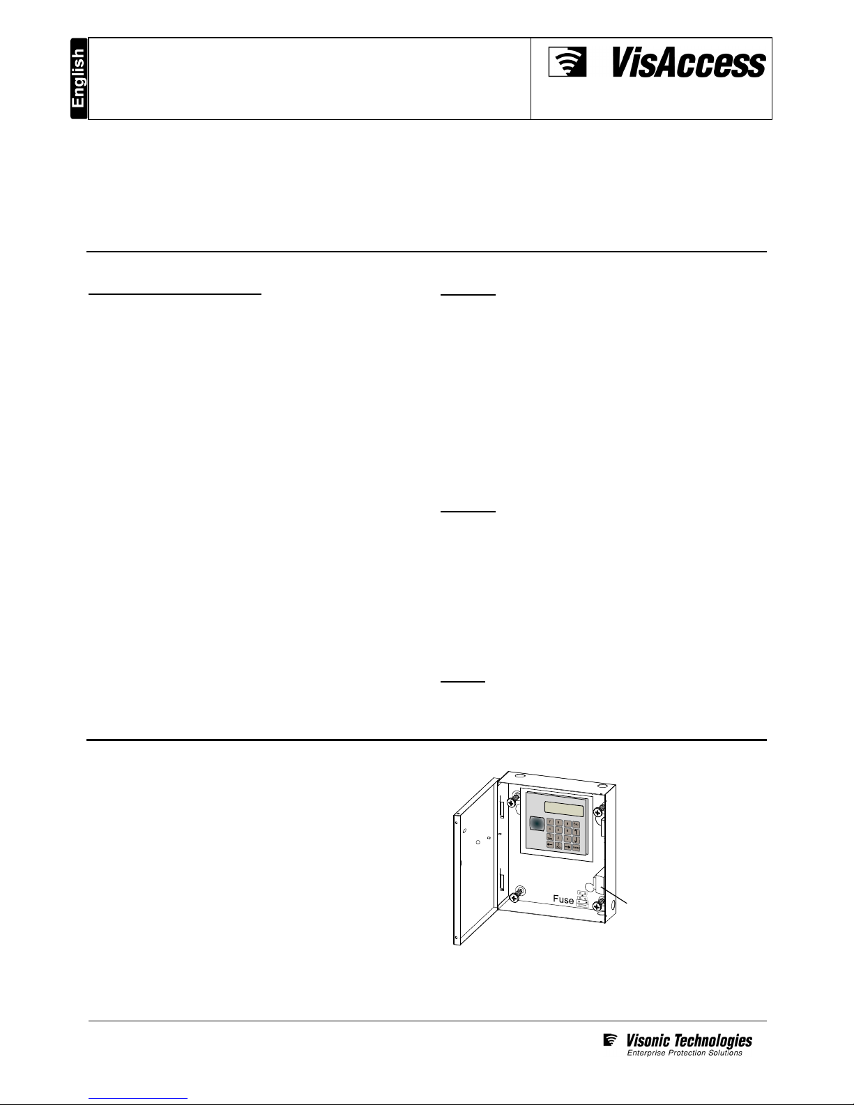
3. MOUNTING
3.1 Metal Box Mounting
The system must be installed indoors, within the protected
premise, in accordance with the National Electrical Code
(NFPA70) and the local authorities having jurisdiction.
For AXS-100XT use only the supplied plug-in transformer:
PRI 120V/60Hz @ 0.59A, SEC 16.5VAC / 50VA
BE116250CAA0040, Basler Electric, Class 2 NOT WET,
Do not connect (the transformer) to a power receptacle that is
controlled by a switch.
Use the box as a template
to mark on the mounting
surface, drill 4 holes on the
mounting surface and
fasten the box to the
mounting surface by using
4 screws.
Transformer (AXS-100 only).
In AXS-100XT there is no
transformer.
Figure 1 - Mounting
Page 1 of 5
DE6280-9
3.2 Metal Box Door Lock Assembly
The door lock assembly of the system metal box is presented in
figure 2 (the lock and the brass nut are supplied in the system
accessories box).
Metal box door
Metal box
Align lock with the prepunched hole and
insert it into the hole.
Place the brass nut on the
lock, tighten by hand and
finally tighten with
spanner (7/8”). Verify that
you can lock the door (key
rotation of 90 degrees).
2
1
Figure 2 - Metal Cabinet Door Lock Assembly
3.3 Backup Battery Installation (Optional)
Locate the optional backup battery (12V, 7.0Ah, Lead-acid
battery) in the lower left side of the system enclosure (see fig. 3).
3.4 Tamper Switch Installation & Wiring
It is necessary to protect the controller against tampering. A UL
Listed Tamper switch must be installed (see fig. 4) and wired to
AUXIN1 and COM of lock #3 of each controller.
Backup
battery
(optional)
Fig. 3 - Backup Battery
Fig. 4 - Tamper Switch Installation
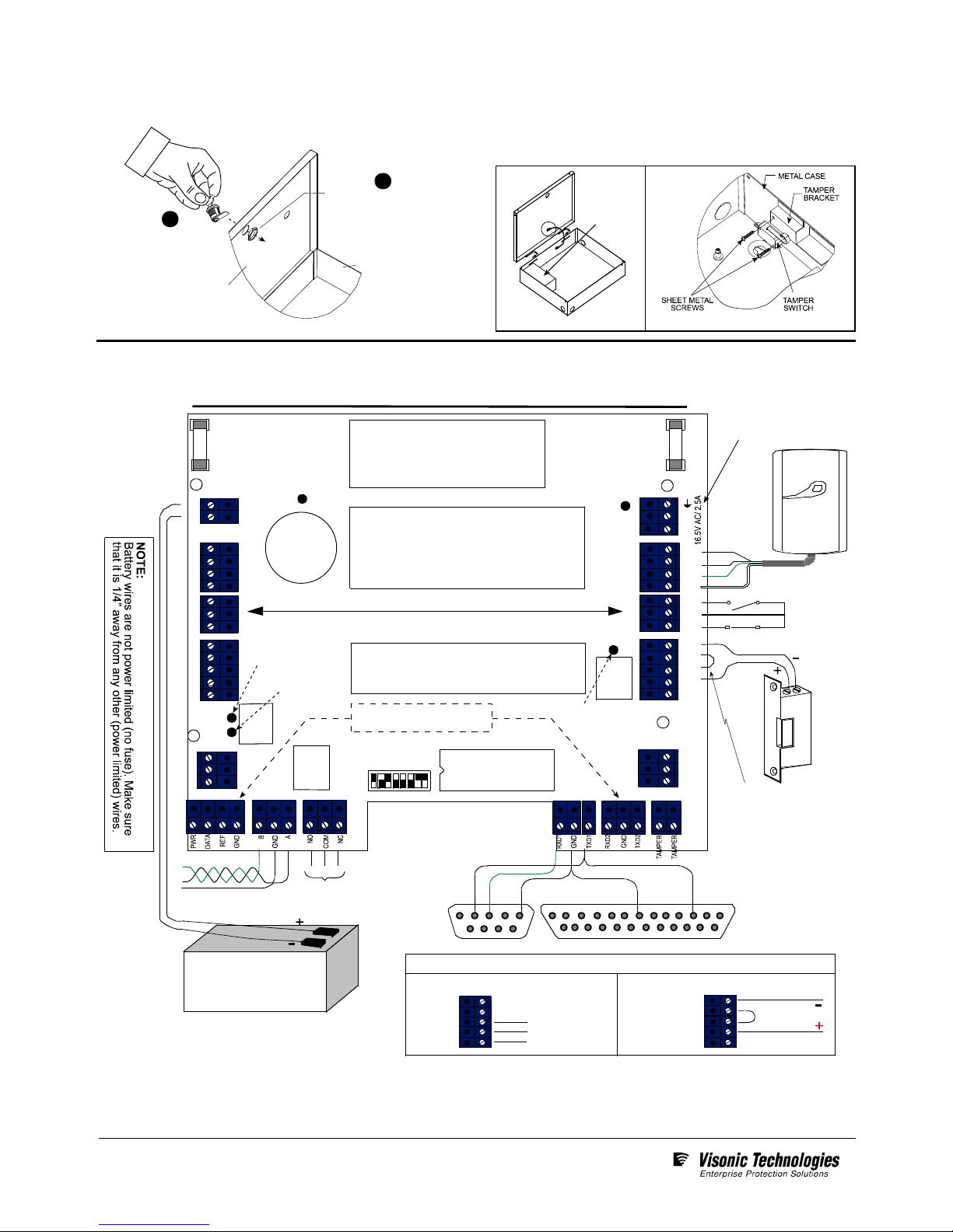
4. WIRING
1 2 3 4 5 .
6 7 8 9
13 12 11 10 9 8 7 6 5 4 3 2 1
25 24 23 22 21 20 19 18 17 16 15 14
EPROM
battery
-
+
holder
F
3
IN1
GND
IN2
Battery fuse 3.15A
Replace fuses (x2) with UL
Listed fuses.
WARNING: To reduce risk of
fire, replace only with the same
type and rate of fuse.
AC fuse 3.15A
PWR
GND
TX
RX
AC
AC
RTE
GND
DPOS
PWR
GND
NO
NC
COM
READER 2
RELAY 2
DOOR 2
Wire Jumper
(remove for dry contact)
READER 1
RELAY 1
DIP Switches
PWR
GND
TX
RX
BAT+
BAT-
RTE
GND
DPOS
PWR
GND
NO
NC
COM
12V, 7.0Ah
Lead-acid battery
(optional)
PWR
GND
N.O.
N.C.
COM
PWR
GND
N.O.
N.C.
COM
Lock connection configurations
Dry contact connection Internal 12V power supply
Normally open (EMS)
Common
Normally closed (maglock)
Twisted pair to A,B
of other AXS-100
Common gnd to
other AXS-100
must be connected!
Alarm relay
to Siren or
Bell
Door 1 Door 2
Symmetrical connectors
AXS-100, AXS-100XT Wiring Diagram
Prox. Reader
Red
Black
Green
White
RTE input
D.POS input
DB-9F
To computer
COM1 or COM2
DB-25M
To serial printer
F
2
DOOR 1
IN1
GND
IN2
NOTE:
Replace battery with PANASONIC.
Type: CR2032, 3V “COIN” battery.
Use of another battery may present
a risk of fire or explosion.
See user manuals for safety instructions.
NOTE:
All power outputs are power limited
except from the battery outputs
.
NOTE:
For battery
replacement
see
installation
instructions.
Note:
Optional for future use
LD2 (red LED)
Power ON
LD3 (green LED)
ext. batt. char ged
LD1 (green LED)
output relay
activated
LD4 (red LED) alarm
relay activ ated
LD5 (green
LED) output
relay activated
Plug-in transformer for AXS-100XT
only: PEI 120V/60Hz @ 0.59A,
SEC. 16.5VAC / 50VA.
BE116250CAA0040, Basler
Electric. Class 2 NOT WET,
UL Listed 49HO.
Figure 5 - Wiring
Page 2 of 5
DE6280-9
 Loading...