

VisAccess AXS-100, AXS-100ST Installation Manual
AXS-100 Slave Controller
For AXS-100 and AXS100XT Access Control Systems
Installation Guide
Introduction
The AXS-100 Slave Controller is a cost effective solution that
extends AXS-100 or AXS100XT access control system
functionality up to 16 doors on a single RS-485 data loop using
any combination of up to *8 ‘Master’ or ‘Slave’ controllers.
Each AXS-100 slave controller operates in real-time with
distributed intelligence and a full mirror database for offline
conditions. Should a communication failure occur between any of
the slaves and the master controller or between the master
controller and the host computer, each AXS-100 slave controller
will continue to function normally with no degradation in
performance and response times of card reading, alarm
activation or activation of logic events. Each AXS-100 slave can
also monitor the status of the protected doors (open or closed)
and the status of the door locks (locked or unlocked).
Initial system configuration is programmed via the master
controller’s keypad. Functionality such as event log access, card
holder programming and/or mode updates are handled via EIRIS
V4.6 (or higher) or AXSalert enterprise software.
*One ‘Master controller’ is required for each RS-485 data loop.
CAUTION: It is important that you read, understand, and
follow the instructions in this document. If you have
questions, call your local VT support representative.
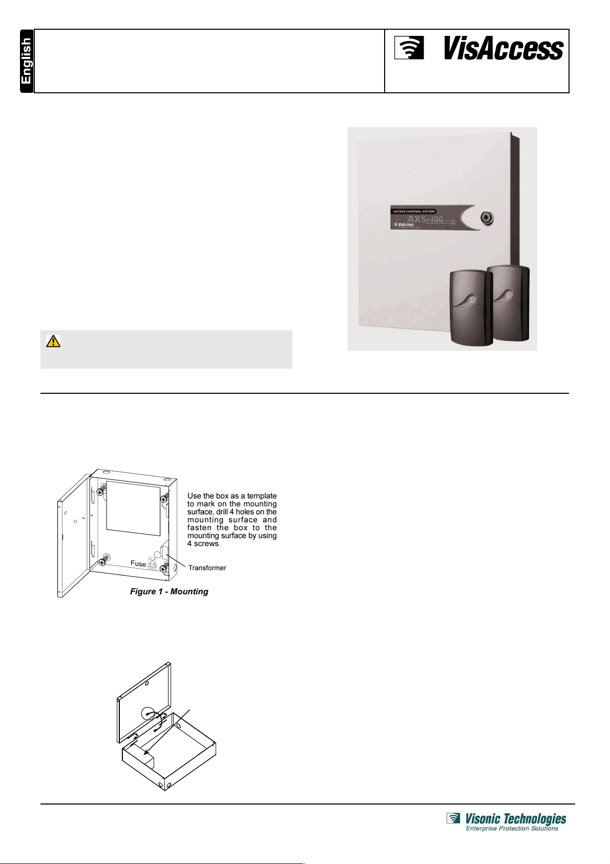
1. Mounting and Initial Assembly
A. Metal Box Mounting
The AXS-100 Slave Controller must be installed indoors, within
the protected premise, in accordance with the National Electrical
Code (NFPA70) and the local authorities having jurisdiction.
Note: Do not connect (the transformer) to a power receptacle that
is controlled by a switch.
B. Backup Battery Installation (Optional)
Locate the optional backup battery (12V, 7.0Ah, Lead-acid
battery) in the lower left side of the system enclosure (see fig. 2).
Backup
battery
(optional)
Fig. 2 - Backup Battery
Page 1 of 6
DE62821A_V7.0

C. Metal Box Door Lock Assembly
The door lock assembly of the system metal box is presented in
figure 3 (the lock and the brass nut are supplied in the system
accessories box).
Metal box door
Metal box
Align lock with the prepu n c h e d ho l e a n d
insert it into the hole.
Place the brass nut on the
lock, tighten by hand and
f i n a ll y t i g h t en w i t h
spanner (7/8”). Verify that
you can lock the door (key
rotation of 90 degrees).
2
1
Figure 3 - Metal Cabinet Door Lock Assembly
D. Tamper Switch Installation & Wiring
It is necessary to protect the controller against tampering. A UL
Listed Tamper switch must be installed (see fig. 4) and wired to
AUXIN1 and COM of lock #3 of each controller.
Fig. 4 - Tamper Switch Installation
Page 2 of 6
DE62821A_V7.0
 Loading...