

VISA VE-S42T, VE-S60T User Manual
ISTRUZIONI PER IL MONTAGGIO E L’USO
(x4)
(x4)
DEL SUPPORTO A PARETE
PER SCHERMI LCD/PLASMA
Avvertenze:
Attenzione
Attenzione
Attenzione
Una struttura adeguata deve poter sopportare il peso o il carico
Non procedete con l’istallazione se la struttura è soggetta a
Non installare vicino a radiatori, camini, alla luce diretta del sole,
Per l’installazione è necessaria la presenza di almeno due
Superfici consigliate per il montaggio: assi in legno e pareti in
La struttura della parete deve essere in grado di sopportare un
peso massimo di almeno 75 kg (165 lbs) per televisori da 37”-60”
e 56 kg (123 lbs) per televisori 25”-42”, altrimenti deve essere
rinforzata. Anche il personale tecnico qualificato deve attenersi
alla procedura di installazione come riportata nelle istruzioni. Il
mancato rispetto delle istruzioni di montaggio può comportare
lesioni gravi o mortali.
Durante l’installazione del prodotto vanno sempre seguite le
normali misure di sicurezza. Utilizzate attrezzi e strumenti adatti
alla procedura di installazione per evitare lesioni.
Prima di procedere all’installazione del supporto, leggete
attentamente le istruzioni per il montaggio, assicurandovi di
averle comprese bene, per evitare di procurare lesioni alle
persone e danneggiare gli oggetti. Conservate con cura le
istruzioni per eventuali consultazioni future.
dello schermo. Se il montaggio viene effettuato su di una parete
in assi di legno, individuate esattamente il centro dell’asse prima
di procedere con l’installazione.
vibrazioni, movimenti o può essere urtata. In tal caso, il
televisore o la superficie su cui è montato potrebbero riportare
danni.
condizionatori o a qualsiasi altra fonte di calore o di energia. Lo
schermo potrebbe riportare dei danni e aumenta il rischio di
incendi.
persone qualificate. In caso di rovesciamento o di errata
manipolazione lo schermo può causare lesioni o subire
danneggiamenti.
muratura. Se il supporto deve essere installato su una superficie
diversa dalle assi in legno, si consiglia di utilizzare gli attrezzi
adatti (reperibili in commercio)
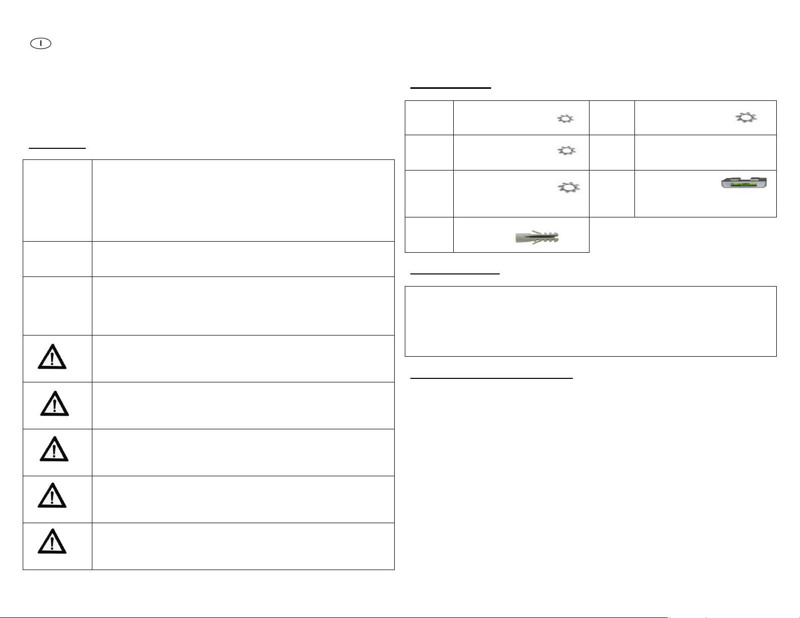
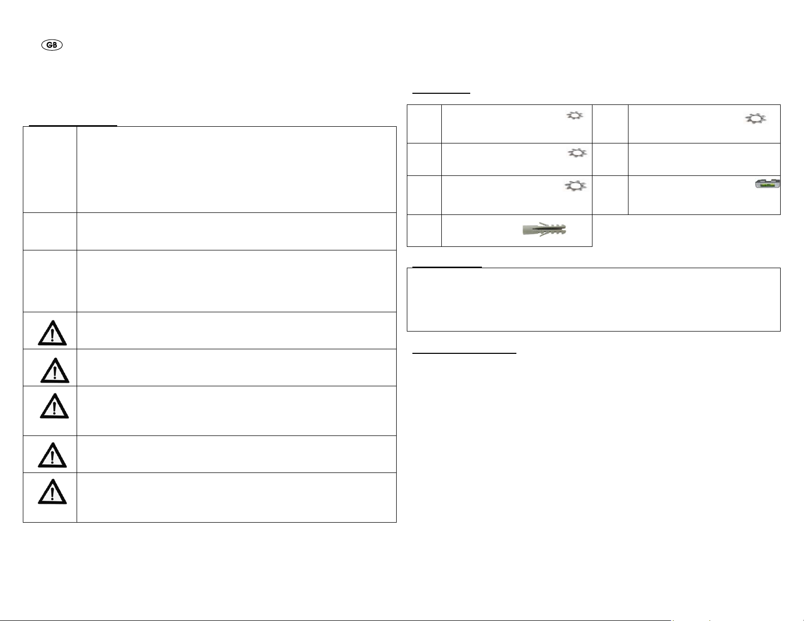
Kit degli attrezzi:
Bustina
1
Bustina
2
Bustina
3
Bustina
7
Attrezzi necessari:
Metro e matita
Cacciavite a stella
Rilevatore di legno per installazione su muri a secco
Chiave a bussola da 8 mm
Trapano elettrico con punta da 10mm per l’installazione su pareti in
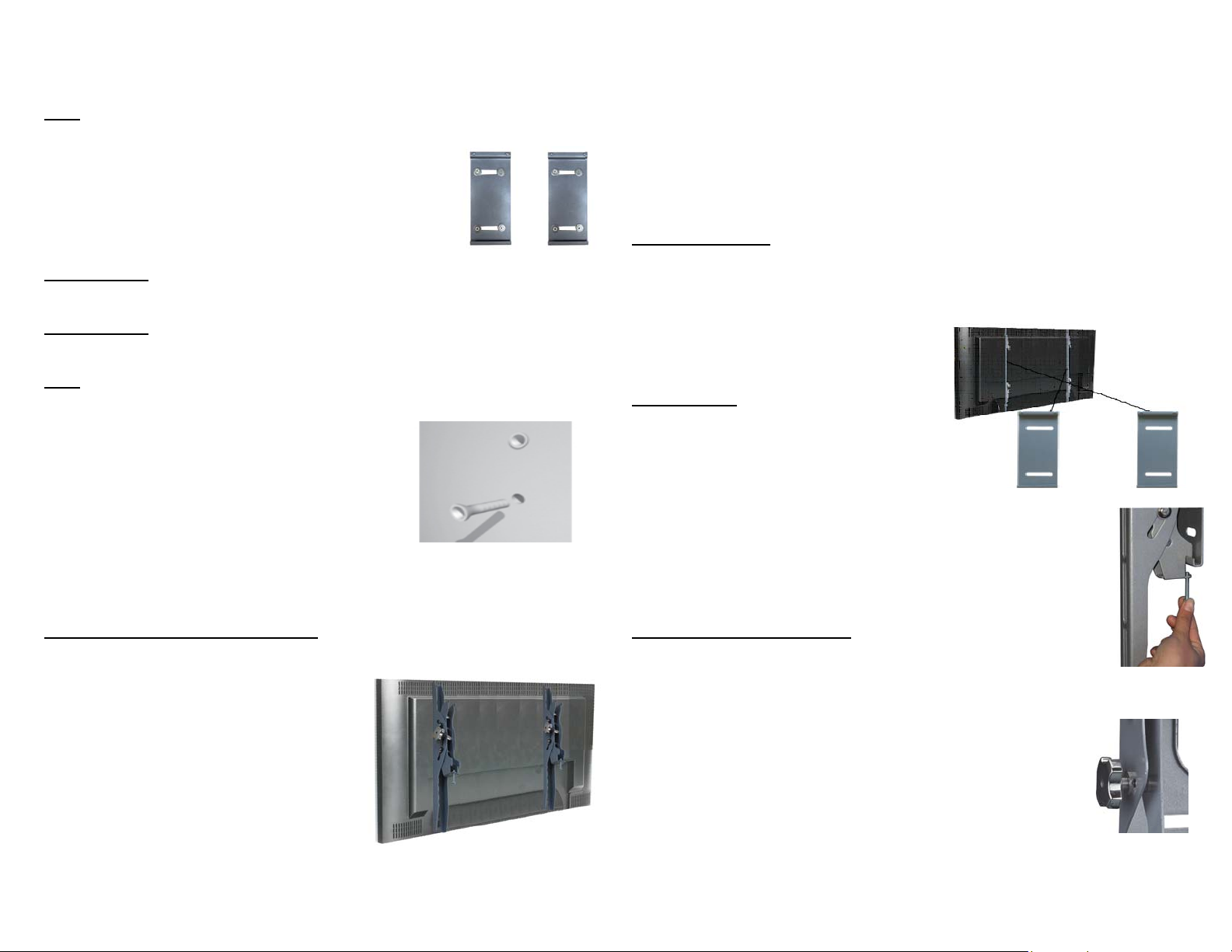
Installazione della placca a parete
1. Prima di procedere con l’installazione è necessario misurare la distanza
2. Con una matita tracciate una linea orizzontale nel punto in cui desiderate
3. Collocate le due placche a parete al di sotto della linea orizzontale,
4. Segnate a destra, a sinistra, in alto e in basso, le posizioni dei piccoli fori
5. Quindi, praticate un foro con il trapano e la punta di 8mm in corrispondenza
6. Con l’aiuto di un assistente, collocate la placca sulla parete e allineate i fori
(x4) Vite M4x12
(x4) Vite M4x30
Rondella dentellata M4
(x4) Vite M5x12
(x4) Vite M5x30
(x4) Rondella dentellata M5
(x4) Vite M6x12
(x4) Vite M6x35
(x4) Rondella ntellata M6
(x8) Tasselli 10x50
muratura.
orizzontale che intercorre tra i fori sul retro del televisore che si vuole
montare a parete e prenderne nota.
collocare il televisore, assicurandovi che sia parallela al suolo e di
lunghezza almeno pari alla distanza tra i fori sul retro del televisore.
assicurandovi che i margini superiori siano sulla linea e che i due elementi
siano a una distanza pari alla distanza tra i fori.
orizzontali nelle due placche a parete. Dovreste segnare in totale quattro
punti per ciascun elemento.
di ciascun segno.
per il montaggio con i fori che avete praticato nel muro.
de
Bustina
4
Bustina
5
Bustina
6
(x4) Vite M8x16
(x4) Vite M8x40
Rondella dentellata M8
(x4) Distanziatore M4/M5
(x4) Distanziatore M6/M8
(x4) Rondella M4/M5
(x1) Sistema di
livella a bolla
(x8) Tirafondo di 7,5 cm
(x8) Rondella
N.B.: Se state effettuando l’installazione su pareti con assi in legno
assicuratevi che tutti i fori si trovino sulle assi. Quindi riprendete dal punto
7a, oppure andate al punto 7b.
7a. Inserite un tirafondo e una rondella in ciascun
foro e nella parete.
8a. Stringete le viti con la chiave a bussola
girandole in senso orario fino ad avvitarle bene.
ATTENZIONE: Non stringete mai eccessivamente le viti, poiché si può
danneggiare inutilmente la parete. Evitate una torsione eccessiva.
ATTENZIONE: Non lasciate la placca fino a quando non è stata adeguatamente
assicurata alla parete.
N.B.: Per l’installazione su parete in muratura devono essere utilizzati gli
appositi tasselli per il fissaggio a muro(solo per fissaggio a parete piena).
7b. Inserite un tassello per pareti in muratura
in ciascun foro.
8b. Se necessario, servitevi di un martello
per inserire delicatamente ciascun fissaggio a filo
con la parete.
9b. Una volta che tutti i fissaggi sono stati
posizionati riposizionate la placca.
10b. Inserite una vite tirafondo e una rondella attraverso la placca in ciascun
tassello.
11b. Stringete soltanto quando tutte le viti sono in posizione.
Installazione dei bracci del televisore
1. Per permettere un’istallazione corretta,
in questo kit troverete varie viti con
diversi diametri e lunghezze.
2. Posizionate il televisore su una
superficie morbida e liscia e
localizzate i fori filettati per il
montaggio collocati sul retro dello
schermo.
3. Scegliete la vite più adatta, verificando
con una cannuccia o uno stuzzicadenti
la lunghezza del foro.
4. Se il retro del televisore è curvo o
convesso è necessario utilizzare un distanziatore.
N.B.: Scegliete il distanziatore che si adatta meglio alla curvatura per
mantenere i bracci il più possibile vicini allo schermo.
5. Collocate il distanziatore tra i bracci del telaio e il televisore.
6. Se state usando le viti più piccole (M4, M5 o M6) è consigliabile utilizzare
una rondella per ciascuna vite al fine di rendere la struttura più stabile.
Installazione finale
Agganciate ciascun braccio al televisore allineando i fori che si trovano su di
esso con i fori filettati sul pannello posteriore del televisore, inserendo le viti in
entrambi e avvitando in senso orario sino a quando non risultino completamente
inserite.
1 on un cacciavite a stella.
. Avvitate c
ATTENZIONE:
fase è necessaria la presenza di due
persone.
2
. Per compl
supporto per schermi Lcd/Plasma,
disponete con cautela i bracci del televisore sopra la barra
superiore e inferiore del telaio.
Altra caratteristica del supporto a parete è la sicura che non
permette di rimuovere il televisore dalle due placche a parete. Per
utilizzare la sicura è sufficiente avvitare le viti al di sotto dei bracci
del televisore e stringerle bene.
Funzionamento e regolazione
Potete regolare l’inclinazione del televisore utilizzando le manopole
collocate a destra e a sinistra dei bracci del televisore.
1. Innanzi tutto, ruotate le manopole in senso antiorario per
allentare le barre del telaio.
2. Per regolare l’inclinazione del supporto verso l’alto, spingete
sulla traversa superiore per inclinare il supporto a vostro
piacimento, quindi ruotare leggermente la manopola fino alla
sua chiusura. Per regolare l’inclinazione del supporto verso il
basso, spingete sulla traversa inferiore per inclinare il
supporto a vostro piacimento, quindi ruotare leggermente la manopola fino
alla sua chiusura.
3. Quando avrete regolato correttamente il supporto in base alla necessità,
stringete nuovamente il telaio ruotando le manopole in senso orario.
Per portare a termine questa
etare l’installazione del
LCD/PLASMA MOUNT INSTALLATION
AND OPERATION INSTRUCTIONS
Warning Statements
Warning
Warning
Warning
Do not install on a structure that is prone to vibration, movement
Do not install near heater, fireplace, direct sunlight, air
At least two qualified people should perform the installation
Recommended mounting surfaces: wooden studs and solid-flat
The wall structure must be capable of supporting at least a
maximum weight of 75kgs(165lbs) for 37”-60” televisions and
56kgs(123lbs) for 25”-42” televisions. If not, the wall must be
reinforced. Proper installation procedure by a qualified service
technician, as outlined in the installation instructions, must be
adhered to. Failure to do so could result in serious personal
injury, or even death.
Safety measures must be practiced at all times during the
installation of this product. Use proper safety gear and tools for
the installation procedure to prevent personal injury.
Prior to the installation of this product, the installation instructions
should be read and completely understood. The installation
instructions must be read to prevent personal injury and property
damage. Keep these installation instructions in an easily
accessible location for future reference.
A secure structure must support the weight or load of the display,
When mounting to a wall that contains wooden studs, dead
center of the wooden stud must be confirmed prior to installation.
or chance of impact. Failure to do so could result in damage to
the display and/or damage to the mounting surface.
conditioning or any other source of direct heat energy. Failure to
do so may result in damage to the display and could increase the
risk of fire.
procedure. Injury and/or damage can result from dropping or
mishandling the display.
concrete. If the mount is to be installed on any surface other than
wooden studs, use suitable hardware (which is commercially
available).
Hardware kit:
Bag
1
Bag
2
Bag
3
Bag
Tools Required:
Tape Measure & Pencil
Phillips Head Screw driver
Stud finder for drywall installation
5/16” Socket and Wrench
Electric drill and 10mm masonry bit for concrete/brick installation
(x4) M4x12 Bolt
(x4) M4x30 Bolt
(x4) M4 Lock Washer
(x4) M5x12 Bolt
(x4) M5x30 Bolt
(x4) M5 Lock Washer
(x4) M6x12 Bolt
(x4) M6x35 Bolt
(x4) M6 Lock Washer
(x6) Concret
anchor 10x50
7
Bag 4
Bag 5
Bag 6
(x4) M8x16 Bolt
(x4) M8x40 Bolt
(x4) M8 Lock Washer
(x4) M4/M5 Spacer
(x4) M6/M8 Spacer
(x4) M4/M5 Washer
(x6) Bubble Level System
(x6) 3” Lag Bolt
(x6) Washer
Wall plate installation
1. Before installa
tion, you need measure the horizontal distance of the holes
on the back of the television you want to install and get the data.
2. Use pencil to draw a horizontal line on the place you want to install your
television, making sure the the line must be horizontal to the ground and at
least as wide as the width of the horizontal hole distance on back of your TV.
3. Place the two pieces of wall plate under the horizonal line, making sure the
upper edge of the wall plates on the same level with the line and the hole
distance falling into the wall plates.
4. Mark the right (upper and lower) and the left (upper and lower) positions of
the small horizontal slots in the two wall plates. You should mark four
positions on each wall bracket.
5. Next, pre-drill a 10mm hole in the wall at each marked location.
6. With the help of an assistant, position the wall plate against the wall and line
up the mounting slots with drilled holes.
Note: If you install on wood wall, make it sure that all the hole must be on
the studs! Then please go 7a. , or you need go 7b!
7a. For each location, insert a lag bolt and
washer into the wall.
8a. Tighten bolt with an open ended socket
wrench by turning clockwise until tight.
CAUTION: Do not over-tighten bolts-doing so
may cause unnecessary damage to the wall.
Avoid excessive torque.
CAUTION: Do not release the wall plate until it
is properly mounted and secured to the wall.
NOTE: The concrete anchors must be used for concrete or brick wall. They
can be purchased at your local hardware store.
7b. Insert a concrete anchor into each hole.
8b. If necessary, a hammer can be used to
lightly tap each anchor into place so that
they are flush with the wall.
9b. Once all of the anchors are in place,
move the wall plate back into position.
10b. Attach the nut onto the threaded shaft
that is protruding from the wall.
11b. Do not tighten until all nuts are in place.
Display Bracket Installation
1. To ensure optimal installation, this kit includes various screws of different
diameters and lengths.
2. Place your TV screen down on a soft, flat surface, and locate the threaded
mounting points that are located on the back of the display.
3. Determine which screw is the correct length by carefully inserting a straw, or
toothpick, and mark how deep the mounting point is.
4. If your display has a curved back or a
recessed thread mounting point, a
spacer must be used.
NOTE: Select the spacer that is
closest in depth to the recess to keep
your bracket as close to the displ
ay as
possible.
5.
Place the spacer between the
mounting bracket and the display.
6. If a smaller screw is being
used(M4,M5 or M6), please use a
washer with each screw for added
stability.
inal Installation
F
Attach each brack
et to the display by
aligning the holes on each bracket,
with the threaded inserts on the back
panel of your display, inserting the
screws through both and turning
clockwise until they are fully inserted.
1. Tighten with a Phillips head screw
driver.
CAUTION:
Two people are required
for this step.
2. To complete the installation of your
new lcd/plasma mount, carefully
brackets over the upper and lower mo
place the television
unting crossbars.
er feature of your display mount is the lock designed to
Oth
pr
vent your television fro
e m being removed from the two wall
plates. To use the security function, you only need to thread
the screws under the TV brackets till it locked the bracket
tightly.
Operat
Y
ion and Adjustment
ou can adjust the tilt of your television by using the tension knob located on the
right-hand side and left-hand
1. First, turn the tension kn
side of the TV brackets.
obs counter-clockwise to loosen the mounting
crossbars.
2. To tilt the mount up, press the right knob as you pull on the lower part, while
at the same time pushing on the upper crossbar to tilt the
mount to the position you want, then release the knob
and push slightly until it locked.
To tilt the mount down, press the right knob as you pull
3.
on the upper crossbar, while at the same time pushing on
the lower crossbar to tilt the mount to the position you
want, then release the knob and push slightly until it
locked.
Once the desired level of tilt is achieved, retighten the mo
4. unt by turning the
tension knobs clockwise.
 Loading...