

Visa VE-PL50T User Manual
LIBRETTO ISTRUZIONI E DI
MONTAGGIO DEL SUPPORTO
TV LCD/PLASMA
Prima di iniziare con l’installazione del supporto per lo schermo piatto,
verificate di avere a portata di mano tutti gli attrezzi necessari. Per installare
il supporto in maniera appropriata sono necessari i seguenti attrezzi:
?? giravite
?? trapano elettrico e punte da muratura 5/16” (8mm) per
cemento/mattoni
Assicuratevi inoltre che, insieme al supporto, vi sia stato fornito tutto
l’occorrente per il montaggio. Nella confezione dovete trovare sette buste
contenenti i seguenti articoli:
Busta Articolo (Ref) Busta Articolo (Ref)
4 bulloni M4x12 (A)
1
4 bulloni M4x30 (B)
4 rondelle M4 (C)
4 bulloni M5x12 (D)
4 bulloni M5x30 (E)
2
4 rondelle M5 (F) 5
4 bulloni M6x12 (G)
3
4 bulloni M6x35 (H)
4 rondelle M6 (I)
2 viti di bloccaggio di sicurezza (S)
7
2 dadi di sicurezza (V)
Fase 1 – Montaggio del supporto a parete
NOTA: Al momento di inserire le viti nella parte superiore del supporto,
assicurarsi che sia inclinato al massimo verso il basso cosicché la staffa
superiore non sia di intralcio. Inclinare il supporto completamente verso
l’alto quando si inseriscono le viti nella parte inferiore, in modo da evitare
che la staffa inferiore sia di intralcio. Per indicazioni su come regolare
l’inclinazione vedasi “Messa in opera e regolazione” nella Fase 3.
Installazione su cemento/mattoni
Iniziare posizionando a piombo il supporto sulla parete servendosi della
livella incorporata. Segnare i punti in cui praticare i sei fori necessari a
fissare il supporto; rimuovete quindi il supporto. Con il trapano elettrico
munito di punta da muratura 5/16” (8mm), praticare i sei fori, facendo
attenzione a rimuovere dal loro interno la polvere di trapanatura. Inserire
quindi un tassello per cemento (P) in ciascun foro. Se necessario, utilizzare
delicatamente il martello per inserire il tassello nel foro per assicurarsi che
sia a filo con la parete.
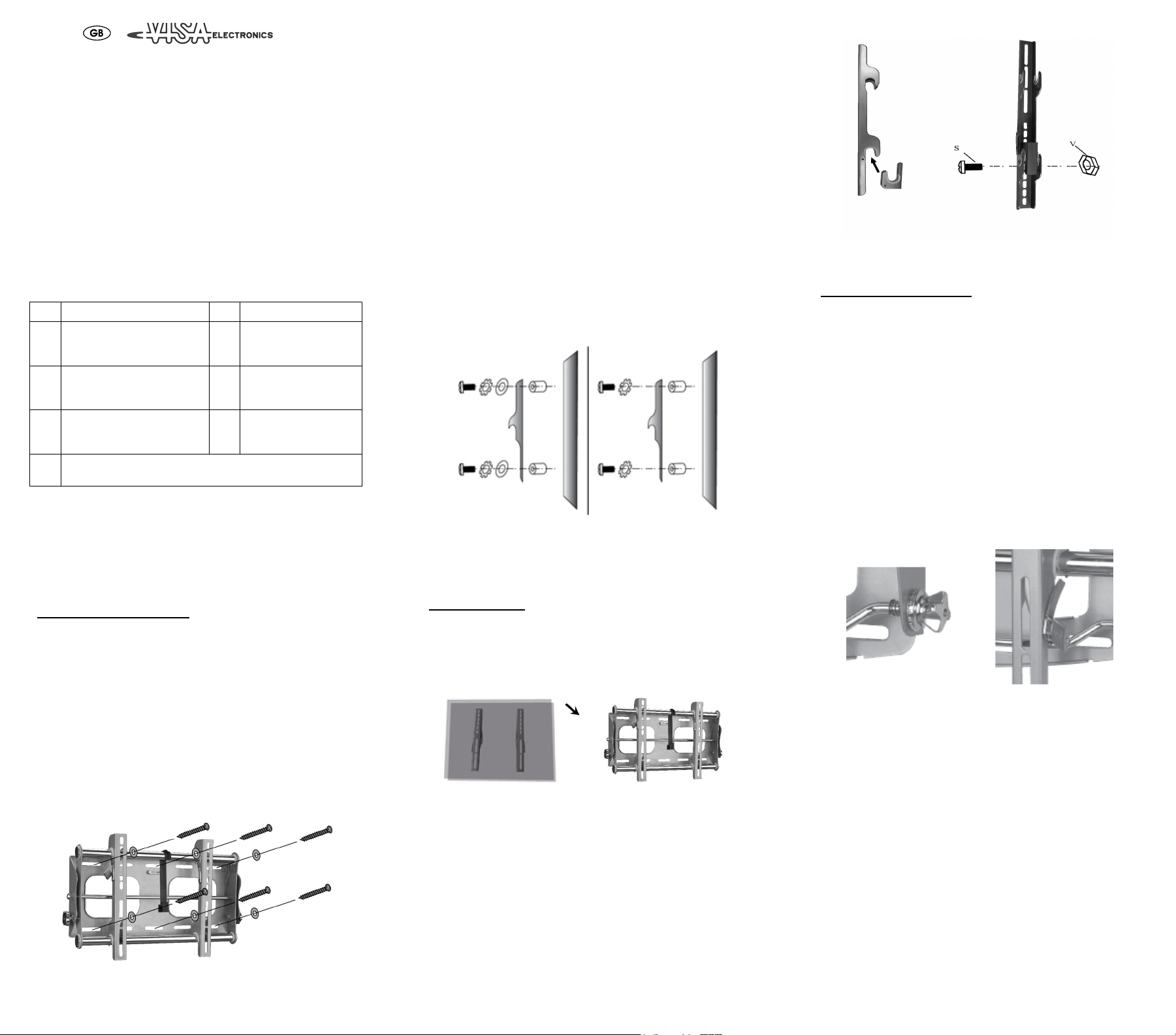
Una volta installati tutti i tasselli, posizionare nuovamente il supporto quindi
inserire una vite (Q) e una rondella piana (R) in ciascun tassello (figura A),
assicurandosi che le viti siano ben avvitate ma senza stringerle
eccessivamente.
Figura A
4 bulloni M8x16 (J)
4
4 bulloni M8x40 (K)
4 rondelle M8 (L)
4 distanziali M4/M5
(M)
4 distanziali M6/M8 (N)
4 rondelle piane M4/M5
(O)
6 tasselli (P)
6
6 bulloni M8x63 (Q)
6 rondelle piane (R)
Fase 2 – Fissare i bracci al televisore
IMPORTANTE: non effettuare MAI il montaggio con il TV collegato
alla rete elettrica e/o con lo schermo appoggiato in giù per evitare danni
sulla sua superficie.
Verificare innanzitutto di quali pezzi si ha bisogno. Iniziare esaminando il
retro del televisore per stabilire la lunghezza dei bulloni: per un apparecchio
con il retro piatto si utilizzano generalmente bulloni corti, mentre per quelli
con il retro ricurvo o incavato si usano bulloni più lunghi. Determinare
quindi il diametro dei bulloni da impiegare. Il kit di montaggio contiene
bulloni di quattro dimensioni: provarli tutti fino a trovare quello adeguato.
Non forzare un bullone eccessivamente lungo: al primo sentore di resistenza
interrompere l’operazione per evitare di danneggiare il televisore.
Utilizzando i bulloni e le rondelle delle giuste dimensioni, fissare i bracci al
retro del televisore. Per i bulloni più piccoli (M4/M5) utilizzare le rondelle
piane (O). Per televisori con retro ricurvo o incavato potrebbe essere
necessario anche un distanziale (M o N; figura B). Assicurarsi che tutti i
bulloni siano ben avvitati ma senza stringere eccessivamente
Bulloni M4/M5 Bulloni M6/M8
Figura B – Per televisori con retro ricurvo o incavato
Fase 3 – Installazione finale e messa in
opera
Installazione finale
Per completare l’installazione del supporto, appoggiare delicatamente il
televisore, cui sono già stati fissati i bracci, alle due staffe orizzontali del
supporto a parete (figura C). Per i televisori più pesanti potrebbe essere
necessario l’intervento di due persone.
Bracci Supporto a parete
Figura C
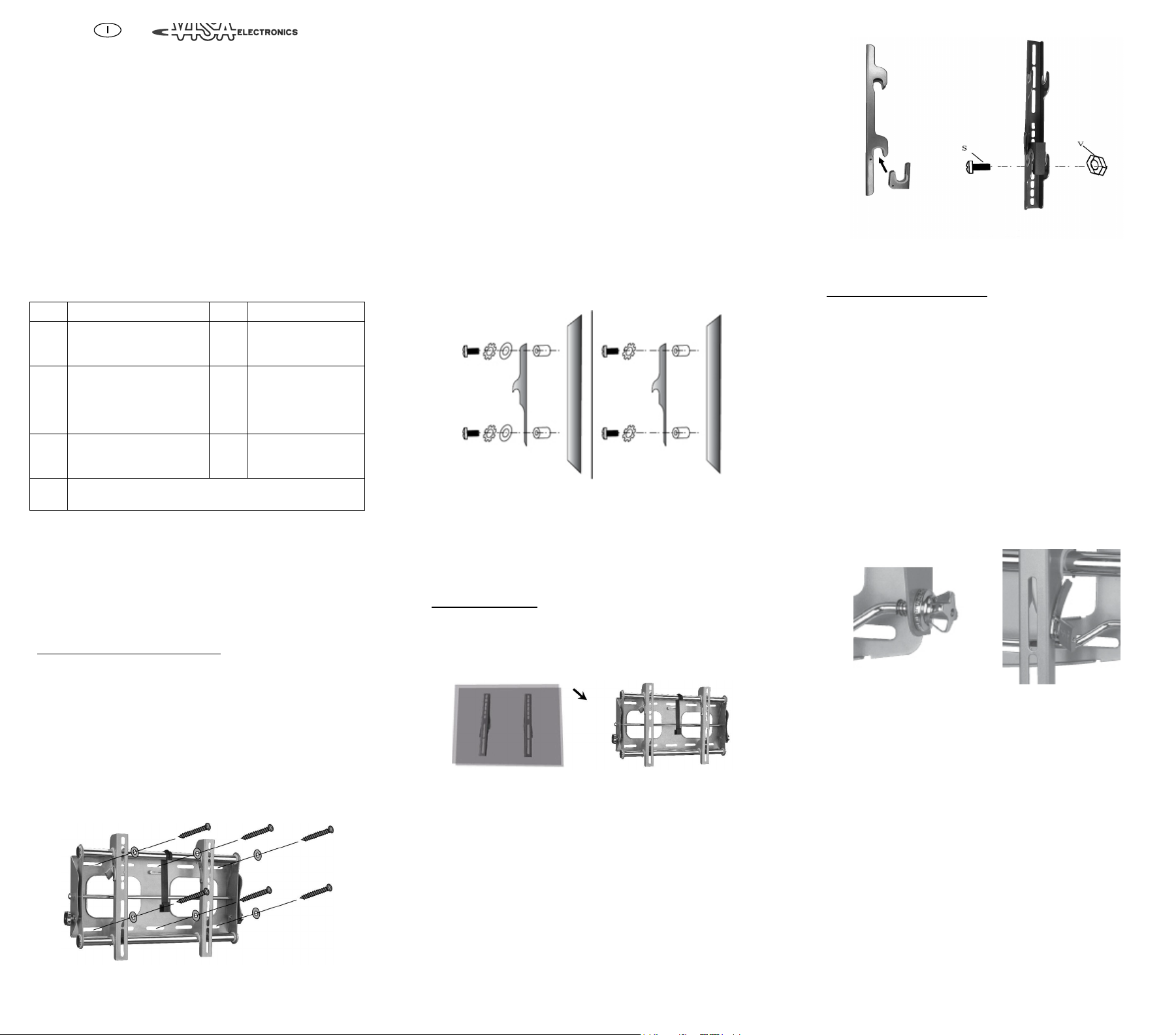
Per il bloccaggio del TV oltre ai fermi descritti nella sezione “Messa in
opera e regolazione” è stato fornito un ulteriore kit come sistema di
sicurezza ( 7 ), che serve ad evitare che il televisore possa incidentalmente
staccarsi dal supporto. Posizionare un elemento di sicurezza dietro ciascun
braccio, immediatamente sotto la staffa orizzontale inferiore. Per fissare gli
elementi di sicurezza, inserire una vite di bloccaggio di sicurezza (S) nei fori
del braccio, così da farlo passare attraverso l’elemento di sicurezza. Inserire
quindi il dado di sicurezza (V) all’estremità di ciascuna vite (figura D).
Figura D - Braccio e sistema di sicurezza
Messa in opera e regolazione
Il supporto a parete può essere regolato in base alle esigenze individuali di
ogni utente. L’inclinazione si regola tramite le manopole di regolazione
situate su entrambi i lati del supporto. Allentare le manopole facendole
ruotare in senso antiorario. Tenere sempre fermo il televisore con una mano
per evitare che si possa muovere nel momento in cui vengono allentate le
manopole. Posizionate ora il televisore nell’angolo di inclinazione
desiderato. Stringere quindi le manopole, una alla volta, per fissare
l’angolazione stabilita (figura E) (Tilt).
Insieme al supporto sono stati forniti anche una borchia fermacavi e due
fermi di sicurezza da utilizzare per evitare che il televisore possa essere
rimosso. La borchia fermacavi si collega alla staffa orizzontale e si usa per
avvolgere i cavi in modo ordinato. Per applicare i fermi di sicurezza,
individuare le alette metalliche situate sui bracci che si fissano al televisore.
Spingere i fermi verso l’interno in modo tale che, sollevando il televisore,
queste tocchino la staffa. Inserire un piccolo lucchetto (non incluso nella
confezione) attraverso i fori che si trovano sui fermi e sui bracci del
supporto per impedire la rimozione del TV (figura F).
Figura E Figura F
GARANZIA
Mediante la presente garanzia, il Produttore si impegna a sostituire il
prodotto solo in caso di difetti di fabbricazione che limitano l'utilizzo dello
stesso come previsto.
La presente garanzia non copre incidenti diretti o indiretti e danni risultanti
dall'utilizzo del prodotto, infortuni, manomissione, mancato rispetto delle
istruzioni, uso improprio, negligenza e qualsivoglia altro utilizzo.
Il Produttore non potrà in alcun caso essere considerato responsabile per
eventuali incidenti.
La presente garanzia copre tutte le altre garanzie, implicite e/o esplicite.
Il Produttore è l'unica autorità responsabile della presente garanzia.
Nessun altra parte ha diritto di interpretare eventuali responsabilità emerse
prima e dopo la vendita del prodotto.
La presente garanzia limitata si estende solo al primo acquirente originale
per un periodo di 5 anni.
INSTRUCTIONS AND
ASSEMBLY OF WALL MOUNT
FOR LCD/PLASMA TV
Before beginning the installation of your new flat screen mount, first verify
that you have all of the necessary tools at hand. The following tools are
required for proper installation:
?? Phillips screwdriver
?? Electric drill and 5/16” (8mm) masonry bit for concrete/brick
installation
Also make sure that all of the hardware has been included with your mount.
You should find six bags containing the following:
Bag Item (Ref) Bag Item (Ref)
x4 M4x12 Bolt (A)
1
x4 M4x30 Bolt (B)
x4 M4 Lock Washer (C)
x4 M5x12 Bolt (D)
2
x4 M5x30 Bolt (E)
x4 M5 Lock Washer (F)
x4 M6x12 Bolt (G)
3
x4 M6x35 Bolt (H)
x4 M6 Lock Washer (I)
x2 Safety Guard Bolt (S)
7
x2 Safety Guard Nut (V)
Step 1 – Mount the Wall Plate
NOTE: When inserting screws into the top of the mount, make sure the tilt
is fully adjusted downward so that the top crossbar is out of the way. Fully
adjust the tilt upward when inserting screws into the bottom to avoid the
same problem with the bottom crossbar. See “operation and adjustment”
in Step 3 for information on adjusting the tilt.
Concrete/Brick Installation
Begin by placing the wall plate into position against the wall, using the
bubble guide to keep it level. Mark off six holes to be used for securing the
mount and place the wall plate aside. Next, drill holes using an electric drill
and 5/16” (8mm) masonry bit. After drilling, remove any dust left in the
hole. Next, insert a Concrete Anchor (P) into each hole. If necessary, a
hammer can be used to lightly tap each anchor into place so that they are
flush with the wall.
Once all of the anchors are in place, move the wall plate back into position.
Screw a Drywall Screw (Q) and Drywall Washer (R) into each anchor (see
Diagram A). Make sure all screws are snug, but do not over-tighten.
x4 M8x16 Bolt (J)
4
x4 M8x40 Bolt (K)
x4 M8 Lock Washer (L)
x4 M4/M5 Spacer (M)
5
x4 M6/M8 Spacer (N)
x4 M6 Washer (O)
x6 Concret anchor (P)
6
x6 M8x63 lag bolt (Q)
x6 Lag bolt washer (R)
Step 2 – Attach Arms to the Television
IMPORTANT: Make sure the television is unplugged before starting
this step of the installation and never lay your television face down as
this can damage the viewing surface.
You must first determine which hardware to use with your television.
Begin by examining the back of the television to establish the length of bolt
required: a television with a flat back usually requires a shorter bolt while
those with a curved or recessed back take a longer bolt. Next, determine
which diameter bolt to use. Four different diameter bolts have been
included with your installation kit. Test each diameter bolt with your
television until you find the one that fits. Take care not to force a bolt that
is too large; if you feel any resistance, stop immediately to avoid damaging
your television.
Next, attach the arm brackets to the back of the television using the correct
size bolt and lock washer. If your television uses one of the smaller
diameter bolts (M4/M5), use a Washer (O). Televisions with a curved or
recessed back may also require a spacer (M or N; see Diagram B). Make
sure all bolts are secure, but do not over-tighten.
M4/M5 Bolts M6/M8 Bolts
Diagram B – For televisions with curved or recessed backs
Step 3 – Final Installation and Operation
Final Installation
To complete the installation of your new plasma mount, carefully place the
television with attached arm brackets over the cross-bars on the wall plate
(see Diagram C). Heavier televisions may require two people to lift safely.
Your mount also includes two safety guards to prevent the TV from
accidentally being knocked off of the mount. To use the guards, place one
behind each arm directly under the bottom crossbar. To secure each guard,
place a Safety Guard Bolt (S) through the holes in the arm so that is passes
through the guard piece. Next, place a Nut (V) on the end of each bolt (see
Diagram D).
Diagram C
Diagram D
Operation and Adjustment
Your new wall mount can be adjusted to suit your individual needs. You
can adjust the tilt of your television by using the adjustment knobs located
on both sides of the wall plate. Loosen both knobs by turning them counterclockwise one at a time. Always use one hand to support the television so
that it does not move suddenly once the knobs are loosened. After the
knobs are loosened, position your television at the desired level of tilt.
Finally, re-tighten the knobs one at a time to lock the tilt level in place (see
Diagram E).
Other features of your display mount include a cord manager and lock
designed to prevent your television from being removed from the cross-bar.
The cord manager attaches to the cross-bar and can be used for neatly
routing your television’s power cable. To use the security lock, locate the
small metal tabs located on the arm brackets that attach to the television.
Push these tabs inward so that lifting up on the television causes the tabs to
come into contact with the cross-bar. Place a small padlock (not included)
through the holes located on the tabs and arm brackets to prevent the tabs
from being moved out of place (see Diagram F).
Diagram E Diagram F
WARRANTY
Manufacturer by this warranty engage itself to only replace this product in
case of workmanship defects causing limitation to the use of the product
as described.
This warranty does not cover direct or indirect incidents, and damages
resulting from the use of this product, accidents, tampering, inability to
follow the instructions, mishandling, neglect and any other use.
Manufacturer will at no time be liable for any incidents.
This warranty covers all the other warranties, be they implied and/or
expressed.
The Manufacturer is the sole authority for this warranty, no others are
Diagram A
allowed to interpret any liabilities before and after sales of this product.
This limited warranty only extends to the first original purchaser for
5 years .
 Loading...