

VISA VE-L55-T User Manual
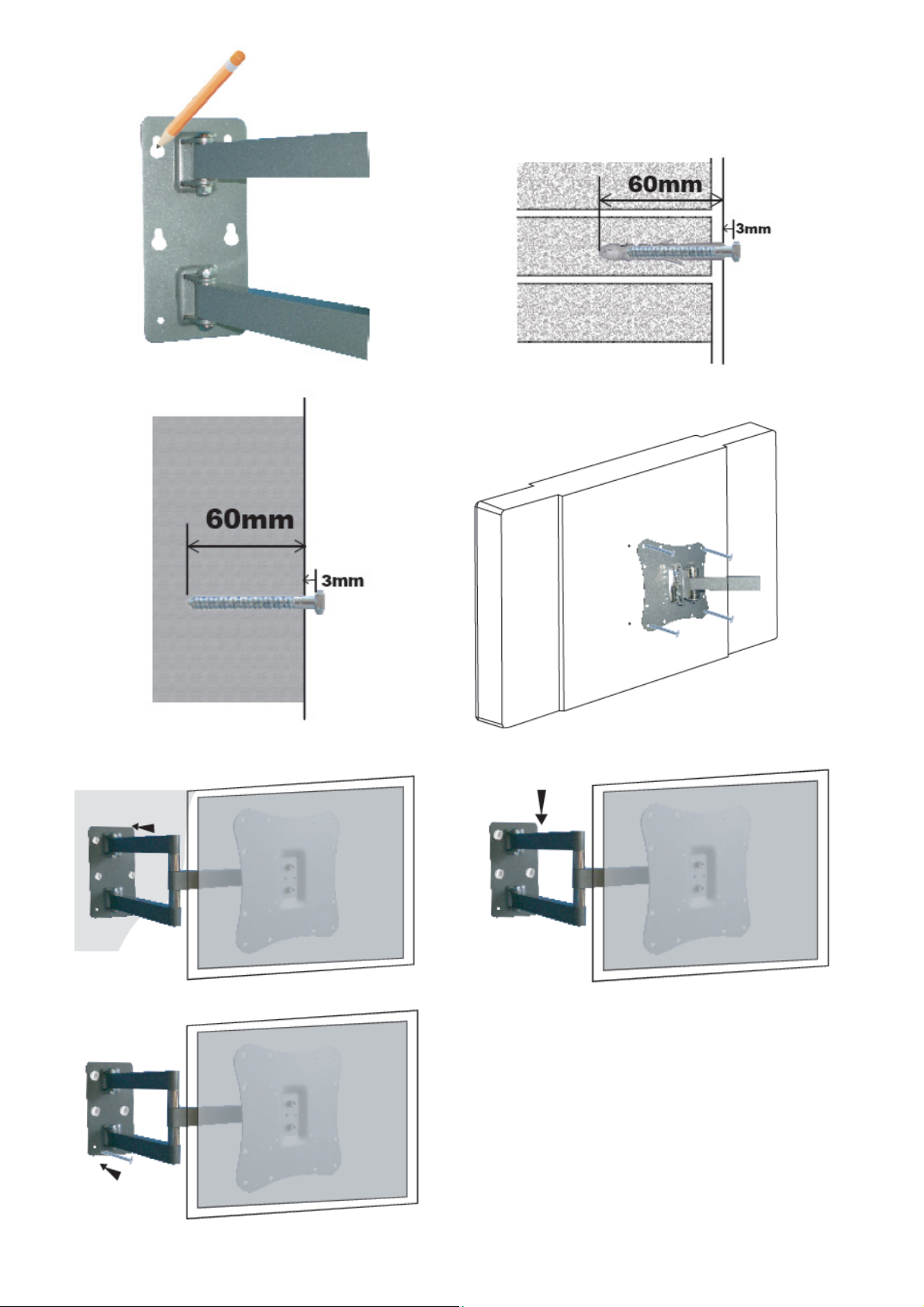
Fig.1 Fig. 2
Fig. 2a Fig. 3
Fig.4 Fig. 4a
Fig. 4b
Libretto istruzioni e di montaggio del supporto per Monitor / TV LCD/PLASMA
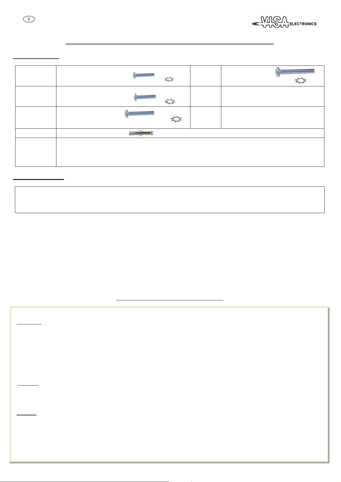
Kit degli attrezzi:
Bustina 1
Bustina 2
Bustina 3
Bustina 7
Bustina delle
viti per
l’assemblaggio
(x4) Vite M4x12
(x4) Vite M4x30
(x4) Rondella dentellata M4
(x4) Vite M5x12
(x4) Vite M5x30
(x4) Rondella dentellata M5
(x4) Vite M6x12
(x4) Vite M6x35
(x4) Rondella dentellata M6
(x6) Tasselli 10x60
(x4) Vite Allen M8x15
(x4) Dado M8
(x4) Rondella M8
(x2) Chiave Allen S=6; S=4
Bustina 4
Bustina 5
Bustina 6
Attrezzi necessari:
Cacciavite a stella
Rilevatore di legno per installazione su pareti a secco
Chiavi a bussola
Trapano elettrico e punta da 10mm per l’installazione su pareti in muratura.
ATTENZIONE:
Seguire attentamente istruzioni e schemi di montaggio prima di installare ed utilizzare il supporto.
Si declina ogni responsabilità in caso di mancata osservazione delle istruzioni, delle limitazioni d’uso e per modifiche apportate al prodotto.
PRECAUZIONI:
La portata massima del supporto è indicata sulla scatola. Non sovraccaricare il supporto per nessun motivo
L’installatore deve assicurarsi della validità e della consistenza della parete dove sarà applicato il supporto, ev itando strutture non sufficientemente robuste per questo
tipo d’uso.
Il prodotto è adatto per installazioni su pareti in mattoni pieni in laterizio, in cemento armato, oppure in legno pieno o travi in legno. Per applicazioni su
legno si possono usare esclusivamente le viti autofilettanti in dotazione prive del tassello. Per l’installazione su pareti di materiali diversi, vi consigliamo di
rivolgervi ad un installatore qualificato.
Il prodotto non è idoneo ad ambienti esterni
(x4) Vite M8x16
(x4) Vite M8x40
(x4) Rondella dentellata M8
(x4) Distanziatore M4/M5
(x4) Distanziatore M6/M8
(x4) Rondella M4/M5
(x6) Tirafondo di 5,5 cm
(x6) Rondella
STEP 1 – Montaggio della base di ancoraggio
Attrezzatura:
a) Scegliere la posizione dove installare il prodotto, evitando punti dove passano tubi dell’acqua
o cavi elettrici.
b) Appoggiare la base del supporto sulla parete nella posizione desiderata e contrassegnate i sei fori sulla parete.( vedi fig. 1 )
Per pareti in muratura: eseguire la foratura con l’uso del trapano; inserire i tasselli (bustina 7),
avvitare soltanto le 4 viti superiori (bustina 6) senza stringerle completamente lasciando almeno 3mm dal muro(vedi fig.2).
N.B. il supporto verrà posizionato al muro soltanto dopo averlo fissato al TV/Monitor.
Per pareti in legno:eseguire la stessa procedura del punto b senza però eseguire la foratura per i tasselli.
STEP 2 – Montaggio del braccio sul pannello posteriore del TV/Monitor LCD/PLASMA
Importante:
Esaminare la parte posteriore del TV/Monitor LCD/PLASMA:
- se la superficie è piana, fissare il braccio senza utilizzare i distanziatori (vedi fig. 3);
- altrimenti scegliere il Kit adeguato .
Attenzione
STEP 3 - Assemblaggio finale
Per completare l’installazione,
- posizionare il supporto con il TV/Monitor LCD/PLASMA montato,facendo passare la testa dei quattro bulloni già fissati al muro nelle quattro apposite fessure
poste sulla base del supporto.( vedi Fig. 4)
- far scorrere il supporto verso il basso in modo che i bulloni arrivino a fine corsa della fessura (vedi Fig. 4a ).
- inserire i due restanti bulloni nei fori ancora liberi nella piastra posteriore del supporto e stringere completamente tutti i bulloni. (vedi Fig. 4b)
trapano, punte in widia da 10mm, cacciavite.
Non effettuare MAI il montaggio con il TV/Monitor LCD/PLASMA collegato alla rete elettrica e/o con lo schermo appoggiato in giù per evitare danni
sulla sua superficie.
a non stringere troppo i bulloni.

Regolazioni:
Sulla maggior
parte dei modelli, è possibile regolare l’angolo d’inclinazione in verticale ( Tilt ) attraverso la manopola di c olore grigio posta sulla piastra del supporto
fissata al TV/Monitor LCD/PLASMA.
Svitare ruotando la manopola in senso anti-orario, regolare l’inc
linazione e stringere di nuovo per bloccare la nuova posizione.
Si possono effettuare altre regolazioni del punto di visione, spostando il braccio nella posizione desiderata.
Se il fissaggio dei punti di rotazione (swivel) risultasse troppo lento o troppo stretto, si possono allentare o stringere attr
averso l’apposita chiave Allen(4).
Manutenzione:
Per la pulizia utiliz
zare un panno inumidito con una soluzione di acqua tiepida e sapone neutro.
Non utilizzare solventi
- - - - - - - - GARANZIA - - - - - - - -
Mediante la presente garanzia, il Produttore si impegna a sostituire il prodotto solo in caso di difetti di fabbricazione che limitano l'utilizzo dello stesso come previsto.
La presente garanzia non copre incidenti diretti o indiretti e danni risultanti dall'utilizzo del prodotto, infortuni, manomissione, mancato rispetto delle is truzioni, uso
improprio, negligenza e qualsivoglia altro utilizzo.
Il Produttore non potrà in alcun caso essere consid
erato responsabile per eventuali incidenti.
La presente garanzia copre tutte le altre garanzie, implicite e/o esplicite.
Il Produttore è l'unica autorità responsabile della presente garanzia. Nessun altra parte ha diritto di interpretare ev
entuali responsabilità emerse prima e dopo la vendita
del prodotto.
La presente ga
ranzia limitata si estende solo al primo acquirente originale per un periodo di anni.
5
Instructions and assembly of wall mount for LCD/PLASMA
TV / Monitor
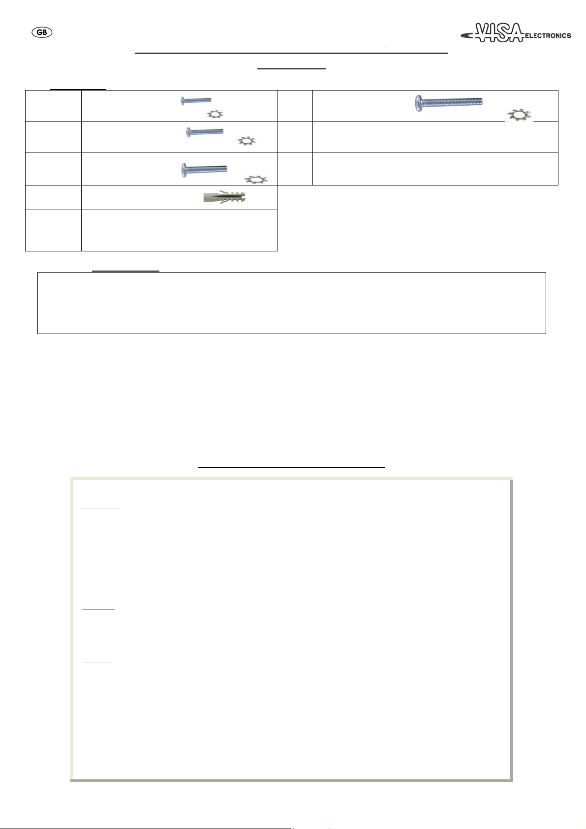
Hardware kit:
Bag 1
Bag 2
Bag 3
Bag 7
Assembling
Screws
bag
Tape Measure & Pencil
Phillips Head Screw driver
Stud finder for drywall installation
Socket and Wrench
Electric drill and 10mm masonry bit for concrete/brick installation
PLEASE NOTE:
Study the following instructions and assembly diagrams with care prior to installing and using the mount.
We do not accept any responsibility for failure to follow the instructions and limits of use and for any alterations made to the product.
PRECAUTIONS:
The wall mount’s maximum capacity is shown on the box. Do not overload the mount for any reason.
The person responsible for installation must check the soundness and firmness of the wall which the produc t will be mounted on, avoiding walls that are not strong
enough for this type of use.
The product is suitable for mounting on walls made of bricks, reinforced concrete, wood or wooden beams. The self-tapping screws provided may be used
without the wall anchors when mounted on wood. We recommend you use a qualified installer to mount the product on walls made of other material.
(x4) M4x12 Bolt
(x4) M4x30 Bolt
(x4) M4 Lock Washer
(x4) M5x12 Bolt
(x4) M5x30 Bolt
(x4) M5 Lock Washer
(x4) M6x12 Bolt
(x4) M6x35 Bolt
(x4) M6 Lock Washer
(x6) Concret anchor 10x60
(x4) 8x15 Allen Screw
(x4) M8 Nut
(x4) M8 Washer
(x2) S=4; S=6 Allen Wrench
Tools Required:
(x4) M8x16 Bolt
Bag
Bag
Bag
(x4) M8x40 Bolt
4
(x4) M8 Lock Washer
(x4) M4/M5 Spacer
(x4) M6/M8 Spacer
5
(x4) M4/M5 Washer
(x6) 3,5” Lag Bolt
(x6) Washer
6
The product is not suitable for use outdoors
STEP 1 – Mounting of platform
Equipment: Drill, 10mm widia bits ,screwdriver.
a) Choose the position where you wish to install the product, avoiding spots crossed by water
pipes or electrical cables.
b) Place the mount platform on the wall in the desired position and mark the six (6) holes on the wall (see fig. 1).
For brick walls: make the holes in the wall using the drill. Insert the wall anchors (bags no. 7), insert only the UPPER screws
avoiding to completely tighten them keeping the screws at around 3mm from the wall (see fig. 2)
NOTE: this wall mount will be definitively fixed on the wall just after it is fixed on the TV/monitor screen.
For WOOD walls: execute the above procedure (b) without making the holes for the anchors
STEP 2 – Mounting the arm on the LCD rear panel
Important: *) NEVER mount the wall mount ith the LCD/PLASMA screen plugged in and / or
*) with the screen faced downwards (to avoid screen surface damages).
Check the rear side of the LCD/Plasma screen:
- if this surface is flat, mount the arm of wall mount without any spacer (see fig.3);
- otherwise choose the suitable spacers kit
Warning: Avoid over-tightening the screws.
STEP 3 – Final mounting
To complete installation:
- carefully insert the wall mount support (with the LCD/Plasma screen mounted on it) such as the four slots in the wall mount
basis are fit into the four screws before placed on the wall (see fog. 4);
- carefully move down the wall mount support till the screws placed on the wall reach the end strokes of corresponding slots
(fig. 4a)
- insert the other screws in the corresponding holes and
- fully tighten all the screws (fig. 4b)
 Loading...