

Page 1
MANUAL DE INSTRUCCIONES
OPERATING INSTRUCTIONS
MODE D’ EMPLOI
GEBRAUCHSANWEISUNG
MANUALE D’ISTRUZIONI
MANUAL DE INSTRUÇÕES
Tronzadora Abatible
Tiltable Mitre Saw
Tronçonneuse Inclinable
Gehrungssäge
Troncatrice Regolabile
Serra de Esquadria
TM72C / TS72C / TM73C / TS73C
Page 2

2
TRONZADORA ABATIBLE
Con mesa superior: Modelos TM72C y TM73C
Sin mesa superior: Modelos TS72C y TS73C
NOTA IMPORTANTE
¡ATENCIÓN! Antes de utilizar la máquina lea atentamente el FOLLETO DE INSTRUCCIONES GENERALES DE SEGURIDAD que se adjunta con la
documentación de la misma.
Conserve adecuadamente el FOLLETO indicado
y el presente MANUAL para posibles consultas
posteriores.
1. CARACTERÍSTICAS TÉCNICAS
Modelo..........................................TM72C y TS72C
Versión................................................Monofásica
Motor......................................................50 o 60 Hz
Potencia absorbida.....................................1200 W
Servicio....................................................12/48 min
Revoluciones en vacío (50 Hz)...................3000/min
Diámetros hoja de sierra........................300x30 mm
Modelo...........................................TM73C y TS73C
Versión......................................................Trifásica
Motor........................................................50 o 60 Hz
Potencia absorbida......................................1300 W
Servicio....................................................12/48 min
Revoluciones en vacío (50 Hz)...................3000/min
Diámetros hoja de sierra.........................300x30 mm
Plato Giratorio
Orientable a derecha e izquierda hasta 45° con
enclave jo en las posiciones a 0°, 15°, 22° 30', 30°
y 45°. Además permite la posibilidad de jarlo en
regulaciones de grados intermedios.
Cabezal Basculante
Abatible desde 90° a 45° respecto a la base y en
cualquier posición de giro del plato desde 0° hasta
45° en sentido izquierdo del mismo.
Dimensiones de la Máquina.....................Ver (Fig. 3)
Dimensiones del embalaje...........720x600x530 mm
Peso orientativo
(sin embalaje)............30 Kg (modelos con mesa sup.)
26 Kg (modelos sin mesa sup.)
2. CAPACIDADES MÁXIMAS DE CORTE
Corte a 0°x 90°(Fig. 9).Ver dibujo A.........80x150 mm
Corte a 0°x 45°(Fig. 12).Ver dibujo B.......65x150 mm
Corte a 45°x 90°(Fig. 15).Ver dibujo C......80x103 mm
Corte a 45°x 45°(Fig. 16).Ver dibujo D........63x60 mm
Corte sobre la mesa sup.Ver dibujo E (*).....máx.35mm
(*) Unicamente para modelos TM72C y TM73C
3. DESEMBALAJE DE LA MÁQUINA
En el interior de la caja de embalaje, Ud. encontrará
los siguientes elementos (Fig. 1):
Para modelos TM72C y TM73C
- Tronzadora según modelo
- Conjunto escuadra mesa
- Conjunto tope regulación madera
- Adaptador aspiración
- Juego llaves allen e/c 8 mm.
- Manual de Instrucciones y documentación diversa
Para modelos TS72C y TS73C
- Tronzadora según modelo
- Conjunto tope regulación madera
- Adaptador de aspiración
- Juego llaves allen e/c 8mm
- Manual de Instrucciones y documentación diversa
Para el transporte, la máquina lleva el Cabezal
bloqueado en su posición inferior por lo que para
desembalarla es su ciente con sujetar la máquina
ESPAÑOL
MANUAL DE INS TRUC CIO NES
OPERATING INSTRUCTIONS
MODE D'EMPLOI
GEBRAUCHSANWEISUNG
MANUALE D'ISTRUZIONI
MANUAL DE INSTRUÇÕES
página/page
Seite/pa gi na
ESPAÑOL Tronzadora Abatible
2
ENGLISH Tiltable Mitre Saw
7
FRANÇAIS Tronçonneuse Inclinable
11
DEUTSCH Gehrungssäge
15
ITALIANO Troncatrice Regolabile
20
PORTUGUÉS Serra de Esquadria
25
Page 3

3
por los laterales de la base inferior y extraerla de
la caja. Se recomienda realizar esta operación entre
dos personas como mínimo.
4. PREPARACIÓN Y PUESTA A PUNTO
¡ATENCIÓN! Asegúrese que la máquina está
desconectada de la red eléctrica antes de realizar
cualquier operación de preparación o mantenimiento
de la misma.
4.1 INSTALACIÓN
Para el empleo de la máquina en puesto jo, recomendamos su jación sobre una mesa o banco de
trabajo, con una altura aproximada de 90 cm, mediante
los agujeros A previstos en la base (Figs. 2 y 3). Se
recomienda la utilización de nuestro accesorio MESA
DE TRABAJO TRANSPORTABLE (Ref. 5800100).
Los modelos de tronzadora trifásicos salen conectados
de fábrica para una tensión de 380 V, siendo necesario que el usuario proceda a implantar una toma de
corriente en el cable de alimentación adecuada a su
instalación pero siempre con una capacidad mínima
de 16 Amperios. Además, y una vez conectada la
máquina a la red, es indispensable vericar que el
sentido de giro de la hoja coincida con el indicado en
el disco o en la tapa exterior de la máquina. De no
coincidir se deberá proceder a invertir el conexionado
de dos de las fases en la clavija de toma de corriente
montada.
La máquina está prevista exclusivamente para trabajos
en interior por lo que no debe ser expuesta a la lluvia
ni a los ambientes muy húmedos.
4.2 DESBLOQUEO DEL CABEZAL
La máquina sale de fábrica con el Cabezal bloqueado
en posición de transporte. Para su desbloqueo, deberá procederse a efectuar sobre la empuñadura B
una suave presión hacia abajo al mismo tiempo que
se presiona la palanca de color naranja y se tira del
pomo E (Fig. 4), situado en la parte posterior del lateral
derecho del cabezal, girándolo 90° hasta colocarlo
en posición de reposo. A continuación acompañar
la máquina en su movimiento de elevación hasta su
enclave en la posición de reposo.
4.3 COMPROBACIONES
Antes de conectar la máquina a la red, asegúrese del
buen estado de funcionamiento de los protectores y
mecanismos de seguridad.
Así mismo compruebe que la frecuencia y tensión de
la red corresponden con lo indicado en la placa de
características de la máquina. No conecte nunca la
tronzadora a una red de alimentación que no esté provista de una buena toma de tierra y del correspondiente
relé diferencial de protección, y de un dispositivo de
protección contra cortocircuitos por sobreintensidad
(p.ejemplo: fusibles)
En el caso de que se utilice un cable de prolongación,
vericar que la sección de los conductores sea ade-
cuada a la longitud de los mismos y a la intensidad
nominal de la máquina.
4.4 CAMBIO DE TENSIÓN
Sólo para los modelos TM73C y TS73C: De serie, las
máquinas salen preparadas de fábrica para una tensión
trifásica de 380V, en el caso en que se desee cambiar
su conexionado para una tensión trifásica de 220V se
recomienda que dicho cambio sea efectuado en un
Servicio Ocial de Asistencia Técnica VIRUTEX.
5. ELEMENTOS DE SEGURIDAD
5.1 INTERRUPTOR PARO-MARCHA
La tronzadora dispone en su empuñadura de un botón
verde que permite la puesta en marcha de la máquina,
y adyacente a éste va provista de un botón rojo que
provoca la inmediata parada de la misma.
En la modalidad de tronzado, con el cabezal basculante
levantado en posición de reposo (Fig. 7), pulsar el
botón de color verde H y accionar la palanca I de la
empuñadura, bajando esta última suavemente para
efectuar el corte.
¡ATENCIÓN!
No iniciar el corte hasta que la hoja no haya alcanzado
la plena velocidad de giro.
No forzar la sierra. El bloqueo total o parcial del motor
puede dar lugar a graves averías.
5.2 PROTECCIÓN CONTRA PUESTAS EN
MARCHA ACCIDENTALES POR CORTES
DEL SUMINISTRO ELÉCTRICO
La máquina dispone de un sistema que en caso
de caída de tensión o fallo del suministro eléctrico,
interrumpe el circuito e impide la puesta en marcha
accidental de la máquina.
Para poner de nuevo en funcionamiento la máquina
es necesario volver a accionar el botón verde del
pulsador de puesta en marcha.
5.3 PROTECTOR HOJA SIERRA
En posición de reposo, la hoja de sierra queda completamente recubierta por los protectores y la máquina
enclavada en esta posición. El protector J cubre
toda la hoja de sierra y se retira automáticamente
al realizar el desplazamiento del cabezal basculante
para cortar (Fig. 8).
¡ATENCIÓN! Asegúrese de que la hoja de sierra queda
totalmente cubierta por los protectores en la posición
de reposo de la máquina. Consérvelos siempre en
buen estado.
5.4 PROTECTORES SUPERIORES
En los modelos con mesa superior TM72C y TM73C,
la máquina dispone de un protector K (Fig. 8) que
cubre la parte accesible de la hoja, permitiendo únicamente la entrada y paso del material a cortar. Por
otra parte, en estos modelos de máquina al efectuar
los cortes sobre la mesa superior debe colocarse un
protector adicional por debajo de la mesa para evitar
un eventual contacto con el disco.
Se dispone también de un regle superior L, con la
Page 4

4
- Aojar los tornillos N1 (Fig. 6), ajustar el cuchillo y
volver a apretar los tornillos que la jan, a continuación
montar de nuevo la tapa M1.
¡ATENCIÓN!
- La distancia entre los dientes de la hoja de sierra
y el cuchillo divisor nunca deberá superar los 5 mm
(Fig. 6).
- Utilice solamente hojas de sierra cuyo cuerpo sea
más delgado que el espesor del cuchillo (2,5 mm) y
que a la vez la anchura de los dientes sea superior
a dicho espesor.
7. APLICACIONES DE TRONZADO.
CONDICIONES DE USO PREVISTAS
Este modelo de máquina permite el tronzado con
ecacia y precisión de piezas de madera, plástico y
perles de aluminio.
¡ATENCIÓN!
- Es imprescindible el uso de prensores (ver apartado
10) para el tronzado de perles de aluminio, plástico
y piezas largas (Fig. 24).
- No iniciar el corte hasta que la hoja no haya alcanzado
la plena velocidad de giro.
7.1 CORTE A 0° x 90°
Situar el plato giratorio a 0° con el índice S de la mesa
y el cabezal a 0° con el índice de la parte abatible
trasera (Figs. 9 y 11).
7.2 CORTE A 0° x 45°
Situar el plato giratorio a 0° con el índice de la mesa
y, aojando la maneta P, el cabezal a 45° con el índice
de la parte trasera abatible o a un ángulo intermedio
deseado (Figs. 11 y 12).
Apretar de nuevo la maneta P en la posición seleccionada.
7.3 CORTE A 45° x 90°
Con el cabezal en posición vertical, levantar el gatillo
R (Fig. 13) y girar el plato hasta que el índice S de la
mesa señale los 45° o cualquier otro ángulo intermedio
deseado (Figs. 13 y 14).
7.4 CORTE A 45° x 45°
Levantar el gatillo R (Fig. 13) y girar el plato a la iz-
quierda hasta los 45°, soltar el gatillo para bloquear
la máquina. Para jar el plato en graduaciones intermedias sin enclave jo, apretar el pomo G1 (Fig. 16)
en la posición seleccionada. Aojar la maneta P (Fig.
10) y abatir el cabezal hasta los 45° o a cualquier
ángulo intermedio deseado y volver a apretar de
nuevo la maneta.
¡ATENCIÓN!
- No girar el plato hacia la derecha con el cabezal
abatido ya que la máquina lleva un mecanismo interno
que impide dicho movimiento.
- Asegúrese que el Cabezal basculante quede perfec-
tamente jado en su posición cuando se bisele.
7.5 CORTES FINOS DE PRECISION
Cuando se vayan a realizar tronzados en maderas
función de guía de corte en la mesa y protector total
de la hoja en la modalidad de tronzado.
6. REGULACIONES
¡ATENCIÓN! Asegúrese que la máquina esté desconectada de la red eléctrica antes de realizar cualquier
manipulación sobre la misma.
La tronzadora sale perfectamente ajustada de fábrica,
no obstante dispone de los mecanismos indicados a
continuación para ulteriores ajustes.
6.1 AJUSTE DEL CABEZAL ABATIBLE
Para ajustar a 90° la hoja de sierra respecto a la mesa
de la máquina (0° en el indicador de grados situado
en la parte abatible trasera de la máquina) (Fig. 11),
situar una escuadra de comprobación entre ambas
y seguir el siguiente proceso:
Aojar la maneta P y tuerca Z (Fig. 10) y corregir la
posible desviación mediante el espárrago allen A1.
Igualmente, puede ajustarse el cabezal abatido a 45°
respecto a la mesa (45° en el indicador de grados
situado en la parte abatible trasera de la máquina)
actuando en este caso sobre el espárrago B1 después
de aojar la correspondiente tuerca (Fig. 10).
6.2 AJUSTE DEL PLATO GIRATORIO
La máquina dispone de un enclave automático a 0°,
15°, 22,5°, 30° y 45° por lo que raramente deberá
reajustarse en estas posiciones. En caso necesario,
para ajustar a 90° la hoja de sierra respecto al regle
situar el plato de la máquina a 0° (dejar el indicador
de la mesa S (Fig. 14) a 0° de la graduación del
plato), colocar una escuadra entre el regle base y la
hoja de sierra, aojar los tornillos C1 (Fig. 13) que
jan el gatillo R y desplazar éste hasta corregir la
desviación entre el regle y el disco de corte, y volver
a apretar los tornillos.
6.3 AJUSTE DE LA PROFUNDIDAD
DE CORTE MÁXIMA
El tope de profundidad de corte viene dado por la
regulación de la tuerca y del espárrago D1 (Fig. 10).
Éste deberá reajustarse cada vez que se cambie el
disco de sierra o se proceda a su alado.
¡ATENCIÓN!
- Comprobar que la sierra no toque en el fondo del
plato una vez ajustado el tope de bajada.
- Cambiar la tapeta del plato una vez esté deteriorada o rota.
6.4 AJUSTE DEL CUCHILLO DIVISOR
Para realizar cortes sobre la mesa superior (solo en
los modelos TM72C y TM73C), la máquina va provista
de un cuchillo divisor que evita el cierre del corte en
la madera una vez se supera el disco de la sierra. La
posición del cuchillo debe ser regulada en función del
diámetro y conservación del disco de sierra. Para su
ajuste se procederá de la siguiente forma:
- Desenroscar los tornillos K1 y sacar la tapa M1
(Fig.8).
Page 5

5
delgadas o frágiles, se recomienda utilizar un regle
auxiliar de madera para realizar dichos cortes (Fig. 17).
Para ello, la máquina dispone en el regle M (Fig. 7)
de unas tuercas N, con rosca de M4 para la sujección
del regle auxiliar,obteniendose así una buena base
de apoyo en la zona de corte de la hoja de sierra de
forma que evita las posibles roturas de material o que
los restos del corte salgan despedidos por la parte
posterior de la hoja de sierra.
7.6 CORTES DE PIEZAS EN SERIE
Para realizar repetidos cortes con longitud ja, montar
el conjunto tope lateral regulable F (Fig. 2) en la guía
del regle del lateral deseado de la máquina, y ajustar
y jar su posición mediante el pomo G. El ajuste del
tope de la longitud a cortar se realiza mediante los
pomos de que va provisto dicho conjunto.
8. CORTE SOBRE MESA SUPERIOR.
CONDICIONES DE USO PREVISTAS
(Sólo para modelos TM72C y TM73C)
¡ATENCIÓN! Sobre la mesa superior sólo puede
cortarse madera o plástico, no utilizarla nunca para
cortar aluminio o perles.
Para utilizar la máquina en esta modalidad de corte,
primero debe procederse a colocar sobre la máquina el
Carenado Inferior D (Fig. 5) que imposibilita cualquier
contacto accidental con el disco de sierra por debajo
de la mesa. Para ello encajar primero la parte derecha del carenado sobre la máquina y a continuación
la parte izquierda. Una vez estén encajadas ambas
partes proceder a unirlas mediante las grapas de cierre
D1 (Fig. 5). A continuación bloquear la máquina en
posición de transporte mediante el pomo E (Fig. 4),
comprobando que el carenado quede perfectamente
encajado e inmovilizado. Seguidamente aojar el pomo
Y, retirar el regle superior U (Fig. 4) que encierra el
protector de la hoja y utilizarlo como guía lateral de
corte bloqueándolo a la distancia de la hoja deseada
(Fig.20).
Utilizando el regle superior como guía lateral de corte
disponemos de un ancho de tira máximo de 148 mm.
Este regle dispone en su lateral de una ranura que
incorpora dos tuercas V (Fig. 18) previstas para jar
un listón de madera que llegue hasta el eje vertical
del centro de la hoja de sierra. La colocación de este
listón (Fig. 20) es conveniente para realizar cortes de
piezas de pequeña longitud (tarugos y zoquetes), ya
que en este tipo de cortes la pieza cortada al salir del
centro de la hoja si no encuentra una cierta holgura
en su salida queda retenida por el sentido de giro de
la hoja pudiendo provocar una expulsión incontrolada
de la pieza.
Utilizando la escuadra regulable X (Fig. 19) podrá
cortar cualquier ángulo situando la escuadra en las
guías dispuestas en la mesa.
La salida de la hoja respecto a la mesa puede regularse
aojando el pomo T (Fig. 4) y subiendo o bajando la
mesa a la altura de corte deseada, procurando que
la hoja sobresalga del material a cortar sólo la altura
del diente. Apriete rmemente el pomo T a la altura
de corte seleccionada.
Terminado el trabajo de corte sobre la mesa colocar de
nuevo el regle superior U en su posición protectora antes de usar la máquina en su función de tronzado.
¡ATENCIÓN!
- No utilizar la mesa superior sin colocar el Carenado
de aspiración.
- No trabaje nunca sin el protector superior.
- Sustituir el cuchillo divisor cuando esté desgastado.
- No utilizar la máquina para acanalar o efectuar
cortes ciegos.
- Usar el empujador Z1 (Fig. 18) para alimentar la
pieza cuando pase por la hoja de sierra.
- Usar correctamente el protector superior de la
hoja.
- Asegúrese que el cabezal basculante queda perfec-
tamente jado en su posición cuando se trabaje con
la mesa superior.
- Asegúrese de que la mesa superior queda jada
rmemente a la altura de corte deseada.
9. SALIDA DE ASPIRACIÓN
La máquina va provista en su parte posterior de una
tobera de 80 mm de diámetro mediante la cual es
posible la conexión a un tubo exible que puede a
su vez ser adaptado a un aspirador industrial o a
cualquier otro sistema de aspiración centralizado
para la recogida de viruta y polvo. Asimismo, en la
dotación de la máquina se incluye un Adaptador de
Aspiración que permite su conexión a la mayoría de
los modelos de aspirador existentes en el mercado.
En especial se recomienda la conexión a nuestros
aspiradores AS182K, AS282K.
Para el trabajo sobre la mesa superior, además de
realizar la conexión anterior, el carenado va provisto
de la boquilla D2 (Fig. 5) sobre la cual es necesario
conectar el acoplamiento de aspiración standard
(Ref. 6446073) para una perfecta evacuación de
la viruta.
Es aconsejable conectar siempre la máquina a un
dispositivo de recogida de polvo y viruta.
10. ACCESORIOS OPCIONALES
Ref. 7240188: Hoja de sierra 48Z de M.D. (para
madera)
Para los trabajos de tronzado y el corte de tiras de
madera o aglomerado aconsejamos este disco de
sierra de diseño especial, pues potencia las prestaciones de corte de la tronzadora y alarga su tiempo
de utilización.
Ref. 9040069: Hoja de sierra 72Z de M.D. (para
aluminio)
Ref. 5800100: Mesa de trabajo transportable.
Ref. 7500092: Juego de dos prensores (Fig. 24). Su
uso es imprescindible para el tronzado de aluminio
y plásticos.
Ref. 8200100: Aspirador industrial AS182K
Ref. 8200200: Aspirador industrial AS282K
Page 6
6
11. MANTENIMIENTO Y LIMPIEZA
¡ATENCIÓN! Asegúrese que la máquina esté desconectada de la red eléctrica antes de realizar cualquier
manipulación.
11.1 CAMBIO DE LA HOJA DE SIERRA
Situar el cabezal basculante en posición de reposo
en la modalidad de tronzado. En los modelos TM72C
y TM73C subir al máximo la mesa superior mediante
el pomo T (Fig. 4). Quitar los tornillos K1 y sacar la
tapa M1 (Fig. 8). Introducir una de las llaves allen de
servicio en el tornillo E1 (Fig. 21) que sujeta la sierra, y
la otra en el alojamiento dispuesto en la tapa posterior
F1 (Fig.22). Aojar el tornillo E1 en el sentido de las
agujas del reloj.
Una vez suelta la hoja de sierra, retirar dicho tornillo
y el plato de jación de la hoja, separarla de su eje y
subirla un poco para liberarla de sus protectores, a
continuación ya podrá extraerse. Seguir el proceso
inverso para montar la nueva hoja de sierra, orientando la echa de ésta con la misma dirección que
la existente en la tapa exterior del brazo basculante,
y comprobando la perfecta limpieza de los asientos
de los elementos a montar y asegurándose que el
plato de sujección exterior encaja perfectamente en
los rebajes del extremo del eje.
En los modelos TS72C y TS73C aojar las tuercas
"A" (Fig. 25) y desplazar el protector superior hacia
arriba, a continuación proceder al cambio de la hoja
siguiendo las mismas instrucciones que en los modelos
TM72C y TM73C.
¡ATENCIÓN!
- Antes de volver a utilizar la máquina asegúrese de
que todas las protecciones estén colocadas en su
posición y en perfecto estado de uso.
- Asegúrese que la nueva hoja de sierra que se monte
tenga el mismo diámetro que el de la sustituida.
- No usar hojas de sierra que estén dañadas o deformadas.
- Seleccionar las hojas de sierra en relación al material
que se vaya a cortar.
- Usar sólo las hojas de sierra que cumplan las condiciones expresadas en este manual y en cualquier
caso asegúrese de que la hoja tenga el cuerpo más
delgado que el espesor de la quilla (2,5 mm) y que
a la vez la anchura de los dientes sea superior al
espesor de ésta.
11.2 FRENO MOTOR
La máquina va provista de un freno electromecánico
que posibilita que el tiempo transcurrido desde que
se acciona el pulsador de paro (botón rojo) hasta
la completa inmovilización de la hoja de sierra sea
inferior a diez segundos.
Para su seguridad, recomendamos que cuando por
desgaste de las pastillas observe que el tiempo de
parada de la hoja supera ese margen de tiempo,
se dirija a un Servicio Ocial de Asistencia Técnica
VIRUTEX para proceder a su sustitución.
Se aconseja proceder a la vericación del tiempo de
frenado cada 200 horas de trabajo.
11.3 LUBRICACIÓN Y LIMPIEZA
La máquina se entrega totalmente lubricada de fábrica,
no precisando cuidados especiales a lo largo de su vida
útil siendo suciente con limpiar y engrasar periódicamente con aceite las articulaciones mecánicas.
Es importante limpiar siempre cuidadosamente la
máquina después de su utilización mediante un
chorro de aire seco.
Mantener siempre el cable de alimentación en perfectas condiciones de uso.
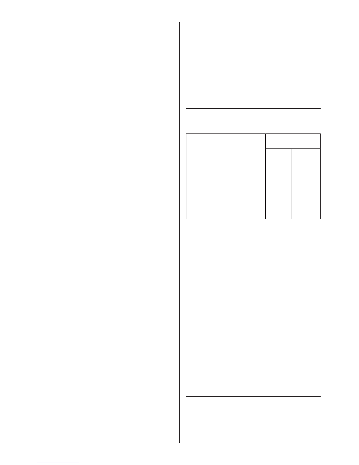
12. DECLARACIÓN DE LOS NIVELES
DE EMISIÓN DE RUIDO
Magnitudes Acústicas de Condiciones de
Emisión de ruido funcionamiento
Vacío Carga
Nivel de presión acústica, de
emisión continuo equivalen-
te ponderado A, en el puesto
de trabajo Lp
A
84 dB(A) 94 dB(A)
Nivel de potencia acústica
ponderado A, emitido por la
máquina Lw
A
92 dB(A) 104dB(A)
Datos correspondientes a valores medidos
Constante de declaración K= 4 dB(A)
Normas utilizadas en la medida, determinación y
declaración del ruido:
ISO 7960 (Anexo A), ISO/DIS 11202 (prEN 31202),
ISO/DIS 3746 (prEN23746) y pr EN 1870-1
Los valores dados son sólo de emisión y no necesariamente niveles que permitan trabajar con seguridad.
Aunque existe una correlación entre los niveles de
emisión y los de exposición éstos no pueden ser
utilizados de manera able para determinar si son
necesarias medidas de precaución suplementarias.
Los parámetros que inuyen en el nivel real de exposición comprenden la duración de la exposición, las
características del taller, otras fuentes de ruido, etc.,
es decir el número de máquinas y otros procesos
adyacentes.
Además, los niveles de exposición admisibles pueden
variar de un país a otro. Sin embargo esta información
permite al usuario de la máquina hacer una mejor
evaluación de riesgos.
13. GARANTIA
Todas las máquinas VIRUTEX tienen una garantía
válida de 12 meses a partir del día de suministro,
quedando excluidas todas las manipulaciones o daños
ocasionados por manejos inadecuados o por desgaste
natural de la máquina. Para cualquier reparación
Page 7

7
puede dirigirse a un Servicio Ocial de Asistencia
Técnica VIRUTEX.
En la inquietud continua por la mejora y actualización
de sus productos, VIRUTEX se reserva el derecho de
modicarlos sin previo aviso.
TILTABLE MITRE SAW
With table top: Models TM72C and TM73C
Without table top: Models TS72C and TS73C
IMPORTANT NOTE
ATTENTION! Prior to using the machine, please read
carefully the GENERAL SAFETY INSTRUCTIONS
LEAFLET enclosed with the documentation.
Please keep the aforementioned LEAFLET and this MANUAL in a safe place for future reference purposes.
1. TECHNICAL FEATURES
Model...........................................TM72C and TS72C
Version..................................................Single-phase
Motor.......................................................50 or 60 Hz
Power consumption......................................1,200 W
Service........................................................12/48 min
No-load speed (50 Hz)..............................3,000/min
Saw blade diameters.................................300x30 mm
Model...........................................TM73C and TS73C
Version..................................................Three-phase
Motor.......................................................50 or 60 Hz
Power consumption......................................1,300 W
Service........................................................12/48 min
No-load speed (50 Hz)...............................3,000/min
Saw blade diameters.................................300x30 mm
Turntable
Can be swivelled both right and left up to 45° with a
xed lock position at 0°, 15°, 22°, 30', 30° and 45°. It
also allows xation at intermediate degree settings.
Tiltable head
Swivelling from 90° to 45° as against the base and in any
position of the turntable, from 0° to 45° to the left.
Dimensions of the machine.....................(See Fig. 3)
Dimensions of the packing..............720x600x530 mm
Approximate weight
(without packing)...........30 kg (models with table top)
26 kg (models without table top)
2. MAXIMUM CUT CAPABILITIES
Cut at 0° x 90° (Fig. 9). See drawing A......80x150 mm
Cut at 0° x 45° (Fig. 12). See drawing B.....65x150 mm
Cut at 45° x 90° (Fig. 15). See drawing C...80x103 mm
Cut at 45° x 45° (Fig. 16). See drawing D....63x 60 mm
Cut on table top. See drawing E (*)...........max 35 mm
(*) for Models TM72C and TM73C only.
3. UNPACKING THE MACHINE
You will nd the following elements inside the packing
case (Fig. 1):
For models TM72C and TM73C:
- Cut-off machine, according to the model
- Table square assembly
- Wood setting stop set
- Exhaust adapter
- Set of Allen wrenches 8mm
- Operation instructions and documentation
For models TS72C and TS73C:
- Cut-off machine, according to the model
- Wood setting stop assembly
- Exhaust adapter
- Set of Allen wrenches 8mm
- Operation instructions and documentation
For transport purposes, the machine head is locked in
its lower position. During unpacking, merely hold the
machine by the sides of the lower base and remove
it from the box. It is advisable for this operation to be
carried out by at least two people.
4. PREPARATION AND SETUP
ATTENTION! Make sure that the machine is unplugged
from the mains prior to carrying out any repairs or
maintenance operations on it.
4.1 INSTALLATION
For using the machine at a xed spot, we recommend
its being coupled to a table or work bench at a height
of around 90 cms and using the holes A provided
on the base (Figs. 2 and 3). We recommend our
TRANSPORTABLE WORKING TABLE accessory
(Ref. 5800100)
The three-phase models of mitre saws have a factory
setting of 380 V. The user must implement a plug
suitable for his installations on the supply cable, but
always with a minimum capacity of 16 Amperes. In
addition, once the machine is connected to the mains,
it is essential to check that the blade turns in the direction indicated on the disc or the outside cover of the
machine. If the direction is not the same, the order
of two of the cables in the assembled mains supply
plug must be inverted.
This machine is foreseen exclusively for indoor work,
due to which it should not be placed in very damp
areas nor exposed to rain.
4.2 UNLOCKING THE HEAD
The machine leaves the factory with the head locked in
the correct position for transport. To unlock it, proceed
to press gently downwards on the handle (B) while
at the same time pressing on the orange colour lever
and pulling the knob "E" (Fig. 4) which is located at
the rear of the right hand side of the head, Turn it
90° until it comes to its normal resting position. Then
accompany the machine in its upwards movement to
its normal resting position.
ENGLISH
Page 8

8
4.3 TESTING
Before connecting the machine to the mains, check
that the protectors and safety mechanisms are working properly.
At the same time, make sure that the frequency and
voltage of the mains corresponds to what is indicated
on the machine's name plate. Never connect the cut-off
machine to a power supply system that is not supplied
with good earthing, with the corresponding differential
protection and with a device for guarding against short
circuits caused by overload (e.g. fuses)
In the event of using an extension cord, make sure
that the cross section of the conductors is appropriate
to the length thereof and to the rated current of the
machine itself.
4.4 CHANGING THE VOLTAGE
For Models TM73C and TS73C only. The machines
leave the factory prepared for three-phase 380 V. In
the event of your wishing to change the connections
for a three-phase 220 V, we recommend the change
being made at ONE OF VIRUTEX'S Ofcial Technical
Support Centres.
5. SAFETY ELEMENTS
5.1 START-STOP SWITCH
The cut-off machine has a green button on its handle
to start the machine and, next to it, a red one which
causes the machine to stop immediately.
In the cut-off mode, with the turntable head raised in
its resting position (Fig. 7), press the green button
"H" and use the handle lever, lowering it gently to
make the cut.
ATTENTION!
Do not start to cut until the blade has reached the full
rotation speed.
Do not force the saw. Total or partial lock of the motor
can cause serious breakdowns.
5.2 PROTECTION AGAINST ACCIDENTAL
START-UPS DUE TO POWER FAILURES
The machine has a system which, in the event of a
voltage dip or power failure, cuts out the circuit and
prevents the machine from starting up accidentally.
To start the machine up again, the green start-up
button has to be pressed anew.
5.3 SAW BLADE PROTECTIVE COVER
In its resting position, the saw blade is totally covered
by protective covers and the machine remains xed
in this position The protective cover "J" covers the
whole saw blade and automatically pulls back when
the turntable swivels ready for cutting (Fig. 8).
ATTENTION! Make sure the saw blade is totally
covered by the protective covers when the machine
is in the resting position. Always keep the protective
covers in good condition.
5.4 TABLE TOP PROTECTIVE COVERS
In the models with a table top, TM72C and TM73C,
the machine is equipped with a protector "K" (Fig. 8)
which covers the accessible part of the blade and only
allows the material that is to be cut to enter and pass
through. Similarly in these models, and when the cuts
are being made on the table top, an additional protec-
tive cover should be placed under the table in order to
avoid any possible contact with the disk.
There is also a top "L" ruler which serves as a cutting
guide on the table and as a total saw blade protective
cover in the cut-off mode.
6. ADJUSTMENTS
ATTENTION! Make sure that the machine is unplugged from the mains prior to carrying out any kind
of manipulation.
The cut-off machine leaves the factory perfectly ad-
justed. Nevertheless, the following mechanisms are
provided for later adjustments.
6.1 ADJUSTMENT OF THE HINGED HEAD
To adjust the saw blade at 90° as against the machine
body (0° on the indicator situated on the rear hinged
section of the machine) (Fig. 11), use a checking square
between both and proceed as follows:
Loosen handle P and nut Z (Fig. 10) and correct any
possible deviation using the A1 Allen stud.
Similarly, the hinged head can be adjusted at 45° as
against the table top (45° on the rear hinged section of
the machine) in this case by pressing on the B1 stud once
the corresponding nut (Fig. 10) has been loosened.
6.2 ROTATING PLATE ADJUSTEMENT
The machine is provided with an automatic lock at 0°,
15°, 22.5°, 30° and 45° and therefore, rarely requires
resetting at these positions. If necessary, to adjust the
saw blade at 90° can be positioned perpendicular to
the straight edge as follows: Set the machine plate
to 0° (set table indicator S (Fig. 14) to 0° on the plate
scale), place a square between the base ruler and
the saw blade, loosen screws C1 (Fig. 13) which
hold trigger R and move the trigger to correct for
the deviation between the ruler and the cutting disc.
Retighten the screws.
6.3 SETTING THE MAXIMUM CUTTING DEPTH
The cutting depth stop is set by adjusting nut and stud
D1 (Fig. 10) and should be reset whenever the saw
disc is changed or sharpened.
ATTENTION!
-Make sure that the saw does not touch the bottom of
the plate once the lowering stop is set.
-Replace any damaged or broken plate cover.
6.4 SETTING THE SEPARATOR BLADE
For cuts made on top of the upper table (TM72C and
TM73C models only), the machine is equipped with a
separator blade which prevents the cut from closing
on the wood once the saw disc is passed. The blade
position should be set according to the diameter and
condition of the saw disc. To set, do the following:
Page 9

9
-Unscrew screws K1 and remove cover M1 (Fig. 8).
-Loosen screws N1 (Fig. 6), adjust the blade and
retighten the screws which hold it, then remount the
cover M1.
ATTENTION!
-The space between the saw blade teeth and the
separator blade should never exceed 5 mm (Fig. 6).
-Use only saw blades with a body thinner than the
blade thickness (2.5 mm) and teeth thicker than this
thickness.
7. CUTTING OFF APPLICATIONS,
REQUIRED WORKING CONDITIONS
This machine model efciently and accurately cuts off
wood and plastic workpieces, and aluminium prole.
ATTENTION!
-It is essential to use clamps (see Section 10) for
cutting off of aluminium prole, plastic and long
workpieces (Fig. 24).
-Do not start cutting until the blade is spinning at its
full speed.
7.1 CUTTING AT 0° x 90°
Set the rotating plate to 0° using the S index on the
table and the head to 0° using the index on the rear
swivelling side (Fig. 9 and 11).
7.2 CUTTING AT 0° x 45°
Set the rotating plate to 0° using the index on the table,
loosen knob P and set the head to 45° with the index
on the rear swivelling side (Fig. 11 and 12).
Retighten knob P at the setting selected.
7.3 CUTTING AT 45° x 90°
With the head in a vertical position, raise trigger R
(Fig.13) and turn the plate until index S of the table
indicates 45° or any other intermediate angle desired
(Fig. 13 and 14).
7.4 CUTTING AT 45° x 45°
Raise trigger R (Fig. 13) and turn the left plate to 45°.
Release the trigger to lock the machine. To set the plate
at intermediate settings without a xed lock, tighten
knob G1 (Fig. 16) at the desired setting. Loosen knob
P (Fig. 10) and swivel the head to 45° or to any intermediate angle desired and retighten the knob.
ATTENTION!
-Do not turn the plate towards the right with the head
swivelled as the machine is equipped with an internal
mechanism that prevents this movement.
-Make sure that the swivelling head is perfectly set in
position when chamfering.
7.5 FINE PRECISION CUTS
When cutting off thin or brittle wood, the use of an
auxiliary wood ruler is recommended (Fig. 17). The
machine is equipped with a ruler M (Fig. 7) for this
purpose, as well as nuts N with M4 threads to hold the
auxiliary ruler. This provides a proper support base in
the cutting area of the saw blade in order to prevent
the material from breaking and cutting residue from
ying out behind the saw blade.
7.6 CUTTING WORKPIECES IN SERIES
To perform repetitive cuts of a xed length, mount the
adjustable side stop assembly F (Fig. 2) on the ruler
guide on the desired side of the machine, adjust and
set its position with knob G. The stop for the length to
be cut can be set with the knobs on this assembly.
8. CUTTING ON THE UPPER TABLE,
REQUIRED WORKING CONDITIONS
(TM72C and TM73C models only)
ATTENTION! Only wood or plastic can be cut on the
upper table. Do not use for aluminium or proles.
To use the machine in this cutting mode, the machine
must rst be tted with the lower screen D (Fig. 5) to
prevent any accidental contact with the saw disc below
the table. Fit the right-hand side of the fairing on to
the machine rst, followed by the left-hand side. Once
both parts are tted on, proceed to join them using
closure clamps D1 (Fig. 5). Then lock the machine
in transport setting with knob E (Fig. 4), making sure
that the cutting screen is perfectly tted and stationary. Loosen knob Y, remove the upper ruler U (Fig.
4) that houses the blade protective cover and use it
as a side cutting guide, locking it at the desired blade
distance (Fig. 20).
Use the upper ruler as a side cutting guide to obtain
a maximum strip width of 148 mm. This ruler contains
a slit on the side which has two nuts V (Fig. 18) and
can be used to hold a wooden strip that reaches the
vertical axis of the middle of the saw blade. It is a
good idea to mount this strip (Fig. 20) when cutting
short workpieces (dowelling and stubs) since, with
this kind of cut, the cut piece is held by the rotation of
the blade which could cause the piece to be expelled
forcefully as it exits the blade centre if there is insuf-
cient clearance at the outlet.
Use the adjustable square X (Fig. 19) to cut any angle
by placing the square in the guides on the table.
The blade outlet with respect to the table can be
adjusted by loosening knob T (Fig. 4) and raising or
lowering the table to the desired cutting height, making
sure that the blade exceeds the material to be cut by
the height of the tooth. Tighten knob T tightly at the
selected cutting height.
Once cutting on top of the table has been nished,
place the upper ruler U once again in its protective
position, prior to using the cutting off function of the
machine.
ATTENTION!
-Do not use the upper table without putting the suction
fairing in place.
-Never work without the upper protective cover.
-Replace the separator blade when it is worn.
-Do not use the machine to make grooves or blind cuts.
-Use the pusher Z1 (Fig. 18) to feed the workpiece
through the saw blade.
-Use the upper blade protective cover correctly.
Page 10
10
-Make sure that the swivelling head is perfectly stationary in its position when working with the upper table.
-Make sure that the upper table is rmly positioned at
the desired cutting height.
9. EXHAUST OUTLET
On the rear side of the machine a nozzle (diameter 80
mm) is provided, which can be connected to a hose
for tting to an industrial vacuum cleaner or other
type of central vacuum system to collect chips and
sawdust. Furthermore, the machine is also equipped
with a Vacuum Adaptor that allows it to be connected
to most vacuum models available on the market.
Connection to ours vacuums AS182K, AS282K is
especially recommended.
For work on the upper table, and in addition to the
connection mentioned above, the fairing is provided
with a nozzle D2 (Fig. 5) to which the standard dust
collector attachment (Ref. 6446073) must be connected for perfect collection of the shavings.
It is recommended that the machine always be connected to a chip and sawdust collection device.
10. OPTIONAL ACCESSORIES
Item No. 7240188: 48Z hard metal saw blade (for
wood)
For mitring jobs or for cutting strips of wood or chip-
board, we recommend this specially designed saw
disc. It enhances mitre saw performance and prolongs
its lifespan.
Item No. 9040069: HM Saw blade 72Z (for aluminium)
Item No. 5800100: Transportable working table
Item No. 7500092: Set of two clamps (Fig. 24). Essential
for cutting off of aluminium and plastics.
Item No. 8200100: Industrial vacuum cleaner AS182K
Item No. 8200200: Industrial vacuum cleaner AS282K
11. MAINTENANCE AND CLEANING
ATTENTION! Make sure that the unit is disconnected
from the electric mains before handling in any way.
11.1 CHANGING THE SAW BLADE
Place the swivelling head in the rest position for the
cutting off mode. For models TM72C and TM73C,
use knob T (Fig. 4) to raise the upper table as much
as possible. Remove the screws K1 and take off the
cover M1 (Fig. 8). Place one of the Allen wrenches
provided in screw E1 (Fig. 21) which holds the blade
and the other in the housing located on rear cover F1
(Fig. 22). Loosen screw E1 in the clockwise direction.
Once the saw blade is loosened, remove this screw
and the plate holding the blade, separate it from its
shaft and raise it slightly to free it from its protective
covers. It can then be removed.
Perform the reverse operation to mount a new saw
blade, placing the arrow of the blade in the same direction as the one on the outside cover of the rocker arm.
Make sure that all the housings of the elements to be
mounted are very clean and that the outer bridge plate
ts perfectly into the offset at the end of the shaft.
In models TS72C and TS73C, loosen screws "A" (Fig.
25) and move the upper protector upwards. Then
proceed to change the blade, following the same
instructions as for models TM72C and TM73C.
ATTENTION!
- Before using the machine once more, ensure that all protectors are in position and in a perfect state of repair.
-Make sure that the new saw blade mounted is the
same diameter as the one replaced.
-Do not use saw blades that are damaged or warped.
-Select the saw blade type on the basis of the material to be cut.
-Use only saw blades that meet the specications
contained in this manual. Always make sure that
the blade body is thinner than the thickness of the
keel (2.5 mm) and that the teeth are thicker than this
thickness.
11.2 MOTOR BRAKE
The machine is equipped with an electromechanical brake module that ensures that the saw blade is
completely stopped within ten seconds after the stop
button (red button) is activated.
For your personal safety, we recommend that the Ofcial VIRUTEX Technical Support Service be contacted
for replacement of the braking device whenever this
time appears to be longer.
For your safety, we recommend that when you observe
that the stoppage time of the blade is higher than this
margin due to the pads being worn down, you contact
an Ofcial VIRUTEX Technical Support Service in
order to replace them.
We recommend that you check the braking time after
every 200 hours of work.
11.3 LUBRICATION AND CLEANING
The unit, as delivered, has been completely lubricated
in the factory and does not require any special care
through-out its useful life. Periodic cleaning and greasing
of the mechanical articulations with oil is sufcient.
It is important to carefully clean the machine after each
use with dry compressed air.
The power supply should always be kept in perfect
conditions for use.
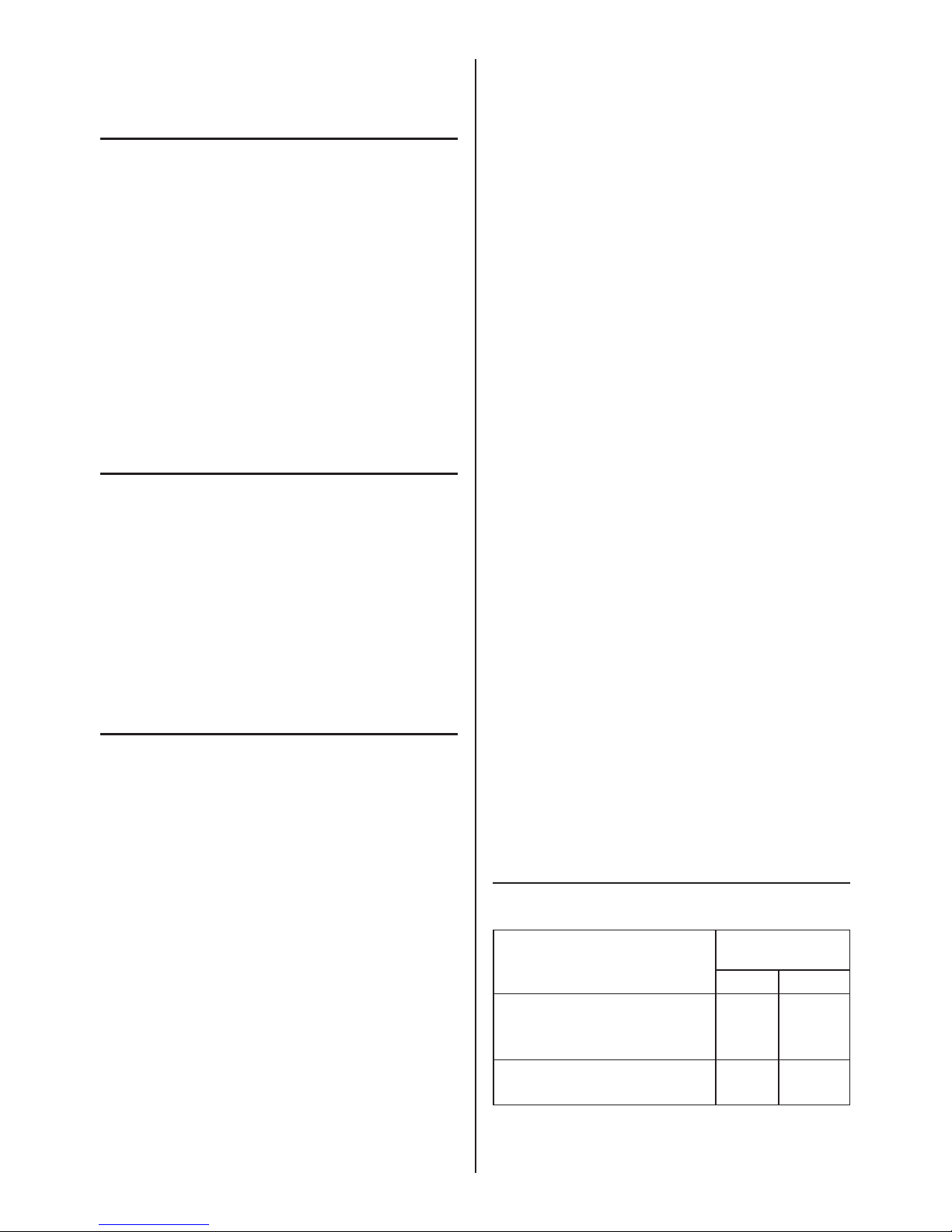
12. STATEMENT OF NOISE EMISSION LEVELS
Acoustic magnitudes of Operating
noise emission conditions
No-load Loaded
Acoustic pressure level, of
equivalent weighted continuous
emission A1 in workplace LpA 84dB(A) 94dB(A)
Weighted acoustic power level
A, emitted by machine Lw
A
92dB(A) 104dB(A)
Data corresponding to measured values.
Statement constant K= 4 dB(A)
Page 11

11
Standards used for measurement, determination and
declaration of noise levels:
ISO7960 (Appendix A), ISO/DIS 11202 (pnEN 31202),
ISO/DIS 3746 (pr EN23746) and pr EN 1870-1.
The values given are for emission only and do not
necessarily indicate safe working levels.
Although there is a correlation between noise emis-
sion and exposure levels, these cannot be reliably
used to determine if additional preventive steps
are required. Parameters which may affect the true
exposure level include: duration of the exposure,
features of the workshop, other sources of noise, etc.,
i.e. the number of machines and other processes in
surrounding areas.
In addition, allowable exposure levels may vary between countries. Nevertheless, this information allows
the user to better evaluate the risks involved.
13. WARRANTY
All VIRUTEX machines are supplied with a valid
warranty of 12 months from the date of supply. Any
handling or damage caused by improper usage or
natural wear and tear of the machine are excluded.
For any repair, please contact your Ofcial VIRUTEX
Technical Support Service.
In its continued concern for improve and upgrade,
VIRUTEX reserves the right to change its products
without prior notice.
TRONÇONNEUSE INCLINABLE
Avec table supérieure: Modèles TM72C et
TM73C
Sans table supérieure: Modèles TS72C et TS73C
NOTE IMPORTANTE
ATTENTION: Avant d'utiliser la machine, lire attentivement la BROCHURE D'INSTRUCTIONS GENE-
RALES DE SECURITE jointe à la documentation
générale.
Conserver soigneusement cette BROCHURE ainsi que
ce MANUEL pour toute consultation ultérieure.
1. CARACTERISTIQUES TECHNIQUES
Modèle.............................................TM72C et TS72C
Version....................................................Monophasée
Moteur.....................................................50 ou 60 Hz
Puissance absorbée......................................1.200 W
Production................................................12/48 min.
Vitesse de rotation à vide (50 Hz)..........3.000 trs/min.
Diamètre lame de scie.............................300x30 mm
Modèle............................................TM73C et TS73C
Version....................................................Triphasée
Moteur....................................................50 ou 60 Hz
Puissance absorbée......................................1.300 W
Service.......................................................12/48 min.
Vitesse de rotation à vide (50 Hz)..........3.000 trs/min.
Diamètre lame de scie..............................300x30 mm
Plateau rotatif
Orientable à droite ou à gauche jusqu'à 45° avec
blocage xe sur les positions à 0°, 15°, 22° 30', 30°
et 45°. Il est en outre possible de le bloquer sur des
réglages en degrés intermédiaires.
Tête basculante
Basculable de 90° à 45° par rapport à la base et dans
toute position de rotation du plateau de 0° à 45° dans
le sens gauche de celui-ci.
Dimensions de la machine.......................Voir (Fig. 3)
Dimensions de l'emballage..............720x600x530 mm
Poids approximatif
(sans emballage........30 kg (modèles avec table sup.)
26 kg (modèles sans table sup.)
2. CAPACITES MAXIMALES DE COUPE
Coupe à 0°x90° (Fig. 9) Voir croquis A......80x150 mm
Coupe à 0°x45° (Fig.12) Voir croquis B....65x150 mm
Coupe à 45°x90°(Fig.15) Voir croquis C...80x103 mm
Coupe à 45°x45° (Fig. 16) Voir croquis D....63x60 mm
Coupe sur la table sup. Voir croquis E (*)...max 35 mm
(*) Uniquement pour les modèles TM72C et TM73C.
3. DEBALLAGE DE LA MACHINE
Vous trouverez dans l'emballage les pièces suivantes
(Fig. 1):
Pour les modèles TM72C et TM73C
- Tronçonneuse selon modèle
- Ensemble équerre de la table
- Ensemble butée de réglage du bois
- Adaptateur aspiration
- Jeu clés Allen c/c 8 mm
- Manuel d'Instructions et documentations diverses
Pour les modèles TS72C et TS73C
- Tronçonneuse selon modèle
- Ensemble butée de réglage du bois
- Adaptateur aspiration
- Jeu clés Allen entre faces 8 mm
- Manuel d'Instructions et documentations diverses
Pour le transport, la tête de la machine a été bloquée
dans sa position inférieure et donc, pour la déballer,
il suft de maintenir la machine par les côtés de la
base inférieure et de l'extraire de la caisse. Il est re-
commandé de procéder à cette opération avec deux
personnes au minimum.
4. PRÉPARATION ET MISE AU POINT
ATTENTION! S'assurer que la machine est déconnectée du réseau électrique avant de réaliser sur celle-ci
toute opération de préparation ou entretien.
4.1 INSTALLATION
FRANÇAIS
Page 12

12
Pour utiliser la machine à un poste xe, nous recommandons de la xer sur une table ou un établi à
une hauteur approximative de 90 cm au moyen des
orices A de la base (Fig. 2 et 3). Nous recommandons d'utiliser notre accessoire TABLE DE TRAVAIL
TRANSPORTABLE (Réf. 5800100).
Les modèles de tronçonneuse triphase sont connec-
tés d'origine pour une tension de 380 V, l'usager
devant mettre une prise de courant sur le câble
d'alimentation adaptée à son installation mais ayant
toujours une capacité minimale de 16 Ampères. De
plus, après avoir branché la machine sur le secteur,
il est indispensable de vérier si le sens de rotation
de la lame coïncide avec celui qui est indiqué sur le
disqué sur le disque ou sur le couvercle extérieur de
la machine. S'ils ne coïncident pas, il faudra inverser
le branchement de deux des phases sur la che de
prise de courant montée.
Cette machine a été exclusivement prévue pour tra-
vailler à l'intérieur et ne doit donc pas être exposée à
la pluie ou à des atmosphères très humides.
4.2 DEBLOCAGE DE LA TETE
La machine sort d'usine avec la tête bloquée dans la
position de transport. Pour la débloquer, exercer sur la
poignée une pression vers le bas tout en appuyant B
sur le levier orange et en tirant sur la poignée E (Fig.
4) située à l'arrière et à droite de la tête, en la faisant
tourner de 90° jusqu'à sa position de repos. Suivre
ensuite la machine dans son mouvement de montée
jusqu'à ce qu'elle soit bloquée en position de repos.
4.3 VERIFICATIONS
Avant de connecter la machine au réseau, s'assurer
du bon fonctionnement des protecteurs et des mécanismes de sécurité.
Vérier également que la fréquence et la tension
du réseau correspondent bien aux indications de la
plaque de caractéristiques de la machine. Ne jamais
connecter la tronçonneuse à un réseau d'alimentation
qui ne soit pas muni d'une bonne prise de terre et du
disjoncteur de protection correspondant, ainsi que
d'un dispositif de protection contre les courts-circuits
par surintensité (par exemple: fusibles).
Si on utilise une rallonge, vérier que la section des
conducteurs correspond à leur longueur et à l'intensité
nominale de la machine.
4.4 CHANGEMENT DE TENSION
Uniquement pour les modèles TM73C et TS73C. En
série, les machines sont prévues en usine pour une
tension triphasée de 380 V; si on désire changer les
connexions pour une tension triphasée de 220 V, il
est recommandé de faire procéder à ce changement
dans un Service Ofciel d'Assistance Technique
VIRUTEX.
5. ELEMENTS DE SECURITE
5.1 INTERRUPTEUR MARCHE-ARRET
On trouvera sur la poignée de la tronçonneuse un
bouton vert qui permet de mettre la machine en marche
et à côté de celui-ci un bouton rouge qui provoque
son arrêt immédiat.
Dans la modalité tronçonnage, avec la tête basculante
relevée en position de repos (Fig. 7), appuyer sur le
bouton vert H et actionner le levier de la poignée, en
faisant descendre lentement celle-ci pour réaliser
la coupe.
ATTENTION!
Ne pas procéder à la coupe avant que la lame ait
atteint sa pleine vitesse de rotation.
Ne pas forcer la scie. Tout blocage total ou partiel du
moteur peut provoquer d'importants dégâts.
5.2 PROTECTION CONTRE TOUTE MISE
EN MARCHE ACCIDENTELLE PAR
SUITE D'UNE COUPURE DE COURANT
La machine dispose d'un système qui, en cas de chute
de tension ou panne de l'alimentation en électricité,
interrompt le circuit et évite toute mise en marche
accidentelle de la machine.
Pour remettre la machine en marche, il est nécessaire
d'appuyer à nouveau sur le bouton vert du poussoir
de mise en marche.
5.3 PROTECTEUR DE LA LAME DE SCIE
En position de repos, la lame de scie est complètement recouverte par les protecteurs et la machine est
bloquée dans cette position. Le protecteur J couvre
toute la lame de scie et s’écarte automatiquement
lorsque la tête basculante se déplace pour réaliser
la coupe (Fig. 8).
ATTENTION! S'assurer que la lame de scie est
complètement recouverte par les protecteurs dans
la position de repos de la machine. Veiller à ce qu'ils
soient toujours en bon état.
5.4 PROTECTEURS SUPERIEURS
Pour les modèles à table supérieure TM72C et TM73C,
la machine dispose d'un protecteur K (Fig. 8) qui recou-
vre la partie accessible de la lame et laisse uniquement
entrer et passer le matériau à couper. D'autre part,
pour ces modèles de machines, lorsqu'on procède
à la coupe sur la table supérieure, il faut placer un
protecteur supplémentaire au-dessous de la table an
d'éviter tout contact éventuel avec le disque.
On dispose également d'une règle supérieure L qui sert
de guide de coupe sur la table et de protecteur total
de la lame dans la modalité de tronçonnage.
6. REGLAGES
ATTENTION! S'assurer que la machine est déconnectée du réseau électrique avant de procéder à une
manipulation sur celle-ci.
La tronçonneuse est parfaitement réglée en usine,
mais est cependant munie des mécanismes indiqués
ci-après pour des réglages ultérieurs.
6.1 REGLAGE DE LA TETE BASCULANTE
Pour régler à 90° la lame de scie par rapport à la table
Page 13

13
de la machine (0° sur l'indicateur en degrés situé à
la partie basculante arrière de la machine) (Fig. 11),
placer une équerre de vérication entre celles-ci et
procéder comme suit:
Desserrer la poignée P et l'écrou Z (Fig. 10) et corriger
toute déviation éventuelle grâce au goujon allen A1.
On peut également régler la tête basculante à 45°
par rapport à la table (45° sur l'indicateur en degrés
situé à la partie basculante arrière de la machine) en
agissant dans ce cas sur le goujon B1 après avoir
desserré l'écrou correspondant (Fig. 10).
6.2 REGLAGE DU PLATEAU ROTATIF
La machine dispose d'un blocage automatique à 0°,
15°, 22,5°, 30° et 45°, raison pour laquelle il n'y a pas
à la régler à nouveau souvent dans ces positions.
Si besoin est, pour ajuster à 90° la lame de scie par
rapport à la règle, placer le plateau de la machine
sur 0° (placer l'indicateur de la table S (Fig. 14) sur
0° de la graduation de l'échelle du plateau), placer
une équerre entre la règle de base et la lame de scie,
desserrer les vis C1 (Fig. 13) qui bloquent la gâchette
R et déplacer celui-ci jusqu'à ce que soit corrigée la
déviation entre la règle et le disque de coupe, puis
resserrer les vis.
6.3 REGLAGE DE LA PROFONDEUR
MAXIMALE DE COUPE
La profondeur maximale de coupe s'obtient en réglant
l'écrou et le goujon D1 (Fig. 10). Celui-ci devra être
réajusté chaque fois que l'on changera la lame de
scie ou qu'on l'affûtera.
ATTENTION!
- Vérier que la scie ne touche pas le fond du plateau
lorsque la butée de descente a été réglée.
- Changer le couvercle du plateau si elle est endommagée ou cassée.
6.4 REGLAGE DU COUTEAU DIVISEUR
Pour réaliser des coupes sur la table supérieure
(uniquement pour les modèles TM72C et TM73C),
la machine est munie d'un couteau diviseur qui évite
que la coupe réalisée dans le bois se referme lorsque
celui-ci a dépassé la scie. La position de ce couteau
doit être réglée en fonction du diamètre et de l'état
de conservation de la lame de scie. Pour le régler,
procéder comme suit:
- Dévisser les vis K1 et ôter le couvercle M1 (Fig. 8)
- Desserrer les vis N1 (Fig. 6), régler le couteau et
resserrer les vis qui le bloquent, puis remettre en
place le couvercle M1.
ATTENTION!
- La distance entre les dents de la lame de scie et
le couteau diviseur ne devra jamais dépasser 5 mm
(Fig.6).
- N'utiliser que des lames de scie dont le corps sera
plus n que l'épaisseur de la lame (2,5 mm) et dont la
largeur des dents sera supérieure à cette épaisseur.
7. APPLICATIONS DU TRONÇONNAGE
CONDITIONS D'UTILISATION PREVUES
Ce modèle de machine permet de tronçonner avec
efcacité et précision les pièces en bois, en plastique
et les prols en aluminium.
ATTENTION!
- Il est indispensable d'utiliser des presseurs (voir chapitre 10) pour le tronçonnage des prols en aluminium,
en plastique et des pièces longues (Fig.24).
- Ne commencer la coupe que lorsque la lame a atteint
sa pleine vitesse de rotation.
7.1 COUPE A 0° x 90°
Placer le plateau rotatif sur 0° d'après le repère S de
la table et la tête à 0° d'après le repère de la partie
basculante arrière (Fig. 9 et 11).
7.2 COUPE A 0° x 45°
Placer le plateau rotatif à 0° d'après le repère de la table
et, en desserrant la poignée P, placer le tête à 45° par
rapport au repère de la partie arrière basculante ou à
l'angle intermédiaire désiré (Fig. 11 et 12).
Resserrer la poignée P dans la position choisie.
7.3 COUPE A 45° x 90°
Avec la tête en position verticale, soulever la gâchette
R (Fig. 13) et faire tourner le plateau jusqu'à ce que
le repère S de la table indique 45° ou tout autre angle
intermédiaire désiré (Fig. 13 et 14).
7.4 COUPE A 45° x 45°
Soulever la gâchette R (Fig. 13) et faire tourner le
plateau vers la gauche jusqu'à 45°, relâcher la gâchette
pour bloquer la machine. Pour bloquer le plateau sur
des graduations intermédiaires sans blocage xe,
serrer la poignée G1 (Fig. 16) sur la position choisie.
Desserrer la poignée P (Fig. 10) et rabattre la tête
à 45° ou tout autre angle intermédiaire désiré puis
resserrer la poignée.
ATTENTION!
- Ne pas faire tourner le plateau vers la droite lorsque
la tête est basculée, car la machine comporte un mécanisme interne qui empêche ce mouvement.
- S'assurer que la tête basculante est parfaitement
bloquée sur sa position lorsqu'on biseaute.
7.5 COUPES FINES DE PRECISION
Si on doit réaliser des tronçonnages sur des bois min-
ces ou fragiles, il est recommandé d'utiliser une règle
auxiliaire en bois pour y procéder (Fig. 17). A cet effet,
la machine est munie sur la règle M (Fig. 7) des écrous
N à letage M4 pour le blocage de la règle auxiliaire,
ce qui permet d'avoir une bonne base d'appui dans
la zone de support de la lame de scie, de manière à
éviter toute rupture éventuelle du matériau ou que les
restes de la coupe soient violemment expulsés à la
partie arrière de la lame de scie.
7.6 COUPES DE PIECES EN SERIE
Pour réaliser des coupes répétées de longueur xe,
monter l'ensemble butée latérale réglable F (Fig. 2)
Page 14

14
sur le guide de la règle du côté désiré de la machine
et régler et bloquer sa position à l'aide de la poignée
G. Le réglage de la butée à la longueur à couper
se réalise à l'aide des poignées dont est muni cet
ensemble.
8. COUPE SUR TABLE SUPERIEURE
CONDITIONS D'UTILISATIONS PREVUES
(Uniquement pour les modèles TM72C et TM73C)
ATTENTION! On ne peut couper sur la table supérieure
que du bois ou du plastique, ne jamais l'utiliser pour
couper de l'aluminium ou des prols. Pour utiliser la
machine dans cette modalité de coupe, placer d'abord
sur la machine le carénage inférieur D (Fig. 5) qui
évite tout contact accidentel avec la lame de scie
au-dessous de la table. Pour ce faire, emboîter tout
d'abord la partie droite du carénage sur la machine
et ensuite, la partie gauche. Quand les deux parties
sont emboîtées, les assembler avec les goupilles de
fermeture D1 (Fig. 5). Bloquer ensuite la machine
en position de transport au moyen de la poignée E
(Fig. 4), en vériant que le carénage est parfaitement
emboîté et immobilisé. Desserrer ensuite le boulon
Y, ôter la règle supérieure U (Fig. 4) qui enferme le
protecteur de la lame et l'utiliser en tant que guide
latéral de coupe en le bloquant à la distance voulue
de la lame (Fig. 20).
Si on utilise la règle supérieure comme guide latéral de
coupe, on dispose d'une largeur de bande maximale de
148 mm. Cette règle comporte sur le côté une rainure
qui comprend deux écrous V (Fig. 18) destinés à xer
une baguette en bois qui atteigne l'axe vertical du
centre de la lame de scie. Il convient de mettre cette
baguette en place (Fig. 20) pour procéder à la coupe
des pièces de petite longueur (blocs et pavés de bois)
car, pour ce type de coupe, si la pièce coupée ne trouve
pas lors de sa sortie du centre de la lame un certain
jeu, elle est retenue par la rotation de la lame ce qui
peut provoquer son expulsion incontrôlée.
Si on utilise l'équerre réglable X (Fig. 19), on pourra
couper à n'importe quel angle en plaçant l'équerre sur
les guides placés sur la table.
On peut régler la hauteur de la lame par rapport à la
table en desserrant la poignée T (Fig. 4) et en faisant
monter ou descendre la table à la hauteur de coupe
désirée, en veillant à ce que la lame ne dépasse
du matériau à couper que de la hauteur des dents.
Serrer fermement la poignée T à la hauteur de coupe
sélectionnée.
Une fois terminé le travail de coupe sur la table, placer
à nouveau la règle supérieure U sur sa position de
protection avant d'utiliser la machine pour sa fonction
de tronçonnage.
ATTENTION!
- Ne pas utiliser la table supérieure sans monter le
carénage d'aspiration.
- Ne jamais travailler sans le protecteur supérieur
- Remplacer le couteau diviseur lorsqu'il est usé
- Ne pas utiliser la machine pour effectuer des rainures
ou des coupes aveugles.
- Utiliser le poussoir Z1 (Fig. 18) pour déplacer la pièce
lorsqu'elle passe par la lame de scie.
- Utiliser correctement le protecteur supérieur de la
lame.
- S'assurer que la tête basculante est parfaitement
bloquée dans sa position lorsqu'on travaille avec la
table supérieure.
- S'assurer que la table supérieure est fermement
bloquée à la hauteur de coupe désirée.
9. SORTIE D'ASPIRATION
La machine est munie à la partie arrière d'une tuyère
de 80 mm de diamètre, ce qui permet de la connecter
à un tuyau exible qui peut être relié à son tour à un
aspirateur industriel ou tout autre système d'aspiration
centralisé pour le ramassage des copeaux et de la
poussière. On a également prévu dans l'équipement
de la machine un adaptateur d'aspiration permettant
de la connecter à la majorité des modèles d'aspira-
teurs actuels sur le marché. Nous recommandons tout
particulièrement de la connecter à notres aspirateurs
AS182K, AS282K.
Pour le travail sur la table supérieure, en plus de faire
la connexion qui précède, il faut connecter l'accouplement d'aspiration standard (Réf. 6446073) sur
la buse D2 (Fig. 5) du carénage, pour une parfaite
évacuation des copeaux.
Il est conseillé de toujours connecter la machine à
un dispositif de ramassage de la poussière et des
copeaux.
10. ACCESSOIRES EN OPTION
Réf. 7240188: Lame de scie 48Z en métal dur (pour
bois)
Pour les travaux de tronçonnage et de coupe de
bandes de bois ou d'aggloméré, nous conseillons
cette lame de scie au design spécial car il améliore
les performances de coupe de la tronçonneuse et
prolonge sa durée de vie.
Réf. 9040069: Lame de scie 72Z en métal dur (pour
alumimium)
Réf. 5800100: Table de travail transportable.
Réf.7500092: Jeu de deux presseurs (Fig. 24). In-
dispensable pour le tronçonnage de l'aluminium et
du plastique.
Réf. 8200100: Aspirateur industriel AS182K.
Réf. 8200200: Aspirateur industriel AS282K.
11. ENTRETIEN ET NETTOYAGE
ATTENTION! S'assurer que la machine est déconnectée du réseau électrique avant de procéder à
toute manipulation.
11.1 REMPLACEMENT DE LA LAME DE SCIE
Placer la tête basculante en position de repos dans
la modalité tronçonnage. Pour les modèles TM72C
et TM73C relever au maximum la table supérieure
à l'aide de la poignée T (Fig. 4). Enlever les vis K1
et retirer le couvercle M1 (Fig. 8). Introduire l'une
des clés allen de service dans la vis E1 (Fig. 21) qui
Page 15

15
bloque la scie et l'autre dans le logement prévu dans
le couvercle arrière F1 (Fig. 22). Desserrer la vis E1
dans le sens des aiguilles d'une montre. Lorsque la
lame de scie est desserrée, enlever cette vis et le
plateau de xation de la lame, l'extraire de son axe et
la soulever un peu pour la dégager de ses protecteurs,
on pourra ensuite l'extraire.
Procéder à l'inverse pour monter une nouvelle lame
de scie, orienter sa èche dans le même sens que
celle se trouvant sur le couvercle extérieur du bras
basculant, vérier que les sièges des éléments à
monter sont parfaitement propres et s'assurer que le
plateau de blocage extérieur s'emboîte parfaitement
dans les découpes de l'extrémité de l'axe.
Sur les modèles TS72C et TS73C, dévisser les écrous
"A" (Fig. 25) et déplacer le protecteur supérieur vers le
haut, ensuite changer la lame en suivant les mêmes instructions que pour les modèles TM72C et TM73C.
ATTENTION!
- Avant de réutiliser la machine, vérier que toutes les
protections sont bien à leur place et en parfait état
pour être utilisées.
- S'assurer que la nouvelle lame de scie montée est
du même diamètre que la précédente.
- Ne pas utiliser de lames de scie endommagées ou
déformées.
- Sélectionner les lames de scie en fonction du matériau à couper.
- N'utiliser que des lames de scie respectant les caractéristiques indiquées dans ce manuel et, de toutes
façons, s'assurer que le corps de la lame est moins
épais que le moyeu (2,5 mm) et qu'à son tour la largeur
des dents est supérieure à l'épaisseur de celui-ci.
11.2 FREIN MOTEUR
La machine est munie d'un frein électromécanique
qui permet que le temps qui s'est écoulé à partir du
moment où on appuie sur le poussoir d'arrêt (bouton
rouge) jusqu'à complète immobilisation de la lame de
scie soit inférieur à dix secondes.
Pour votre sécurité, nous vous recommandons, si vous
observez que le temps d'arrêt de la lame dépasse
ce délai à cause de l'usure des plaquettes, de vous
adresser à un Service Ofciel d'Assistance Technique
VIRUTEX pour les remplacer.
Il est recommandé de vérier le temps de freinage
toutes les 200 heures de travail.
11.3 GRAISSAGE ET NETTOYAGE
La machine est livrée complètement graissée en usine,
et n'exige aucun soin spécial pendant sa vie utile; il
suft de nettoyer et graisser périodiquement avec de
l'huile les articulations mécaniques.
Veiller à toujours nettoyer soigneusement la machine
après utilisation à l'aide d'un jet d'air sec.
Veiller à ce que le câble d'alimentation soit toujours
en parfait état d'utilisation.
12. DECLARATION DES NIVEAUX
D'EMISSION DE BRUIT
Valeur acoustique de Conditions de
l'émission de bruit fonctionnement
A vide
En charge
Niveau de pression acoustique,
d'émission continue équivalent
pondéré A, au poste de travail
Lp
A
84dB(A) 94dB(A)
Niveau de puissance
acoustique pondéré A, émis
par la machine Lw
A
92dB(A) 104dB(A)
Données correspondant aux valeurs mesurées
Constante de déclaration K = 4 dB(A)
Normes utilisées pour la mesure, la détermination et
la déclaration du bruit:
ISO 7960 (Annexe A), ISO/DIS 11202 (pr EN 31202),
ISO/DIS 3746 (pr EN23746) et pr EN 1870-1
Les valeurs indiquées concernent uniquement l'émission mais pas obligatoirement les niveaux permettant
de travailler en toute sécurité.
Bien qu'il y ait une corrélation entre les niveaux
d'émission et ceux d'exposition, ceux-ci ne peuvent
être utilisés de manière able pour la détermination
si des mesures de précaution supplémentaires sont
nécessaires. Les paramètres ayant une inuence
sur le niveau réel d'exposition comprennent la durée
de l'exposition, les caractéristiques de l'atelier, les
autres sources de bruit, etc... c'est-à-dire le nombre
de machines et les autres processus voisins.
De plus, les niveaux d'exposition admissibles peuvent
varier d'un pays à l'autre. Cependant, cette information
permet à l'usager de la machine de faire une meilleure
évaluation des risques.
13. GARANTIE
Toutes les machines VIRUTEX sont garanties 12 mois
à partir du jour de la livraison, à l'exclusion de toutes
manipulations ou dommages occasionnés par des
fausses manoeuvres ou l'usure naturelle de la machine.
Pour les réparations, s'adresser à un Service Ofciel
d'Assistance Technique VIRUTEX.
Etant donné ses recherches permanentes destinées
à améliorer et à actualiser ses produits, VIRUTEX se
réserve le droit de les modier sans avis préalable.
GEHRUNGSSÄGE
Mit Obertisch: Modelle TM72C und TM73C
Ohne Obertisch: Modelle TS72C und TS73C
DEUTSCH
Page 16

16
WICHTIGER HINWEIS
ACHTUNG! Lesen Sie vor Inbetriebnahme der
Maschine das Faltblatt mit den «Allgemeinen Sicher-
heitshinweisen», das den Unterlagen der Maschine
beiliegt, aufmerksam durch.
Bewahren Sie die Sicherheitshinweise und diese
Bedienungsanleitung sorgfältig auf, so daß Sie später
gegebenenfalls nachschlagen können.
1. TECHNISCHE DATEN
Modell............................................TM72C und TS72C
Version..................................Einphasenwechselstrom
Betriebsspannung................................50 oder 60 Hz
Aufgenommene Leistung................................1200 W
Betriebszeit..................................................12/48 min
Leerlaufdrehzahl......................3000 U/min bei 50 Hz
Sägeblattabmessungen...........................300x30 mm
Modell...........................................TM73C und TS73C
Version........................................................Drehstrom
Betriebsspannung................................50 oder 60 Hz
Aufgenommene Leistung...............................1300 W
Betriebszeit.................................................12/48 min
Leerlaufdrehzahl......................3000 U/min bei 50 Hz
Sägeblattabmessungen............................300x30 mm
Drehteller
Nach rechts und links bis maximal 45° drehbar mit
Raststellungen bei 0°, 15°, 22° 30', 30° und 45°.
Darüber hinaus besteht die Möglichkeit zur Einstellung
von Zwischenwinkeln.
Schwenkkopf
Schwenkbar von 90° bis 45° gegenüber der Basis
sowie bei allen Stellungen des Drehtellers von 0° bis
45° linksdrehend gegenüber dem Teller.
Abmessungen der Maschine..................vgl. (Abb. 3)
Packmaß..................................720 x 600 x 530 mm
Zirkagewicht
(ohne Verpackung).........30 kg (Modelle mit Obertisch)
26 kg (Modelle ohne Obertisch)
2. MAXIMALE SCHNITTMAßE
Schnitt bei 0°x90° (Abb. 9) Vgl. Zeich. A...80x150 mm
Schnitt bei 0°x45° (Abb.12) Vgl. Zeich. B..65x150 mm
Schnitt bei 45°x90°(Abb.15) Vgl. Zeich.C...80x103 mm
Schnitt bei 45°x45° (Abb.16) Vgl. Zeich. D..63x60 mm
Schnitt auf dem Obertisch Vgl.Zeich. E (*)...max.35mm
(*) nur TM72C und TM73C
3. VERPACKUNG DER MASCHINE
Der Lieferumfang enthält (Abb. 1):
Modelle TM72C und TM73C
- Ablängmaschine (jeweiliges Modell)
- Baugruppe Tischlehre
- Baugruppe Einstellung Holzanschlag
- Anschluß für Absaugung
- Satz Innensechskantschlüssel 8 mm
- Bedienungsanleitung und weitere Unterlagen
Modelle TS72C und TS73C
- Ablängmaschine (jeweiliges Modell)
- Baugruppe Einstellung Holzanschlag
- Anschluß für Absaugung
- Satz Innensechskantschlüssel 8 mm
- Bedienungsanleitung und weitere Unterlagen
Zum Versand wird der Schwenkkopf in eingezogener
Stellung xiert, so daß es beim Auspacken ausreicht,
die Maschine seitlich an der unteren Grundplatte anzu-
heben und aus der Kiste zu nehmen. Wir empfehlen,
dazu mindestens zwei Personen heranzuziehen.
4. VORBEREITUNG UND HERSTELLEN
DER BETRIEBSBEREITSCHAFT
ACHTUNG! Stellen Sie vor jeder Vorbereitungs-
oder Wartungsmaßnahme sicher, daß die Maschine
stromlos ist.
4.1 INSTALLATION
Zum Betrieb der Maschine an einem festen Arbeitsplatz empfehlen wir, sie auf einer etwa 90 cm hohen
Arbeitsbank fest zu montieren. Dazu sind die Durchgangslöcher A in der Grundplatte vorgesehen (Abb.
2 und 3). Wir empfehlen dazu die Verwendung des
Zusatzkits zur Transportabler Arbeitstisch (Best.-Nr.
5800100).
Die dreiphasigen Gehrungssägemodelle sind ab Werk
für eine Spannung von 380 V eingestellt. Der Benutzer
hat am Netzkabel eine fÜr seine Anlage greeignete
Steckvorrichtung anzubringen, die aber auf jeden Fall
eine Mindestkapazität von 16 Amprere haben muß.
Nach Anschluß der Maschine ans Netz ist unbedingt
zu überprüfen, daß sich das Sägeblatt in die auf der
Scheibe oder der äußeren Abdeckung der Maschine
angegebene Richtung dreht. Ist dies nicht dr Fall,
müssen zwei der Phasen am montierten Stromstecker
umgekehrt angeschlossen werden.
Die Maschine ist ausschließlich zum Betrieb in Innenräumen vorgesehen. Sie darf weder Regen noch
Feuchtigkeit ausgesetzt werden.
4.2 SCHWENKKOPFLÖSEN
Die Maschine wird mit in Transportstellung xiertem
Schwenkkopf angeliefert. Um die Fixierung zu lösen,
drücken Sie den Griff B leicht nach unten. Gleichzeitig drücken Sie auf den orangefarbenen Hebel und
ziehen am Knauf E rechts hinten am Schwenkkopf
(Abb. 4). Dabei wird der Schwenkkopf um 90° in
seine Grundstellung gedreht. Dann die Hubbewegung
der Maschine weiterhin kontrollieren, bis sie in der
Grundstellung einrastet.
4.3. PRÜFUNGEN
Vor Anschluß der Maschine an das Stromnetz vergewissern Sie sich, daß Schutzvorrichtungen und
-mechanismen einwandfrei arbeiten. Stellen Sie auch
sicher, daß Spannung und Frequenz den Angaben
auf dem Typenschild der Maschine entsprechen. Die
Maschine immer nur an Steckdosen mit einwandfreien
Schutzleiterkontakten, Fehlerstromschutzschaltern
Page 17

17
und einem Schutz gegen Kurzschlüsse durch Übers-
tromstärken (z.B. Sicherungen) anschließen.
Verwenden Sie ein Verlängerungskabel, so vergewissern Sie sich, daß der Aderquerschnitt für diese Ka-
bellänge und die Nennstromaufnahme der Maschine
ausreichend ist.
4.4. ANDERE SPANNUNGEN
Nur TM72C und TS73C: Die Maschinen sind serien-
mäßig ab Werk für 380V Drehstrom vorbereitet. Wollen
Sie den Anschluß auf 220V Drehstrom ändern, so ist
es empfehlenswert, die Umstellung vom zugelassenen
Virutex-Kundendienst vornehmen zu lassen.
5. SICHERHEITSEINRICHTUNGEN
5.1 EINSCHALTER
Die Maschine hat an ihrem Griff einen grünen Eins-
chaltknopf. Daneben bendet sich ein roter Knopf zur
Sofortabschaltung. Beim Sägebetrieb, bei dem der
Schwenkkopf in die Ruheposition gehoben ist (Abb. 7),
den grünen Knopf H drücken und den Hebel am Griff
betätigen. Letzteren vorsichtig mit der Schnittbewegung nach unten bewegen.
ACHTUNG!
Mit dem Sägevorgang erst beginnen, wenn das Sägeblatt die volle Drehzahl erreicht hat.
Gefühlvoll mit der Säge umgehen. Vollständiges oder
teilweises Blockieren des Motors kann zu schweren
Schäden führen.
5.2 SCHUTZ GEGEN
UNBEABSICHTIGTES EINSCHALTEN
DURCH KURZSCHLUß DER NETZSPANNUNG
Die Maschine verfügt über eine Einrichtung, die bei
einem Spannungsabfall oder Ausfall der Stromversorgung den Stromkreis unterbricht und unbeabsichtigtes
Einschalten verhindert.
Um die Maschine nach einem Abschalten wieder in
Betrieb zu setzen, muß der grüne Einschaltknopf
erneut betätigt werden.
5.3 SCHUTZVORRICHTUNG AM SÄGEBLATT
In Grundstellung ist das Sägeblatt vollständig von
der Schutzvorrichtung verdeckt. Die Maschine ist
in dieser Position eingerastet. Die Schutzhaube J
bedeckt das gesamte Sägeblatt und fährt automatisch
zurück, wenn der Schwenkkopf für den Sägevorgang
bewegt wird. (Abb. 8)
ACHTUNG! Vergewissern Sie sich, daß in der Grundstellung das Sägeblatt vollständig von den Schutzvorrichtungen abgedeckt wird. Diese Vorrichtungen müssen
sich immer in einwandfreiem Zustand benden.
5.4 SCHUTZVORRICHTUNGEN OBEN
Die Modelle mit Obertisch (TM72C und TM 73C) haben
Schutzvorrichtungen K (Abb. 8), die den zugänglichen
Teil des Sägeblatts abdecken. Nur das Zuführen von
Schnittgut ist möglich.
Daneben ist bei diesen Modellen im Falle von Sägearbeiten auf dem Obertisch unter dem Tisch eine
zusätzliche Schutzvorrichtung anzusetzen, die jeden
möglichen Kontakt mit dem Sägeblatt unterbindet.
Auch bendet sich auf dem Tisch eine obere Schiene
L, die zur Schnittführung und als vollständiger Schutz
des Sägeblatts beim Schnitt dient.
6. EINSTELLUNGEN
ACHTUNG! Vergewissern Sie sich vor allen Arbeiten
an der Maschine, daß diese stromlos ist.
Die Maschine kommt fertig eingestellt ab Werk, sie
läßt sich jedoch im weiteren Betrieb in der unten
angegebenen Weise nachstellen.
6.1 EINSTELLEN DES SCHWENKKOPFS
Um das Sägeblatt auf 90° quer zum Tisch der Maschine
(0° oder an der Anzeige am hinteren schwenkbaren Teil
der Maschine, Abb. 11), einzustellen, eine Prüehre
zwischen beide Teile bringen und dann Handgriff P
und Mutter Z (Abb. 10) lösen und eine eventuelle
Abweichung mit der Innensechskant-Einstellschraube
A1 korrigieren. Sie können den Schwenkkopf genauso auch auf 45° zum Tisch einstellen. (45° an
der Winkelanzeige am hinteren schwenkbaren Teil
der Maschine). In diesem Fall verstellen Sie die
Einstellschraube B1, nachdem Sie die zugehörige
Feststellmutter gelöst haben (Abb.10).
6.2 EINSTELLEN DES DREHTELLERS
Die Maschine rastet selbsttätig bei 0°, 15°, 22,5°,
30° und 45° ein. Daher ist Nachstellen für diese
Positionen nur selten erforderlich. Erforderlichenfalls
zur Nachjustierung des Sägeblatts auf 90° relativ zur
Führungsschiene den Teller der Maschine auf 0° stellen
(die Drehwinkelanzeige des Tisches S (Abb.14) auf
0° der Winkelskala des Tellers lassen) und eine Lehre
zwischen die Grundschiene und das Sägeblatt bringen.
Anschließend die Fixierschrauben C1 der Sperrklinke
R (Abb. 13) lösen und diese verschieben, bis Schiene
und Sägeblatt uchten. Dann die Schrauben wieder
anziehen.
6.3 EINSTELLEN DER MAXIMALEN SCHNITTIEFE
Die maximale Schnittiefe wird bestimmt durch die
Einstellung der Mutter und der Einstellschraube D1
(Abb. 10). Diese Nachstellung ist nach jedem Sägeblattwechsel oder Schleifen erforderlich.
ACHTUNG!
- Nach Einstellen des unteren Endanschlags prüfen,
daß das Sägeblatt den Boden des Tellers nicht
berührt.
- Der Belag des Tellers ist auszuwechseln, sobald er
verschlissen oder beschädigt ist.
6.4 EINSTELLEN DES TEILMESSERS
Für Schnitte auf dem Obertisch (nur bei den Modellen
TM72C und TM73C) verfügt die Maschine über ein
Teilmesser, das den Abschluß des Schnittes im Holz
verhindert, sobald das Sägeblatt überragt wird. Die
Position des Messers ist entsprechend dem Durchmesser und Abnutzungsgrad des Sägeblatts einzustellen.
Page 18

18
Bei der Einstellung wie folgt vorgehen:
- Die Schrauben K1 herausschrauben und den Deckel
M1 abnehmen (Abb. 8).
- Die Schrauben N1 lösen (Abb. 6), das Messer in die
richtige Stellung bringen und die Befestigungsschrauben wieder festziehen. Dann den Deckel M1 wieder
montieren.
ACHTUNG!
- Der Abstand zwischen den Sägezähnen und dem Teil-
messer darf niemals größer als 5 mm sein. (Abb. 6)
- Nur Sägeblätter verwenden, deren Blatt dünner und
deren Schränkung breiter ist als die Messerstärke
(2,5 mm).
7. ANWENDUNGSBEREICH UND
VORGESEHENE ANWENDUNGSBEDINGUNGEN
DER ABLÄNGMASCHINE
Diese Maschine längt Holz, Plastik, und Aluminiumprole schnell und präzise ab.
ACHTUNG!
- Beim Schnitt von Aluminium- und Kunststoffprolen
sowie langen Werkstücken ist die Verwendung von
Klemmvorrichtungen (vgl. Abschnitt 10) unbedingt
erforderlich (Abb. 24).
- Mit dem Sägevorgang erst beginnen, wenn das
Sägeblatt volle Drehzahl erreicht hat.
7.1 SCHNITT BEI 0° X 90°
Den Drehteller mit Hilfe der Markierung S am Tisch
auf 0° und den Schwenkkopf mit Hilfe seiner hintenliegenden Anzeigevorrichtung (Abb. 9 und 11) ebenfalls
auf 0° einstellen.
7.2 SCHNITT BEI 0° X 45°
Den Drehteller mit Hilfe der Markierung am Tisch auf
0° stellen, den Handgriff P lösen, den Schwenkkopf
mit Hilfe seiner hintenliegenden Anzeigevorrichtung
auf 45° oder den gewünschten kleineren Winkel
einstellen (Abb. 11 und 12). Abschließend den Griff
P wieder festziehen.
7.3 SCHNITT BEI 45° X 90°
Den Schwenkkopf in senkrechte Stellung bringen
und die Sperrklinke R anheben (Abb. 13). Den Teller
drehen, bis die Anzeige S am Tisch auf 45° oder einem
beliebigen Zwischenwinkel (Abb. 13 und 14) steht.
7.4 SCHNITT BEI 45° X 45°
Die Sperrklinke R anheben (Abb. 13) und den Tisch
um 45° nach links drehen. Die Sperrklinke loslassen,
wodurch die weitere Drehung blockiert wird. Um
den Teller nichtrastend in einer Zwischenstellung zu
xieren, den Knauf G1 (Abb. 16) in der gewählten
Stellung festziehen. Den Griff P (Abb.10) lösen und
den Schwenkkopf auf 45° oder einen beliebigen Zwischenwinkel neigen. Den Griff P wieder festziehen.
ACHTUNG!
- Niemals den Teller nach rechts drehen, während
der Schwenkkopf geneigt ist. Die Maschine enthält
einen eingebauten Mechanismus, der diese Drehung
unterbindet.
- Vergewissern Sie sich, daß der Schwenkkopf beim
Anfasen absolut fest sitzt.
7.5 SAUBERE PRÄZISIONSSCHNITTE
Beim Sägen weicher oder zerbrechlicher Hölzer empfehlen wir die Verwendung einer Führungsschiene aus
Holz (Abb. 17). Dazu hat die Maschine an der Führung
M (Abb. 7) mehrere Muttern N mit M4-Gewinde zum
Aufsetzen von Zusatzführungen.
Auf diese Weise wird das Material im Arbeitsbereich
des Sägeblatt gut gestützt. Dadurch wird einerseits
Materialbruch verhindert und andererseits fallen keine
Sägereste hinter das Sägeblatt.
7.6 SERIENSCHNITTE
Für wiederholte Schnitte mit gleicher Länge den einstellbaren Seitenanschlag F (Abb. 2) auf die Führung der
entsprechenden Seitenschiene montieren und dessen
Lage mit dem Knauf G xieren. Die Einstellung des
Längenanschlags des Schnitts erfolgt mit den dafür
vorgesehenen Knäufen an der dafür vorgesehenen
Baugruppe.
8. SCHNITT AUF OBERTISCH
VORGESEHENE ANWENDUNGSBEDINGUNGEN
(Nur TM72C und TM73C)
ACHTUNG! Auf dem Obertisch lassen sich nur Holz
oder Kunststoff sägen. Er darf niemals zum Sägen
von Aluminum oder Prolen verwendet werden. Wird
die Maschine auf diese Art eingesetzt, so ist zuerst
die Unterverkleidung D (Abb. 5) zu montieren, die alle
unbeabsichtigten Berührungen mit dem Sägeblatt
unter der Arbeitsäche verhindert. Dazu wird zuerst die
rechte Seite der Verkleidung über der Maschine und
im Anschluß die linke aufgesetzt. Wenn beide Seiten
aufgesetzt sind, werden diese mittels Verschlußkla-
mmern D1 verbunden (Abb. 5). Dann die Maschine
mit Hilfe des Knaufs E (Abb. 4) in Transportstellung
xieren und dabei sicherstellen, daß die Verkleidung
vollständig eingeschoben bleibt und nicht bewegt wird.
Danach den Knauf Y lösen, die obere Führung U, die
die Sägeblattabdeckung einschließt, abnehmen (Abb.
4) und sie als seitliche Schnittführung verwenden.
Dazu wird sie im gewünschten Abstand zum Sägeblatt
xiert (Abb. 20).
Die Verwendung der oberen als seitliche Führung
ermöglicht eine Schnittbreite von maximal 148 mm.
Die Führung hat seitlich eine Nut mit zwei Muttern V
(Abb. 18), die zur Befestigung einer Holzleiste vorgesehen sind, die bis zur vertikalen Achse im Zentrum
des Sägeblatts reicht. Das Anbringen einer solchen
Leiste (Abb. 20) ist sinnvoll zum Sägen kurzer Längen
(Dübel und Klötze), da bei derartigen Schnitten das
abgesägte Werkstück, wenn es beim Herauslaufen
aus dem Zentrum des Sägeblatts nicht ein gewisses
Spiel vorndet, in Drehrichtung des Sägeblatts bleibt
und dadurch unkontrolliert ausgeworfen wird. Unter
Verwendung der einstellbaren Lehre X (Abb. 19) lassen
sich alle Winkel sägen, wenn die Lehre in die dafür
Page 19

19
vorgesehenen Führungen des Tisches gelegt wird.
Der Überstand des Sägeblatts über die Tischplatte läßt
sich mit Hilfe des Knaufs T (Abb. 4) einstellen. Diesen
lösen, den Tisch auf die gewünschte Schnitthöhe
anheben oder absenken und dabei darauf achten,
daß das Sägeblatt um nicht mehr als eine Zahnhöhe
über das Schnittgut hinausragt. Nach Justieren der
Tischhöhe den Knauf T gut festziehen.
Nach Beendigung der Sägearbeiten auf dem Tisch die
obere Führung U in ihre Stellung als Schutzvorrich-
tung zurücksetzen, bevor die Maschine wieder zum
Ablängen verwendet wird.
ACHTUNG!
- Arbeiten Sie nie mit dem oberen Tisch, ohne die
Absaugverkleidung aufzusetzen.
- Niemals ohne Oberverkleidung arbeiten.
- Abgenutztes Teilmesser ersetzen.
- Die Maschine nicht zum Einkehlen oder für Blindschnitte verwenden.
- Ein Holzstück oder die Werkstoff verwenden, Z1
(Fig.18) um das Werkstück in die Säge zu schieben.
- Die obere Schutzabdeckung des Sägeblatts richtig
anwenden.
- Wenn Sie auf dem Obertisch arbeiten so vergewissern
Sie sich, daß der Schwenkkopf richtig xiert ist.
- Vergewissern Sie sich, daß die Höhe des Ober-
tisches korrekt auf die gewünschte Schnitthöhe
abgestimmt ist.
9. ANSCHLUSS FÜR ABSAUGUNG
Die Maschine hat auf der Rückseite einen Ausblasstut-
zen von 80 mm Durchmesser. An diesen läßt sich ein
Schlauch anschließen, der zu einem Absauggerät
oder einer zentralen Absaugeinrichtung für Staub
und Sägespäne führt. Auch enthält der Lieferumfang
der Maschine einen Absaugadapter, der sich an die
meisten marktgängigen Absauggeräte anschließen
läßt. Wir empfehlen insbesondere unser Absauggerät
AS182K, AS282K.
Für die Arbeit auf dem Obertisch ist außer der Herste-
llung der vorher genannten Verbindung die Verkleidung
mit einem Stutzen D2 (Abb. 5) versehen, auf den zur
perfekten Absaugung der Späne der Anschluß des
Standardsaugers (Best.-Nr.6446073) aufgesteckt
werden muß.
Es ist empfehlenswert, die Maschine immer an ein
Sammelgefäß für Staub und Sägespäne anzuschließen.
10. NACHRÜSTBARES ZUBEHÖR
Best.-Nr. 7240188. Sägeblatt 48Z aus Hartmetall
(für Holz).
Zum Ablängen und zum Sägen von Holz- oder Spanholzstreifen empfehlen wir diese speziell entworfene
Sägescheibe, da sie die Sägeleistung der Gehrungssäge erhöht und deren Lebensdauer verlängert.
Best.-Nr. 9040069: Sägeblatt 72Z aus Hartmetall für
Aluminium
Best.-Nr. 5800100: Transportabler Arbeitstisch.
Best.-Nr. 7500092: Doppelklemmensatz (Abb. 24)
Unbedingt erforderlich für Aluminium und Kunststoffe
Best.-Nr. 8200100: Absauggerät AS182K
Best.-Nr. 8200200: Absauggerät AS282K
11. WARTUNG UND REINIGUNG
ACHTUNG! Vergewissern Sie sich vor jedem Eingriff,
daß die Maschine stromlos ist.
11.1 WECHSEL DES SÄGEBLATTS
Den Schwenkkopf wie bei Ablängbetrieb in Grundstellung bringen. Bei den Modellen TM72C und TM73C
den Obertisch ganz nach oben stellen (Knauf T, Abb.
4). Entfernen Sie die Schrauben K1 und nehmen Sie
den Deckel M1 ab (Abb. 8). Einen der Innensechskantschlüssel des Wartungssatzes in die Schraube
E1 (Abb. 21) einführen, die das Sägeblatt hält und
den anderen in den vorgesehenen Platz im hinteren
Deckel F1 (Abb. 22). Die Schraube E1 rechtsdrehend
lösen. Sobald das Sägeblatt gelöst ist, die Schraube
und die runde Halteplatte abnehmen, von der Achse
abziehen und etwas anheben, um es aus von den
Schutzvorrichtungen zu trennen. Danach läßt sie sich
an der Nut vorbei herausziehen. Bei der Montage
des neuen Sägeblatts umgekehrt verfahren. Dabei
muß die Richtung des Orientierungspfeils mit dem
Pfeil auf dem Außendeckel hinten am Schwenkkopf
übereinstimmen. Dabei auf absolute Sauberkeit der
Sitze aller Einbauteile achten und sicherstellen, daß
die äußere Spannplatte sauber in die Aussparungen
am Ende der Achse eingreift.
Bei den Modellen TS72C und TS73C die Muttern "A"
lockern und die obere Schutzvorrichtung hochieben.
Dann das Sägeblatt wie in der. Anleitung für die Modelle
TM72C und TM73C beschrieben auswechseln.
ACHTUNG!
- Überprüfen Sie vor einem erneuten Gebrauch der
Maschine, ob alle Schutzvorrichtungen vorhanden
sind und sich in einwandfreiem Gebrauchszustand
benden.
- Stellen Sie sicher, daß die neue Sägeblatt den glei-
chen Durchmesser wie das ausgebaute hat.
- Keine schadhaften oder verzogenen Sägeblätter
einsetzen.
- Bei der Auswahl des Sägeblatts den zu sägenden
Werkstoff berücksichtigen.
- Ausschließlich Sägeblätter verwenden, die den im
vorliegenden Handbuch festgelegten Anforderungen
entsprechen. In jedem Fall sicherstellen, daß die
Blattdicke geringer und die Schränkbreite größer ist
als die Dicke des Trennmessers (2,5 mm).
11.2 MOTORBREMSE
Die Maschine hat eine elektromechanische Bremse,
die die Zeit zwischen Betätigung des Abschaltknopfes
(roter Knopf) bis zum endgültigen Stillstand des Säge-
blatts unter zehn Sekunden senkt. Zu Ihrer Sicherheit
empfehlen wir, daß Sie sich, wenn aufgrund irgendeiner
Unregelmäßigkeit die zum Anhalten des Sägeblatts
Page 20

20
erforderliche Zeit 10 Sekunden überschreitet, an den
zugelassenen Kundendienst von Virutex wenden und
die Bremse austauschen lassen.
Sollten Sie feststellen, daß aufgrund der Abnutzung
der Beläge die Zeitspanne bis zum Stillstand des
Sägeblatts die angegebene übersteigt, empfehlen
wir Ihnen zu Ihrer eigenen Sicherheit, sie von einem
VIRUTEX-Kundendienst auswechseln zu lassen.
Die Bremszeit solte alle 200 Arbeitsstunden überprüft
werden.
11.3 SCHMIEREN UND REINIGEN
Die Maschine wird ab Werk vollständig geschmiert
geliefert. Im Laufe der Lebensdauer sind keine
besonderen Vorsichtsmaßnahmen erforderlich. Es
reicht aus, die Maschine regelmäßig zu reinigen und
die mechanischen Gelenke zu ölen.
Es ist wichtig, daß die Maschine nach Betriebsende
besonders sorgfältig mit trockener Druckluft gereinigt
wird.
Das Netzkabel muß sich immer in einwandfreiem
Zustand benden.
12. AKUSTISCHE DATEN
Akustische Größen Betriebsart
der Schallemission
Leerlauf unter Last
A-gewichteter
Dauerschalldruckpegel
am Arbeitsplatz (Lp
A
) 84 dB(A) 94 dB(A)
A-gewichteter
Sendeschallpegel
der Maschine (Lw
A
) 92 dB(A) 104 dB(A)
Mittelwerte
Deklarationskonstante K = 4 dB(A)
Verwendete Normen zur Messung, Bestimmung und
Angabe der Schallemission:
ISO 7960 (Anlage A), ISO/DIS 11202 (prEN 31202),
ISO/DIS 3746 (prEN 23746) und prEN 1870-1
Die angegebenen Werte sind Emissionswerte und
entsprechen nicht notwendigerweise den Anforderungen des Arbeitsschutzes.
Es besteht zwar eine Beziehung zwischen Emission
und Exposition, jedoch läßt sich aus diesen Werten
nicht zuverlässig ableiten, ob zusätzliche Lärmschutzmaßnahmen erforderlich werden. Die den effektiven
Expositionswert beeinussenden Parameter sind
Aussetzungsdauer, akustische Eigenschaften des
Arbeitsraumes, weitere Schallquellen usw., also etwa
die Anzahl der Maschinen und andere Vorgänge in
der Nähe.
Des weiteren können die Schallgrenzwerte in den
einzelnen Ländern variieren. Die vorliegenden Daten
können jedoch mit Sicherheit dazu beitragen, die
Gefahren besser zu bewerten.
13. GARANTIE
Virutex gibt auf alle Maschinen 12 Monate Garantie
ab Lieferdatum. Ausgeschlossen sind alle unbefugten
Eingriffe oder Schäden, die aufgrund unsachgemäßer
Behandlung oder durch den natürlichen Verschleiß
der Maschine entstanden sind. Für Reparaturen
aller Art wenden Sie sich bitte an den zugelassenen
Virutex-Kundendienst.
Virutex behält sich das Recht zu Produktänderungen
ohne vorherige Ankündigung vor, da die Maschinen
laufend dem Stand der Technik angepaßt und ver-
bessert werden.
TRONCATRICE REGOLABILE
Con piano superiore: Modelli TM72C e TM73C
Senza piano superiore: Modelli TS72C e TS73C
NOTA IMPORTANTE
ATTENZIONE! Prima di utilizzare la macchina leggere
attentamente il LIBRETTO DI ISTRUZIONI GENERALI DI SICUREZZA allegato alla documentazione
della stessa.
Conservare accuratamente il LIBRETTO indicato ed il
MANUALE per eventuali future consultazioni.
1. CARATTERISTICHE TECNICHE
Modello..............................................TM72C e TS72C
Versione.....................................................Monofasica
Motore......................................................50 o 60 Hz
Potenza di assorbimento...............................1200 W
Servizio.......................................................12/48 min
Rivoluzioni o giri sotto vuoto (50 Hz)............3000/min
Diametro della lama dentata della sega.......300x30mm
Modello.............................................TM73C e TS73C
Versione..........................................................Trifasica
Motore......................................................50 o 60 Hz
Potenza di assorbimento...............................1300 W
Servizio.......................................................12/48 min
Rivoluzioni o giri sotto vuoto (50 Hz)............3000/min
Diametro della lama dentata della sega...300x30 mm
Piatto girevole
Orientabile a destra e a sinistra no a 45° con ssaggio nelle posizioni di 0°, 15,° 22°, 30', 30° e 45° con
possibilità di regolazione nei gradi intermedi.
Testa inclinabile
Trave di supporto ribaltabile da 90° a 45° rispetto alla
base ed in qualsiasi posizione di giro del piatto da
0°a 45° in senso orario.
Dimensioni della macchina................Vedere (Fig. 3)
Dimensioni dell'imballaggio.............720x600x530 mm
Peso approssimato
(senza imballaggio).....30 Kg.(modello con piano sup.)
ITALIANO
Page 21

21
26 Kg.(modello senza piano sup.)
2. CAPACITA' MASSIMA DI TAGLIO
Taglio a 0°x90° (Fig. 9) Vedere disegno A....80x150mm
Taglio a 0°x45° (Fig. 12). Vedere disegno B.65x150mm
Taglio a 45°x90° (Fig. 15) Vedere disegno C...80x103mm
Taglio a 45 x45° (Fig. 16) Vedere disegno D..63x60mm
Taglio sul piano sup.Vedere disegno E(*)...mas. 35mm
(*) Solo per modelli TM72 C e TM73C
3. DISIMBALLAGGIO DELLA MACCHINA
La cassa di imballaggio contiene i seguenti elementi
(Fig. 1):
per modelli TM72C e TM73C
Sega secondo modello
Insieme piano ad angolo retto
Insieme pezzo di arresto per regolazione legno
Adattatore aspirazione
Gioco di chiavi ALLEN s/c 8 mm.
Manuale di istruzioni e documentazione varia.
Per modelli TS72C e TS73C
Sega secondo modello
Insieme punto d’arresto regolazione legno
Adattatore di aspirazione
Gioco di chiavi ALLEN c/c 8mm.
Libretto di istruzioni e altra documentazione.
Per il trasporto la macchina deve avere la trave
di supporto bloccata nella posizione inferiore. Per
disimballarla è sufciente afferrare la macchina per i
pannelli laterali della base inferiore ed estrarla dalla
scatola. Per eseguire questa operazione si consiglia
la presenza di due persone.
4. PREPARAZIONE E MESSA A PUNTO
ATTENZIONE! Assicurarsi che la macchina non sia
collegata alla corrente elettrica prima di effettuare
qualsiasi operazione di preparazione o manutenzione
della stessa.
4.1 INSTALLAZIONE
Per utilizzare la macchina in una postazione ssa, si
consiglia di ssarla al piano di lavoro, ad un'altezza
di 90 cm circa, tramite i fori situati alla base (Fig. 2 e
3). Si consiglia l'uso del nostro accessorio Tavolo di
lavoro portatile (Ref. 5800100)
I modelli di troncatrice trifase sono forniti già cablati
di fabbrica per una tensione di 380 V; l'utente dovrà
provvedere a installare nel lo di alimentazione una
spina di corrente adatta all'impianto, ma sempre con
una capacità minima di 16 Ampere. Inoltre, dopo aver
collegato la macchina alla rete elettrica, è indispensabile vericare che il senso di rotazione della lama
coincida con quello indicato sul disco o sul coperchio
esterno della macchina. In caso contrario, occorrerà
invertire il cablaggio di due delle fasi nella spina di
collegamento montata.
La macchina è destinata a lavori effettuati al coperto,
per cui si consiglia di non esporla alla pioggia o ad
ambienti troppo umidi.
4.2 SBLOCCAGGIO DELLA BARRA DI SUPPORTO
La macchina esce dalla fabbrica con la barra di sup-
porto bloccata per il trasporto. Per lo sbloccaggio, si
dovrà esercitare una piccola pressione verso il basso
sull'impugnatura B e sulla leva arancione, tirando
nel contempo la maniglia E (Fig. 4) posta sul retro
del pannello destro della barra di supporto. Ruotare
la maniglia di 90° no a portarla nella posizione di
riposo. La macchina dovrà quindi essere sollevata
no a raggiungere la posizione di riposo.
4.3 VERIFICHE
Prima di collegare la macchina alla rete, assicurarsi
del buono stato di funzionamento delle protezioni e dei
meccanismi di sicurezza. Vericare che la frequenza e
la tensione della rete corrispondano a quelle indicate
nell'apposita tabella. Non collegare la sega ad una rete
di alimentazione che non abbia una adeguata messa
a terra ed un relè differenziale di protezione, nonché
un dispositivo di protezione contro i cortocircuiti da
sovraccarico di tensione (per esempio, fusibili).
Nel caso in cui si utilizzi una prolunga, vericare che
la sezione dei conduttori sia adeguata alla larghezza
degli stessi e all'intensità nominale della macchina.
4.4 CAMBIO DI TENSIONE
Solo per i modelli TM73C e TS73C: dalla fabbrica le
macchine escono preparate ad una tensione trifasica
di 380 V. Se si desidera cambiare il collegamento ad
una tensione trifasica di 220 V si consiglia di richiedere
l'intervento del Servizio Autorizzato di Assistenza
Tecnica VIRUTEX.
5. ELEMENTI DI SICUREZZA
5.1 INTERRUTTORE FERMO-MARCIA
Il pulsante verde posto sull’impugnatura permette
l'avviamento della macchina, il pulsante rosso ne
determina invece l'arresto immediato. Nella modalità di
taglio, con la barra di supporto oscillante in posizione di
riposo (Fig. 7), premere il pulsante verde H e azionare
la leva dell'impugnatura facendo scendere quest'ultima
dolcemente per effettuare il taglio.
ATTENZIONE! Non iniziare il taglio se la lama non ha
raggiunto la massima velocità di rotazione.
Non forzare la sega. Il blocco totale o parziale del
motore può provocare gravi danni.
5.2 PROTEZIONE CONTRO
AVVIAMENTI ACCIDENTALI
DOVUTI A MANCANZA DI CORRENTE
La macchina dispone di un sistema di interruzione del
circuito che impedisce l'avviamento accidentale della
macchina in caso di calo o interruzione di tensione.
Per riavviare la macchina è necessario premere il
pulsante verde di avviamento.
5.3 PROTEZIONE LAMA SEGA
In posizione di riposo, la lama della sega rimane
Page 22

22
Il punto d'arresto della profondità del taglio viene dato
dalla regolazione del dado della vite e dal prigioniero
D1 (Fig. 10).
Questo dovrà essere regolato ogni volta che si cambia
il disco della sega per aflarla.
ATTENZIONE!
Vericare che la sega non tocchi il fondo del piatto
una volta che si sia regolato il punto di arresto di
discesa.
Cambiare il coperchio del piatto in caso questo sia
deteriorato o rotto.
6.4 REGOLAZIONE DEL COLTELLO DIVISORE
Per effettuare tagli sul piano superiore (solo nei modelli
TM72C e TM73C), la macchina deve essere corredata
di un coltello divisore che evita la chiusura del taglio
del legno una volta superato il disco della sega. La
posizione del coltello deve essere regolata in funzione
del diametro e della conservazione del disco della sega.
Per la regolazione, operare come segue:
Svitare le viti K1 e togliere il coperchio M1 (Fig. 8)
Allentare le viti N1 (Fig. 6), regolare la lama e avvitare
la viti di ssaggio, e dopo montare nuovamente il
coperchio M1.
ATTENZIONE
La distanza tra i denti della lama della sega ed il coltello
divisore non dovrà mai superare i 5 mm. (Fig. 6).
Utilizzare unicamente la lama dentata della sega il cui
spessore sia inferiore a quello del coltello (2.5 mm)
e vericare che lo spessore dei denti sia superiore a
tale spessore.
7. APPLICAZIONI DI TAGLIO.
CONDIZIONI D'USO PREVISTE
Questo modello di macchina permette il taglio con
efcacia e precisione di pezzi di legno, plastica e
proli di alluminio.
ATTENZIONE
E'necessario l'uso di morsetti (vedere allegato 10)
per il taglio di proli di alluminio, plastica e pezzi
lunghi (Fig.24).
Non iniziare il taglio no a che la lama non abbia
raggiunto la piena velocità di rotazione.
7.1 TAGLIO A 0°x 90°
Posizionare il piatto girevole a 0° con l'indice S del
piano e la barra di supporto a 0° con l'indice della
parte posteriore ribaltabile (Fig. 9 e 11).
7.2 TAGLIO A 0° x 45°
Posizionare il piatto girevole a 0° con l'indice del piano
e, allentando la maniglia P, la barra di supporto a 45°
con l'indice della parte posteriore ribaltabile o ad un
angolo intermedio desiderato (Fig. 11 e 12).
Riportare la maniglia P nella posizione scelta.
7.3 TAGLIO a 45° x 90°
Con la barra di supporto in posizione verticale, alzare
il grilletto R (Fig. 13) e ruotare il piatto no a che l'in-
dice S del piano indichi 45° o qualsiasi altro angolo
completamente coperta dalle protezioni e la macchina
rimane bloccata in quella posizione. La protezione
copre completamente la lama della sega e si ritira
automaticamente quando la barra di supporto oscillante si sposta per il taglio (Fig. 8).
ATTENZIONE! Assicurarsi che la lama della sega sia
totalmente ricoperta dalle protezioni quando la macchina è in posizione di riposo. Le protezioni devono
essere mantenute in buono stato.
5.4 PROTEZIONI SUPERIORI
Nei modelli con il piano superiore TM72C e TM73C,
la macchina dispone di una protezione K (Fig. 8) che
copre la parte accessibile della lama, permettendo
solo l'ingresso e il passaggio del materiale da tagliare.
D'altra parte, in questi modelli, per eseguire i tagli sul
piano superiore, sarà necessario collocare una prote-
zione aggiuntiva sotto il piano per evitare contatti con
il disco. E'inoltre presente un righello superiore L, con
funzione di guida di taglio sul piano e di protezione
totale della lama in modalità di taglio.
6. REGOLAZIONI
ATTENZIONE! Assicurarsi che la macchina sia
scollegata dalla corrente prima di eseguire qualsiasi
operazione.
La sega esce dalla fabbrica perfettamente regolata, ma
dispone dei meccanismi indicati di seguito qualora si
desiderasse regolare diversamente la macchina.
6.1 CONTROLLO DELLA BARRA
DI SUPPORTO RIBALTABILE
Per regolare a 90° la lama dentata della sega rispetto
al piano della macchina (0° nell'indicatore situato nella
parte inclinabile dietro la macchina) (Fig. 11), fare uso
di una squadra di verica e procedere nel seguente
modo:allentare la maniglia P ed il dado della vite Z
(Fig.10) e correggere la possibile deviazione mediante
il prigioniero A1.
Allo stesso modo, si potrà regolare la guida girevole
inclinata di 45° rispetto al piano (45° nell'indicatore
situato sulla parte inclinabile dietro alla macchina)
operando in questo caso sul prigioniero B1 dopo aver
svitato il corrispondente dado della vite (Fig. 10).
6.2 REGOLAZIONE DEL PIATTO GIREVOLE
La macchina dispone di un ssaggio automatico a
0°, 15°, 22,5°, 30°, e 45° per cui raramente in queste
posizioni si dovranno eseguire regolazioni. Se neces-
sario, per regolare a 90° la lama dentata della sega
rispetto al righello, collocare il piatto della macchina a
0° (lasciare l'indicatore del piano S (Fig. 14) a 0° nella
graduazione del piatto), collocare una squadra fra il
righello base e la lama dentata della sega, svitare le
viti C1 (Fig. 13) che ssano il grilletto R e spostarlo
no a correggere la deviazione fra il righello ed il disco
di taglio e riavvitare le viti.
6.3 REGOLAZIONE DELLA
PROFONDITA' MASSIMA DI TAGLIO
Page 23

23
intermedio desiderato (Fig. 13 e 14).
7.4 TAGLIO a 45° x 45°
Alzare il grilletto R (Fig. 13) e ruotare il piatto verso
sinistra no a 45°, allentare il grilletto per bloccare la
macchina. Per ssare il piatto in gradi intermedi senza
ssaggio, premere la maniglia G1 (Fig. 16) e portarla
nella posizione desiderata. Allentare la maniglia P
(Fig.10), inlcinare la barra di supporto no a 45° o
a qualsiasi angolo intermedio desiderato e stringere
nuovamente la maniglia.
ATTENZIONE!
Non ruotare il piatto verso destra con la barra di supporto abbattuta in quanto la macchina ha un meccanismo
interno che impedisce questo movimento.
Assicurarsi che la barra di supporto oscillante sia
perfettamente ssata alla sua posizione quando si
eseguono tagli obliqui.
7.5 TAGLI FINI DI PRECISIONE
Quando si debbano effettuare tagli su legni sottili o
fragili, si consiglia l'uso di un righello ausiliario in legno
(Fig. 17). A questo scopo, la macchina sul righello
M (Fig. 7) dispone delle viti N, con torsione M4, che
trattengono il righello ausiliario. Si ottiene quindi una
base di appoggio nella zona di taglio della lama dentata,
che consente di evitare possibili danni al materiale o
che le rimanenze del taglio vengano "sparate" dalla
parte posteriore della lama dentata.
7.6 TAGLI DI PEZZI IN SERIE
Per effettuare tagli a ripetizione con larghezza ssa,
montare il gruppo di arresto laterale regolabile F (Fig.
2) sulla guida del righello del lato su cui si desidera
operare, quindi regolarne la posizione e ssarlo tramite la maniglia G. La regolazione dell'arresto della
lunghezza di taglio si effettua con le maniglie fornite
con il gruppo.
8. TAGLIO SUL PIANO SUPERIORE.
CONDIZIONI D'USO PREVISTE
(Solo per modelli TM72C e TM73C)
ATTENZIONE Sul piano superiore si possono solo
tagliare legno o plastica, non utilizzare mai per il taglio
di alluminio o prolati.
Per usare la macchina in questo modalità di taglio,
occorre innanzitutto applicare alla macchina la carena
inferiore D (Fig. 5), che impedisce eventuali contatti
accidentali con il disco della lama al di sotto del piano.
Sarà necessario incastrare sulla macchina prima la
parte destra della carenatura, poi la parte sinistra.
Dopo aver sistemato entrambe le parti, unirle per
mezzo delle graffe di chiusura D1 (Fig. 5). Bloccare
la macchina in posizione di trasporto con la maniglia
E (Fig. 4) facendo attenzione che la carena sia per-
fettamente inserita e ssata. Allentare la maniglia Y,
togliere il righello superiore U (Fig. 4), che contiene
la protezione della lama, ed usarlo come guida la-
terale di taglio bloccandolo alla distanza della lama
desiderata. (Fig. 20). Usando il righello superiore
come guida laterale di taglio si ha a disposizione una
larghezza massima di 148 mm. Questo righello ha
nella sua parte laterale una scanalatura con due viti
V (Fig. 18), con cui è possibile ssare una striscia di
legno che arrivi no all'asse verticale del centro della
lama dentata. Il montaggio di questa striscia (Fig. 20)
è utile in caso di tagli di pezzi di larghezza minima
(cavicchie e rocchi), in quanto il pezzo tagliato deve
essere in grado di uscire dal centro della lama. Se,
all'uscita dalla macchina, il pezzo rimane bloccato
nel senso del rotazione della lama, si potrebbe avere
un'espulsione incontrollata del pezzo.
Usando la squadra regolabile X (Fig. 19), sarà possibile
tagliare qualsiasi angolo posizionando la squadra nelle
scanalature disposte lungo il piano.
L'uscita della lama rispetto al piano può essere regolata allentando la maniglia T (Fig. 4) e alzando o
abbassando il piano all'altezza di taglio desiderato,
facendo in modo che la lama fuoriesca dal materiale
da tagliare solo per l'altezza del dente. Avvitare con
forza la maniglia T all'altezza del taglio desiderato.
Finito il lavoro di taglio, mettere di nuovo sul piano il
righello superiore U in posizione di protezione prima
di usare la macchina per il taglio.
ATTENZIONE!
- Non usare il banco superiore se prima non è stata
collocata la carenatura di aspirazione.
- Non lavorare mai senza la protezione superiore.
- Sostituire il coltello quando usurato.
- Non usare la macchina per eseguire scanalature
o tagli ciechi.
- Usare il spingitoio Z1 (Fig. 18) per alimentare il pezzo
quando passa atraverso la lama della sega.
- Usare correttamente la protezione superiore della
lama.
- Assicurarsi che la barra di supporto oscillante sia
ssata perfettamente nella sua posizione quando si
lavora con il piano superiore.
- Assicurarsi che il piano superiore sia ben ssato
all’altezza di taglio desiderato.
9. USCITA DI ASPIRAZIONE
La macchina è provvista nella sua parte posteriore di
un boccolare di 80 mm di diametro con cui è possibile
collegare la macchina ad un tubo essibile che può
essere adattato ad un aspiratore industriale o a qualsiasi altro sistema di aspirazione centralizzato per la
raccolta di trucioli e polvere. Allo stesso modo, nella
dotazione della macchina è incluso un adattatore di
aspirazione, che permette il collegamento a quasi tutti
i sistemi di aspirazione esistenti sul mercato. In modo
particolare si consiglia il collegamento a los nostros
aspiratores AS182K, AS282K.
Per lavorare sul banco superiore, oltre a eseguire il
precedente collegamento bisognerà dotare la care-
natura dell'ugello D2 (Fig. 5), su cui andrà collegato
il kit aspiratore standard (Cod. 6446073) per ottenere
una perfetta espulsione della segatura.
E'opportuno collegare sempre la macchina a un
dispositivo di raccolta di polvere e trucioli.
Page 24

24
di fermare completamente la macchina dopo meno
di dieci secondi dall'uso del pulsante di arresto (pulsante rosso).
Per motivi di sicurezza, quando si nota che il tempo
di arresto della lama supera questo periodo perché le
pastiglie sono consumate, raccomandiamo di rivolgersi
a un servizio ufciale di assistenza tecnica VIRUTEX
per farle sostituire.
Si consiglia di vericare il tempo di frenatura ogni
200 ore di lavoro.
11.3 LUBRIFICAZIONE E PULIZIA
La macchina viene fornita completamente lubricata e
non richiede cure particolari durante la sua vita utile:
è sufciente pulire e lubricare periodicamente con
olio le giunzioni meccaniche.
E'importante pulire con cura la macchina dopo l'uso
con un getto d'aria compressa.
Mantenere sempre il cavo di alimentazione in perfette
condizioni d'uso.
12. DICHIARAZIONE DEI LIVELLI
DI EMISSIONE DI RUMORE
Misure acustiche di Condizioni di
emissione di rumore funzionamento
Vuota Piena
Livello di pressione acustica,
ad emissione continua, valore
calcolato A nel posto di lavoro
Lp
A
84dB(A) 94dB(A)
Livello di potenza acustica
calcolato A emesso dalla
macchina Lw
A
92dB(A) 104dB(A)
Dati corrispondenti a valori misurati.
Costante di dichiarazione K= 4 dB(A)
Norme applicate nella misura, determinazione e
dichiarazione del rumore.
ISO 7960 (Allegato A), ISO(DIS 11202 (prEN 31202),
ISO DIS 3746 pr EN23746) e pr EN 1870-1
I valori riportati sono relativi alla sola emissione e non
corrispondono necessariamente ai livelli accettabili
di sicurezza.
Anche se esiste una connessione tra i livelli di emis-
sione e quelli di esposizione, questi non possono
essere usati in modo afdabile se sono necessarie
misure di precauzione supplementari. I parametri che
inuiscono sui livelli reali di esposizione comprendono
la durata dell'esposizione, le caratteristiche dell'ofcina, la presenza di altre fonti di rumore, il numero delle
macchine e di altri processi adiacenti.
I livelli di esposizione ammessi possono variare da
un paese all'altro. In ogni caso questa informazione
permette all'utente della macchina di eseguire una
migliore valutazione dei rischi.
10. ACCESSORI ORIGINALI
Ref. 7240188 Lama dentata di MD, 48Z (da legno)
Per i lavori di troncatura e di taglio di strisce di legno o
di truciolato consigliamo l'uso di questo disco dentato di
disegno speciale, che potenzia le prestazioni di taglio
della troncatrice e ne aumenta la vita utile.
Ref. 9040069: lama dentata 72Z de M.D. (per alluminio)
Ref. 5800100: Tavolo di lavoro portatile
Ref. 7500092: gioco di due morsetti (Fig. 24). Il suo uso
è indispensabile per il taglio di alluminio e plastica.
Ref. 8200100: aspiratore industriale AS182K
Ref. 8200200: aspiratore industriale AS282K
11. MANUTENZIONE E PULIZIA
ATTENZIONE! Assicurarsi che la macchina non sia
allacciata alla corrente elettrica prima di effettuare
qualsiasi operazione.
11.1 SOSTITUZIONE DELLA LAMA DENTATA
Collocare la barra di supporto oscillante in posizione
di riposo nella modalità di taglio. Nei modelli TM72C
e TMT3C, alzare al massimo il piano superiore con
la maniglia T (Fig. 4). Togliere le viti K1 ed estrarre
il coperchio M1 (Fig. 8). Introdurre una delle chiavi
ALLEN di servizio nella vite E1 (Fig. 21), che tiene la
lama, e l'altra nell'alloggiamento situato nel coperchio
posteriore F1 (Fig. 22). Allentare la vite E1 in senso
orario. Una volta libera la lama dentata, togliere la vite
ed il piatto che ssa la lama, separarla dal suo asse e
sollevarla leggermente per liberarla dalle protezioni,
dopo di che sarà possibile estrarla.
Eseguire il processo contrario per montare la nuova
lama dentata, orientando la freccia nella stessa direzione di quella esistente nel coperchio esterno del
braccio oscillante e vericare la perfetta pulizia delle
sedi e degli elementi per il montaggio. Assicurarsi che
il piatto di ssaggio esterno si incastri perfettamente
nelle scanalature poste all'estremità dell'asse.
Nei modelli TS72C e TS73C, allentare i dadi "A" (Fig.25)
e spostare all'insù la protezione superiore, quindi
procedere alla sostituzione della lama seguendo le
istruzioni relative ai modelli TM72C e TM73C.
ATTENZIONE!
Prima di utilizzare nuovamente la macchina, vericare
che tutte le protezioni siano sistemate nella giusta
posizione e che si trovino in perfetto stato.
Assicurarsi che la nuova lama dentata abbia lo stesso
diametro di quella vecchia.
Non usare lame dentate rovinate o deformate.
Selezionare la lame dentate in relazione al materiale
che si desidera tagliare.
Usare solo le lame dentate che abbiano tutti i requisiti
contenuti in questo manuale ed in ogni caso, assicurarsi che la lama abbia il corpo più ne dello spessore
dello scafo (2,5 mm) e che la larghezza dei denti sia
superiore a tale spessore.
11.2 FRENO MOTORE
Un sistema elettromeccanico di frenatura consente
Page 25

25
13. GARANZIA
Tutte le macchine VIRUTEX hanno una garanzia valida
12 mesi a partire dalla data di consegna, rimanendo
escluse tutte le manipolazioni o danni causati per uso
improprio o per logoramento naturale della macchina.
Per eventuali riparazioni, rivolgersi al personale di
assistenza autorizzato VIRUTEX.
Impegnata nel continuo miglioramento e aggiornamen-
to dei propri prodotti, la VIRUTEX si riserva il diritto di
apportare modiche senza preavviso.
SERRA DE ESQUADRIA
Com mesa superior: Modelos TM72C e TM73C
Sem mesa superior: Modelos TS72C e TS73C
NOTA IMPORTANTE
ATENÇÃO! Antes de utilizar a máquina leia atentamente o FOLHETO DE INSTRUÇÕES GERAIS DE
SEGURANÇA que se junta com a documentação
da mesma.
Conserve adequadamente o FOLHETO indicado
e o presente MANUAL para possíveis consultas
posteriores.
1. CARACTERÍSTICAS TÉCNICAS
Modelo..............................................TM72C e TS72C
Versão......................................................Monofásica
Motor......................................................50 ou 60 Hz
Potência absorvida........................................1200 W
Serviço.......................................................12/48 min
Revoluções no vácuo (50 Hz)....................3000/min
Diâmetro folha de serra............................300x30 mm
Modelo.............................................TM73C e TS73C
Versão........................................................Trifásica
Motor......................................................50 ou 60 Hz
Potência absorvida........................................1300 W
Serviço.......................................................12/48 min
Revoluções no vácuo (50 Hz).....................3000/min
Diâmetro folha de serra............................300x30 mm
Prato Giratório
Orientável à direita e à esquerda até 45° com engate
xo nas posições a 0°, 15°, 22°, 30', 30° e 45°. Além
disso, proporciona a possibilidade de xá-lo em re-
gulações de graus intermédios.
Cabeçote Basculante
Articulado de 90° a 45° em relação à base e em
qualquer posição de giro do prato desde 0° a 45° em
sentido esquerdo do mesmo.
Dimensões da Máquina...........................Ver (Fig. 3)
Dimensões da embalagem..............720x600x530 mm
Peso orientativo
(sem embalagem)....30 Kg (modelos com mesa sup.)
26 Kg (modelos sem mesa sup.)
2. CAPACIDADES MÁXIMAS DE CORTE
Corte a 0°x90°(Fig. 9). Ver desenho A......80x150 mm
Corte a 0°x45°(Fig. 12). Ver desenho B....65x150 mm
Corte a 45°x90°(Fig. 15). Ver desenho C..80x103 mm
Corte a 45°x45°(Fig. 16). Ver desenho D....63x60 mm
Corte sobre a mesa superior.Ver desenho E(*)..........
..................................................máx.35mm
(*) Unicamente para modelos TM72C e TM73C.
3. DESEMBALAGEM DA MÁQUINA
No interior da caixa de embalagem, encontrará os
seguintes elementos (Fig. 1):
-Traçador segundo o modelo.
-Conjunto esquadro mesa
-Conjunto tope regulação madeira.
-Adaptador aspiração
-Jogo de chaves allen a/c 8 mm.
-Manual de instruções e documentação diversa
Para modelos TS72C e TS73C
-Traçador segundo o modelo
-Conjunto tope regulação madeira
-Adaptador de aspiração
-Jogo de chaves allen a/c 8 mm
-Manual de Instruções e documentação diversa
Para o transporte, a máquina leva o Cabeçote
bloqueado na sua posição inferior pelo que para a
desembalar basta segurar a máquina pelos lados
da base inferior e extraí-la da caixa. Recomenda-se
realizar esta operação com a ajuda de outra pessoa
pelo menos.
4. PREPARAÇÃO
ATENÇÃO! Verique se a máquina está desligada da
rede eléctrica antes de realizar qualquer operação de
preparação ou manutenção da mesma.
4.1 INSTALAÇÃO
Para a utilização da máquina num lugar xo, recomendamos a sua xação sobre uma mesa ou bancada
de trabalho com uma altura aproximada de 90 cm,
mediante os orifícios A previstos na base (Fig. 2 e 3).
Recomenda-se a utilização do nosso acessório Mesa
de trabalho transportável (Ref. 5800100).
Os modelos de serra de esquadria trifásicos saem já
da fábrica ligados para uma tensão de 380 V., sendo
necessário que o utente proceda à implantação de
uma tomada de corrente no cabo de alimentação
que seja adequada à sua instalação, mas sempre
tendo uma capacidade de, no mínimo, 16 Amperes.
Além disso, e depois da máquina ser ligada à rede de
corrente eléctrica, torna-se indispensável vericar se
o sentido de rotação da folha coincide com aquele que
se encontra indicado no disco ou na tampa exterior
da máquina. Se não coincidir, dever-se-á proceder
à inversão da ligação de duas das fases da cha de
PORTUGUÉS
Page 26

26
tomada de corrente montada.
A máquina está dotada exclusivamente para trabalhos
em interior, pelo que não deve ser exposta à chuva
nem a ambientes muito húmidos.
4.2 DESBLOQUEAMENTO DO CABEÇOTE
A máquina sai da fábrica com o Cabeçote bloqueado
em posição de transporte. Para o seu desbloqueamen-
to, deverá efectuar-se sobre o punho uma pressão
suave para baixo ao mesmo tempo que se aperta
a alavanca cor de laranja e se puxa a maçaneta E
(Fig. 4), situada na parte posterior do lado direito do
cabeçote, girando-o 90° até colocá-lo em posição
de repouso. A seguir, acompanhar a máquina no
seu movimento de elevação até ao seu engate na
posição de repouso.
4.3 VERIFICAÇÕES
Antes de ligar a máquina à rede, verique o bom
estado de funcionamento dos protectores e mecanismos de segurança.
Verique também se a frequência e tensão da rede
correspondem à indicada na placa de características
da máquina. Não ligue nunca o traçador a uma rede
de alimentação que não esteja munida de uma boa
tomada de terra e do correspondente relay diferencial
de protecção, e de um dispositivo de protecção contra
curto-circuitos devidos a uma sobre-intensidade (por
exemplo: fusíveis).
No caso de se utilizar um cabo de prolongamento, vericar
se a secção dos condutores é adequada ao comprimento
dos mesmos e à intensidade nominal da máquina.
4.4 MUDANÇA DE TENSÃO
Só para os modelos TM73C e TS73C: De série, as
máquinas saem preparadas de fábrica para uma
tensão trifásica de 380V. Caso se deseje mudar as
suas conexões para uma tensão trifásica de 220V,
recomenda-se que essa alteração seja efectuada num
Serviço Ocial de Assistência Técnica VIRUTEX.
5. ELEMENTOS DE SEGURANÇA
5.1 INTERRUPTOR PARAGEM-FUNCIONAMENTO
O traçador dispõe no seu cabo de um botão verde
que permite pôr a máquina em funcionamento, e ao
lado deste está munida de um botão vermelho que
provoca a paragem imediata da mesma.
Na modalidade de serragem, com o cabeçote basculante levantado em posição de repouso (Fig. 7),
premir o botão de cor verde H e accionar a alavanca
do cabo, descendo este último suavemente para
efectuar o corte.
ATENÇÃO!
Não iniciar o corte enquanto a folha não tiver alcançado
a plena velocidade.
Não forçar a serra. O bloqueio total ou parcial do
motor pode dar lugar a graves avarias.
5.2 PROTECÇÃO CONTRA
FUNCIONAMENTO ACIDENTAL POR
CORTES DE FORNECIMENTO ELÉCTRICO
A máquina dispõe de um sistema que, em caso de
descida de tensão ou falha no fornecimento eléctrico,
interrompe o circuito e impede que a máquina volte a
pôr-se em funcionamento acidentalmente.
Para pôr de novo em funcionamento a máquina é
necessário voltar a apertar o botão verde.
5.3 PROTECTOR DA FOLHA DE SERRA
Em posição de repouso, a folha de serra ca completamente tapada pelos protectores e a máquina
encravada nesta posição. O protector J cobre toda
a folha da serra e retira-se automaticamente ao realizar o deslocamento do cabeçote basculante para
cortar (Fig.8).
ATENÇÃO! Verique se a folha da serra ca totalmente
coberta pelos protectores na posição de repouso da
máquina. Conserve-os sempre em bom estado.
5.4 PROTECTORES SUPERIORES
Nos modelos com mesa superior TM72C e TM73C, a
máquina dispõe de um protector K (Fig. 8), que cobre
a parte acessível da folha, permitindo unicamente a
entrada e passagem do material a cortar. Por outro
lado, nestes modelos de máquina ao efectuar os cortes
sobre a mesa superior deve colocar-se um protector
adicional debaixo da mesa para evitar um eventual
contacto com o disco. Há também uma régua superior
I, com a função de guia de corte na mesa e protector
total da folha na modalidade de serragem.
6. REGULAÇÕES
ATENÇÃO! Verique se a máquina está desligada da
rede eléctrica antes de realizar qualquer manipulação
na mesma. O traçador sai perfeitamente ajustado da
fábrica. No entanto, dispõe dos mecanismos indicados
a seguir para ajustes ulteriores.
6.1 AJUSTE DO CABEÇOTE ARTICULADO
Para ajustar a 90° a folha de serra em relação à
mesa da máquina (0° no indicador de graus situado
na parte articulada traseira da máquina) (Fig. 11),
colocar um esquadro de vericação entre ambas e
seguir o seguinte procedimento:
Afrouxar a pega P e a porca Z (Fig. 10) e corrigir o
possível desvio mediante o perno allen A1.
Igualmente se pode ajustar o cabeçote articulado a 45°
em relação à mesa (45° no indicador de graus situado
na parte articulada traseira da máquina) actuando
nesse caso sobre o perno B1 depois de afrouxar a
correspondente porca (Fig. 10).
6.2 AJUSTE DO PRATO GIRATÓRIO
A máquina tem um engate automático a 0°, 15°, 22,5°,
30° e 45° pelo que raramente deverá reajustar-se
nestas posições. Se necessário, para ajustar a 90° a
folha da serra em relação à régua, situar o prato da
máquina a 0° (deixar o indicador da mesa S (Fig. 14) a
0° da graduação do prato), colocar um esquadro entre
a régua base e a folha de serra, afrouxar os parafusos
Page 27

27
C1 (Fig. 13) que xam o gatilho R e deslocar este até
corrigir o desvio entre a régua e o disco de corte, e
voltar a apertar os parafusos.
6.3 AJUSTE DA PROFUNDIDADE
DE CORTE MÁXIMA
O tope de profundidade de corte é dado pela regulação da porca e do perne D1 (Fig. 10). Este deverá
ser reajustado sempre que se mude o disco de serra
ou se ae.
ATENÇÃO!
-Vericar se a serra não toca no fundo do prato uma
vez ajustado o tope de descida.
-Mudar a tampa do prato quando estiver deteriorada
ou quebrada.
6.4 AJUSTE DO CUTELO DIVISOR
Para realizar cortes sobre a mesa superior (só nos
modelos TM72C e TM73C), a máquina está munida
de um cutelo divisor que evita o fecho do corte na
madeira uma vez superado o disco da serra. A posição
do cutelo deve ser regulada em função do diâmetro
e conservação do disco de serra. Para o seu ajuste
deve proceder-se da seguinte maneira:
-Desenroscar os parafusos K1 e tirar a tampa M1
(Fig.8). Afrouxar os parafusos N1 (Fig. 6), ajustar o
cutelo e voltar a apertar os parafusos que o xam. A
seguir montar de novo a tampa M1.
ATENÇÃO!
A distância entre os dentes da folha de serra e o cutelo
divisor nunca deverá superar os 5 mm (Fig. 6).
Utilize somente folhas de serra cujo corpo seja mais
no do que a espessura do cutelo (2,5 mm) e que ao
mesmo tempo a largura dos dentes seja superior à
referida espessura.
7. APLICAÇÕES DE SERRAGEM
CONDIÇÕES DE USO PREVISTAS
Este modelo de máquina permite a serragem com
ecácia e precisão de peças de madeira, plástico e
pers de alumínio.
ATENÇÃO!
-É imprescindível o uso de prensores (ver alínea 10)
para a serragem de pers de alumínio, plástico e
peças grandes (Fig. 24).
-Não iniciar o corte enquanto a folha não tiver alcançado a plena velocidade de giro.
7.1 CORTE A 0° x 90°
Situar o prato giratório a 0° com o índice S da mesa
e o cabeçote a 0° com o índice da parte articulada
traseira (Figs. 9 e 11).
7.2 CORTE A 0° x 45°
Situar o prato giratório a 0° com o índice da mesa e,
afrouxando a pega P, o cabeçote a 45° com o índice
da parte traseira articulada ou a um ângulo intermédio
desejado (Fig. 11 e 12).
Apertar de novo a pega P na posição seleccionada.
7.3 CORTE A 45° x 90°
Com o cabeçote em posição vertical, levantar a gatilho
R (Fig. 13) e girar o prato até que o índice S da mesa
indique os 45° ou qualquer outro ângulo intermédio
desejado (Figs. 13 e 14).
7.4 CORTE A 45° x 45°
Levantar o gatilho R (Fig. 13) e girar o prato para a
esquerda até aos 45°, soltar o gatilho para bloquear
a máquina. Para xar o prato em graduações intermédias sem engate xo, apertar a maçaneta G1
(Fig. 16) na posição seleccionada. Afrouxar a pega
P (Fig. 10) e fazer descer o cabeçote até aos 45° ou
até qualquer ângulo intermédio desejado e voltar a
apertar de novo a pega.
ATENÇÃO!
-Não girar o prato para a direita com o cabeçote articulado já que a máquina tem um mecanismo interno
que impede o referido movimento.
-Assegure-se de que o Cabeçote basculante que perfeitamente xo na sua posição quando se bisele.
7.5 CORTES FINOS DE PRECISÃO
Quando se vá realizar serragens em madeiras nas
ou frágeis, recomemnda-se utilizar uma régua auxiliar
de madeira para realizar os referidos cortes (Fig. 17).
Para tal, a máquina dispõe, na régua M (Fig. 7), de
umas porcas N, com rosca de M4 para a sujeição da
régua auxiliar, obtendo-se assim uma boa base de
apoio na zona de corte da folha de serra de maneira
que evita as possíveis rupturas de material ou que os
restos do corte saiam lançados pela parte posterior
da folha de serra.
7.6 CORTES DE PEÇAS EM SÉRIE
Para realizar repetidos cortes com longitude xa,
montar o conjunto tope lateral regulável F (Fig. 2)
na guia da régua do lado desejado da máquina, e
ajustar e xar a sua posição mediante a maçaneta
G. O ajuste do tope do comprimento a cortar realizase mediante as maçanetas de que está munido o
referido conjunto.
8. CORTE SOBRE MESA SUPERIOR
CONDIÇÕES DE USO PREVISTAS
(Só para modelos TM72C e TM73C)
ATENÇÃO! Sobre a mesa superior só se pode cortar
madeira ou plástico. Não deve ser utilizada nunca
para cortar alumínio ou pers.
Para utilizar a máquina nesta modalidade de corte,
primeiro deve colocar-se sobre a máquina o Casco
Inferior D (Fig. 5) que impossibilita qualquer contacto
ocasional com o disco de serragem por baixo da mesa.
Para isso, encaixar primeiro a parte direita do querenado sobre a máquina e, a seguir, a parte esquerda.
Depois de encaixadas ambas as partes, proceder à
sua união por meio de grampos de fechamento D1
(Fig. 5). A seguir bloquear a máquina em posição de
transporte mediante a maçaneta E (Fig. 4), vericando
se o casco cou perfeitamente encaixado e imobi-
Page 28

28
lizado. A seguir afrouxar o perne Y, retirar a régua
superior U (Fig. 4), que encerra o protector da folha,
e utilizá-lo como guia lateral de corte, bloqueando-o
à distância da folha desejada (Fig.20).
Utilizando a régua superior como guia lateral de corte,
dispomos de uma largura de tirar máxima de 148 mm.
Esta régua dispõe no seu lado de uma ranhura que
incorpora duas porcas V (Fig. 18) previstas para xar
uma faixa de madeira que chegue até ao eixo vertical
do centro da folha de serra. A colocação desta faixa
(Fig.20) é conveniente para realizar cortes de peças
de pequeno comprimento (tarugos e tocos), já que
neste tipo de cortes a peça cortada ao sair do centro
da folha se não encontra uma certa folga na saída ca
retida pelo sentido de giro da folha, podendo provocar
uma expulsão incontrolada da peça.
Utilizando o esquadro regulável X (Fig. 19) poderá
cortar qualquer ângulo, situando o esquadro nos guias
dispostos na mesa.
A saída da folha em relação à mesa pode regular-se
afrouxando a maçaneta T (Fig. 4) e subindo e descendo
a mesa à altura de corte desejada, procurando que
a folha sobressaia do material a cortar só a altura do
dente. Aperte rmemente a maçaneta T à altura de
corte seleccionada.
Acabado o trabalho de corte sobre a mesa, colocar de
novo a régua superior U na sua posição protectora antes de usar a máquina na sua função de serragem.
ATENÇÃO!
-Não utilizar a mesa superior sem colocar o Querenado de aspiração.
-Nunca trabalhe sem o protector superior.
-Substituir o cutelo divisor quando está desgastado.
-Não utilizar a máquina para acanalar ou efectuar
cortes cegos.
-Usar o empurrador Z1 (Fig. 18), a m de poder alimentar a peça quando passe pela folha de serra.
-Usar correctamente o protector superior da folha.
-Assegure-se de que o cabeçote basculante ca perfeitamente xado na sua posição quando se trabalhe
com a mesa superior.
-Assegure-se de que a mesa superior ca xada
rmemente na altura de corte desejada.
9. SAÍDA DE ASPIRAÇÃO
A máquina está unida na sua parte posterior de um
olho de 80 mm de diâmetro, mediante o qual é possível
a conexão a um tubo exível que pode por seu turno
ser adaptado a um aspirador industrial e a qualquer
outro sistema de aspiração centralizado para a recolha
de aparas e pó. Também na dotação da máquina se
inclui um Adaptador de Aspiração que permite a sua
conexão à maioria dos modelos de aspirador existentes
no mercado. Em especial recomenda-se a conexão
ao nossos aspiradores AS182K, AS282K.
Para o trabalho sobre a mesa superior, além de
realizar a ligação anterior, o querenado é provido
da boquilha D2 (Fig. 5) sobre a qual é necessário
colocar o acoplamento standard de aspiração (Ref.
6446073) a m de se obter uma perfeita evacuação
das aparas.
É aconselhável conectar sempre a máquina a um
dispositivo de recolha de pó e aparas.
10. ACESSÓRIOS OPCIONAIS
Ref. 7240188: Folha de serra 48Z de M.D. (para
madeira)
Para os trabalhos de serragem e corte de tábuas de
madeira ou aglomerado, aconselhamos este disco
de serra de design especial, uma vez que melhora
as prestações de corte da serra e prolonga o seu
tempo de utilização.
Ref. 9040069: Folha de serra 72Z de M.D. (para
alumínio)
Ref. 5800100: Mesa de trabalho transportável.
Ref. 7500092: Jogo de dois prensores (Fig. 24). O
seu uso é imprescindível para a serragem de alumínio
e plásticos.
Ref. 8200100: Aspirador industrial AS182K.
Ref. 8200200: Aspirador industrial AS282K.
11. MANUTENÇÃO E LIMPEZA
ATENÇÃO! Verique se a máquina está desligada
da rede eléctrica antes de realizar qualquer manipulação.
11.1 MUDANÇA DA FOLHA DE SERRA
Colocar o cabeçote basculante em posição de repouso na modalidade de serragem. Nos modelos
TM72C e TM73C subir ao máximo a mesa superior
por meio da maçaneta T (Fig. 4). Tirar os parafusos
K1 e retirar a tampa M1 (Fig. 8). Introduzir uma das
chaves allen de serviço no parafuso E1 (Fig. 21) que
segura a serra, e a outra no alojamento disposto na
tampa posterior F1 (Fig. 22). Afrouxar o parafuso E1
no sentido dos ponteiros do relógio. Uma vez solta a
folha de serra, retirar o referido parafuso e o prato de
xação da folha, separá-la do seu eixo e subi-la um
pouco para a libertar dos seus protectores, a seguir
já poderá extrair-se.
Realizar o processo inverso para montar a nova folha
de serra, orientando a echa desta com a mesma
direcção que a existente na tampa exterior do braço
basculante e vericando a perfeita limpeza dos
assentos dos elementos a montar e vericando se o
prato de sujeição exterior encaixa perfeitamente nos
entalhes da extremidade do eixo.
Nos modelos TS72C e TS73C, afrouxar as porcas
"A" (Fig. 25) e deslocar o protector superior para
cima; a seguir, proceder à substituição da folha,
seguindo as mesmas instruções que nos modelos
TM72C e TM73C.
ATENÇÃO!
- Antes de voltar a utilizar a máquina, assegure-se de
que todas as protecções estejam colocadas na sua
posição e em perfeito estado de utilização.
- Verique se a nova folha de serra que se monte tem
o mesmo diâmetro da que é substituída.
- Não usar folhas de serra que estejam danicadas
ou deformadas.
Page 29

29
- Seleccionar as folhas de serra em relação ao material
que se vá cortar.
- Usar só as folhas de serra que cumpram as condições
expressadas neste manual e de qualquer maneiras
verique se a folha tem o corpo mais no do que a
espessura da quilha (2,5 mm) e se ao mesmo tempo
a largura dos dentes é superior à espessura desta.
11.2 TRAVÃO MOTOR
A máquina vai munida de um módulo de travão electromecânico que permite que o tempo transcorrido
desde que se acciona o botão de paragem (botão
vermelho) até à completa imobilização da folha de
serra seja inferior a dez segundos.
Para a sua segurança, recomendamos-lhe que,
quando devido ao desgaste das patilhas, observar
que o tempo de paragem da folha utrapassa essa
margem de tempo, se dirija a um Serviço Ocial de
Assistência Técnica VIRUTEX, a m de proceder à
sua substituição.
Aconselha-se proceder à vericação do tempo de
travagem, em cada 200 horas de trabalho.
Para sua segurança, recomendamos que, quando por
qualquer anomalia, observe que o tempo de paragem
da folha supera esta margem de tempo, se dirija a
um Serviço Ocial de Assistência Técnica VIRUTEX
para proceder à sua substituição.
11.3 LUBRIFICAÇÃO E LIMPEZA
A máquina entrega-se totalmente lubricada de fábrica,
não precisando de cuidados especiais ao longo da sua
vida útil, sendo suciente limpar e lubricar periodicamente com óleo as articulações mecânicas.
É importante limpar sempre cuidadosamente a
máquina depois da sua utilização com um jorro de
ar seco.
Manter sempre o cabo de alimentação em perfeitas
condições de uso.
12. DECLARAÇÃO DOS NÍVEIS DE
EMISSÃO DE RUÍDO
Magnitudes Acústicas de Condições de
Emissão de ruído funcionamento
Vácuo Carga
Nível de pressão acústica,
de emissão contínua
equivalente ponderado A,
no lugar de trabalho Lp
A
84 dB(A) 94 dB(A)
Nível de potência acústica
ponderado A, emitido pela
máquina Lw
A
92 dB(A) 104dB(A)
Dados correspondentes a valores medidos.
Constante de declaração K= 4 dB(A)
Normas utilizadas na medição, determinação e de-
claração do ruído:
ISO 7960 (Anexo A), ISO/DIS 11202 (prEN 31202),
ISO/ DIS 3746 (pr EN23746) e pr EN 1870-1.
Os valores dados são só de emissão e não necessariamente níveis que permitam trabalhar com
segurança.
Embora exista uma correlação entre os níveis de emis-
são e os de exposição, estes não podem ser utilizados
de maneira ável para determinar se são necessárias
medidas de precaução suplementares. Os parâmetros
que inuem no nível real de exposição compreendem
a duração da exposição, as características da ocina,
outras fontes de ruído, etc., ou seja o número de
máquinas e outros processos adjacentes.
Além disso, os níveis de exposição admissíveis podem
variar de um país a outro. No entanto, esta informação
permite que o usuário da máquina faça uma melhor
avaliação de riscos.
13. GARANTIA
Todas as máquinas VIRUTEX têm uma garantia
válida de 12 meses a partir do dia do fornecimento,
cando excluídas todas as manipulações ou danos
ocasionados por manejos inadequados ou por des-
gaste natural da máquina. Para qualquer reparação,
pode dirigir-se a um Serviço Ocial de Assistência
Técnica VIRUTEX.
No desejo contínuo de melhora e actualização dos
seus produtos, VIRUTEX reserva-se o direito de
modicá-los sem prévio aviso.
Page 30

30
4
2
1
3
F
A
G
C
E
B
60
63
Fig. 1 Fig. 2
Page 31

31
U
E
B
Y
T
D
5 mm.
N1
D1
D2
D1
Fig. 3 Fig. 3
Fig. 3 Fig. 4
Fig. 5 Fig. 6
Page 32

32
P
N
M
H
C
I
B
C
K
L
K1
M1
J
K1
D1
B1
P
A1
Z
Fig. 7
Fig. 9
Fig. 8
Fig. 10
Fig. 12
Fig. 11
Page 33

33
R
G1
C1
S
Fig. 13
Fig. 14
Fig. 15
Fig. 16
Fig. 17 Fig. 18
Z1
V
Page 34

34
I1
J1
E1
X
F1
Fig. 19
Fig. 21
Fig. 20
Fig. 22
Fig. 23 Fig. 24
Page 35

35
A
A
Fig. 25
Page 36

Virutex, S.A.
Antoni Capmany, 1
08028 Barcelona (Spain)
www.virutex.es
7296063 042008
 Loading...