

Page 1
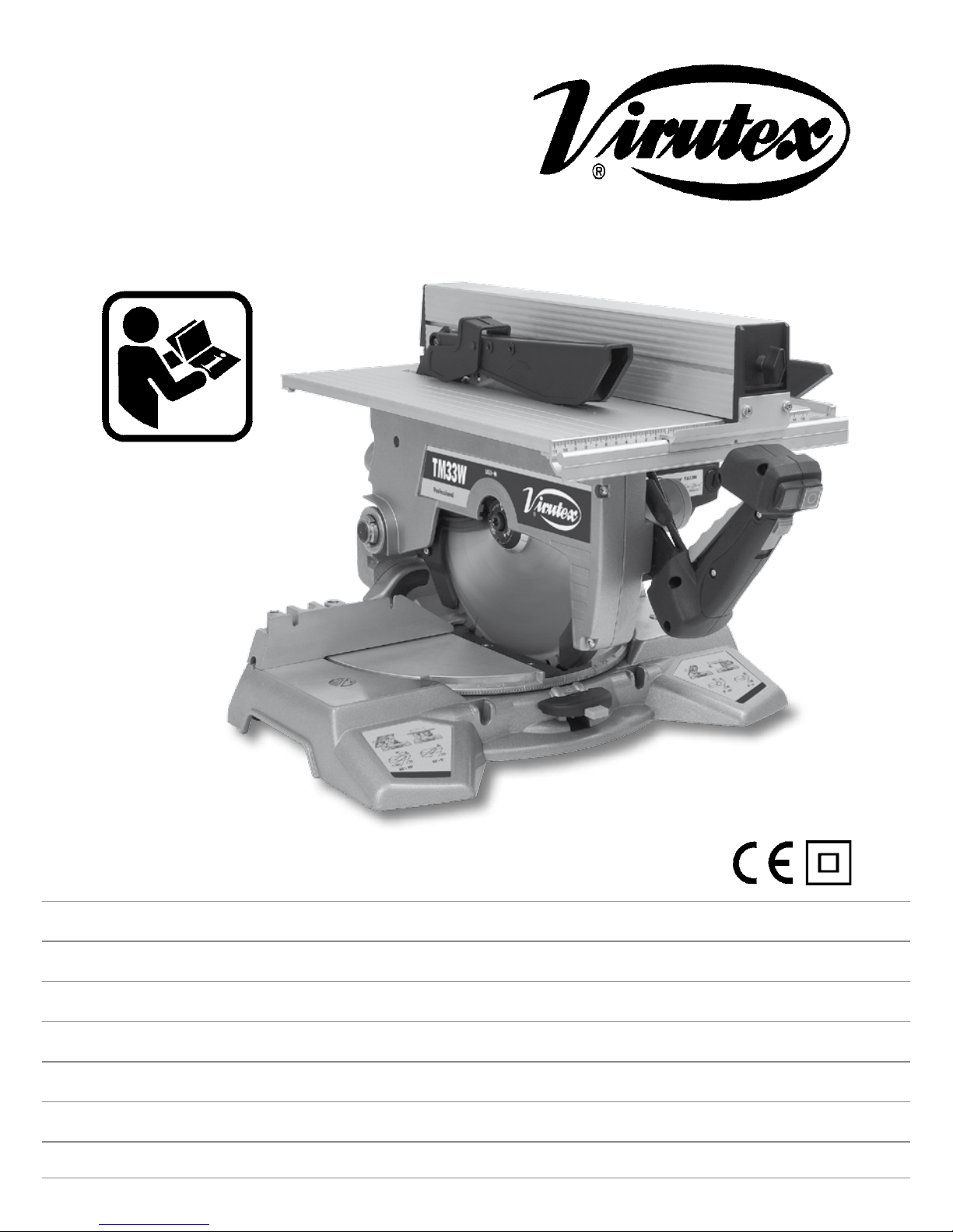
Tronzadora abatible
Tiltable mitre saw
Scie à onglet inclinable
Schwenkbare Gehrungssäge
Troncatrice inclinabile
Serra de esquadria inclinavel
Пила поворотная маятниковая
TM33W / TS33W
MANUAL DE INSTRUCCIONES
OPERATING INSTRUCTIONS
MODE D’ EMPLOI
GEBRAUCHSANWEISUNG
MANUALE D’ISTRUZIONI
MANUAL DE INSTRUÇÕES
ИНСТРУКЦИЯ ПО ЭКСПЛУАТАЦИИ
Page 2
2
E S P A Ñ O L
TRONZADORA ABATIBLE TM33WTS33W
Nota importante
Antes de utilizar la máquina lea atentamente el FOLLETO DE INSTRUCCIONES
GENERALES DE SEGURIDAD que se adjunta con la documentación de la misma.
Conservar adecuadamente el FOLLETO
indicado y el presente MANUAL DE
INSTRUCCIONES para posibles consultas
posteriores.
SÍMBOLOS
Los símbolos mostrados a continuación pueden ser de
importancia en el uso de la herramienta eléctrica. Es
importante que retenga en su memoria estos símbolos
y su significado. La interpretación correcta de estos
símbolos le ayudará a manejar mejor, y de forma más
segura, la herramienta eléctrica.
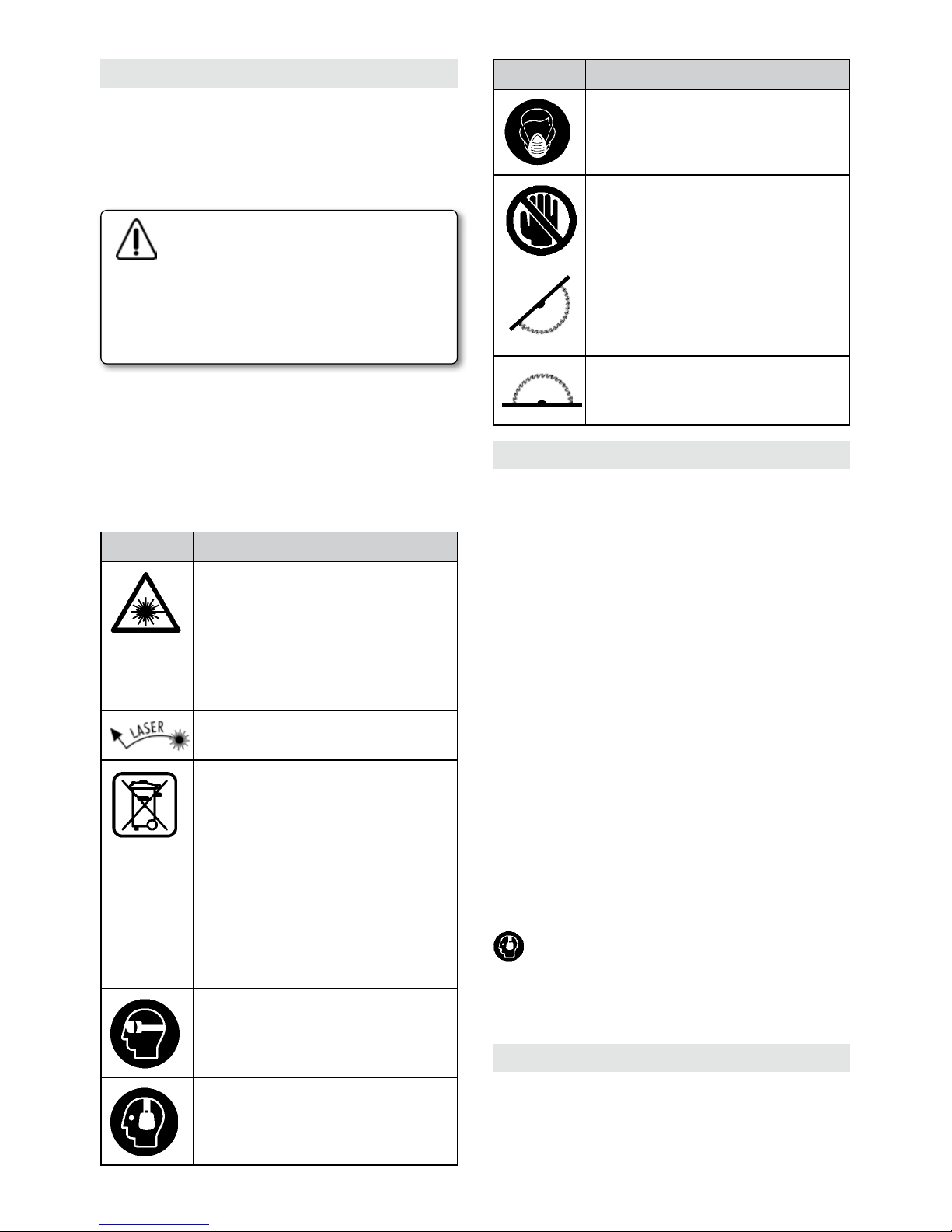
Simbología Significado
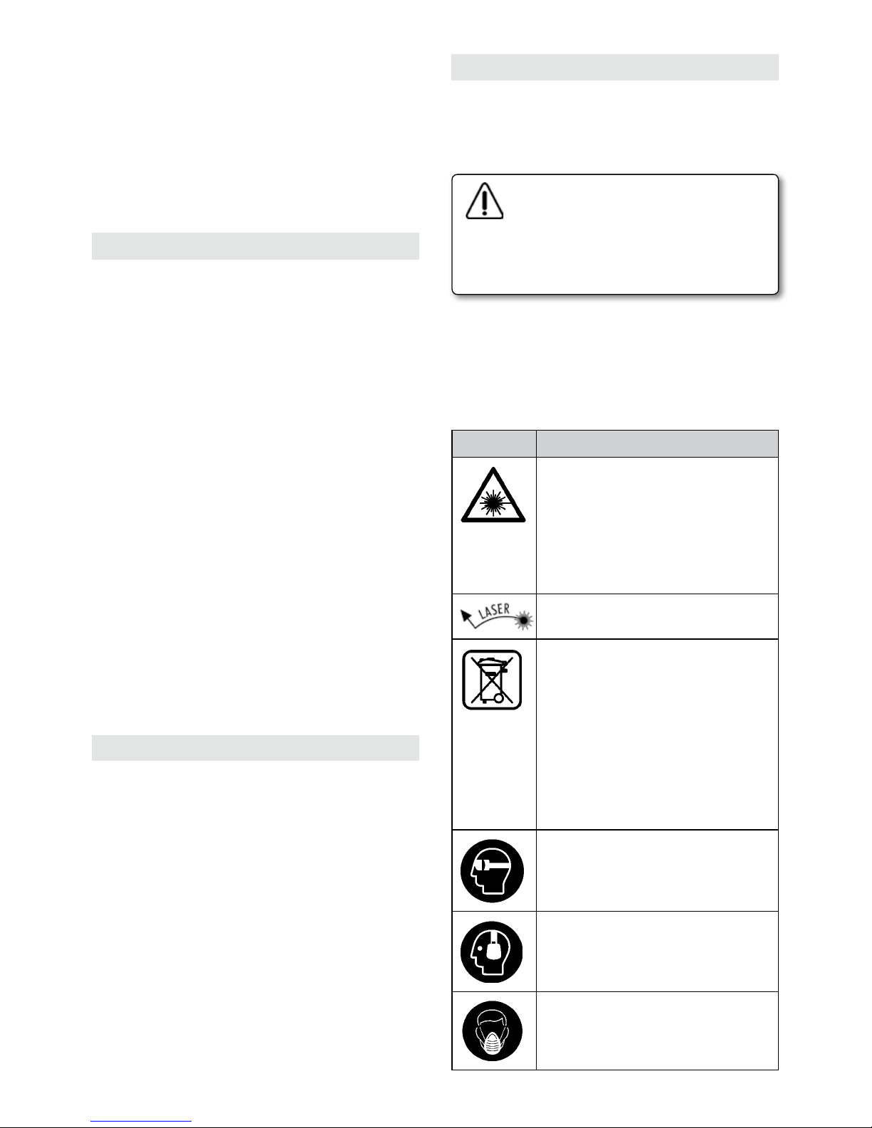
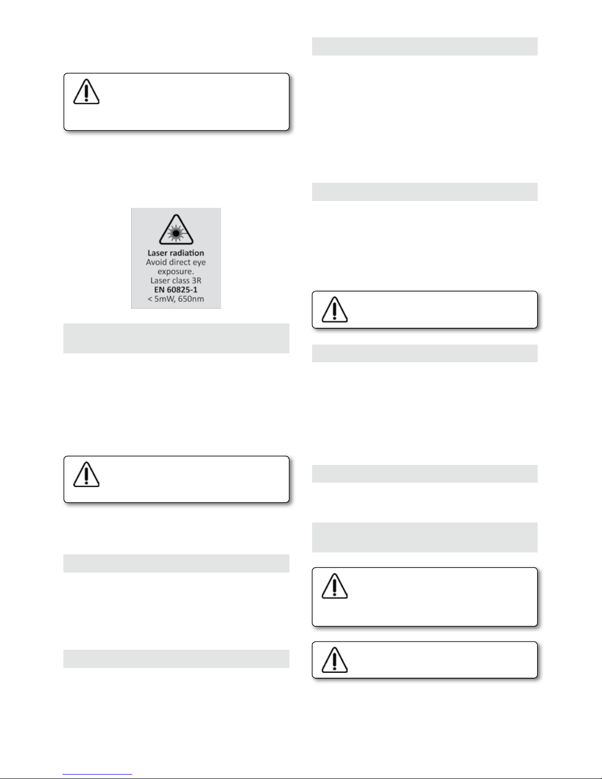
No oriente el rayo láser contra personas
ni animales, ni mire directamente hacia
el rayo láser. Esta herramienta eléctrica
genera radiación láser de la clase 3 según EN60825-1. Esta radiación puede
cegar a las personas.
Orificio de salida del láser
Sólo para los países de la UE: ¡No
arroje las herramientas eléctricas a
la basura! Conforme a la Directiva
Europea 2002/96/CE sobre aparatos
eléctricos y electrónicos inservibles,
tras su transposición en ley nacional,
deberán acumularse por separado las
herramientas eléctricas para ser sometidas a un reciclaje ecológico.
Utilice gafas de protección.
Utilice protectores auditivos. El ruido
intenso puede provocar sordera.
página/page
seite/pagina
страница
MANUAL DE INSTRUCCIONES
OPERATING INSTRUCTIONS
MODE D'EMPLOI
GEBRAUCHSANWEISUNG
MANUALE D'ISTRUZIONI
MANUAL DE INSTRUÇÕES
ИНСТРУКЦИЯ
ПО
ЭКСПЛУАТАЦИИ
ESPAÑOL Tronzadora abatible TM33W-TS33W
2
ENGLISH TM33W-TS33W Tiltable mitre saw
8
FRANÇAIS Scie à onglet inclinable TM33W-TS33W
14
DEUTSCH Schwenkbare Gehrungssäge TM33W-TS33W
20
ITALIANO Troncatrice inclinabile TM33W-TS33W
26
PORTUGUÉS Serra esquadria inclinavel TM33W-TS33W
32
РУССКИЙ Пила поворотная маятниковая TM33W-TS33W
38
Page 3
3
(*) Unicamente modelo TM33W
3. ELEMENTOS DE SEGURIDAD
3.1 INTERRUPTOR
La máquina dispone de un interruptor pulsador situado
en la empuñadura y un pulsador de enclavamiento para
el trabajo con mesa superior.
Para el trabajo de tronzado presionar sobre el botón de
puesta en marcha del interruptor a la vez que accionamos
la palanca B1 (Fig. 1) de modo que al cesar la presión
sobre esta la máquina se para automáticamente. Este
dispositivo de seguridad permite no tener que estar
presionando sobre el botón del interruptor mientras se
realiza la operación de tronzado y de este modo realizar
mas cómodamente dicha operación.
Para el trabajo de corte con mesa superior enclavar
el pulsador E1 (Fig. 8) y actuar sobre los botones de
paro marcha del interruptor. El pulsador se desclavará
automáticamente al llevar la máquina a su posición
de tronzado.
3.2 PROTECTORES MECÁNICOS
En la posición de reposo, la hoja de sierra queda totalmente recubierta por los protectores y la máquina
bloqueada en esta posición. La palanca B1 (Fig. 1) permite
el desbloqueo de la máquina previo al descenso.
Asegúrese de que la hoja de sierra queda
totalmente cubierta por los protectores
en la posición de reposo de la máquina.
Conserve siempre éstos en buen estado.
3.3 PROTECCIÓN CONTRA PUESTAS
EN MARCHA ACCIDENTALES POR
CORTES DEL SUMINISTRO ELÉCTRICO
La máquina está provista de un dispositivo que en caso
de caída de tensión o fallo del suministro eléctrico,
interrumpe el circuito e impide la puesta en marcha
accidental de la máquina cuando retorna la corriente,
aunque el botón de enclave del pulsador se mantenga
accionado.
Para la nueva puesta en marcha de la máquina presionar
sobre el botón de marcha del interruptor.
3.4 PROTECCIÓN CONTRA CORTOCIRCUITOS
El circuito de la máquina incorpora un fusible T1 (Fig.
8) que la protege contra cortocircuitos y sobrecargas.
El fusible se encuentra en la empuñadura de la máquina.
En caso de que fuese necesario sustituirlo por estar fuera
de servicio, proceda a desenroscar el tapón del portafusible y extraiga el fusible deteriorado. Sustituyalo por
otro del mismo calibre (5x20 10A Clase T).
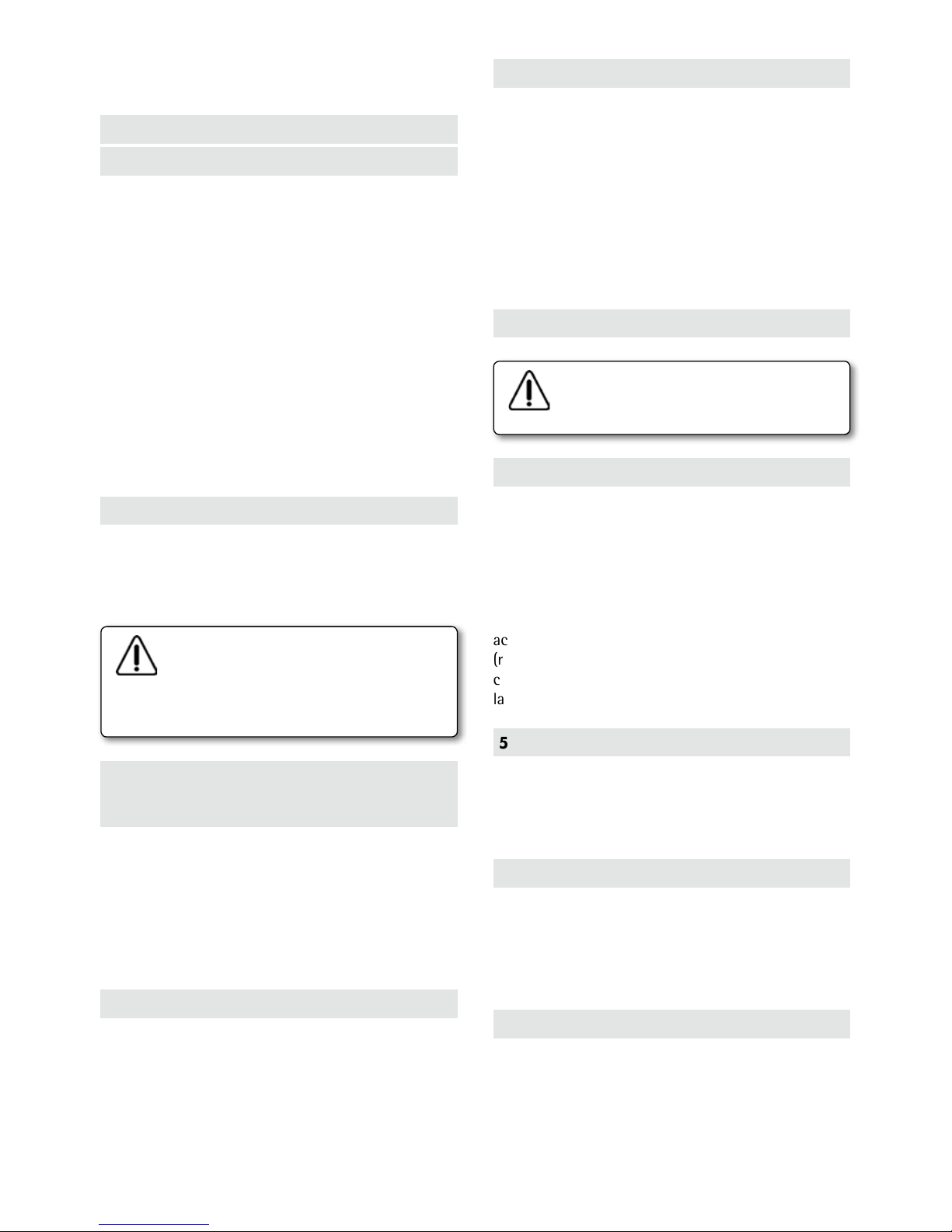
Simbología Significado
Utilice mascarilla antipolvo.
¡Área de peligro! Mantenga alejados
de este área las manos, dedos o brazos.
Símbolo para indicar el uso de la tronzadora como ingletadora.
Símbolo para indicar el uso de la tronzadora como sierra circular de mesa.
1. CARACTERÍSTICAS TÉCNICAS
Potencia absorbida.............................................1500 W
Motor...............................................................50/60 Hz
Revoluciones en vacío...............................3700/min
Tipo láser.......................................................................650 nm
<5 mW
Clase láser................................................................................3 R
Dimensiones disco de sierra:
diámetro exterior...................................................300 mm
diámetro interior........................................................30 mm
Plato giratorio:
Orientable a derecha e izquierda hasta 45° con enclave
fijo a: 0°- 15°- 22,5°- 30° y 45°.
Cabezal basculante:
Abatible desde 90° a 45° respecto a la base y en cualquier
posición de giro del plato desde 0° hasta 45° en sentido
izquierdo del mismo.
Peso...................................................................................20 Kg
Dimensiones embalaje................590x580x450 mm
Nivel de Presión acústica Ponderado A...................96 dBA
Nivel de Potencia acústica Ponderada A...............107 dBA
Incertidumbre de la medición.......................................K = 3 dBA
¡Usar protectores auditivos!
Nivel total de emisión de vibraciones...................ah: 3 m/s
2
Incertidumbre de la medición.....................................K: 1,5 m/s
2
2. CAPACIDADES MÁXIMAS DE CORTE
-Corte a 0° x 0° (Fig. 25)............................160x95 mm
(con suplemento de 36 mm)....................200x45 mm
-Corte a 0° x 45° (Fig. 26)...........................160x64 mm
-Corte a 45° x 0° (Fig. 27)...........................110x95 mm
-Corte a 45° x 45° (Fig. 28)...........................75x64 mm
-Corte sobre la mesa superior (*)...............máx. 55 mm
Page 4
4
4. DESEMBALAJE DE LA MÁQUINA
En el interior de la caja Ud. encontrará los elementos
siguientes:
-Tronzadora abatible según modelo (TM33W o TS33W)
-Llave allen e/c 8 mm.
-Conjunto tope regulación madera
-Empujador madera (solo TM33W)
-Manual de Instrucciones y hojas de despiece.
-Folleto de instrucciones generales de seguridad
-Documentación diversa
5. PREPARACIÓN Y PUESTA A PUNTO
Asegúrese que la máquina está desconectada de la red eléctrica antes de realizar
cualquier operación de preparación o
mantenimiento de la misma.
5.1 INSTALACIÓN
Una vez desembalada la máquina, fijar su empuñadura
al brazo basculante según el esquema de la etiqueta
sujeta a la misma.
Para el empleo de la máquina en puesto fijo, recomendamos su fijación sobre una mesa o banco de trabajo,
con una altura aproximada de 90 cm, mediante los
agujeros C previstos en la base (Fig. 2). Se recomienda
la utilización de nuestro accesorio MESA DE TRABAJO
TRANSPORTABLE MT58K (Ref. 5800100) (Fig. 29). La
máquina esta prevista exclusivamente para trabajos en
el interior por lo que no debe ser expuesta a la lluvia ni
a los ambientes húmedos.
5.2 EMPUÑADURA
Para situar la empuñadura de la máquina en posición
de trabajo, aflojar el pomo A (Fig. 8), bascular la empuñadura y volver a fijar el pomo A (la posición mas baja
está pensada para el corte con mesa superior).
5.3 DESBLOQUEO DEL CABEZAL
Presionar ligeramente sobre la empuñadura en el sentido
de tronzado y girar el eje fijación transporte B (Fig. 6) en
el sentido de las agujas del reloj hasta llevarlo a tope, a
continuación acompañar la máquina en sus movimiento
de elevación hasta su enclave en la posición de reposo.
5.4 COMPROBACIONES
Antes de conectar la máquina a la red, asegúrese del
buen estado de funcionamiento de los protectores y
mecanismos de seguridad.
Así mismo compruebe que la tensión y frecuencia de
la red corresponden con lo indicado en la placa de
características de la máquina.
En el caso de que se utilice un cable de prolongación,
verifique que la sección de los conductores del mismo
sea adecuada a la intensidad nominal de la máquina.
6. REGULACIONES
Asegúrese que la máquina está desconectada de la red eléctrica antes de realizar
cualquier manipulación.
La tronzadora sale ajustada de fábrica, no obstante
dispone de los mecanismos indicados a continuación
para ulteriores reajustes.
6.1 AJUSTE DEL CABEZAL ABATIBLE
Para ajustar la hoja de sierra a 90° respecto a la mesa
de la máquina, situar una escuadra de comprobación
entre ambas y seguir el siguiente proceso:
Aflojar la maneta D (Fig. 2) y corregir por el tornillo
E la posible desviación. Igualmente puede ajustarse el
cabezal abatido a 45° respecto a la base, actuando en
este caso sobre el tornillo F (Fig. 2).
6.2 AJUSTE DEL PLATO GIRATORIO
La máquina dispone de un enclave automático a 0°, 15°,
22.5°, 30° y 45° por lo que raramente deberá reajustarse en estas posiciones. En caso necesario enclavar la
máquina a 0°, y aflojando los tornillos G que sujetan
el regle H, desplazar éste hasta situarlo perfectamente
perpendicular a la sierra (Fig. 10).
6.3 AJUSTE DE LA PROFUNDIDAD
DE CORTE MÁXIMA
El tope de profundidad de corte viene dado por el tornillo
regulable I (Fig. 2). Éste deberá reajustarse cada vez que
se cambie el disco de sierra o se proceda a su afilado.
- Comprobar que la sierra no toque en
el fondo del plato una vez ajustado el
tope de bajada.
- Cambiar la tapeta del plato cuando esté
deteriorada o rota.
6.4 AJUSTE DE LA QUILLA
Para realizar el ajuste de la quilla se procederá de la
siguiente forma:
-Quitar la tapa V por medio de los tornillos W (Fig. 9).
-Aflojar los tornillos X (Fig. 7), ajustar la quilla y volver a
apretar los tornillos que la fijan, a continuación montar
de nuevo la tapa V.
Page 5
5
-La distancia entre los dientes de la hoja
de sierra y la quilla nunca deberá superar
los 5 mm.
- Utilice solamente hojas de sierra cuyo
cuerpo sea más delgado que el espesor
de la quilla y que a la vez la anchura de
los dientes sea superior a dicho espesor.
6.5 AJUSTE DEL TOPE DE SUBIDA
Para ajustar el tope de subida actuaremos sobre el tornillo
Y (Fig. 2), teniendo en cuenta que la máquina enclave
en la posición de reposo.
6.6 GUÍA LASER
La máquina va provista de una guía láser solidaria al disco
de sierra la cual proyecta un haz de luz sobre el material
a cortar que indica con gran precisión la línea sobre la
cual incidirá el disco de sierra. Haga coincidir el haz de
luz con el trazo que haya realizado previamente al corte.
La guía láser esta provista de un interruptor de inercia,
por lo cual solo se activa al girar el disco de sierra.
La guía láser incorpora también un
interruptor On/off T1 (Fig. 22) para
activar o desactivar su funcionamiento.
Es imprescindible poner el interruptor en
la posición Off para el corte con mesa
superior.
La herramienta eléctrica se suministra de serie con una
señal de advertencia en español R (Fig. 18).
Antes de la primera puesta en marcha, pegue encima
de la señal de aviso la etiqueta adjunta redactada en
su idioma.
7. APLICACIONES DE TRONZADO.
CONDICIONES DE USO PREVISTAS
Esta máquina permite el tronzado con eficacia y precisión
de piezas de madera, plástico y perfiles de aluminio.
El regle de la máquina va provisto de unas ranuras que
permiten la rápida colocación de un apoyo de madera
R2 para evitar el astillado del material a cortar (Fig.
18). Siendo muy recomendable su utilización al cortar
materiales frágiles o de poco grosor.
Es imprescindible el uso de prensores
(ver apartado 10) para el tronzado de
perfiles de aluminio, plástico y piezas
largas (Fig. 20).
No iniciar el corte hasta que la hoja no haya alcanzado
la plena velocidad de giro.
7.1 CORTE A 0° x 0°
Proceder como indica la (Fig. 18), realizando el corte
con la ayuda de la guía láser. El tope de apoyo de la
madera va provisto de una regla milimetrada S1 (Fig.
19) para facilitar la operación de corte. La regla marca
la longitud del sobrante que se corta.
7.2 CORTE A 0° x 45°
Aflojar la maneta D (Fig. 2) y abatir el cabezal hasta el
tope de 45° o a cualquier otro ángulo intermedio que
se desee, con ayuda del indicador de ángulo Z1 (Fig. 15),
apretar de nuevo la maneta D en la posición seleccionada
7.3 CORTE A 45° x 0°
Presionar sobre la palanca E2 (Fig. 5) y girar el plato
hacia la izquierda o la derecha hasta que el índice
señale los 45° o cualquiera de las posiciones fijas (15°,
22°30', 30°, 45°).
Si se desea realizar un corte el cual no coincida con
ninguna de las posiciones fijas del plato pulsar sobre la
palanca E2 (Fig. 3) y seguidamente presionar hacia dentro
el gatillo E3 (Fig. 3) esto permite desbloquear el plato
consiguiendo de esta manera regular el ángulo exacto
que se precise, posteriormente fijar el plato mediante
el pomo K (Fig. 3)
7.4 CORTE A 45° x 45°
Presionar sobre la palanca E2 (Fig. 4) y girar el plato hacia
la izquierda hasta su enclave automático a 45°. Aflojar
la maneta D y abatir el cabezal hasta el tope de 45° o
ángulo intermedio deseado, y fijarlo de nuevo (Fig. 4).
La máquina permite asimismo el abatimiento del cabezal en cualquier posición del plato (solo en el giro a
izquierdas del mismo).
Asegúrese que el brazo basculante quede perfectamente fijado en su posición
cuando se hagan cortes a inglete.
7.5 CORTE ESPECIAL 200 x 45 mm
Ésta máquina permite cortar en la posición de 0°x0° hasta
un máximo de 200x45 mm. Para ello sólo se tendrá que
Page 6
6
aflojando los pomos M (Fig. 1) y situando la mesa a la
altura de corte deseada mediante el pomo de ajuste de
altura M2, procurando que la hoja salga del material a
cortar solo la altura del diente, apretar firmemente los
pomos a la altura seleccionada.
Enclavar el pulsador E1 en posición para corte con mesa
superior (Fig. 8).
Terminado el trabajo de corte sobre la mesa colocar de
nuevo el perfil de aluminio en su posición protectora
antes de usar la máquina en su función de tronzado.
No utilizar la mesa superior sin colocar
el carenado de aspiración.
No trabaje nunca sin el protector superior.
Usar el bastón de empuje E5 que se suministra con la máquina para alimentar
la pieza cuando pase por la hoja de sierra
(Fig. 21). En uno de los laterales de la
mesa superior, la máquina dispone de
dos soportes de anclaje previstos para
colocar el bastón de empuje E5 durante
su transporte.
Usar correctamente la protección superior
de la hoja.
Asegúrese que el brazo basculante queda perfectamente fijado en su posición
cuando trabaje con la mesa superior.
9. SALIDA ASPIRACIÓN
Ésta máquina va provista en su parte posterior de una
salida de aspiración de 38 mm de diámetro, mediante
la cual es posible la conexión a un tubo flexible que
puede a su vez ser adaptado a un aspirador industrial o
a cualquier sistema de aspiración centralizado para la
recogida de viruta y polvo. Se recomienda la conexión
a nuestros aspiradores AS182K, AS282K.
Para el trabajo sobre la mesa superior, además de realizar la conexión anterior, el carenado va provisto de la
boquilla D2 (Fig. 6) sobre la cual es necesario conectar
el acoplamiento de aspiración standard (ref. 6446073
3,5 m / ref. 1746245 5 m) para una perfecta evacuación
de la viruta.
Es aconsejable conectar siempre la máquina a un dispositivo de recogida de polvo y viruta.
10. ACCESORIOS OPCIONALES
Ref. 3345416 Juego 2 prensores (Fig. 20). Su uso es imprescindible para el tronzado de perfiles de aluminio y plásticos.
Ref. 3345470 Juego asas laterales (Fig. 19)
Ref. 7246098 Escuadra mesa superior
Ref. 5800100 Mesa de trabajo transportable MT58K (Fig. 29)
Ref. 8200100 Aspirador industrial AS182K
Ref. 8200200 Aspirador industrial AS282K
colocar sobre la mesa inferior los suplementos N2 ref.
3346388 Juego suplementos para corte 200 mm (accesorio
opcional) y proceder normalmente al tronzado. Esto es
posible gracias al protector sierra retráctil R (Fig. 16) que
va retirándose a medida que se va avanzando en el corte.
7.6 CORTE DE PIEZAS EN SERIE
Para el corte de piezas en serie se montará el tope de
longitudes A1, regulándolo y bloqueándolo a la medida
deseada (Fig. 5).
8. CORTE SOBRE MESA SUPERIOR.
CONDICIONES DE USO PREVISTAS
(solo para modelo TM33W)
La guía láser incorpora también un
interruptor On/off T1 (Fig. 22) para
activar o desactivar su funcionamiento.
Es imprescindible poner el interruptor en
la posición Off para el corte con mesa
superior.
Sobre la mesa superior sólo puede cortarse
madera o plástico, no utilizarla nunca
para cortar aluminio o perfiles.
Para utilizar la máquina en esta modalidad de corte,
primero se debe proceder a colocar sobre la máquina
el carenado Inferior K1 (Fig. 6) que impide cualquier
contacto accidental con el disco de sierra por debajo
de la mesa. Para ello encajar primero la parte derecha
del carenado sobre la máquina y a continuación la
parte izquierda. Una vez estén encajadas ambas partes
proceder a unirlas mediante las grapas de cierre D1 (Fig.
6). A continuación bloquear la máquina en posición de
transporte por medio del eje B (Fig. 6), comprobando
que el carenado quede perfectamente encajado e
inmovilizado.
Seguidamente aflojar el pomo A y bajar la empuñadura
hasta su posición inferior (Fig. 8). Aflojar el pomo L,
retirar el perfil de aluminio superior que encierra el
protector de la hoja y utilizarlo como guía lateral de
corte bloqueándolo a la distancia de la hoja deseada (Fig.
11), este protector dispone en su lateral de una ranura
que incorpora dos tuercas E4 (Fig. 11) previstas para fijar
un listón de madera que llegue hasta el eje vertical del
centro de la hoja de la sierra. La colocación de este listón
(Fig. 17) es conveniente para realizar cortes de pequeña
longitud (tarugos y zoquetes) ya que en este tipo de
cortes la pieza cortada al salir del centro de la hoja si no
encuentra una cierta holgura en su salida queda retenida
por el sentido de giro de la hoja puediendo provocar
una expulsión incontrolada de la pieza.
La salida de la hoja respecto a la mesa se regulará
Page 7
7
11. MANTENIMIENTO Y LIMPIEZA
Asegúrese que la máquina esté desconectada de la red eléctrica antes de realizar
cualquier manipulación.
11.1 CAMBIO DE LA HOJA DE SIERRA
Aflojar los pomos M (Fig. 1) y levantar la mesa a su
posición máxima. Seguidamente, presionar el botón O
y girar la sierra lentamente hasta que ésta se enclave
(Fig.1). A continuación aflojar el tornillo P (Fig. 12),
mediante la llave de servicio que se suministra, en el
sentido de las agujas del reloj. Una vez suelta la hoja
de sierra, desplazarla hacia arriba para después poder
extraerla hacia abajo, por el lateral del cabezal de la
máquina, salvando la protección.
Seguir el proceso inverso para montar la nueva hoja
de sierra, orientando la flecha de ésta con la misma
dirección de la existente en la protección basculante
y comprobando la perfecta limpieza de los asientos de
los elementos y asegurándose que el platillo laser de
sujección exterior encaja perfectamente en los rebajes
del extremo del eje.
Una vez efectuado el montaje del disco, mover este
ligeramente hasta que el botón de blocaje quede liberado.
- Asegúrese que nueva hoja de sierra que
se monte tenga el mismo diámetro que
la sustituida.
- No usar hojas de sierra que estén dañadas o deformadas.
- Seleccionar las hojas de sierra en relación al material que se vaya a cortar.
- Usar sólo las hojas de sierra que cumplan las condiciones expresadas en este
manual y en cualquier caso asegúrese de
que la hoja tenga el cuerpo más delgado
que el espesor de la quilla y que a la vez
la anchura de los dientes sea superior al
espesor de ésta.
11.2 CAMBIO DE LAS CORREAS
Para cambiar las correas de la máquina se procederá
del modo siguiente:
-Aflojar los tornillos S (Fig. 13) y quitar la tapa transmisión.
-Quitar las correas rotas o desgastadas y sustituirlas por
otras nuevas, teniendo en cuenta que siempre deberá
montarse en primer lugar la correa interior, con lo cual
el tren de poleas trasero quedará montado en el brazo
basculante de la máquina (Fig. 13). A continuación se
montará la correa exterior, para lo cual deberá tenerse
en cuenta que ésta engrane perfectamente en las poleas,
y ayudándose de la llave de servicio que se utiliza para
el cambio de sierra, se hará girar lentamente el eje al
mismo tiempo que se empuja la tapa de transmisión
hacia el brazo basculante. Es importante asegurar que los
pivotes de centraje T entren suavemente en sus encajes.
NOTA: El ensamblaje de la tapa de transmisión con el
brazo basculante se tendrá que realizar de una forma
manual y sin golpear o forzar en ningún caso ninguna
de las piezas, ya que en tal caso no se aseguraría su
perfecto funcionamiento.
11.3 CAMBIO DE ESCOBILLAS
Las escobillas deben ser sustituidas cuando tengan una
longitud mínima de 5 mm. Para ello, quitar los tapones U
(Fig. 14) que las protegen y sustituirlas por otra originales
VIRUTEX, asegurándose de que deslicen suavemente en
el interior de las guías.
Es aconsejable dejar la máquina en marcha en vacío
durante algunos minutos después de un cambio de
escobillas.
Aproveche el cambio de escobillas para verificar el
estado del colector. Si éste presentase quemaduras o
resaltes es aconsejable llevarlo a reparar a un servicio
técnico VIRUTEX.
11.4 FRENO MOTOR
La máquina va provista de un freno mecánico centrífugo
que posibilita que el tiempo transcurrido desde que se
desactiva el pulsador del Interruptor hasta la completa
inmovilización de la hoja de sierra sea inferior a diez
segundos.
Para su seguridad, y debido a la complejidad de la
operación, recomendamos que cuando por desgaste de
las pastillas observe que el tiempo de parada de la hoja
supera ese margen de tiempo, se dirija a un Servicio
Oficial de Asistencia Técnica VIRUTEX para proceder a
su sustitución.
11.5 SUSTITUCIÓN DE LAS PILAS
DE LA GUÍA LASER
Una vez agotadas las pilas de la guía láser sustituirlas
por unas nuevas del siguiente modo:
Aflojar los tornillos R1 (Fig. 23) retirar la cubierta portapilas y extraer las pilas agotadas de su alojamiento
sustituyéndolas por unas nuevas. Proceder en sentido
inverso para su montaje teniendo en cuenta que el polo
positivo de las pilas debe quedar hacia la cara exterior
del portapilas (Fig. 24)
Utilizar exclusivamente pilas del tipo LR44.
No utilizar pilas recargables.
11.6 LUBRICACIÓN Y LIMPIEZA
Page 8
8
La máquina se entrega totalmente lubricada de fábrica no
precisando cuidados especiales a lo largo de su vida útil,
siendo suficiente con limpiar y engrasar periódicamente
con aceite las articulaciones mecánicas.
Es importante limpiar siempre cuidadosamente la
máquina después de su utilización mediante un chorro
de aire seco.
Mantener el cable de alimentación en perfectas condiciones de uso.
12. NIVEL DE RUIDO Y VIBRACIONES
Los niveles de ruido y vibraciones de esta herramienta
eléctrica han sido medidos de acuerdo con la Norma
Europea EN 61029-1 y EN 61029-2-11 (TM33W) y EN
61029-2-9 (TS33W) y sirven como base de comparación
con máquinas de semejante aplicación.
El nivel de vibraciones indicado ha sido determinado
para las aplicaciones principales de la herramienta,
y puede ser utilizado como valor de partida para la
evaluación de la exposición al riesgo de las vibraciones.
Sin embargo, el nivel de vibraciones puede llegar a ser
muy diferente al valor declarado en otras condiciones
de aplicación, con otros útiles de trabajo o con un
mantenimiento insuficiente de la herramienta eléctrica
y sus útiles, pudiendo llegar a resultar un valor mucho
más elevado debido a su ciclo de trabajo y modo de uso
de la herramienta eléctrica.
Por tanto, es necesario fijar medidas de seguridad de
protección al usuario contra el efecto de las vibraciones,
como pueden ser mantener la herramienta y útiles de
trabajo en perfecto estado y la organización de los
tiempos de los ciclos de trabajo (tales como tiempos
de marcha con la herramienta bajo carga, y tiempos de
marcha de la herramienta en vacío y sin ser utilizada
realmente ya que la reducción de estos últimos puede
disminuir de forma sustancial el valor total de exposición)
13. GARANTÍA
Todas las máquinas VIRUTEX tienen una garantía válida
de 12 meses a partir del día de suministro, quedando
excluidas todas las manipulaciones o daños ocasionados
por manejos inadecuados o por desgaste natural de la
máquina. Para cualquier reparación dirigirse al Servicio
Oficial de Asistencia Técnica VIRUTEX.
En la inquietud continua por la mejora y actualización
de sus productos, VIRUTEX se reserva el derecho de
modificarlos sin previo aviso.
E N G L I S H
TILTABLE MITRE SAW TM33W-TS33W
Important note
Before using the machine carefully read
the GENERAL SAFETY INSTRUCTIONS
LEAFLET, which is included in the machine
documentation. Keep the leaflet safely
along with this INSTRUCTION MANUAL
for possible future consultations.
SYMBOLS
The following symbols can be important for the operation
of your power tool. Please memorise the symbols and
their meanings. The correct interpretation of the symbols
helps you operate the power tool better and more secure.
Symbol Meaning
Do not direct the laser beam at persons
or animals and do not stare into the
laser beam yourself, not even from
a distance. This power tool produces
class 3 laser radiation according to
EN60825-1. This radiation can lead to
persons being blinded.
Laser output hole
Only for European Union countries:
Do not dispose of power tools into
household waste! According the European directive 2002/96/EC for waste
electrical and electronic equipment
and its implementation into national
laws, power tools that are no longer
usable must be collected separately
and disposed of in an environmentally
correct manner.
Wear safety goggles.
Wear ear protectors. Exposure to noise
can cause hearing loss.
Wear a dust protection mask.
Page 9
9
Symbol Meaning
Danger area! Keep hands, fingers or
arms away from this area.
Symbol for use of the mitre saw as a
chop and mitre saw.
Symbol for use of the mitre saw as a
table saw.
1. TECHNICAL CHARACTERISTICS
Input power...................................................1500 W
Motor.........................................................50/60 Hz
No-load speed..........................................3700/min
Type of laser.......................................................................650 nm
<5 mW
Laser class................................................................................3 R
Dimensions of saw disc:
External diameter.........................................300 mm
Internal diameter............................................30 mm
Revolving table:
Adjustable, right and left to 45° with fixed stops at 0°,
15°, 22,5°, 30° and 45°.
Tilting head:
Can tilt from 90 to 45° at any position of the revolving
table from 0° to 45° to the left of the same.
Weight.............................................................20 kg
Packing dimensions.....................590x580x450 mm
Weighted equivalent continuous
acoustic pressure level A...................................................96 dBA
Acoustic power level A....................................................107 dBA
Uncertainty...................................................................K = 3 dbA
Wear ear protection!
Vibration total values.................................................ah: 3 m/s
2
Uncertainty....................................................................K: 1.5 m/s
2
2. MAXIMUM CUTTING CAPACITY
-Cut at 0°x 0° (Fig. 25).......................160x95 mm
(with 36 mm supplement).........................200x45 mm
-Cut at 0°x45° (Fig. 26).............................160x64 mm
-Cut at 45°x0° (Fig. 27)............................110x95 mm
-Cut at 45°x45° (Fig. 28)...........................75x64 mm
-Cut on upper table (*)...............................max 55 mm
(*) Only for model TM33W
3. SAFETY ELEMENTS
3.1 ON/OFF BUTTON
The machine has a push-button switch located on the
handle and a locking button for work with a raised table.
For parting purposes, press the switch button while
activating lever B1 (Fig. 1) so that when pressure is
stopped, the machine comes to an automatic halt.
This safety device eliminates the need for pressing the
switch button continually while the parting process is
in progress, thus facilitating your work.
For cutting with the raised table, lock button E1 (Fig.
8) and press the stop-start buttons on the switch. The
button will unlock automatically when the machine is
set as a parting tool.
3.2 MECHANICAL PROTECTION
When the saw blade is not in use it is totally covered by
the protectors and the machine is locked in this position.
Lever B1 (Fig. 1) releases the machine before it is lowered.
Ensure that the saw blade is totally
covered by the protectors when not in
use. Always keep the protectors in good
condition.
3.3 PROTECTION AGAINST ACCIDENTAL STARTING RESULTING FROM CUT OFF OF ELECTRICITY
This interrupts the circuit and prevents the machine from
being accidentally switched on when power is restored,
even though the locking switch may still be on.
To restart the machine, press the start switch.
3.4 PROTECTION AGAINST SHORT CIRCUITS
The machine's circuit includes a T1 fuse (Fig. 8) which
protects it from short-circuiting and overloading.
The fuse is located on the machine handle. Should it
have to be replaced, unscrew the lid of the fuse box and
remove the burnt-out fuse. Replace it with another one
of the same type (5x20 10A, type T).
4. UNPACKING THE MACHINE
Contained in the case you will find the following
elements:
- Tiltable mitre saw according to model (TM33W-TS33W)
- 8 mm size Allen key
- Wood regulation stop equipment
- Pusher (only TM33W)
- Instruction manual and parts sheets
- General safety instruction leaflet
- Other documentation
5. PREPARING YOUR MACHINE
Page 10
10
Ensure that the machine is disconnected
from the mains before carrying out any
preparation or maintenance work on
the machine.
5.1 INSTALLATION
Once you have unpacked the machine, fasten its handle
to the swinging arm as shown in the diagram on the
attached label.
When using the machine in a fixed location we recommend that it be secured to a table or workbench
at a height of approximately 90 cm using the holes
C located in the base (Fig. 2). To facilitate your work,
we recommend using our MOVABLE WORKING TABLE
MT58K (ref 5800100) (Fig. 29). The machine is designed
exclusively for interior working and as such should not
be exposed to rain or humid environments.
5.2 HANDLE
Place the handle of the machine in working position by
releasing the knob A (Fig. 8). Rotate the handle to the
top position and tighten knob A.
5.3 UNLOCKING THE HEAD
Lightly press the handle in the direction of the cut and
turn the transport locking catch B (Fig. 6) clockwise until
it reaches the stop, then follow the machine as it moves
up to until it is locked in resting position.
5.4 CHECKS
Before connecting to the mains ensure that the protectors
and safety mechanisms on the machine are working
correctly and check that the voltage corresponds to
that shown on the characteristics plate.
If an extension cable is being used check that the cross
section of the wires are suitable for the nominal current
of the machine.
6. ADJUSTING THE MACHINE
Ensure that the machine is disconnected
from the mains before carrying out any
adjustments.
The mitre saw leaves the factory adjusted; however
further adjustments can be made with the mechanisms
described below.
6.1 ADJUSTING THE TILTING HEAD
To adjust the saw blade to 90° with respect to the
machine table, place a square between the two and
proceed as follows:
Release the handle D (Fig. 2) and correct any deviation
using screw E. The head can also be adjusted to 45° with
respect to the table by turning screw F (Fig. 2).
6.2 ADJUSTING THE REVOLVING PLATE
The machine is equipped with an automatic lock at 0°,
15°, 22.5°, 30° and 45° so that these positions should
only rarely need adjustment. If this is necessary, lock
the machine at 0° and release screws G which hold in
place rule H; move the rule until it is perpendicular to
the saw (Fig. 10).
6.3 ADJUSTING THE MAXIMUM CUTTING DEPTH
The maximum cutting depth is determined by the adjusting screw I (Fig. 2). This should be readjusted every
time the saw blade is changed or sharpened.
- Check that the saw is not touching the
bottom of the plate once the maximum
depth has been adjusted.
- Change the cover on the plate when it
is worn or broken.
6.4 ADJUSTING THE KEEL
To adjust the keel proceed as follows:
- Remove cover V using screws W (Fig. 9).
- Release screws X (Fig. 7), adjust the keel and tighten
up the screws which secure it; then replace the cover V.
- The distance between the teeth of the
saw blade and the keel must never be
greater than 5 mm.
- Use only saw blades whose body is
thinner than the thickness of the keel
and at the same time whose teeth are
wider than this thickness.
6.5 ADJUSTING THE MAXIMUM
RAISED POSITION
To adjust the maximum raised position turn screw
Y (Fig. 2) remembering that the machine locks into
resting position.
6.6 LASER GUIDE
The machine is fitted with a laser guide that works in
conjunction with the saw blade, projecting a light beam
onto the material to be cut, indicating the line for the
saw blade with great precision. Match the light beam
up with the line previously drawn for cutting.
Page 11
11
The laser guide has an inertia switch, so it is only activated
when the saw blade is turning.
The laser guide also includes an On/
off switch T1 (Fig. 22) to activate or
deactivate it. The switch must be turned
to ‘Off’ for cutting on the upper table.
The electric tool is supplied as standard with a warning
sign in Spanish R (Fig. 18).
Before starting for the first time, stick the attached
label written in your language over the warning sign.
7. APPLICATIONS OF MITERING, INTENDED
CONDITIONS OF USE
This machine enables you to cut pieces of wood, plastic
and aluminium angles efficiently and precisely.
The rule on the machine is grooved which allows you
to quickly position a wood R2 support to prevent any
splintering of the material being cut (Fig. 18). Use of
the knobs is strongly recommended when cutting fragile
or thin materials.
It is essential to use clamps (see section
10) for cutting aluminium angles, plastic
or long pieces (Fig. 20).
Do not start any cut until the blade has reached its full
speed of rotation.
7.1 CUTTING AT 0° x 0°
Continue as shown in (Fig. 18), making the cut with the
assistance of the laser guide. The wood support stop is
fitted with a millimeter ruler S1 (Fig. 19) to facilitate
the cutting operation. The ruler marks the excess length
to be cut.
7.2 CUTTING AT 0° x 45°
Release handle D (Fig. 2), lower the head to the 45° stop
or any other intermediate angle as required, using the
angle indicator Z1 (Fig. 15); and tighten handle D in
the selected position.
7.3 CUTTING AT 45° x 0°
Press down lever E2 (Fig. 5) and turn the plate towards
the left or right until the index marks 45º or any of the
standard positions (15º, 22º30', 30º, 45º).
Should you wish to make a cut that does not match
any of the plate's standard positions, push down lever
E2 (Fig. 3) and then push it towards trigger E3 (Fig. 3).
This will unlock the plate, enabling you to regulate
the exact angle you require. Then lock the plate using
knobs K (Fig. 3).
7.4 CUTTING AT 45° x 45°
Press down lever E2 (Fig. 4) and turn the plate towards
the left until it locks into place at 45º. Loosen handle D
and lower the head to the stop at 45º or the intermediate
angle you wish. Lock it in place once again (Fig. 4).
The machine also enables you to tilt the head to any
position on the plate (only by turning it to the left).
Ensure that the moving arm is well secured
in position when mitering.
7.5 SPECIAL CUTS 200 x 45 mm
In the 0°x0° position this machine can make cuts up to
200 x 45 mm. For these cuts must be placed on the lower
table to do this, just fit supplements N2 ref. 3346388
supplements for 200 mm cuts (optional accessory) to the
bottom table and then the cut can be made as normal.
This is possible due to the retractable saw protector R
(Fig. 16) which retracts as the cut is made.
7.6 MULTIPLE CUTS
To make multiple cuts the length stop A1 must be installed and regulated to the required measurement (Fig. 5)
8. CUTS ON THE UPPER TABLE,
INTENDED CONDITIONS OF USE
(only with models TM33W)
The laser guide also includes an On/
Off switch T1 (Fig. 22) to activate or
deactivate it. The switch must be turned
to ‘Off’ for cutting on the upper table.
On the upper table only plastics and wood
can be cut, never aluminium or angles.
To use the machine in this cutting mode the lower cover
K1 (Fig. 6) should be positioned on the machine which
prevents any accidental contact of the saw disc under
the table. Fit the right-hand side of the fairing onto
Page 12
12
the machine first, followed by the left-hand side. Once
both parts are fitted on, proceed to join them using
closure clamps D1 (Fig. 6). Then lock the machine in its
transporting position using catch B (Fig. 6), checking that
the cover is perfectly in place and fixed. Release knob A
and lower the handle (Fig. 8). Release knob L, withdraw
the upper aluminium angle which covers the blade
protector and use it as a lateral cutting guide, locking
it again at the required distance from the saw (Fig. 11),
this protector has a side slot that includes two nuts E4
(Fig. 11) designed to lock the wooden fillet that extends
up to the vertical axis of the centre of the saw blade.
Placing this wooden fillet (Fig. 17) is necessary when
making short cuts (dowels or stocks). This is because in
this type of cutting, when the cut piece is ejected from
the centre of the leaf, if it lacks space in coming out, the
turning of the blade, which could cause the accidental
expulsion of the part, will retain it.
The exit position of the saw with respect to the table is
regulated by releasing knobs M (Fig. 1) and placing the
table at the required cutting height, using the height
adjustment knob M2, ensuring that the blade overhangs
the material to be cut only at the level of the tooth,
tighten up the knobs at the selected height.
Lock button E1 in place for cutting with a raised table
(Fig. 8).
Once the cutting work on the table is finished replace
the aluminium angle in the protection position before
using the machine as a mitre saw again.
Do not use the upper table without putting
the lower protecting cover in position.
Never work without the upper protector.
Use push stick E5 supplied with this
machine to feed in the part to the saw
blade (Fig. 21). The machine is equipped
on one of the sides of the upper table
with two fastening supports with which to
attach the E5 thrust rod during transport.
Use the upper protector of the upper
blade correctly.
Ensure that the tilting arm is well secured in position when working on the
upper table.
9. DUST COLLECTION OUTLET
On the rear of this machine there is a Ø 38 mm dust
collection outlet, where it is possible to connect up a
flexible tube, adapting an industrial aspirator or any
system of centralised aspiration for collecting dust and
shavings. We recommend connection to our aspirators
AS182K, AS282K.
For work on the upper table, and in addition to the
connection mentioned above, the fairing is provided with
a nozzle D2 (Fig. 6) to which the standard dust collector
attachment (Ref. 6446073 3.5 m / Ref. 1746245 5 m)
must be connected for perfect collection of the shavings.
We recommend you keep the machine permanently
connected to a dust and shavings collection system.
10. OPTIONAL ACCESSORIES
Ref. 3345416 Set of two pressers (Fig. 20). It is indispensable for cutting aluminium and plastic profiles.
Ref. 3345470 Set of side handles (Fig. 19)
Ref. 7246098 Square for upper table
Ref. 5800100 Movable working table MT58K (Fig. 29)
Ref. 8200100 Aspirator AS182K
Ref. 8200200 Aspirator AS282K
11. MAINTENANCE AND CLEANING
Ensure that the machine is disconnected
from the mains before carrying out any
of these operations.
11.1 CHANGING THE SAW BLADE
Release knobs M (Fig. 1) and raise the table to its maximum position. Then, press button O and slowly turn the
saw until it is locked (Fig. 1). Next, release screw P (Fig.
12) clockwise using the service key supplied. Once the
saw blade is released move it upwards and then remove
it down through the side of the head of the machine,
avoiding the protector.
Do the reverse of this operation to insert the new saw
blade, positioning the arrow on the blade in the same
direction as that on the tilting protector, checking that
the element seatings are perfectly clean and ensuring
that the external securing disc laser fits perfectly into
the recess at the end of the shaft.
Once the disc has been mounted, move it gently until
the locking button has been released.
- Ensure that the replacement saw blade
has the same diameter than the old one.
- Do not use damaged or deformed saw
blades.
- Select the correct saw blade for the
type of material to be cut.
- Only use the saw blades which comply with
the conditions contained in this manual
and in every case ensure that the body of
the saw blade is thinner than the thickness
of the riving knife and at the same time
the teeth are wider than this thickness.
11.2 CHANGING THE BELTS
To change the belts on the machine proceed as follows:
Page 13

13
- Release screws S (Fig. 13) and remove the transmission cap.
- Remove the broken or worn belts and replace them
with new ones, remembering that the inner belt must
always be fitted first, so that the rear pulley equipment
will be fitted on the tilting arm on the machine (Fig. 13).
Next, the outer belt is fitted, ensuring that it is correctly
engaged in the pulleys, and using the service key also
used for changing the saw, slowly turn the axle while
pushing the transmission cap towards the tilting arm. It
is important to ensure that centering pivots T are gently
inserted into their positions.
NOTE: The operation of assembling the transmission
cap with the tilting arm must be carried out manually
without ever hitting or forcing any of the parts, as in
this circumstance the machine cannot be guaranteed
to work correctly.
11.3 CHANGING THE BRUSHES
The brushes must be replaced when they have a minimum length of 5 mm. To replace them, remove plugs
U (Fig. 14) which protect them and replace them with
new original VIRUTEX spares, ensuring that they slide
smoothly through the guides.
We recommend running the machine without load for a
few minutes after changing the brushes. Whilst changing
the brushes take the opportunity to check the state of
the collector. If it shows any burn marks or unevenness
take it to a VIRUTEX technical service centre for repair.
11.4 MOTOR BRAKE
The machine is equipped with a mechanical, centrifugal
brake which ensures that the time between release of
the switch pushbutton and complete stopping of the
saw blade is less than ten seconds.
For your safety, and owing to the complexity of the
operation, we recommend that, if due to wear of the
brake linings the time to stop the saw blade is observed
to exceed the above mentioned value, the machine should
be taken to an Official VIRUTEX technical service centre
for changing of the brake linings.
11.5 REPLACING THE BATTERIES
FOR THE LASER GUIDE
Once the laser guide batteries are dead, replace them
with new ones in the following way: loosen the screws
R1 (Fig. 23), remove the battery compartment cover,
remove the dead batteries and replace them with new
ones. Proceed in reverse to reassemble, taking into account that the positive pole of the batteries should be
on the outer side of the compartment (Fig. 24).
Use LR44 type batteries only.
Do not use rechargeable batteries.
11.6 LUBRICATION AND CLEANING
The machine has been delivered fully lubricated from the
factory and should not require any special care during
its working life. It is sufficient to periodically clean and
grease the mechanical articulations with oil.
It is important to always carefully clean the machine
after each use using compressed air.
Keep the electrical cable in perfect condition.
12. NOISE AND VIBRATION LEVEL
The noise and vibration levels of this device have been
measured in accordance with European standard EN
61029-1 and EN 61029-2-11 (TM33W) and EN 610292-9 (TS33W) and serve as a basis for comparison with
other machines with similar applications.
The indicated vibration level has been determined for
the device’s main applications and may be used as an
initial value for evaluating the risk presented by exposure to vibrations. However, vibrations may reach levels
that are quite different from the declared value under
other application conditions, with other tools or with
insufficient maintenance of the electrical device or its
accessories, reaching a much higher value as a result
of the work cycle or the manner in which the electrical
device is used.
Therefore, it is necessary to establish safety measures
to protect the user from the effects of vibrations, such
as maintaining both the device and its tools in perfect
condition and organising the duration of work cycles
(such as operating times when the machine is subjected
to loads, and operating times when working with no-load,
in effect, not in use, as reducing the latter may have a
considerable effect upon the overall exposure value).
13. GUARANTEE
All of VIRUTEX machines are guaranteed for 12 months
from the date of supply, excluding any damage which
is a result of incorrect use or of natural wear and tear
of the machine. All repairs should be carried out by an
official VIRUTEX technical assistance service.
Due to continuous improvement and updating of its
products, VIRUTEX reserves the right to modify its
products without prior notice.
Page 14
14
F R A N Ç A I S
SCIE A ONGLET INCLINABLE TM33WTS33W
Remarque importante
Avant d'utiliser la machine, lire attentivement la BROCHURE D'INSTRUCTIONS
GÉNÉRALES DE SÉCURITÉ jointe à la documentation de la machine. Garder dans
un endroit sûr la BROCHURE indiquée
et le présent MANUEL D'INSTRUCTIONS
pour toutes consultations postérieures.
SYMBOLES
Les symboles suivants peuvent être importants pour
l’utilisation de votre outil électroportatif. Veuillez mémoriser les symboles et leur signification. L’interprétation
correcte des symboles vous permettra de mieux utiliser
votre outil électroportatif et en toute sécurité.
Symbole Signification
Ne pas diriger le rayon laser vers des
personnes ou des animaux et ne jamais
regarder soi-même dans le rayon laser.
Cet outil électroportatif génère des
radiations laser classe 3 suivant la
norme EN60825-1. Cette radiation
peut aveugler les personnes
Orifice de sortie du laser
Seulement pour les pays de l’Union
Européenne: Ne jetez pas votre appareil
électroportatif avec les ordures ménagères! Conformément à la directive
européenne 2002/96/CE relative aux
déchets d’équipements électriques et
électroniques et sa réalisation dans
les lois nationales, les outils électroportatifs dont on ne peut plus se servir
doivent être séparés et suivre une voie
de recyclage appropriée.
Porter des lunettes de protection.
Porter des protections auditives.
L’exposition aux bruits peut provoquer
une perte de l’audition.
Symbole Signification
Porter un masque anti-poussière.
Zone dangereuse! Maintenir les mains,
doigts ou bras éloignés de cette zone.
Symbole pour la utilisation de la scie
comme scie à onglets.
Symbole pour une utilisation de la scie
comme scie circulaire de table.
1. CARACTÉRISTIQUES TECHNIQUES
Puissance absorbée.....................................1500 W
Moteur.......................................................50/60 Hz
Tours à vide...............................................3700/min
Type laser.......................................................................650 nm
<5 mW
Classe laser................................................................................3 R
Dimensions disque de scie:
Diamètre extérieur......................................300 mm
Diamètre intérieur.........................................30 mm
Plateau giratoire:
Orientable à droite et à gauche jusqu'à 45° avec blocage
fixe à: 0°, 15°, 22,5°, 30° et 45°.
Tête basculante:
Inclinable de 90 à 45° par rapport à la base et dans
toutes les positions de rotation du plateau de 0 à 45°
sur la gauche de celui-ci.
Poids...............................................................20 kg
Dimensions emballage.................590x580x450 mm
Niveau de pression acoustique
continu équivalent pondéré A..........................................96 dBA
Niveau de puissance acoustique A................................107 dBA
Incertitude.....................................................................K = 3 dbA
Porter une protection acoustique!
Valeurs totales des vibrations..................................ah: 3 m/s
2
Incertitude..................................................................K: 1,5 m/s
2
2. CAPACITÉS MAXIMUMS DE COUPE
- Coupe à 0°x0° (Fig. 25)..........................160 x 95 mm
(avec élément supplémentaire de 36 mm).200 x 45 mm
- Coupe à 0°x45° (Fig. 26).......................160 x 64 mm
- Coupe à 45°x0° (Fig. 27)........................110 x 95 mm
- Coupe à 45°x45° (Fig. 28).........................75 x 64 mm
Page 15
15
4. DÉBALLAGE DE LA MACHINE
A l'intérieur de la caisse, vous trouverez les éléments
suivants:
- Scie à onglet inclinable selon modèle (TM33W ou
TS33W)
- Clé allen o/c 8 mm
- Ensemble butée réglage bois
- Poussoir (seulement TM33W)
- Manuel d'instructions et vues eclatées
- Brochure d'instructions générales de sécurité
- Documentation diverse
5. PRÉPARATION ET MISE AU POINT
Vérifier si la machine est débranchée du
secteur, avant de réaliser toute opération
de préparation ou entretien de celle-ci.
5.1 INSTALLATION
Une fois la machine déballée, fixer sa poignée au bras
basculant comme indiqué sur le schéma de l'étiquette
appliquée sur cette dernière.
Pour l'emploi de la machine en poste fixe, il est recommandé de la fixer sur une table ou un établi de travail, à
une hauteur d'environ 90 cm, à l'aide des trou C prévus
sur la base (Fig. 2). Il est recommandé d'utiliser notre
accessoire TABLE DE TRAVAIL TRANSPORTABLE MT58K
(réf. 5800100) (Fig. 29). La machine est exclusivement
conçue pour travailler à l'intérieur, ne pas l'exposer à
la pluie ni aux ambiances humides.
5.2 POIGNÉE
Pour situer la poignée de la machine en position de
travail, desserrer le bouton A (Fig. 8), faire basculer
la poignée dans sa position la plus haute et bloquer à
nouveau le bouton A.
5.3 DÉBLOCAGE DE LA TETE
Appuyer légèrement sur la poignée dans le sens de coupe
et tourner l'axe de fixation transport B (Fig. 6) dans le
sens des aiguilles d'une montre jusqu'à arriver à la butée,
ensuite accompagner la machine dans son mouvement
vers le haut jusqu'au blocage en position de repos.
5.4 VÉRIFICATIONS
Avant de brancher la machine sur le secteur, vérifier
le bon état de fonctionnement des protecteurs et des
mécanismes de sécurité.
De même, vérifier si la tension et la fréquence du secteur
correspondent à ce qui est indiqué sur la plaque des
caractéristiques de la machine.
- Coupe sur table supérieure (*)................max. 55 mm
(*) Uniquement modèle TM33W
3. ÉLÉMENTS DE SÉCURITÉ
3.1 INTERRUPTEUR
La machine dispose d'un interrupteur à bouton-poussoir
situé sur la poignée et d'un bouton de blocage pour le
travail avec table supérieure.
Pour le travail de tronçonnage, presser le bouton de
mise en marche de l'interrupteur tout en actionnant
le levier B1 (Fig. 1) de manière qu'en cessant d'appuyer
sur celui-ci la machine s'arrête automatiquement. Ce
dispositif de sécurité permet de réaliser l'opération
plus commodément sans avoir à presser le bouton de
l'interrupteur pendant l'opération de tronçonnage.
Pour le travail de coupe avec table supérieure, bloquer
le bouton E1 (Fig. 8) et agir sur les boutons de marchearrêt de l'interrupteur. Le bouton se débloquera automatiquement lorsque la machine sera mise en position
de tronçonnage.
3.2 PROTECTEURS MÉCANIQUES
En position de repos, la lame de scie est complètement
recouverte par les protecteurs, et la machine reste bloquée dans cette position. Le levier B1 (Fig. 1) permet le
déblocage de la machine avant la descente.
Vérifier si la lame de scie est complètement couverte par les protecteurs en
position de repos de la machine. Les
protecteurs doivent toujours être en
bon état.
3.3 PROTECTION CONTRE LES MISES
EN MARCHE ACCIDENTELLES LORS
DE COUPURES DE COURANT
La machine est pourvue d'un dispositif qui, en cas de
baisse de tension ou de coupure de courant, interrompt
le circuit et empêche le démarrage accidentel de la machine lorsque le courant est rétabli, même si le bouton
de blocage est maintenu actionné.
Pour faire redémarrer la machine, presser le bouton de
marche de l'interrupteur.
3.4 PROTECTION CONTRE LES COURTS-CIRCUITS
Le circuit de machine incorpore un fusible T1 (Fig. 8)
qui la protège des courts-circuits et des surcharges.
Le fusible se trouve dans la poignée de la machine.
Pour changer le fusible, au cas où il serait fondu, dévissez le bouchon du porte-fusible et enlevez le fusible
détérioré. Remplacez-le par un autre du même calibre
(5x20 10A classe T).
Page 16

16
Si on utilise une rallonge, vérifier que la section des
conducteurs de celle-ci est adaptée à l'intensité nominale
de la machine.
6. RÉGLAGES
Vérifier si la machine est débranchée
du secteur avant de réaliser toute manipulation.
La scie à onglet est réglée d'origine, cependant elle
dispose des mécanismes indiqués, ci-dessous, pour des
réglages postérieurs.
6.1 RÉGLAGE DE LA TETE INCLINABLE
Pour régler la lame de scie à 90° par rapport à la table
de la machine, situer une équerre de vérification entre
les deux et procéder de la façon suivante:
Desserrer la manette D (Fig. 2) et corriger à l'aide de la
vis E l'écart éventuel. On peut également régler la tête
inclinable à 45° par rapport à la table, en utilisant dans
ce cas la vis F (Fig. 2).
6.2 RÉGLAGE DU PLATEAU GIRATOIRE
La machine dispose d'un blocage automatique à 0°, 15°,
22,5°, 30° et 45°, c'est pourquoi on ne devra régler ces
positions que dans des cas exceptionnels. Si besoin est,
bloquer la machine à 0°, et en dévissant les vis G qui
fixent la règle H, déplacer celle-ci jusqu'à ce qu'elle soit
située parfaitement perpendiculaire à la scie (Fig. 10).
6.3 RÉGLAGE DE LA PROFONDEUR
DE COUPE MAXIMUM
La butée de profondeur de coupe est donnée par la vis
réglable I (Fig. 2). On devra la régler chaque fois qu'on
change le disque de la scie, ou quand on procède à
l'affûtage.
- Vérifier si la scie ne touche pas le fond
du plateau après avoir réglé la butée de
descente.
- Changer le couvercle du plateau quand
il est abîmé ou cassé.
6.4 RÉGLAGE DE LA QUILLE
Pour régler la quille, on procédera de la façon suivante:
- Enlever le couvercle V à l'aide des vis W, (Fig. 9).
- Dévisser les vis X (Fig. 7), régler la quille et revisser les
vis qui la fixent, ensuite monter à nouveau le couvercle V.
- L'écart, entre les dents de la lame
de scie et la quille, ne doit jamais être
supérieur à 5 mm.
- N'utiliser que des lames de scie dont le
corps est plus mince que l'épaisseur de
la quille et dont la largeur des dents est
supérieure à cette épaisseur.
6.5 RÉGLAGE DE LA BUTÉE DE MONTÉE
Pour régler la butée de montée, on utilisera la vis Y (Fig.
2), en tenant compte du fait que la machine se bloque
en position de repos.
6.6 GUIDAGE LASER
La machine est équipée d’un guidage laser solidaire du
disque de scie qui projette un faisceau de lumière sur
le matériau à couper pour indiquer avec une grande
précision la ligne que devra suivre le disque de scie.
Faire coïncider le faisceau de lumière avec le trait repère
réalisé avant la coupe. Le guidage laser est muni d’un
interrupteur à inertie qui lui permet de n’être activé que
lorsque le disque de scie tourne.
Le guidage laser comprend également un
interrupteur On/off T1 (Fig. 22) pour en
activer ou en désactiver le fonctionnement. Pour la coupe sur table supérieure, il
est indispensable de mettre l’interrupteur
en position Off.
L’outil électrique est fourni en série avec une plaque
signalétique d’avertissement en espagnol R (Fig. 18).
Avant la première mise en marche, coller sur la plaque
signalétique d’avertissement l’étiquette ci-jointe rédigée
dans la langue voulue.
7. APPLICATIONS DE TRONÇONNAGE,
CONDITIONS D'UTILISATION PRÉVUES
Cette machine permet le tronçonnage efficace et précis
de pièces en bois, plastique et de profils d'aluminium.
La règle de la machine est pourvue de rainures qui
permettent la mise en place rapide d'un appui en bois
R2 pour éviter l'éclatement du matériel à couper (Fig.
Page 17

17
18). Il est recommandé de les utiliser pour couper des
matériaux fragiles ou peu épais.
Il faut absolument utiliser les presseurs
(voir paragraphe 10) pour le tronçonnage
de profils d'aluminium, plastique et pièces
longues (Fig. 20).
Ne pas commencer la coupe tant que la lame n'a pas
atteint le plein régime de la vitesse de rotation.
7.1 COUPE A 0° X 0°
Procéder comme il est indiqué sur la (Fig. 18), en réalisant
la coupe à l’aide du guidage laser. La butée d’appui du
panneau en bois comporte une règle millimétrée S1 (Fig.
19) pour faciliter l’opération de coupe. La règle marque
la longueur de l’excédent à couper.
7.2 COUPE A 0° X 45°
Desserrer la manette D (Fig. 2) et incliner la tête jusqu’à
la butée de 45º ou à l’angle intermédiaire souhaité, à
l’aide de l’indicateur d’angle Z1 (Fig. 15), visser à nouveau
la manette D dans la position sélectionnée.
7.3 COUPE A 45° X 0°
Appuyer sur le levier E2 (Fig. 5) et faire tourner le plateau
vers la gauche ou la droite jusqu'à ce que l'indicateur
marque 45° ou n'importe laquelle des positions fixes
(15°, 22°30', 30", 45°).
Si vous souhaitez faire une coupe ne coïncidant pas
avec l'une des positions fixes du plateau, appuyez sur
le levier E2 (Fig. 3) puis pressez la gâchette E3 (Fig. 3):
cela permet de débloquer le plateau et ainsi de régler
l'angle exact voulu; ensuite, fixez le plateau à l'aide des
pommeaux K (Fig. 3).
7.4 COUPE A 45° X 45°
Appuyer sur le levier E2 (Fig. 4) et faire tourner le plateau vers la gauche jusqu'à son blocage automatique
à 45°. Relâcher la manette D et rabattre la tête jusqu'à
la butée de 45° ou l'angle intermédiaire voulu, puis le
refixer (Fig. 4).
La machine permet également l'inclinaison de la tête
dans n'importe quelle position du plateau (uniquement
en le tournant vers la gauche).
Vérifier si le bras à bascule est parfaitement fixé dans sa position quand on
biseaute.
7.5 COUPE SPÉCIALE 200 X 45 mm
Cette machine permet de couper dans la position de
0°x0° jusqu'à un maximum de 200x45 mm. Pour ce
faire, il n’y aura qu’à placer sur la table inférieure les
accessoires N2 réf. 3346388 jeu d’accessoires de coupe
200 mm (accessoire en option) et nous procéderons au
tronçonnage normalement. Ceci est possible grâce à son
protecteur de scie rétractile R (Fig. 16) qui recule au fur
et à mesure qu'avance la coupe.
7.6 COUPE DE PIECES EN SÉRIE
Pour la coupe de pièces en série, on montera la butée de
longueurs A1, en la réglant à la mesure souhaitée (Fig. 5).
8. COUPES SUR TABLE SUPÉRIEURE,
CONDITIONS D'UTILISATION PRÉVUES
(Uniquement pour le modèle TM33W)
Le guidage laser comprend également un
interrupteur On/off T1 (Fig. 22) pour en
activer ou en désactiver le fonctionnement. Pour la coupe sur table supérieure, il
est indispensable de mettre l’interrupteur
en position Off.
Sur la table supérieure, on ne peut couper
que du bois et du plastique, jamais de
l'aluminium ou des profils.
Pour utiliser la machine dans cette modalité de coupe, il
faut d'abord placer sur la machine le carénage inférieur
K1 (Fig. 6) qui empêche tout contact accidentel avec le
disque de scie sous la table. Pour ce faire, emboîter tout
d'abord la partie droite du carénage sur la machine et
ensuite, la partie gauche. Quand les deux parties sont
emboîtées, les assembler avec les goupilles de fermeture
D1 (Fig. 6). Ensuite bloquer la machine en position de
transport à l'aide de l'axe B (Fig. 6), en s'assurant que
le carénage est bien emboîté et immobilisé. Ensuite
desserrer le bouton A et baisser la poignée jusqu'à sa
position inférieure (Fig. 8). Desserrer le bouton L, enlever
le profil d'aluminium supérieur qui renferme le protecteur
de la lame et l'utiliser comme guide latéral de coupe, en
le bloquant à la distance souhaitée de la lame (Fig. 11).
Ce protecteur dispose sur le côté d'une fente avec deux
boulons incorporés E4 (Fig. 11) qui sont prévus pour fixer
une baguette de bois jusqu'à l'axe vertical du centre de
la lame de scie. Il convient de poser cette baguette (Fig.
17) pour faire des coupes de petite longueur (cales et
morceaux de bois). En effet, dans ce type de coupes, si
la pièce coupée ne sort pas du centre de la lame avec
une certaine aisance, elle reste retenue par le sens de
rotation de la lame, ceci pouvant provoquer une expulsion
incontrôlée de la pièce.
Le dépassement de la lame par rapport à la table peut
être réglé en desserrant les boutons M (Fig. 1) et en
Page 18

18
situant la table à la hauteur souhaitée à l’aide du bouton
de réglage de la hauteur M2, en faisant en sorte que la
lame ne dépasse du matériel à couper que de la hauteur
de la dent, visser fortement les boutons à la hauteur
sélectionnée. Bloquer le bouton E1 en position de coupe
avec table supérieure (Fig. 8).
Quand le travail de coupe sur la table est terminé, replacer
le profil d'aluminium dans sa position de protection de
la scie avant d'utiliser à nouveau la machine comme
tronçonneuse.
Ne pas utiliser la table supérieure sans
placer le carénage inférieur de protection.
Ne jamais travailler sans le protecteur
supérieur.
Employer le bâton pousseur E5 fourni
avec la machine pour charger la pièce
lorsqu'elle passe par la lame de scie
(Fig. 21). Sur l'un des côtés de la table
supérieure, la machine dispose de deux
supports d'ancrage prévus pour ranger la
tige de poussée E5 pendant le transport.
Utiliser correctement la protection supérieure de la scie.
Vérifier si le bras à bascule est parfaitement fixé dans sa position quand on
travaille avec la table supérieure.
9. SORTIE D'ASPIRATION
Cette machine est pourvue dans sa partie postérieure
d'une sortie d'aspiration de 38 mm de diamètre, où
l'on peut brancher un tube flexible pour adapter un
aspirateur industriel ou tout autre système d'aspiration
centralisé pour le recueil de copeaux et de poussière. Il
est recommandé le branchement de notres aspirateurs
AS182K, AS282K.
Pour le travail sur la table supérieure, en plus de faire la
connexion qui précède, il faut connecter l'accouplement
d'aspiration standard (Réf. 6446073 3.,5 m / Ref. 1746245
5 m) sur la buse D2 (Fig. 6) du carénage, pour une parfaite
évacuation des copeaux.
Nous recommandons de toujours brancher la machine à
un dispositif de recueil de poussière et copeaux.
10. ACCESSOIRES OPTIONNELS
Réf. 3345416 Jeu de deux presseurs (Fig. 20). Leur emploi
est indispensable pour la coupe de profilés d'aluminium
et de matières plastiques.
Réf. 3345470 Jeu de poignées de transport (Fig. 19)
Réf. 7246098 Équerre table supérieure
Réf. 5800100 Table de travail transportable MT58K (Fig. 29)
Réf. 8200100 Aspirateur AS182K.
Réf. 8200200 Aspirateur AS282K.
11. ENTRETIEN ET NETTOYAGE
Vérifier si la machine est débranchée
du secteur, avant d'effectuer toute
manipulation.
11.1 REMPLACEMENT DE LA LAME DE SCIE
Dévisser les boutons M (Fig. 1) et relever la table jusqu'à
sa position maximum. Ensuite, appuyer sur le bouton O
et faire tourner lentement la scie jusqu'à ce qu'elle se
bloque (Fig. 1). Ensuite dévisser la vis P (Fig. 12), à l'aide
de la clé de service fournie, dans le sens des aiguilles d'une
montre. Quand la lame de scie est libérée, la déplacer vers
le haut pour pouvoir ensuite l'extraire vers le bas, sur le
côté de la tête de la machine, en évitant la protection.
Suivre le processus inverse pour monter la nouvelle
lame de scie, en orientant la flèche de celle-ci dans
la même direction que celle existant sur la protection
basculante et en vérifiant que les sièges des éléments
sont parfaitement propres et en s'assurant que la plaque
de fixation extérieure s'emboîte bien sur les feuillures
de l'extrémité de l'axe.
Après avoir monté le disque, le déplacer légèrement
pour libérer le bouton de blocage.
- Vérifier si la nouvelle lame de scie que
l'on monte est du même diamètre que
celle qu'on a remplacée.
- Ne jamais utiliser de lames de scie
abîmées ou déformées.
- Sélectionner les lames de scie en
fonction du matériel que l'on va couper.
- N'utiliser que des lames de scie respectant les conditions fournies dans ce
manuel et en tout cas, s'assurer que la
lame a le corps plus mince que l'épaisseur
de la quille et que la largeur des dents
est supérieure à l'épaisseur de celle-ci.
11.2 REMPLACEMENT DES COURROIES
Pour remplacer les courroies de la machine, on procédera
de la façon suivante:
- Dévisser les vis S (Fig. 13) et enlever le couvercle de
transmission.
- Enlever les courroies cassées ou usées et les remplacer
par des nouvelles, en tenant compte du fait qu'il faudra toujours monter d'abord la courroie intérieure, de
manière à ce que le train de poulies arrière soit monté
sur le bras à bascule de la machine (Fig. 13). Ensuite on
montera la courroie extérieure, pour cela on fera en
sorte qu'elle s'engrène parfaitement sur les poulies et
en s'aidant de la clé de service utilisée pour le change-
Page 19

19
ment de la scie, on fera tourner lentement l'axe tout
en poussant le couvercle de transmission vers le bras à
bascule. Il est important de s'assurer que les pivots de
centrage T entrent doucement dans leurs emboîtements.
NOTA: L'assemblage du couvercle de transmission avec
le bras à bascule devra être fait manuellement et sans
taper ou forcer les pièces en aucune façon, car sinon
on ne pourrait pas assurer un fonctionnement parfait.
11.3 CHANGEMENT DES BALAIS
Les balais doivent être remplacés quand ils ont une
longueur minimum de 5 mm. Pour ce faire, enlever les
bouchons U (Fig. 14) qui les protègent et les remplacer
par des balais d'origine VIRUTEX en contrôlant qu'ils
glissent doucement à l'intérieur des guidages.
Il est recommandé de laisser la machine en marche à
vide pendant quelques minutes après un changement de
balais. Profiter du changement des balais pour vérifier
l'état du collecteur. S'il présente des brûlures ou des
ressauts, il est conseillé de le faire réparer par un service
technique VIRUTEX.
11.4 FREIN MOTEUR
La machine est pourvue d'un frein mécanique centrifuge
qui fait en sorte que le temps entre la désactivation du
bouton de l'interrupteur et l'immobilisation complète
de la lame de scie soit inférieur à dix secondes.
Pour votre sécurité et en raison de la complexité de
l'opération, nous recommandons, si vous observez,
quand les plaquettes sont usées, que le temps d'arrêt de
la lame dépasse cette marge de temps, de vous adresser
à un Service Officiel d'Assistance Technique VIRUTEX
pour les remplacer.
11.5 REMPLACEMENT DES PILES
DU GUIDAGE LASER
Lorsque les piles du guidage laser sont épuisées, les
remplacer par des piles neuves comme suit: desserrer
les vis R1 (Fig. 23), retirer le couvercle du logement des
piles, puis enlever les piles épuisées et les remplacer par
des piles neuves. Procéder dans le sens inverse pour la
repose, en veillant à placer le pôle positif des piles contre
la face externe du boîtier (Fig. 24).
N’utiliser que des piles du type LR44.
Ne pas utiliser de piles rechargeables.
11.6 LUBRIFICATION ET NETTOYAGE
La machine est lubrifiée d'origine, elle n'a pas besoin
d'entretiens particuliers au long de sa durée de vie, il
suffit de nettoyer et de graisser périodiquement avec
de l'huile les articulations mécaniques.
Il est important de toujours nettoyer soigneusement la
machine après l'avoir utilisée avec un souffle d'air sec.
Garder le câble d'alimentation dans de parfaites conditions d'utilisation.
12. NIVEAU DE BRUIT
Les niveaux de bruit et de vibrations de cet appareil
électrique ont été mesurés conformément à la norme
européenne EN 61029-1 et EN 61029-2-11 (TM33W) et
EN 61029-2-9 (TS33W) et font office de base de comparaison avec des machines aux applications semblables.
Le niveau de vibrations indiqué a été déterminé pour
les principales applications de l’appareil, et il peut être
pris comme valeur de base pour l’évaluation du risque
lié à l’exposition aux vibrations. Toutefois, dans d’autres
conditions d’application, avec d’autres outils de travail
ou lorsque l’entretien de l’appareil électrique et de ses
outils est insuffisant, il peut arriver que le niveau de
vibrations soit très différent de la valeur déclarée, voire
même beaucoup plus élevé en raison du cycle de travail
et du mode d'utilisation de l'appareil électrique.
Il est donc nécessaire de fixer des mesures de sécurité
pour protéger l'utilisateur contre les effets des vibrations,
notamment garder l’appareil et les outils de travail en
parfait état et organiser les temps des cycles de travail
(temps de fonctionnement avec l’appareil en service,
temps de fonctionnement avec l’appareil à vide, sans être
utilisé réellement), car la diminution de ces temps peut
réduire substantiellement la valeur totale d’exposition.
13. GARANTIE
Toutes les machines VIRUTEX ont une garantie valable
12 mois à partir du jour de la fourniture, étant exclus
toutes les manipulations ou les dommages causés par des
maniements incorrects ou provenant de l'usure naturelle
de la machine. Pour toute réparation, s'adresser au Service
Officiel d'Assistance Technique VIRUTEX.
Afin d'améliorer et d'actualiser continuellement ses
produits, VIRUTEX se réserve le droit de faire des modifications sans avis préalable.
Page 20

20
Symbol Bedeutung
Tragen Sie eine Staubschutzmaske.
Gefahrenbereich! Halten Sie möglichst
Hände, Finger oder Arme von diesem
Bereich fern.
Symbol für den Gebrauch der Kombinationssäge als Kapp-/Gehrungssäge
Symbol für den Gebrauch der Kombinationssäge als Tischkreissäge
1. TECHNISCHE DATEN
Leistungsaufnahme....................................1500 W
Motor.........................................................50/60 Hz
Umdrehungen im Leerlauf.........................3700/Min
Lasertyp.....................................................................650 nm
<5 mW
Laserklasse................................................................................3 R
Abmessungen der Sägescheibe:
Außendurchmesser....................................300 mm
Innendurchmesser........................................30 mm
Drehteller:
Nach rechts und links bis 45° verstellbar; feste Einrastung
bei 0°, 15°, 22,5°, 30° und 45°.
Schwenkkopf:
Schwenkbar von 90 bis 45° zum Unterteil und in allen
Drehpositionen des Tellers von 0 bis 45° nach links
Gewicht...........................................................20 kg
Abmessungen der Verpackung.....590x580x450 mm
Gewichteter akustischer Dauerdruckpegel A.............96 dBA
Akustischer Druckpegel A..............................................107 dBA
Unsicherheit..................................................................K = 3 dBA
Gehörschutz tragen!
Schwingungsgesamtwerte....................................ah: 3 m/s
2
Unsicherheit.............................................................K = 1,5 m/s
2
2. MAXIMALE SÄGELEISTUNG
Sägen mit 0°x0° (Abb. 25).......................160 x 95 mm
(mit 36 mm-Zusatzteil)............................200 x 45 mm
Sägen mit 0°x45° (Abb. 26).....................160 x 64 mm
Sägen mit 45°x0° (Abb. 27).......................110 x 95 mm
Sägen mit 45°x45° (Abb. 28)......................75 x 64 mm
Sägen auf dem Obertisch (*)....................max. 55 mm
(*) Nur beim Modell TM33W
D E U T S C H
SCHWENKBARE GEHRUNGSSÄGE
TM33W - TS33W
Wichtiger Hinweis
Lesen Sie bitte vor der Arbeit mit der Maschine aufmerksam die BROSCHÜRE MIT
ALLGEMEINEN SICHERHEITSHINWEISEN,
die den Unterlagen der Maschine beiliegt.
Bewahren Sie die erwähnte BROSCHÜRE
und diese BEDIENUNGSANLEITUNG an
einem geeigneten Ort auf, damit Sie
später darin nachlesen können.
SYMBOLE
Die nachfolgenden Symbole können für den Gebrauch
Ihres Elektrowerkzeugs von Bedeutung sein. Prägen
Sie sich bitte die Symbole und ihre Bedeutung ein. Die
richtige Interpretation der Symbole hilft Ihnen, das
Elektrowerkzeug besser und sicherer zu gebrauchen.
Symbol Bedeutung
Richten Sie den Laserstrahl nicht auf
Personen oder Tiere und blicken Sie nicht selbst in den Laserstrahl. Dieses Elektrowerkzeug erzeugt Laserstrahlung
der Laserklasse 3 gemäß EN60825-1.
Dadurch können Sie Personen blenden.
Laser-Ausgangsöffnung
Nur für EU-Länder: Werfen Sie Elektrowerkzeuge nicht in den Hausmüll!
Gemäß der Europäischen Richtlinie
2002/96/EG über Elektro- und Elektronik-Altgeräte und ihrer Umsetzung in
nationales Recht müssen nicht mehr
gebrauchsfähige Elektrowerkzeuge getrennt gesammelt und einer
umweltgerechten Wiederverwertung
zugeführt werden.
Tragen Sie eine Schutzbrille.
Tragen Sie Gehörschutz. Die Einwirkung
von Lärm kann Gehörverlust bewirken.
Page 21

21
3. SICHERHEITSELEMENTE
3.1 SCHALTER
Die Maschine verfügt über einen Druckschalter am Griff
und über einen Verriegelungsknopf für das Arbeiten
am Obertisch.
Zum Ablängen sind der Einschaltknopf und der Hebel
B1 (Abb. 1) gleichzeitig zu betätigen, sodass sich die
Maschine bei nachlassendem Druck auf den Hebel automatisch abschaltet. Diese Sicherheitsvorrichtung erlaubt
eine bequemere Ausführung von Ablängschnitten, da
es nicht mehr notwendig ist, den Schaltknopf während
des Arbeitens ständig gedrückt zu halten.
Für das Arbeiten am Obertisch ist der Druckknopf E1
(Abb. 8) zu verriegeln und der Ein- und Ausschaltknopf
der Maschine zu betätigen. Der Druckknopf entriegelt
sich automatisch, wenn die Maschine in die Ablängposition gebracht wird.
3.2 MECHANISCHE SCHUTZVORRICHTUNGEN
In Ruhestellung decken die Schutzvorrichtungen das
Sägeblatt ganz ab, und die Maschine ist in dieser Position
blockiert. Mit dem Hebel B1 (Abb. 1) kann die Blockierung
vor dem Herunterdrücken aufgehoben werden.
Versichern Sie sich, daß das Sägeblatt in
der Ruhestellung ganz von den Schutzvorrichtungen abgedeckt wird. Sorgen
Sie dafür, daß die Schutzvorrichtungen
immer in gutem Zustand sind.
3.3 SCHUTZ GEGEN ZUFÄLLIGE INBETRIEBSETZUNGEN BEI STROMAUSFÄLLEN
Die Maschine ist mit einer Vorrichtung ausgestattet, Unterbricht den Stromkreis und verhindert ein ungewolltes
Einschalten der Maschine, wenn die Stromzufuhr wieder
in Gang kommt, auch wenn der Verriegelungsknopf des
Druckschalters weiter gedrückt wird.
Für ein erneutes Einschalten der Maschine ist der Einschaltknopf zu betätigen.
3.4 KURZSCHLUSSSICHERUNG
Der Stromkreis der Maschine enthält eine Sicherung T1
(Abb. 8) zum Schutz vor Kurzschluss und Netzüberlastung.
Die Sicherung befindet sich im Griff der Maschine. Zum
Austauschen der Sicherung aufgrund von Beschädigung
o.ä. schrauben Sie den Verschluss des Sicherungshalters
ab, entnehmen Sie die beschädigte Sicherung und
ersetzen Sie sie durch eine neue der gleichen Art (5x20
10A Klasse T).
4. AUSPACKEN DER MASCHINE
Der Karton enthält:
- Schwenkbare Gehrungssäge je nach Modell (TM33WTS33W)
- Inbus-Schraubenschlüssel, Weite: 8 mm
- Regelungsanschlag für Holz
- Schieber (nur TM33W)
- Bedienungsanleitung und Einzelteilzeichnung
- Broschüre mit allgemeinen Sicherheitshinweisen
- Verschiedene Unterlagen
5. EINSTELLUNG DER MASCHINE
Versichern Sie sich, daß der Netzstecker
gezogen ist, bevor sie die Maschine vorbereiten oder warten.
5.1 INSTALLATION
Nach dem Auspacken der Maschine befestigen Sie den
Griff am Schwenkarm, so wie es auf dem an der Maschine
angebrachten Etikett dargestellt wird.
Wenn Sie an einem festen Standort mit der Maschine
arbeiten möchten, empfehlen wir, sie auf einer Höhe
von ca. 90 cm auf einem Tisch oder einer Werkbank zu
befestigen. Dazu sind im Unterteil die Löcher C vorgesehen (Abb. 2). Es empfiehlt sich, den TRANSPORTABLER
ARBEITSTISCH MT58K (Bestellnummer: 5800100) zu
verwenden (Abb. 29). Die Maschine ist ausschließlich
für Arbeiten in Innenräumen vorgesehen, sie darf nicht
im Regen oder in einer feuchten Umgebung verwendet
werden.
5.2 GRIFF
Bringen Sie den Griff der Maschine in die Arbeitsposition, indem Sie den Knauf A (Abb. 8) lockern, den Griff
in seine höchste Position schwenken und den Knauf A
wieder feststellen.
5.3 ENTRIEGELN DES KOPFS
Drücken Sie in Sägerichtung leicht auf den Griff und
drehen die Achse zur Feststellung beim Transport B
(Abb.6) im Uhrzeigersinn bis zum Anschlag. Machen Sie
dann die Bewegung der Maschine nach oben mit, bis sie
in der Ruhestellung einrastet.
5.4 ÜBERPRÜFUNGEN
Versichern Sie sich, daß sich die Schutz- und Sicherheitsvorrichtungen in einem guten, funktionsfähigen Zustand
befinden, bevor Sie die Maschine ans Netz anschließen.
Überprüfen Sie auch, daß die Netzspannung und -frequenz den Angaben auf dem Typenschild entsprechen.
Wird ein Verlängerungskabel verwendet, überprüfen
Sie, daß der Leiterquerschnitt für die Nennstromstärke
der Maschine angemessen ist.
Page 22

22
6. REGELUNGEN
Versichern Sie sich, daß der Netzstecker
gezogen ist, bevor Sie an der Maschine
arbeiten.
Die Gehrungssäge ist ab Werk fertig eingestellt, verfügt
aber zum späteren Nachstellen über die nachstehend
beschriebenen Mechanismen.
6.1 EINSTELLUNG DES SCHWENKKOPFS
Für die Einstellung des Sägeblatts auf 90° zum Tisch der
Maschine, einen Prüfwinkel zwischen Sägeblatt und Tisch
anlegen und wie folgt vorgehen:
Den Hebel D (Abb. 2) lockern und mit der Schraube E
mögliche Abweichungen korrigieren. Der Schwenkkopf
kann auch auf 45° zum Unterteil eingestellt werden,
wobei die Schraube F (Abb. 2) zu Hilfe genommen wird.
6.2 EINSTELLUNG DES DREHTELLERS
Die Maschine hat für 0°, 15°, 22,5°, 30° und 45° automatische Einrastungen, so daß diese Positionen so gut wie
nie nachgestellt werden müssen. Sollte eine Nachstellung
notwendig werden, die Maschine bei 0° einrasten lassen,
die Schrauben G, die zur Befestigung der Leiste H dienen,
lockern, und die Leiste so verschieben, daß sie in eine
senkrechte Position zur Säge kommt (Abb. 10).
6.3 EINSTELLUNG DER MAXIMALEN SCHNITTIEFE
Die einstellbare Schraube I (Abb. 2) dient als Anschlag
für die Schnittiefe. Jedesmal wenn die Sägescheibe
ausgetauscht oder geschliffen wird, muß diese Schraube
neu eingestellt werden.
- Überprüfen Sie, wenn der untere Anschlag eingestellt ist, daß die Säge keinen
Kontakt mit dem Tellerboden hat.
- Tauschen Sie die Abdeckung des Tellers
aus, wenn sie beschädigt oder zerrissen ist.
6.4 EINSTELLUNG DES KIELS
Der Kiel wird wie folgt eingestellt:
- Die Abdeckung V mit Hilfe der Schrauben W abnehmen (Abb. 9).
- Die Schrauben X lockern (Abb. 7), den Kiel einstellen
und die Schrauben, die ihn festhalten, wieder anziehen,
dann die Abdeckung V wieder anbringen.
-Der Abstand zwischen den Zähnen des
Sägeblatts und dem Kiel darf nie mehr
als 5 mm betragen.
-Verwenden Sie nur Sägeblätter, die dünner als der Kiel sind und die gleichzeitig
Zähne mit einer größeren Breite als die
Kielstärke haben.
6.5 EINSTELLUNG DES OBEREN ANSCHLAGS
Zur Einstellung des oberen Anschlags die Schraube Y
(Abb. 2) betätigen und dabei darauf achten, daß die
Maschine in der Ruhestellung einrastet.
6.6 LASERFÜHRUNG
Die Maschine verfügt über eine mit der Sägescheibe fest
verbundene Laserführung, die einen Lichtstrahl auf das
zu schneidende Material wirft. Dieser zeigt hochgenau
die Linie an, auf der die Sägescheibe eindringt. Lassen
Sie den Lichtstrahl mit der Linie zusammenfallen, die
Sie vor dem Schnitt gezeichnet haben.
Die Laserführung verfügt über einen Trägheitsschalter;
sie kann deshalb nur durch Drehen der Sägescheibe
eingeschaltet werden.
Zur Laserführung gehört auch ein On-/
Off-Schalter T1 (Abb. 22), mit dem der
Betrieb ein- bzw. ausgeschaltet wird. Für
das Schneiden mit dem oberen Tisch muss
der Schalter unbedingt in der Position
Off stehen.
Das Elektrowerkzeug wird serienmäßig mit einem
Warnschild in spanischer Sprache R (Abb. 18) geliefert.
Überkleben Sie dieses Schild vor der ersten Inbetriebnahme mit dem beigefügten Etikett in Ihrer Sprache.
7. EINSATZMÖGLICHKEITEN DER GEHRUNGSSÄGE UND VORGESEHENE ARBEITSBEDINGUNGEN
Diese Maschine ermöglicht leistungsfähiges und präzises
Gehrungssägen von Holz- und Kunststoffteilen und
Aluminiumprofilen.
An der Leiste der Maschine sind Kerben vorhanden, so
daß man schnell eine Auflage aus Holz R2 anbringen
kann, um das Splittern des zu sägenden Materials zu
Page 23

23
vermeiden (Abb. 18). Ihre Verwendung ist beim Sägen
von spröden oder dünnen Materialien sehr zu empfehlen.
Für das Gehrungssägen von Aluminiumprofilen, Kunststoff und langen
Werkstücken unbedingt die Spannvorrichtungen (siehe Abschnitt 10) verwenden
(Abb.20).
Beginnen Sie erst mit dem Sägen, wenn das Blatt seine
volle Drehgeschwindigkeit erreicht hat.
7.1 SÄGEN MIT 0° x 0°
Gehen Sie nach den Anweisungen (Abb. 18) vor, wenn
Sie den Schnitt mit Hilfe der Laserführung ausführen.
Der Anschlag aus Holz verfügt zur Vereinfachung des
Schneidevorgangs über eine Millimeterskala S1 (Abb.
19). Die Skala markiert die Länge des geschnittenen
Überstands.
7.2 SÄGEN MIT 0° x 45°
Lockern Sie den Hebel D (Abb. 2) und schwenken Sie den
Kopf bis zum 45°-Anschlag oder jedem gewünschten
Winkel dazwischen mit Hilfe der Winkelanzeige Z1
(Abb. 15). Ziehen Sie dann den Hebel D in der gewählten
Position wieder fest.
7.3 SÄGEN MIT 45° x 0°
Drücken Sie den Hebel E2 (Abb. 5) und drehen Sie die
Scheibe nach rechts oder links, bis die Anzeige auf 45°
oder auf irgendeiner der vorgegebenen Positionen (15°,
22°30', 30°, 45°) steht.
Falls Sie mit einem Winkel schneiden wollen, der nicht
auf der Scheibe vorgegeben ist, drücken Sie den Hebel
E2 (Abb. 3) und anschließend den Abzug E3 (Abb. 3) nach
innen. So können Sie die Scheibe entriegeln und den
gewünschten Winkel exakt einstellen. Danach fixieren
Sie die Scheibe mit Hilfe der Knäufe K (Abb. 3).
7.4 SÄGEN MIT 45° x 45°
Drücken Sie den Hebel E2 (Abb. 4) und drehen Sie die
Scheibe nach links bis zu ihrer automatischen Verriegelung bei 45°. Lösen Sie den Hebel D und schwenken
Sie das Kopfstück bis zum Anschlag bei 45° oder bis zu
dem gewünschten kleineren Winkel und fixieren Sie es
wieder in dieser Position (Abb. 4).
Die Maschine ermöglicht das Schwenken des Kopfs bei
allen Tellerpositionen (nur wenn der Teller nach links
gedreht wird).
Versichern Sie sich, daß der Schwenkarm
fest in seiner Position ist, wenn abgeschrägt wird.
7.5 SPEZIALSÄGEARBEITEN, 200 x 45 mm
Wenn sich die Maschine in der 0° x 0°-Stellung befindet,
kann man maximal 200 x 45 mm sägen. Dazu müssen
lediglich auf dem unteren Zusatzteil die Tischaufsätze N2,
Artikel-Nr. 3346388, Satz Aufsätze für 200 mm Schnitte
(optionales Zubehör), angebracht werden. Dann kann
normal gesägt werden. Dies ist dadurch möglich, daß
sich die Schutzvorrichtung der Säge R (Abb. 16) beim
Sägen immer weiter zurückzieht.
7.6 SERIENMÄSSIGES SÄGEN VON WERKSTÜCKEN
Zum serienmäßigen Sägen von Werkstücken wird der
Längenanschlag A1 angebracht, auf das gewünschte
Maß eingestellt und blockiert (Abb. 5).
8. SÄGEN AUF DEM OBERTISCH/VORGESEHENE
ARBEITSBEDINGUNGEN
(Nur für das Modell TM33W)
Zur Laserführung gehört auch ein On-/
Off-Schalter T1 (Abb. 22), mit dem der
Betrieb ein- bzw. ausgeschaltet wird. Für
das Schneiden mit dem oberen Tisch muss
der Schalter unbedingt in der Position
Off stehen.
Auf dem Obertisch kann man nur Holz
und Kunststoff sägen, niemals Aluminium
oder Profile.
Hierzu muß zunächst die untere Verkleidung K1 (Abb.
6), die jeglichen zufälligen Kontakt mit der Sägescheibe
unter dem Tisch verhindert, an der Maschine angebracht
werden. Dazu wird zuerst die rechte Seite der Verkleidung über der Maschine und im Anschluß die linke
aufgesetzt. Wenn beide Seiten aufgesetzt sind, werden
diese mittels Verschlußklammern D1 verbunden (Abb. 6).
Blockieren Sie dann die Maschine mit Hilfe der Achse B
in Transportposition (Abb. 6) und überprüfen Sie, daß die
Verkleidung richtig sitzt und sich nicht bewegen kann.
Lockern Sie dann den Knauf A und drücken Sie den Griff
bis in seine untere Position herunter (Abb. 8). Lockern Sie
den Knauf L, nehmen Sie dann das obere Aluminiumprofil
ab, in dem sich die Schutzvorrichtung für das Sägeblatt
befindet und benutzen Sie es als seitliche Sägeführung,
indem Sie es im gewünschten Abstand zum Sägeblatt
blockieren (Abb. 11). Diese Schutzvorrichtung verfügt
an ihrer Seite über eine Nut mit zwei Schraubenmuttern
E4 (Abb. 11) zur Befestigung einer Holzleiste, die bis zur
vertikalen Achse der Mitte des Sägeblattes reicht. Die
Befestigung der Holzleiste (Abb. 17) wird besonders
beim Anfertigen von kurzen Stücken (Holzklötzen und
-pflöcken) empfohlen, da bei dieser Art von Schnitten
Page 24

24
das abgesägte Stück, falls der Auswurf nicht etwas Spiel
lässt, beim Auslauf aus dem Zentrum des Sägeblattes von
der Drehrichtung des Sägeblattes zurückgehalten wird
und dies den unkontrollierten Auswurf des abgesägten
Stückes verursachen kann.
Wie weit das Sägeblatt über den Tisch hinausragt, wird
dadurch eingestellt, dass man die Knäufe M lockert
(Abb. 1) und den Tisch mit dem Einstellgriff M2 auf
die gewünschte Sägehöhe bringt. Dabei ist darauf zu
achten, dass das Sägeblatt nur auf Höhe des Sägezahns
aus dem zu sägenden Material herausragt. Die Knäufe
sind auf der gewählten Höhe fest anzuziehen. Verriegeln
Sie den Druckknopf E1 in der Position für das Sägen am
Obertisch (Abb. 8).
Nach Beenden der Schneidearbeit auf dem Tisch bringen
Sie das Aluminiumprofil wieder in seine Schutzposition,
bevor Sie die Maschine zum Ablängen benutzen.
Arbeiten Sie nie mit dem oberen Tisch,
ohne vorher die untere Schutzverkleidung
angebracht zu haben.
Arbeiten Sie nie ohne die obere Schutzvorrichtung.
Benutzen Sie den im Lieferumfang der
Maschine enthaltenen Stab E5, um das
zu schneidende Stück dem Sägeblatt
gefahrlos zuzuführen (Abb. 21). Die Maschine verfügt an einer der Seitenwände
des Obertisches über zwei Halterungen,
die der Befestigung des Schubstabes E5
während des Transportes dienen.
Verwenden Sie die obere Schutzvorrichtung der Säge richtig.
Versichern Sie sich, daß der Schwenkarm
beim Arbeiten mit Obertisch fest in seiner
Position ist.
9. SAUGAUSLASS
Auf der Rückseite der Maschine befindet sich ein Saugauslaß mit einem Durchmesser von 38 mm. Hier kann ein
Schlauch und damit ein Industriesauger oder irgendein
anderes Zentralabsaugsystem angeschlossen werden, um
Späne und Staub aufzufangen. Wir empfehlen, unseren
Sauger AS182K, AS282K anzuschließen.
Für die Arbeit auf dem Obertisch ist außer der Herstellung der vorher genannten Verbindung die Verkleidung
mit einem Stutzen D2 (Abb. 6) versehen, auf den zur
perfekten Absaugung der Späne der Anschluß des Standardsaugers (Best.-Nr. 6446073 3,5 m / Ref. 1746245 5
m) aufgesteckt werden muß.
Es ist ratsam, die Maschine immer an eine Staubauffangvorrichtung anzuschließen.
10. WEITERES ZUBEHÖR
Best.-Nr. 3345416 Set bestehend aus 2 Spannvorrichtungen (Abb. 20). Ihr Gebrauch ist unbedingt notwendig
zum Ablängen von Aluminium- und Kunststoffprofilen.
Best.-Nr. 3345470 Set Seitenbügel (Abb. 19)
Best.-Nr. 7246098 Obertischwinkel
Best.-Nr. 5800100 Transportabler Arbeitstisch MT58K
(Abb. 29)
Best.-Nr. 8200100: Sauger AS182K
Best.-Nr. 8200200: Sauger AS282K
11. WARTUNG UND REINIGUNG
Stellen Sie sicher, daß der Netzstecker
gezogen wurde, bevor Sie irgendwelche
Arbeiten an der Maschine vornehmen.
11.1 WECHSELN DES SÄGEBLATTS
Lockern Sie die Knäufe M (Abb. 1) und heben Sie den Tisch
so weit es geht an. Entfernen, drücken Sie den Knopf O
und drehen Sie die Säge langsam bis sie einrastet (Abb.
1). Jetzt mit dem mitgelieferten Bedienungsschlüssel
die Schraube P durch Drehen im Uhrzeigersinn lockern
(Abb. 12). Wenn das Sägeblatt gelöst ist, muß es nach
oben bewegt werden, damit man es dann von der Seite
des Kopfes her unter Umgehung der Schutzvorrichtung
nach unten herausziehen kann.
Beim Montieren des neuen Sägeblatts umgekehrt vorgehen und dabei den Pfeil auf diesem Blatt genauso ausrichten wie der Pfeil auf der Schwenkschutzvorrichtung.
Überprüfen Sie, daß die Sitze der verschiedenen Elemente
ganz sauber sind und daß die äußere Befestigungsscheibe
genau in die Aussparungen am Ende der Achse paßt.
Drehen Sie die Scheibe nach der Montage etwas, bis der
Arretierknopf freigibt.
- Versichern Sie sich, daß ein Sägeblatt
mit dem gleichen Durchmesser wie das
ersetzte montiert wird.
- Verwenden Sie keine beschädigten oder
verbogenen Sägeblätter.
- Wählen sie die Sägeblätter je nach zu
verarbeitendem Material aus.
- Verwenden Sie nur Sägeblätter, die die
in dieser Anleitung beschriebenen Bedingungen erfüllen. Achten Sie auf jeden Fall
darauf, daß das Sägeblatt dünner als der
Kiel ist und gleichzeitig die Breite der
Zähne größer als die Kielstärke.
11.2 AUSWECHSELN DER RIEMEN
Wechseln Sie die Riemen der Maschine wie folgt aus:
-Lockern Sie die Schrauben S (Abb. 13) und nehmen Sie
Page 25

25
Abdeckung des Antriebs ab.
-Entfernen Sie die gerissenen oder verschleißten Riemen,
und ersetzen Sie sie durch neue. Achten Sie dabei darauf,
daß immer erst der innere Riemen aufgezogen wird, so
daß der hintere Riemenscheibenzug am Schwenkarm der
Maschine montiert wird (Abb. 13). Dann den äußeren
Riemen aufziehen und dabei beachten, daß dieser Riemen
und die Riemenscheiben perfekt ineinandergreifen. Mit
Hilfe des zum Austausch der Säge verwendeten Bedienungsschlüssels dreht man langsam die Achse und schiebt
gleichzeitig die Antriebsabdeckung zum Schwenkarm. Es
ist wichtig, dabei sicherzustellen, daß die Zentrierstifte
T sanft in ihren Sitz einrasten.
HINWEIS: Das Zusammensetzen von Antriebsabdeckung
und Schwenkarm muß manuell erfolgen, ohne irgendein
Teil durch Schläge oder ähnliches in seine Position zu
zwingen, da anderenfalls ein perfektes Funktionieren
nicht gewährleistet ist.
11.3 AUSWECHSELN DER BÜRSTEN
Die Bürsten müssen bei einer Mindestlänge von 5 mm
ausgewechselt werden. Nehmen Sie dazu die Stopfen U
(Abb. 14), die sie schützen, ab und ersetzen Sie sie durch
Original-VIRUTEX-Bürsten. Versichern Sie sich, daß sie
sanft in ihren Führungen gleiten.
Es ist ratsam, die Maschine nach dem Auswechseln
der Bürsten einige Minuten lang im Leerlauf laufen zu
lassen. Nutzen Sie den Bürstenwechsel, um den Zustand
des Schleifrings zu überprüfen. Sollte er Brandspuren
oder abgesprungene Stellen aufweisen, raten wir, ihn
zur Reparatur zum VIRUTEX-Kundendienst zu bringen.
11.4 MOTORBREMSE
Die Maschine ist mit einer mechanischen Zentrifugalbremse ausgestattet, dank derer die Zeit zwischen der
Desaktivierung des Druckknopfs am Schalter und dem
völligen Stillstand des Sägeblatts weniger als zehn
Sekunden beträgt.
Wenn Sie feststellen, daß es aufgrund des Verschleißes
der Beläge länger dauert, bis das Sägeblatt zum Stillstand
kommt, empfehlen wir Ihnen zu Ihrer eigenen Sicherheit
und weil es sich um eine komplexe Arbeit handelt, sich
für den Wechsel an den zugelassenen Kundendienst von
VIRUTEX zu wenden.
11.5 AUSTAUSCHEN DER BATTERIEN
DER LASERFÜHRUNG
Wenn die Batterien der Laserführung aufgebraucht sind,
werden sie wie folgt ersetzt: Lösen Sie die Schrauben
A (Abb. 23), nehmen Sie den Deckel des Batteriehalters
ab, entnehmen Sie die aufgebrauchten Batterien und
ersetzen Sie diese durch neue. Beim Einbau gehen Sie
in umgekehrter Reihenfolge vor. Achten Sie darauf, dass
der positive Pol der Batterien im Batteriehalter nach
außen zeigt (Abb. 24).
Verwenden Sie ausschließlich Batterien
des Typs LR44.
Verwenden Sie keine wiederaufladbaren
Batterien.
11.6 SCHMIERUNG UND REINIGUNG
Die Maschine wird ab Werk vollständig geschmiert geliefert und erfordert während ihrer Nutzungsdauer keine
besondere Pflege. Es reicht, sie regelmäßig zu reinigen
und die mechanischen Gelenke mit Öl zu schmieren.
Es ist wichtig, die Maschine nach jedem Gebrauch
sorgfältig mit einem trockenen Luftstrahl zu reinigen.
Sorgen Sie dafür, daß die Netzzuleitung immer in
einwandfreiem Zustand ist.
12. LÄRMPEGEL
Die Lärm- und Vibrationswerte dieses Elektrowerkzeugs
wurden in Übereinstimmung mit der europäischen Norm
EN 61029-1 und EN 61029-2-11 (TM33W) und EN
61029-2-9 (TS33W) gemessen und dienen als Vergleichsgrundlage bei Maschinen für ähnliche Anwendungen.
Der angegebene Vibrationspegel wurde für die wesentlichen Einsatzzwecke des Werkzeugs ermittelt und kann
bei der Beurteilung der Gefahren durch die Aussetzung
unter Vibrationen als Ausgangswert benutzt werden. Die
Vibrationswerte können sich jedoch unter anderen Einsatzbedingungen, mit anderen Arbeitswerkzeugen oder
bei einer ungenügenden Wartung des Elektrowerkzeugs
oder seiner Werkzeuge stark vom angegebenen Wert
unterscheiden und aufgrund des Arbeitszyklus und der
Einsatzweise des Elektrowerkzeugs einen bedeutend
höheren Wert aufweisen.
Es ist daher erforderlich, Sicherheitsmaßnahmen zum
Schutz des Anwenders vor den Vibrationen festzulegen.
Dazu können die Aufrechterhaltung des einwandfreien
Zustands des Werkzeugs und der Arbeitsutensilien sowie
die Festlegung der Zeiten der Arbeitszyklen gehören (wie
Laufzeiten des Werkzeugs unter Last und im Leerlauf,
ohne tatsächlich eingesetzt zu werden, wodurch die
Gesamtzeit der Vibrationsauswirkungen bedeutend
verringert werden kann).
13. GARANTIE
Alle VIRUTEX-Geräte haben eine Garantie von 12 Monaten ab dem Lieferdatum. Hiervon ausgeschlossen sind alle
Eingriffe oder Schäden aufgrund von unsachgemäßem
Gebrauch oder natürlicher Abnutzung des Geräts.
Wenden Sie sich im Falle einer Reparatur immer an den
zugelassenen Kundendienst von VIRUTEX.
Da VIRUTEX ständig bestrebt ist, die Produkte der Firma
Page 26

26
zu verbessern und auf den neuesten Stand zu bringen,
behält sie sich das Recht vor, sie ohne vorherige Ankündigung zu verändern.
I T A L I A N O
TRONCATRICE INCLINABILE TM33W TS33W
Importante
Prima di utilizzare la macchina, leggere
attentamente l'OPUSCOLO DI ISTRUZIONI
GENERALI DI SICUREZZA fornito insieme
alla documentazione della stessa.
Conservare con cura tale OPUSCOLO e
il presente MANUALE DI ISTRUZIONI per
poterli consultare in seguito.
SIMBOLI
I seguenti simboli possono essere molto importanti per
l’utilizzo dell’elettroutensile in dotazione. È importante
imprimersi bene nella mente i simboli ed il rispettivo
significato. Un’interpretazione cor-retta dei simboli
contribuisce ad utilizzare meglio ed in modo più sicuro
l’elettroutensile.
Simbolo Significato
Non dirigere mai il raggio laser verso
persone oppure animali ed evitare di
guardare direttamente il raggio laser.
Questo elettroutensile genera un raggio
laser della classe 3 conforme alla norma
EN60825-1. Vi è dunque il pericolo di
abbagliare altre persone.
Foro d’uscita del laser
Solo per i paesi della Unione Europea:
Non gettare elettroutensili dismessi
tra i rifiuti domestici! Conformemente
alla norma della direttiva 2002/96/CE
sui rifiuti di apparecchiature elettriche
ed elettroniche (RAEE) ed all’attuazione
del recepimento nel diritto nazionale,
gli elettroutensili diventati inservibili
devono essere raccolti separatamente
ed essere inviati ad una riutilizzazione
ecologica.
Simbolo Significato
Indossare degli occhiali di protezione.
Portare cuffie di protezione. L’effetto
del rumore può provocare la perdita
dell’udito.
Indossare una maschera di protezione
contro la polvere.
Area di pericolo! Non avvicinare mai
a questa zona né le mani, né le dita e
neppure le braccia.
Simbolo per l’uso della sega come sega
troncatrice/sega per tagli obliqui.
Simbolo per l’uso della sega come sega
circolare da tavolo.
1. CARATTERISTICHE TECNICHE
Potenza assorbita........................................1500 W
Motore.......................................................50/60 Hz
Velocità a vuoto.....................................3700 giri/min
Tipo di laser.......................................................................650 nm
<5 mW
Classe laser................................................................................3 R
Dimensioni disco sega:
diametro interno...........................................300 mm
diametro esterno...........................................30 mm
Piatto girevole:
orientabile a destra e a sinistra fino a 45°, con posizioni
fisse a: 0°, 15°, 22.5°, 30° e 45°.
Testa mobile:
inclinabile da 90° a 45° rispetto alla base e in qualsiasi
posizione di rotazione del piatto da 0° a 45° nel senso
sinistro dello stesso.
Peso............................................................................20 Kg
Ingombro imballaggio..................590x580x450 mm
Livello di pressione acustica continuo equivalente
ponderato A.......................................................................96 dBA
Livello di potenza acustica A...........................................107 dBA
Incertezza della misura..................................................K = 3 dBA
Usare la protezione acustica!
Valori totali delle vibrazioni...................................ah: 3 m/s
2
Page 27

27
Incertezza della misura...............................................K: 1,5 m/s
2
2. CAPACITA MASSIME DI TAGLIO
-Taglio a 0° x 0° (Fig. 25)...........................160 x 95 mm
con rialzo di 36 mm..................................200 x 45 mm
-Taglio a 0° x 45° (Fig. 26).........................160 x 64 mm
-Taglio a 45° x 0° (Fig. 27)..........................110 x 95 mm
-Taglio a 45° x 45° (Fig. 28).........................75 x 64 mm
-Taglio sopra la tavola superiore (*)...........max. 55 mm
(*) solo il modello TM33W
3. ELEMENTI DI SICUREZZA
3.1 INTERRUTTORE
La macchina dispone di un interruttore a pulsante situato
nell'impugnatura e di un bottone di blocco per lavorare
con il banco superiore.
Per i lavori di tranciatura, premere il pulsante di avviamento dell'interruttore e nello stesso tempo azionare
la leva B1 (Fig. 1), in modo che quando si smette di
esercitare pressione su questa leva la macchina si fermi
automaticamente. Questo dispositivo di sicurezza permette di non dover tenere premuto ininterrottamente il
pulsante dell'interruttore mentre si realizza l'operazione
di tranciatura, e in tal modo questa operazione può
essere realizzata più comodamente.
Per il lavoro di taglio con banco superiore, bloccare
il pulsante E1 (Fig. 8) e agire sui pulsanti ON/OFF
dell'interruttore. Il pulsante si sblocca automaticamente
quando si mette la macchina in posizione di tranciatura.
3.2 PROTEZIONI MECCANICHE
In posizione di riposo la lama della sega è completamente
coperta dalle protezioni e la macchina rimane bloccata
in tale posizione. La leva B1 (Fig. 1) permette di sbloccare
la macchina prima che esegua la discesa.
Controllare che la lama della sega sia
coperta completamente dalle protezioni
quando la macchina si trova in posizione
di riposo. Tali protezioni devono essere
mantenute sempre in buone condizioni.
3.3 PROTEZIONE CONTRO GLI AVVIAMENTI
ACCIDENTALI CONSEGUENTI ALLA MANCANZA
DI ENERGIA ELETTRICA
La macchina è dotata di un dispositivo che in caso di cali
di tensione o di interruzione dell'erogazione di energia
elettrica interrompe il circuito e impedisce l'avviamento
accidentale della macchina quando ritorna la corrente,
anche se il bottone di blocco del pulsante è azionato.
Per riavviare la macchina, premere il pulsante ON
dell'interruttore.
3.4 PROTEZIONE CONTRO I CORTOCIRCUITI
Il circuito della macchina è dotato di un fusibile T1 (Fig.
8) che la protegge contro i cortocircuiti e le sovracorrenti.
Il fusibile si trova nell'impugnatura della macchina.
Qualora fosse necessario sostituirlo perché bruciato,
svitare il tappo del portafusibili ed estrarre il vecchio
fusibile. Sostituitelo con uno nuovo dello stesso calibro
(5x20 10A Classe T).
4. DISIMBALLAGGIO DELLA MACCHINA
All'interno della cassa troverete i seguenti elementi:
Troncatrice inclinabile TM33W o TS33W, secondo il
modello.
Chiave per brugole da 8 mm
Gruppo limite di regolazione per legno
Spingitoio (solo TM33W)
Manuale di istruzioni e viste esplose
Opuscolo delle istruzioni generali di sicurezza
Documentazione varia
5. PREPARAZIONE E MESSA A PUNTO
Prima di eseguire qualsiasi intervento di
preparazione o di manutenzione, è necessario accertarsi che la macchina non
sia collegata alla rete elettrica.
5.1 INSTALLAZIONE
Dopo aver tolto la macchina dall'imballaggio, fissarne
l'impugnatura al braccio basculante secondo lo schema
dell'etichetta attaccata sulla stessa.
Per utilizzare la macchina in un luogo fisso, consigliamo
di fissarla su una tavola o un banco da lavoro di circa cm
90 d'altezza, per mezzo degli appositi fori C della base
(Fig. 2). Si raccomanda di usare il nostro accessorio BANCO
DA LAVORO TRASPORTABILE MT58K (cod. 5800100) (Fig.
29). La macchina è stata progettata per eseguire lavori
soltanto in ambienti chiusi; non deve perciò venire
utilizzata sotto la pioggia né in ambienti umidi.
5.2 IMPUGNATURA
Per sistemare l'impugnatura della macchina in posizione
di lavoro, allentare la manopola A (Fig. 8), muovere
l'impugnatura portandola nella posizione più alta e
quindi bloccare di nuovo la manopola A.
5.3 COME SBLOCCARE LA TESTA
Premere leggermente sull'impugnatura nel senso della
troncatura e girare l'asse di bloccaggio per il trasporto
B (Fig. 6) in senso orario fino in fondo, quindi accompagnare la macchina nel movimento di salita finché non
si blocca in posizione di riposo.
Page 28

28
5.4 VERIFICHE
Prima di collegare la macchina alla rete elettrica, verificare il corretto funzionamento delle protezioni e dei
meccanismi di sicurezza.
Controllare inoltre che il voltaggio e la frequenza
corrispondano a quanto indicato nella targhetta delle
caratteristiche della macchina.
Se si fa uso di una prolunga, controllare che la sezione
dei fili conduttori della stessa sia adeguata all'intensità
nominale della macchina.
6. REGOLAZIONI
Prima di eseguire qualsiasi intervento
sulla macchina, controllare che non sia
collegata alla rete elettrica.
La troncatrice viene fornita già regolata; è comunque
dotata dei meccanismi indicati qui di seguito per eseguire
ulteriori regolazioni.
6.1 REGOLAZIONE DELLA TESTATA INCLINABILE
Per disporre la lama della sega a 90° rispetto alla tavola
della macchina bisognerà mettervi in mezzo una squadra
da controllo e realizzare le seguenti operazioni:
Allentare la maniglia D (Fig. 2) e correggere l'eventuale
scarto per mezzo della vite E. E anche possibile regolare
la testa inclinata a 45° rispetto alla base: in questo caso,
agire sulla vite F (Fig. 2).
6.2 REGOLAZIONE DEL PIATTO GIREVOLE
La macchina è dotata di un blocco automatico a 0°,
15°, 22.5°, 30° e 45°, per cui queste posizioni dovranno
essere regolate raramente. Qualora ciò fosse necessario,
bloccare la macchina a 0°, allentare le viti G che fissano
il regolo H e spostare quest'ultimo finché non è perfettamente perpendicolare alla sega (Fig. 10).
6.3 REGOLAZIONE DELLA PROFONDITA MASSIMA DI TAGLIO
Il limite della profondità di taglio viene determinato
per mezzo della vite regolabile I (Fig. 2). Dovrà essere
regolato tutte le volte che si provvede a sostituire o ad
affilare il disco della sega.
- Controllare che la sega non tocchi sul
fondo del piatto dopo aver regolato il
limite di discesa.
- Sostituire la copertura del piatto quando
è deteriorata o rotta.
6.4 REGOLAZIONE DELLA CHIGLIA
Per eseguire la regolazione della chiglia, realizzare le
seguenti operazioni:
- Togliere il coperchio V per mezzo delle viti W (Fig. 9).
- Allentare le viti X (Fig. 7), regolare la chiglia e stringere
nuovamente le viti che la mantengono fissa; quindi,
rimontare il coperchio V.
- La separazione tra i denti della lama
della sega e la chiglia non dovrà mai
essere superiore a 5 mm.
- Usare unicamente lame il cui corpo sia
più sottile dello spessore della chiglia,
mentre la larghezza dei denti dovrà essere
superiore a tale spessore.
6.5 REGOLAZIONE DEL LIMITE DI SALITA
Per regolare il limite di salita bisogna agire sulla vite
Y (Fig. 2); la macchina dovrà rimanere bloccata in
posizione di riposo.
6.6 GUIDA LASER
La macchina è dotata di una guida laser accoppiata al
disco di taglio la quale proietta un fascio di luce sul
materiale da tagliare; tale fascio indica con grande
precisione la linea lungo quale inciderà il disco della
sega. Far coincidere il fascio di luce con il segno tracciato
prima del taglio.
La guida laser è dotata di un interruttore d’inerzia,
per cui si attiva soltanto quando il disco di taglio gira.
La guida laser ha anche un interruttore
On/off T1 (Fig. 22) per attivarne o disattivarne il funzionamento. È indispensabile
posizionare l’interruttore su Off per il
taglio con tavola superiore.
L’apparecchiatura elettrica è fornita di serie con un
contrassegno d’avvertenza R in spagnolo (Fig. 18).
Prima del primo avviamento, incollare sul contrassegno
d’avvertenza l’etichetta allegata e redatta nella propria
lingua.
Page 29

29
7. TIPI DI TRONCATURA CONDIZIONI DI UTILIZZO PREVISTE
Questa macchina permette di troncare con efficacia e
precisione legno, plastica e profilati di alluminio.
Il regolo della macchina è dotato di scanalature che
permettono di collocare rapidamente un appoggio di
legno R2 con cui evitare che il materiale da tagliare
si scheggi (Fig. 18). Se ne raccomanda l'uso quando
bisogna tagliare materiali fragili o di spessore limitato.
E indispensabile fare uso dei morsetti
(vedere capitolo 10) quando bisogna
troncare profilati di alluminio, plastica
oppure pezzi di una certa lunghezza
(Fig. 20).
Non iniziare a tagliare finché la macchina non ha raggiunto la velocità massima di rotazione.
7.1 TAGLIO A 0° x 0°
Procedere come indicato nella (Fig. 18), eseguendo il
taglio con l’aiuto della guida laser. Il fermo d’appoggio
del legno è provvisto di un righello millimetrato S1 (Fig.
19) per agevolare le operazioni di taglio. Il righello indica
la lunghezza del pezzo in eccesso da tagliare.
7.2 TAGLIO A 0° x 45°
Allentare la levetta D (Fig. 2) e inclinare la testa fino
al fermo a 45º o qualsiasi altro angolo intermedio,
aiutandosi con l’indicatore d’inclinazione Z1 (Fig. 15);
dopodichè stringere di nuovo la levetta D nella posizione
selezionata.
7.3 TAGLIO A 45° x 0°
Premere la leva E2 (Fig. 5) e girare il piatto verso sinistra
o verso destra finché l'indice segnala 45º o qualsiasi
posizione fissa (15º, 22º30', 30º, 45º).
Se si desidera realizzare un taglio che non coincida
con nessuna delle posizioni fisse del piatto, premere la
leva E2 (Fig. 3) e quindi premere all'indentro il grilletto
E3 (Fig. 3). In questo modo si può sbloccare il piatto
e di conseguenza regolare il taglio sull'angolo esatto
desiderato; quindi, fissare di nuovo il piatto mediante
le manopole K (Fig. 3).
7.4 TAGLIO A 45° x 45°
Premere la leva E2 (Fig. 4) e girare il piatto verso sinistra,
finché si blocca automaticamente a 45º. Allentare la
maniglia D e abbattere la testa fino al valore massimo
di 45º o all'angolo intermedio desiderato, quindi fissarla
di nuovo (Fig. 4).
Con questa macchina è anche possibile inclinare la testa in
qualsiasi posizione del piatto (solo quando gira a sinistra).
Verificare che il braccio mobile sia saldamente fissato nella sua posizione quando
si eseguono dei tagli a sbieco.
7.5 TAGLIO SPECIALE mm 200 x 45
Con questa macchina è possibile eseguire tagli nella
posizione 0° x 0° fino a un massimo di mm 200 x 45.
A tale scopo basterà sistemare sulla tavola inferiore i
supplementi N2 cod. 3346388 Kit d’aggiunte per taglio di
200 mm (accessorio opzionale) e procedere normalmente
alla troncatura. Ciò è possibile grazie alla protezione
retrattile R della sega (Fig. 16), che si ritira man mano
che si va avanti col taglio.
7.6 TAGLIO DI PEZZI IN SERIE
Per tagliare dei pezzi in serie bisognerà montare il
limitatore di lunghezza A1, regolarlo e bloccarlo alla
misura desiderata (Fig. 5).
8. TAGLI SU TAVOLA SUPERIORE.
CONDIZIONI DI UTILIZZO PREVISTE
(solo per il modello TM33W)
La guida laser ha anche un interruttore
On/off T1 (Fig. 22) per attivarne o disattivarne il funzionamento. È indispensabile
posizionare l’interruttore su Off per il
taglio con tavola superiore.
Sulla tavola superiore si può tagliare solo
legno e plastica, mai alluminio o profilati.
Per utilizzare la macchina con questa modalità di taglio,
per prima cosa bisogna sistemare sulla macchina il carter
inferiore K1 (Fig. 6), che impedisce qualsiasi contatto
accidentale con il disco della sega sotto la tavola. Sarà
necessario incastrare sulla macchina prima la parte
destra della carenatura, poi la parte sinistra. Dopo aver
sistemato entrambe le parti, unirle per mezzo delle graffe
di chiusura D1 (Fig. 6). Quindi, bloccare la macchina
nella posizione di trasporto per mezzo dell'asse B (Fig.
6), accertandosi che il carter rimanga perfettamente
incastrato e immobilizzato. In seguito, allentare la manopola A e abbassare l'impugnatura fino alla posizione
inferiore (Fig. 8). Allentare la manopola L, togliere il
profilato di alluminio superiore che racchiude la protezione della sega e utilizzarlo come guida laterale per
il taglio, bloccandolo alla distanza desiderata dalla lama
(Fig. 11). Questa protezione ha sul lato una scanalatura
con due dadi E4 (Fig. 11), che servono per fissare un'asta
Page 30

30
di legno che arriva fino all'asse verticale del centro del
disco della sega. È utile mettere quest'asta (Fig. 17)
quando bisogna eseguire dei tagli di poca lunghezza
(cavicchi e tasselli): infatti in questo tipo di tagli, quando
il pezzo tagliato esce dal centro del disco della sega, se
non trova un certo gioco all'uscita rimane bloccato dal
senso di rotazione della sega, cosa che può provocare
un'espulsione incontrollata del pezzo.
L’uscita della lama rispetto alla tavola si regola allentando
le manopole M (Fig. 1) e sistemando la tavola all’altezza
di taglio desiderata mediante la manopola di regolazione
dell’altezza M2, facendo in modo che la lama fuoriesca
dal materiale da tagliare soltanto all’altezza del dente,
quindi stringere forte le manopole all’altezza scelta.
Bloccare il pulsante E1 nella posizione di taglio con banco
superiore (Fig. 8). Finito il lavoro di taglio su banco, sistemare di nuovo il profilato di alluminio nella posizione
di protezione prima di usare la macchina per tranciare.
Non utilizzare la tavola superiore se prima
non è stato collocato il carter inferiore
di protezione.
Non lavorare mai senza la protezione
superiore.
Usare il bastone di spinta E5 fornito
insieme alla macchina per alimentare il
pezzo quando passa dal disco della sega
(Fig. 21). In uno dei lati del piano superiore
la macchina è dotata di due supporti di
fissaggio per sistemare l'asta di spinta
E5 durante il trasporto.
Utilizzare correttamente la protezione
superiore della sega.
Verificare che il braccio mobile sia saldamente fissato nella sua posizione quando
si lavora con la tavola superiore.
ti dovrà essere superiore a tale spessore.
9. ATTACCO PER ASPIRAZIONE
Questa macchina è dotata nella parte superiore di un
attacco per aspirazione di 38 mm di diametro, al quale
è possibile applicare un tubo flessibile da adattare a
un aspiratore industriale o a qualsiasi altro sistema di
aspirazione centralizzato per trucioli e polvere. Consigliamo di applicare i nostri aspiratori AS182K, AS282K.
Per lavorare sul banco superiore, oltre a eseguire il
precedente collegamento bisognerà dotare la carenatura
dell'ugello D2 (Fig. 6), su cui andrà collegato il kit aspiratore standard (cod. 6446073 3,5 m / cod. 1746245 5
m) per ottenere una perfetta espulsione della segatura.
E consigliabile collegare sempre la macchina a un dispositivo per la raccolta di polvere e trucioli.
10. ACCESSORI A RICHIESTA
3345416 Set 2 pressori (Fig. 20). Il loro uso è indispensabile
per tranciare profilati di alluminio e plastica.
3345470 Set manici laterali (Fig. 19).
7246098 Squadra tavola superiore.
5800100 Banco da lavoro trasportabile MT58K (Fig. 29)
8200100 Aspiratore industriale AS182K.
8200200 Aspiratore industriale AS282K.
11. MANUTENZIONE E PULIZIA
Prima di eseguire qualsiasi intervento
sulla macchina, accertarsi che non sia
collegata alla rete elettrica.
11.1 CAMBIO DELLA LAMA DELLA SEGA
Allentare le manopole M (Fig. 1) e sollevare al massimo
la tavola. Quindi, premere il pulsante O e girare la sega
lentamente, finché si blocca (Fig. 1). In seguito allentare la
vite P (Fig. 12) con l'apposita chiave in dotazione, girando
in senso orario. Quando la sega sarà libera, spostarla verso
l'alto per poi poterla estrarre dal basso, facendola passare
dalla parte laterale della testa della macchina, evitando
la protezione.
Eseguire le stesse operazioni in ordine inverso per montare
la nuova lama, orientando la freccia di quest'ultima nella
stessa direzione di quella che si trova nella protezione
mobile, verificando che le sedi dei componenti siano
perfettamente pulite e controllando che il piattino di
ritegno esterno si incastri perfettamente con le scanalature dell'estremità dell'asse.
Una volta effettuato il montaggio del disco, muoverlo
leggermente finché il pulsante di bloccaggio si liberi.
-Verificare che la lama della sega che
viene montata sia dello stesso diametro
di quella sostituita.
- Non fare uso di lame deteriorate o
deformate.
- Scegliere le lame adeguate per il materiale da tagliare.
- Utilizzare solo le lame che riuniscono
le caratteristiche indicate in questo manuale; accertarsi in ogni caso che il corpo
della lama sia più sottile dello spessore
della chiglia, e che al tempo stesso la
larghezza dei denti sia superiore allo
spessore della chiglia.
11.2 CAMBIO DELLE CINGHIE
Per cambiare le cinghie della macchina, realizzare le
seguenti operazioni:
Page 31

31
- Allentare le viti S (Fig. 13) e togliere il coperchio della
trasmissione.
- Togliere le cinghie rotte o consumate e sostituirle con
cinghie nuove, ricordando di montare sempre per prima
la cinghia interna: in questo modo la serie posteriore di
pulegge sarà montata sul braccio mobile della macchina
(Fig. 13). Quindi montare la cinghia esterna, tenendo
presente che deve ingranare perfettamente con le
pulegge e, facendo uso della stessa chiave fornita in
dotazione per cambiare la sega, far girare lentamente
l'asse e contemporaneamente spingere il coperchio della
trasmissione verso il braccio mobile. Occorre accertarsi
che i perni di centraggio T entrino senza difficoltà
nelle loro sedi.
NOTA: L'assemblaggio del coperchio della trasmissione
con il braccio mobile dovrà essere eseguito manualmente,
e senza battere né forzare in nessun caso i pezzi, altrimenti
non se ne potrà più garantire il perfetto funzionamento.
11.3 CAMBIO DELLE SPAZZOLE
Le spazzole devono essere sostituite quando la loro
lunghezza minima è di 5 mm. Per sostituirle, togliere i
tappi di protezione U (Fig. 14) e montare delle spazzole
originali VIRUTEX, accertandosi che si inseriscano senza
difficoltà all'interno delle guide.
Si consiglia di far funzionare la macchina a vuoto per
alcuni minuti dopo aver effettuato la sostituzione
delle spazzole. Approfittare del cambio delle spazzole
per controllare lo stato del collettore. Se quest'ultimo
è bruciato o deformato, sarà opportuno farlo riparare
presso un centro di assistenza tecnica VIRUTEX.
11.4 FRENO MOTORE
La macchina è dotata di un freno meccanico centrifugo la
cui funzione è far sì che da quando si rilascia il pulsante
dell'interruttore a quando la lama della sega si ferma
del tutto trascorra un periodo inferiore a dieci secondi.
Per maggior sicurezza, e data la complessità
dell'operazione, consigliamo di rivolgersi a un centro
di assistenza tecnica VIRUTEX per la sostituzione delle
pastiglie consumate quando si nota che il tempo di
arresto della lama supera tale periodo.
11.5 SOSTITUZIONE DELLE PILE
DELLA GUIDA LASER
Una volta consumate, sostituire le pile della guida laser
con pile nuove procedendo come segue: Allentare le
viti R1 (Fig. 23), rimuovere il coperchio del portapile
ed estrarre le pile consumate dal loro alloggiamento
sostituendole con pile nuove. Per mettere le pile eseguire
le operazioni al contrario, tenendo presente che il polo
positivo delle pile deve essere rivolto verso il lato esterno
del portapile (Fig. 24).
Utilizzare esclusivamente pile del tipo
LR44. Non utilizzare pile ricaricabili.
11.6 LUBRIFICAZIONE E PULIZIA
Prima della consegna, la macchina viene lubrificata
completamente in fabbrica e durante la sua vita utile
non necessita di cure particolari. Sarà sufficiente pulire
e lubrificare periodicamente con olio le articolazioni
meccaniche.
E raccomandabile pulire sempre accuratamente la macchina dopo l'uso con un getto d'aria secca.
Mantenere il cavo di alimentazione in perfette condizioni.
12. LIVELLO DI RUMORE
I livelli di rumore e vibrazioni di questo apparato elettrico
sono stati misurati in conformità con la Norma Europea
EN 61029-1 e EN 61029-2-11 (TM33W) e EN 61029-2-9
(TS33W) e fungono da base di confronto con macchine
per applicazioni simili.
Il livello di vibrazioni indicato è stato determinato per
le principali applicazioni dell’apparato e può essere
utilizzato come punto di partenza per la valutazione
dell’esposizione al rischio delle vibrazioni. Ciononostante,
il livello di vibrazioni può variare notevolmente rispetto
al valore dichiarato in altre condizioni di applicazione,
con altri strumenti di lavoro o in caso di manutenzione
insufficiente dell’apparato elettrico e dei suoi strumenti,
e può aumentare notevolmente come conseguenza del
ciclo di lavoro e del modo d’uso dell’apparato elettrico.
Pertanto è necessario stabilire misure di sicurezza per
la protezione dell’utente dall’effetto delle vibrazioni,
ad esempio mantenendo l’apparato e gli strumenti
di lavoro in perfetto stato e pianificando i tempi dei
cicli lavorativi (ad esempio i tempi di funzionamento
dell’apparato sotto carico e i tempi di funzionamento a
vuoto quando l'apparato non viene realmente utilizzato,
dato che la riduzione di questi ultimi può ridurre in modo
sostanziale il valore totale dell’esposizione).
13. GARANZIA
Tutte le macchine VIRUTEX sono coperte da garanzia per
un periodo di 12 mesi dalla data d'acquisto. La garanzia
non comprende le manomissioni o i guasti causati da
interventi impropri o dall'usura normale della macchina.
Per qualsiasi riparazione rivolgersi al servizio ufficiale
VIRUTEX di assistenza tecnica.
Dato il processo continuo di miglioramento e di aggiornamento dei propri prodotti, la VIRUTEX si riserva
il diritto di modificare questi ultimi senza preavviso.
Page 32

32
P O R T U G U É S
SERRA DE ESQUADRIA INCLINAVEL
TM33W - TS33W
Nota importante
Antes de utilizar a máquina, leia atentamente o FOLHETO DE INSTRUÇÕES
GERAIS DE SEGURANÇA que se anexa à
documentação da mesma.
Conserve adequadamente o citado
FOLHETO e o presente MANUAL DE
INSTRUÇÕES, para possíveis consultas
posteriores.
SÍMBOLOS
Os seguintes símbolos podem ser importantes para a
utilização da sua ferramenta eléctrica. Os sím-bolos e
os seus significados devem ser memorizados. A interpretação correcta dos símbolos facilita a utilização segura
e aprimorada da ferramenta eléctrica.
Símbolo Significado
Não apontar o raio laser na direcção
de pessoas nem de animais e não olhar
directamente para o raio laser. Esta
ferramenta eléctrica produz raios laser
da classe 3, conforme EN60825-1. Desta
forma poderá cegar outras pessoas.
Orifício de saída do laser
Somente para países da União Europeia:
Não deitar ferramentas eléctricas no
lixo doméstico!De acordo com a directiva européia 2002/96/CE para aparelhos
eléctricos e electrónicos velhos, e com
as respectivas realiza-ções nas leis
nacionais, as ferramentas eléctricas
que não ser-vem mais para a utilização,
devem ser enviadas separadamente a
uma reciclagem ecológica.
Usar óculos de protecção.
Usar protecção auricular. Um ruído
excessivo pode provocar a surdez.
Símbolo Significado
Usar máscara de protecção contra pó.
Área perigosa! Manter as mãos, os
dedos e os braços afastados desta área.
Símbolo para a utilização da serra como
serra de corte/de meia esquadria.
Símbolo para a utilização da serra como
serra circular de bancada.
1. CARACTERISTICAS TECNICAS
Potência absorvida......................................1.500 W
Motor.........................................................50/60 Hz
Rotações em vazio..................................3.700 r.p.m
Tipo laser.......................................................................650 nm
<5 mW
Classe laser................................................................................3 R
Dimensões do disco de serra:
Diâmetro exterior.........................................300 mm
Diâmetro interior............................................30 mm
Prato giratório:
Orientável da direita para a esquerda até 45°, com
encravamento fixo a 0°, 15°, 22,5°, 30° e 45°.
Cabeçal basculante:
Inclinável de 90° a 45° em relação à base, e em qualquer
posição de rotação do prato de 0° até 45° no sentido
esquerdo do mesmo.
Peso..............................................................20 Kg
Dimensões da embalagem..........590x580x450 mm
Nível de pressão acústica contínuo
equivalente ponderado A...............................................96 dBA
Nível de potência acústica A........................................107 dBA
Incerteza.........................................................................K = 3 dBA
Usar protecção auricular!
Valores totais de vibração.....................................ah: 3 m/s
2
Incerteza.......................................................................K: 1,5 m/s
2
2. CAPACIDADES MAXIMAS DE CORTE
-Corte a 0° x 0° (Fig. 25)............................160 x 95 mm
(com suplemento de 36 mm)...................200 x 45 mm
-Corte a 0° x 45° (Fig. 26).........................160 x 64 mm
-Corte a 45° x 0° (Fig. 27)..........................110 x 95 mm
-Corte a 45° x 45° (Fig. 28)..........................75 x 64 mm
Page 33

33
-Corte sobre a mesa superior (*)..............máx. 55 mm
(*) Unicamente modelo TM33W.
3. ELEMENTOS DE SEGURANÇA
3.1 INTERRUPTOR
A máquina dispõe de um interruptor de botão situado
no punho e de um interruptor de prisão para o trabalho
com mesa superior.
Para o trabalho de corte, carregar no botão de arranque do interruptor, ao mesmo tempo que se acciona a
alavanca B1 (Fig. 1), de modo que, ao cessar a pressão
feita sobre esta, a máquina pára automaticamente. Este
dispositivo de segurança não obriga a carregar no botão
do interruptor enquanto se realiza a operação de corte,
pelo que esta se efectua assim mais comodamente.
Para o trabalho de corte com mesa superior, prender
o interruptor E1 (Fig. 8) e carregar nos botões de
arranque e de paragem do interruptor. O interruptor
soltar-se-á automaticamente ao levar a máquina à sua
posição de corte.
3.2 PROTECTORES MECANICOS
Encontrando-se na posição de repouso, a folha de serra
fica totalmente coberta pelos protectores e a máquina
fica bloqueada nesta posição. A alavanca B1 (Fig. 1),
permite o desbloqueio da máquina prévio à descida.
Assegure-se de que a folha de serra
fique completamente coberta pelos
protectores, quando a máquina estiver
na posição de repouso. Conserve estes
sempre em bom estado.
3.3 PROTECÇÃO CONTRA ARRANQUE ACIDENTAIS DEVIDOS A CORTES NO FORNECIMENTO
DE ENERGIA ELECTRICA
A máquina é provida de um dispositivo que, no caso de
uma queda de tensão ou de uma falha no fornecimento
eléctrico, interrompe o circuito e impede o arranque acidental da máquina quando volta a corrente, mesmo que
o botão de prisão do interruptor se mantenha accionado.
Para pôr novamente a máquina em funcionamento,
carregar no botão de arranque do interruptor.
3.4 PROTECÇÃO CONTRA CURTO-CIRCUITOS
O circuito da máquina contém um fusível T1 (Fig. 8) que
a protege contra curto-circuitos e surtos de corrente.
O fusível encontra-se no punho da máquina. Caso seja
necessário substituí-lo, por estar queimado, tem que se
desenroscar a tampa do seu compartimento e seguidamente extraí-lo. Substituir por outro do mesmo calibre
(5 x 2010A Classe T).
4. DESEMBALAGEM DA MAQUINA
No interior da caixa Você encontrará os seguintes
elementos:
Serra de esquadria inclinável (TM33W ou TS33W).
Chave Allen de 8 mm.
Conjunto topo de regulação da madeira.
Empurrador (somente TM33W)
Manual de instruções e folhas de desmontagem.
Folheto de instruções gerais de segurança.
Documentação diversa.
5. PREPARAÇÃO E ENTRADA
EM FUNCIONAMENTO
Antes de realizar qualquer operação
de preparação ou de manutenção na
máquina, assegure-se de a ter desligado
previamente da rede de corrente eléctrica.
5.1 INSTALAÇÃO
Uma vez desembalada a máquina, fixar o seu punho
ao braço basculante, conforme o esquema da etiqueta
colada sobre ele.
Para o emprego da máquina num lugar fixo, recomendamos a sua fixação numa mesa ou bancada de trabalho de
uma altura aproximada de 90 cm, por meio dos orifícios
C previstos na base (Fig. 2). Recomenda-se a utilização
do nosso acessório MESA DE TRABALHO TRANSPORTÁVEL MT58K (Ref. 5800100) (Fig. 29). A máquina foi
concebida para trabalhos exclusivamente no interior,
motivo pelo qual não deve ser exposta à chuva nem a
ambientes húmidos.
5.2 EMPUNHADURA
A fim de situar a empunhadura da máquina na posição
de trabalho, há que afrouxar a manete A (Fig. 8), elevar
a empunhadura para a sua posição mais alta e voltar a
fixar a manete A.
5.3 DESBLOQUEIO DO CABEÇAL
Fazer uma ligeira pressão na empunhadura no sentido
do corte e girar o eixo fixação transporte B (Fig. 6) no
sentido dos ponteiros do relógio, até levá-lo ao topo;
a seguir, acompanhar a máquina no seu movimento de
elevação, até ao seu encravamento na posição de repouso.
5.4 VERIFICAÇÕES
Antes de ligar a máquina à corrente eléctrica, assegure-se
do bom estado de funcionamento dos protectores e dos
mecanismos de segurança.
Além disso, verifique se a tensão e a frequência da rede
Page 34

34
eléctrica são iguais às que se encontram indicadas na
placa de características da máquina.
No caso que tiver de utilizar um prolongamento do
fio, verifique se a secção dos condutores do mesmo é
a adequada para a intensidade nominal da máquina.
6. REGULAÇÕES
Antes de realizar qualquer manipulação,
assegure-se de que a máquina esteja
desligada da corrente eléctrica.
A serra de esquadria já vem regulada da fábrica; no entanto, dispõe dos mecanismos que, a seguir, se indicam,
para ulteriores regulações.
6.1 REGULAÇÃO DO CABEÇAL INCLINAVEL
A fim de regular a folha de serra a 90° em relação à
mesa da máquina, há que colocar uma esquadria de
verificação entre ambas e proceder de seguinte maneira:
Afrouxar a manete D (Fig. 2) e corrigir o possível desvio
por meio do parafuso E. Igualmente pode regular-se o
cabeçal inclinável a 45° em relação à base, actuando,
neste caso, no parafuso F (Fig. 2).
6.2 REGULAÇÃO DO PRATO GIRATORIO
A máquina dispõe de um encravamento automático
a 0°, a 15°, a 22,5°, a 30° e a 45°, motivo pelo qual só
raramente se deverão regular estas posições. Mas, no
caso de ser necessário, há que encravar a máquina a 0°
e, afrouxando os parafusos G que agarram a régua H,
deslocar esta até colocá-la perfeitamente perpendicular
à serra (Fig. 10).
6.3 REGULAÇÃO DA PROFUNDIDADE MAXIMA
DE CORTE
O topo de profundidade de corte é determinado pelo
parafuso regulável I (Fig. 2). Este deverá ser regulado
em cada vez que se substituir o disco de serra, ou então
quando se proceder a afiá-lo.
- Verificar que a serra não toque no
fundo do prato, depois de regulado o
topo de descida.
- Substituir a tampa de plástico do prato,
quando esta se encontrar deteriorada
ou quebrada.
6.4 REGULAÇÃO DA QUILHA
A fim de poder realizar a regulação da quilha, procederse-á da seguinte forma:
- Tirar a tampa V, por meio dos parafusos W (Fig. 9).
- Afrouxar os parafusos X (Fig. 7), regular a quilha e
voltar a apertar os parafusos que a fixam; a seguir,
montar de novo a tampa V.
- A distância entre os dentes da folha
de serra e a quilha jamais deverá ser
superior a 5 mm.
- Utilize sòmente folhas de serra cujo
corpo seja menos grosso do que a espessura da quilha e que, ao mesmo tempo,
a largura dos dentes seja superior à dita
espessura.
6.5 REGULAÇÃO DO TOPO DE ELEVAÇÃO
A fim de poder regular o topo de elevação, actuaremos
no parafuso Y (Fig. 2), tendo em linha de conta de que
a máquina se deve encravar na posição de repouso.
6.6 GUIA LASER
A máquina está dotada de uma guia laser acoplada ao
disco da serra. A guia projecta um feixe de luz sobre o
material a cortar que indica com grande precisão a linha
sobre a qual incidirá o disco da serra. Faça coincidir o
feixe de luz com o traço realizado previamente ao corte.
A guia laser está dotada de um interruptor de inércia, o
qual só é accionado ao girar o disco da serra.
A guia laser tem ainda um interruptor On/
off T1 (Fig. 22) para ligar ou desligar a
mesma. É essencial colocar o interruptor
na posição Off para o corte com mesa
superior.
A ferramenta eléctrica é fornecida de série com um sinal
de advertência em espanhol R (Fig. 18).
Antes da primeira posta em funcionamento, colar por
cima do sinal de advertência a etiqueta adjunta no
idioma utilizado.
7. APLICAÇÕES DE CORTE A ESQUADRIA. CONDIÇÕES DE USO PREVISTAS
Esta máquina permite o corte à esquadria, com eficácia
Page 35

35
e precisão, de peças de madeira, de plástico e de perfis
de alumínio.
A régua da máquina é provida de umas ranhuras, as quais
permitem a rápida colocação de um apoio de madeira
R2, a fim de poder evitar que o material a cortar se possa
estilhaçar (Fig. 18). Sendo muito recomendável a sua utilização ao cortar materiais frágiles ou de pouca grossura.
É imprescindível o uso de prensores (ver
o ponto 10) para o corte à esquadria de
perfis de alumínio, de plástico e de peças
longas (Fig. 20).
Só se deve dar início ao corte quando a folha tiver
atingido a plena velocidade de rotação.
7.1 CORTE A 0° x 0°
Proceder tal como se indica na (Fig. 18), realizando
o corte com a ajuda da guia laser. A extremidade de
apoio da madeira está dotada de uma régua graduada
em milímetros S1 (Fig. 19) para facilitar a operação de
corte. A régua marca o comprimento do excedente da
secção cortada.
7.2 CORTE A 05°
Afrouxar a manete D (Fig. 2) e inclinar o cabeçal até ao
topo de 45° ou a qualquer outro ângulo intermédio que
se desejar, com a ajuda do indicador de ângulo Z1 (Fig.
15); apertar de novo a manete D na posição seleccionada.
7.3 CORTE A 45° x 0°
Carregar na alavanca E2 (Fig. 5) e girar o prato para
a esquerda ou para a direita até que o transferidor
marque 45º ou qualquer uma das posições fixas (15º,
22º30', 30º, 45º).
Para um corte que não coincida com nenhuma das
posições fixas do prato, carregar na alavanca E2 (Fig. 3)
e em seguida pressionar para dentro o gatilho E3 (Fig.
3). Este procedimento permite desbloquear o prato,
conseguindo-se deste modo obter exactamente o ângulo
desejado, devendo depois fixar-se o prato por meio das
pegas K (Fig. 3).
7.4 CORTE A 45° x 45°
Carregar na alavanca E2 (Fig. 4) e girar o prato para
a esquerda até ao seu encaixe automático a 45º. Desapertar o manípulo D e baixar o cabeçal até ao máximo
dos 45º ou do ângulo intermédio desejado, voltando a
fixá-lo (Fig. 4).
A máquina também permite a inclinação do cabeçal em
qualquer posição do prato (só na rotação do mesmo
para a esquerda).
Ao biselar, assegure-se de que o braço
basculante fique perfeitamente fixado
na sua posição.
7.5 CORTE ESPECIAL 200 x 45 mm.
Na sua posição de 0° x 0°, esta máquina permite poder
cortar até um máximo de 200 x 45 mm. Para tal, colocar
sobre a mesa inferior os suplementos N2 ref. 3346388
Jogo de suplementos para corte de 200 mm (acessório
opcional) e proceder normalmente ao corte à esquadria.
Isto torna-se possível graças ao seu protector de serra
retráctil R (Fig.16), o qual se retira à medida que o corte
for avançando.
7.6 CORTE EM SERIE DE PEÇAS
Para o corte em série de peças montar-se-á o topo de
comprimento A1, regulando-o e bloqueando-o à medida
desejada (Fig. 5).
8. CORTE NA MESA SUPERIOR.
CONDIÇÕES DE USO PREVISTAS.
(Só para o modelo TM33W).
A guia laser possui também um interruptor On/off T1 (Fig. 22) para ligar ou
desligar a mesma. É essencial colocar o
interruptor na posição Off para o corte
com mesa superior.
Encima da mesa superior só se podem
cortar madeira ou plástico; não utilizá-la
jamais para cortar alumínio ou perfis.
A fim de poder utilizar a máquina nesta modalidade
de corte, em primeiro lugar deve proceder-se a colocar
na mesma a Cobertura inferior K1 (Fig. 6) que impede
qualquer contacto acidental com o disco de serra por
debaixo da mesa. Para isso, encaixar primeiro a parte
direita do querenado sobre a máquina e, a seguir, a
parte esquerda. Depois de encaixadas ambas as partes,
proceder à sua união por meio de grampos de fechamento
D1 (Fig. 6). A seguir, bloquear a máquina na posição de
transporte por meio do eixo B (Fig. 6), verificando que a
Cobertura fique perfeitamente encaixada e imobilizada.
A seguir, afrouxar a manete A e descer a empunhadura
até à sua posição inferior (Fig. 8). Afrouxar a manete
L, retirar o perfil de alumínio superior que encerra o
protector da folha e utilizá-lo como guia lateral de
corte, bloqueando-o à distância que se desejar da folha
de serra (Fig. 11).
Este protector dispõe lateralmente de uma ranhura
que incorpora duas porcas E4 (Fig. 11), destinadas a
Page 36

36
prender uma ripa de madeira que chegue até ao eixo
vertical do centro da folha da serra. A colocação desta
ripa (Fig. 17) é conveniente para realizar cortes de
pequeno comprimento (cunhas e tacos), uma vez que a
peça serrada neste tipo de cortes, se não encontrar um
certo espaço ao sair do centro da folha, fica retida pelo
movimento giratório desta, podendo daí resultar a sua
expulsão descontrolada.
A saída da lâmina em relação à mesa regula-se afrouxando as manetes M (Fig. 1) e situando a mesa à altura de
corte desejada com a manete de ajuste de altura M2,
procurando que a altura da lâmina que sai do material
a cortar não exceda a altura dos dentes da mesma, e
apertar firmemente as manetes à altura pretendida.
Prender o interruptor E1 em posição de corte com mesa
superior (Fig. 8).
Terminado o trabalho de corte sobre a mesa, colocar
novamente o perfil de alumínio na sua posição protectora
antes de utilizar a máquina na sua função de corte.
Não utilizar a mesa superior sem antes
colocar a cobertura inferior de protecção.
Não trabalhar jamais sem o protector
superior.
Utilizar o bastão de empurrar E5, fornecido com a máquina, para alimentar
a peça ao passar pela folha da serra (Fig.
21). Num dos lados da mesa superior,
a máquina dispõe de dois suportes de
fixação destinados a colocar o bastão de
empurrar E5, durante o seu transporte
Usar correctamente a protecção superior
da folha de serra.
Assegurar que o braço basculante fique
perfeitamente fixado na sua posição,
quando se trabalhar com a mesa superior.
9. SAIDA DE ASPIRAÇÃO
Na sua parte traseira, esta máquina é provida de uma
saída de aspiração de 38 mm de diâmetro, por meio da
qual se torna possível a ligação a um tubo flexível que,
por sua vez, possa ser adaptado a um aspirador industrial
ou a qualquer sistema de aspiração centralizado, para
recolher as aparas e o pó. Torna-se recomendável a
ligação ao nossos Aspiradores AS182K, AS282K.
Para o trabalho sobre a mesa superior, além de realizar a
ligação anterior, o querenado é provido da boquilha D2
(Fig. 6) sobre a qual é necessário colocar o acoplamento
standard de aspiração (ref. 6446073 3,5 m / ref. 1746245
5 m) a fim de se obter uma perfeita evacuação das aparas.
É aconselhável ligar sempre a máquina a um dispositivo
recolhedor de pó e de aparas.
10. ACESSORIOS DE OPÇÃO
Ref. 3345416 Jogo de 2 prensores (Fig. 20). A sua
utilização é imprescindível para o corte de perfis de
alumínio e plásticos.
Ref. 3345470 Jogo de asas laterais (Fig. 19)
Ref. 7246098 Esquadria mesa superior.
Ref. 5800100 Mesa de trabalho transportável MT58K
(Fig. 29)
Ref. 8200100 Aspirador industrial AS182K.
Ref. 8200200 Aspirador industrial AS282K.
11. MANUTENÇÃO E LIMPEZA
Antes de realizar qualquer manipulação,
assegure-se de que a máquina esteja
desligada da corrente eléctrica.
11.1 SUBSTITUIÇÃO DA FOLHA DE SERRA
Afrouxar as manetes M (Fig. 1) e levantar a mesa até
à sua posição máxima. A seguir, premir o botão O e
girar lentamente a serra até esta ficar encravada (Fig.
1). Seguidamente, afrouxar o parafuso P (Fig. 12) por
meio da chave de serviço que se fornece, no sentido
dos ponteiros do relógio. Depois de solta a folha de
serra, há que deslocá-la para cima a fin de depois poder
extrai-la para baixo, pelo lateral do cabeçal da máquina,
evitando a protecção.
Seguir o processo inverso para a montagem da nova folha
de serra, orientando a seta desta com a mesma direcção
da existente na Protecção Basculante e verificando a
perfeita limpeza dos assentamentos dos elementos, e
assegurando-se que o prato de sujeição exterior encaixe
perfeitamente nos entalhos do extremo do exio.
Uma vez efectuada a montagem do disco, mova-o
ligeiramente até que o botão de bloqueio fique solto.
- Assegurar que a nova folha de serra
que se monta seja do mesmo diâmetro
da que se substitui.
- Não usar folhas de serra que estiverem
danificadas ou deformadas.
- Seleccionar as folhas de serra em função
do material que se pretender cortar.
- Usar sòmente as folhas de serra que
cumprierem as condições expressas neste
manual e, em qualquer caso, assegurar
que a folha tenha o corpo menos grosso
do que a espessura da quilha e que, ao
mesmo tempo, a largura dos dentes seja
superior à espessura desta.
11.2 SUBSTITUIÇÃO DAS CORREIAS
Page 37

37
Para substituir as correias da máquina, proceder-se-á
do seguinte modo:
- Afrouxar os parafusos S (Fig. 13) e tirar a tampa de
transmissão.
- Tirar as correias quebradas ou desgastas e substitui-las
por outras novas, tendo em linha de conta que sempre
se montará, em primeiro lugar, a correia interior, com
o qual o conjunto de polias traseiro ficará montado no
braço basculante da máquina (Fig. 13). A seguir, montarse-á a correia exterior; para isso, ter-se-á em atenção
que esta tenha uma perfeita engrenagem com as polias
e, com a ajuda da chave de serviço que se usa para a
substituição da serra, far-se-á girar lentamente o eixo,
ao mesmo tempo que se empurra a tampa de transmissão
no sentido do braço oscilante. É importante assegurar
que as cavilhas de centragem T entrem suavemente nos
seus alojamentos.
NOTA: A união da tampa de transmissão com o braço
basculante ter-se-á que realizar de uma forma manual e
sem dar pancadas nem forçar, em nenhum caso, nenhuma
das peças, visto que, de não ser assim, não se poderia
assegurar o seu perfeito funcionamento.
11.3 SUBSTITUIÇÃO DAS ESCOVAS
As escovas devem ser substituídas quando apresentarem
um comprimento mínimo de 5 mm. Para isso, tirar os
tampões U (Fig. 14) que as protegem, e substitui-las
por outras originais VIRUTEX, assegurando-se que elas
deslizem suavemente no interior das guias.
É aconselhável deixar a máquina em funcionamento,
em vazio, durante alguns minutos, depois de uma
substituição de escovas. Aproveite a substituição das
escovas para poder verificar o estado do colector. Se
este apresentar queimaduras ou saliências, torna-se
aconselhável repará-lo num Serviço Técnico VIRUTEX.
11.4 TRAVÃO DO MOTOR
A máquina é provida de um travão mecânico centrífugo
que possibilita que o tempo decorrido, desde que se
desactiva o botão do interruptor até à completa imobilização da folha de serra, seja inferior a dez segundos.
Para a sua segurança, e devido à complexidade da
operação, recomendamos que, quando por desgaste das
pastilhas, observar que o tempo de paragem da folha
de serra ultrapassa este limite de tempo, se dirija a um
Serviço Oficial de Assistência Técnica VIRUTEX, a fim de
proceder à sua substituição.
11.5 SUBSTITUIÇÃO DAS PILHAS DA GUIA LASER
Uma vez esgotadas as pilhas da guia laser, proceder
à sua substituição por umas pilhas novas da seguinte
maneira: Afrouxar os parafusos R1 (Fig. 23) retirar a
tampa do compartimento das pilhas, e retirar as pilhas
esgotadasdo seu alojamento, substituindo-as por umas
pilhas novas. Para a montagem, proceder no sentido
inverso, tendo em conta que o pólo positivo das pilhas
deverá ficar virado para a face exterior do compartimento
das pilhas (Fig. 24)
Utilizar exclusivamente pilhas do tipo
LR44. Não utilizar pilhas recarregáveis.
11.6 LUBRIFICAÇÃO E LIMPEZA
A máquina entrega-se já totalmente lubrificada na fábrica, não precisando, portanto, de cuidados especiais ao
longo da sua vida útil, sendo suficiente limpar e lubrificar
com óleo periodicamente as articulações mecânicas.
É importante limpar sempre cuidadosamente a máquina
depois da sua utilização, por meio de um jacto de ar seco.
Manter o fio de alimentação em perfeitas condições
de uso.
12. NIVEL DE RUIDO
Os níveis de ruído e vibrações desta ferramenta eléctrica
foram medidos de acordo com a Norma Europeia EN
61029-1 e EN 61029-2-11 (TM33W) e EN 61029-2-9
(TS33W) e servem como base de comparação com uma
máquina de aplicação semelhante.
O nível de vibrações indicado foi determinado para as
principais aplicações da ferramenta e pode ser utilizado
como valor de partida para a avaliação da exposição ao
risco das vibrações. Contudo, o nível de vibrações pode
alcançar valores muito diferentes do valor indicado
noutras condições de aplicação, com outros dispositivos
de trabalho ou com uma manutenção deficiente da
ferramenta eléctrica e respectivos dispositivos, podendo
resultar num valor muito mais elevado devido ao seu
ciclo de trabalho e modo de utilização.
Por conseguinte, é necessário estabelecer medidas de
segurança para protecção do utilizador contra o efeito
das vibrações, tais como a manutenção da ferramenta,
conservação dos respectivos dispositivos em perfeito
estado e organização dos períodos de trabalho (tais
como os períodos de trabalho com a ferramenta em
carga e períodos de trabalho com a ferramenta em vazio
e sem ser realmente utilizada, uma vez que a redução
da carga pode diminuir de forma substancial o valor
total da exposição).
13. GARANTIA
Todas as máquinas VIRUTEX possuem uma garantia válida
por 12 meses contados a partir do dia de fornecimento,
ficando dela excluídas todas as manipulações ou danos
ocasionados por utilizações inadequadas, ou pelo desgaste natural da máquina.
Para qualquer reparação, há que se dirigir ao Serviço
Oficial de Assistência Técnica VIRUTEX.
Page 38

38
Р У С С К И Й
ПИЛА МАЯТНИКОВАЯ ТОРЦОВОЧНАЯ
ПОВОРОТНАЯ TM33W-TS33W
Важное замечание
Внимательно изучите инструкцию
по тех н и ке безоп а с ности и
руководство по эксплуатации
перед началом работы с данным
устройством. Сохраните комплект
сопроводительной документации
для об ращения к нему п р и
необходимости.
ИНФОРМАЦИОННЫЕ ЗНАКИ
Следующие информационные знаки важны
при эксплуатации Вашего электроинструмента.
Пожалуйста, запомните их и их значения.
Правильная интерпретация информационных
знаков поможет в выполнении работы с более
высоким уровнем качества и безопасности.
Знак Описание
Не направляйте лазерный луч на
людей или животных. Не смотрите
на излучатель сами, даже находясь
на расстоянии от него. Данный
прибор излучает лазер класса
3, согласно EN60825-1. Данное
излучение может привести к
ослеплению человека.
Выходное отверстие излучателя
Только для стран, в ходящих
в Евросоюз: Не утилизируйте
электроприборы совместно с
бытовыми отходами! В соответствии
с Европейской директивой 2002/96/
EC по утилизации электрического
и электронного оборудования и
его компонентов в соответствии с
национальным законодательством,
электроинструмент, не подлежащий
дальнейшему использованию,
должен быть собран отдельно
и утилизирован экологически
правильным способом.
Знак Описание
Используйте защитные очки.
Используйте защиту органов слуха.
Повышенный уровень шума может
нанести ущерб органам слуха.
И с п о л ь з у й т е с р е д с т в а
индивидуальной защиты от пыли.
Опасная зона! Держите ладони,
пальцы или руки вдали от данной
зоны.
Знак, обозначающий использование
и н ст ру ме н т а в к а ч е с тв е
маятниковой торцовочной пилы.
Знак, обозначающий использование
инструмента для продольного
распила на верхнем столе.
1. ТЕХНИЧЕСКИЕ ХАРАКТЕРИСТИКИ
Мощность................................................1500 Вт
Двигатель................................................50/60 Гц
Частота вращения............................3700/мин
Характеристика луча.......................650 нм <5 мВт
Класс лазера.........................................................3 R
Пильный диск:
Внешний диаметр.......................................300 мм
Посадочное отверстие....................................30 мм
Поворотный стол:
Регулируемый, поворотный на 45° вправо и влево
с фиксацией промежуточных углов: 0°, 15°, 22,5°,
30° и 45°.
Наклон головы:
от 90 до 45° относительно поворотного стола и от
0° до 45° при повороте стола влево.
Вес...............................................................20 кг
Габаритные размеры в упаковке.....590x580x450 мм
Взвешенный непрерывный эквивалент
Акустического давления, уровень A.......96 dBA
Аккустическое давление, уровень A....107 dBA
Погрешность..........................................K = 3 dbA
Используйте защиту органов слуха!
Общий уровень вибрации.........................a
h
: 3 м/с
2
Погрешность..............................................K: 1.5 м/с
2
Na inquietude contínua pela melhora e actualização
dos seus produtos, a VIRUTEX reserva para si o direito de
poder modificá-los, sem a necessidade de prévio aviso.
Page 39

39
2. ХАРАКТЕРИСТИКИ ПРОПИЛА
-При 0°x 0° (Рис. 25)...............................160x95 мм
(при подкладке 36 мм)..........................200x45 мм
-При 0°x45° (Рис. 26)..............................160x64 мм
-При 45°x0° (Рис. 27)...............................110x95 мм
-При 45°x45° (Рис. 28)................................75x64 мм
-Пропил на верхнем столе (*).................max 55 мм
(*) Только для модели TM33W
3. ЭЛЕМЕНТЫ СИСТЕМЫ БЕЗОПАСНОСТИ
3.1 КНОПКА ON/OFF (ВКЛ/ВЫКЛ)
Инструмент оснащен нажимным пускателем,
расположенным на рукоятке, и фиксирующей
кнопкой для работы с верхним столом. Для
выполнения распила нажмите на кнопку пускателя
при нажатом рычаге B1 (Рис. 1). При отпускании
инструмент автоматически выключится.
Для работы на верхнем столе нажмите на
кнопку пускателя и используйте фиксатор E1
(Рис. 8). Данное защитное устройство избавляет
от необходимости держать кнопку пускателя
непрерывно в процессе пиления, таким образом
облегчая Вашу работу. Кнопка разблокируется
автоматически при использовании инструмента в
качестве маятниковой торцовочной пилы.
3.2 МЕХАНИЧЕСКАЯ ЗАЩИТА
Когда пильный диск не участвует в работе, он
полностью закрыт защитным кожухом, который
заблокирован. Рычаг B1 (Рис. 1) снимает
блокировку перед опусканием при переходе в
рабочее состояние. Убедитесь в том, что в не
рабочем состоянии пильный диск полностью закрыт
защитным кожухом.
Следите за тем, чтобы защитный
кожух всегда находился в исправном
состоянии.
3.3 ЗАЩИТА ОТ СЛУЧАЙНОГО ЗАПУСКА
ПОСЛЕ ОТКЛЮЧЕНИЯ ПИТАНИЯ
На случай непредвиденного отключения питания
или повреждения в сети, инструмент оборудован
устройством отключения цепи питания, что
иск лючает сам опроизволь ный запуск при
восстановлении питания, даже при нажатой
фиксирующей кнопке. Для повторного пуска
инструмента нажмите кнопку пускателя.
3.4 ЗАЩИТА ОТ КОРОТКОГО ЗАМЫКАНИЯ
Инструмент оснащен предохранителем T1 (Рис. 8)
обеспечивающим защиту от короткого замыкания
и перегрузок. Предохранитель расположен в
рукоятке инструмента. При необходимости замены
отверните крышку предохранительной коробки и
извлеките вышедший из строя предохранитель.
Замените его на новый (5x20 10A, тип T).
4. СОДЕРЖАНИЕ УПАКОВКИ
В коробке находятся:
- Пила маятниковая торцовочная соответствующей
модели (TM33W-TS33W)
- Ключ шестигранный 8 мм
- Упор ограничительный
- Толкатель (только для модели TM33W)
- Инструкция по эксплуатации и деталировка.
- Общая инструкция по технике безопасности.
- Другая документация
5. ПОДГОТОВКА ИНСТРУМЕНТА К РАБОТЕ
Перед выполнением каких-либо
подготовительных или настроечных
работ у б е д и т есь в т о м , что
инструмент отключен от внешней
питающей электрической сети.
5.1 СБОРКА
П о сл е и з вл еч е ни я и н с т ру м е н та и з
транспортировочной упаковки установите рукоятку
в соответствии с указаниями соответствующей
диаграммы.
При использовании инструмента в качестве
стационарного, рекомендуется закрепить его
на рабочем столе высотой около 90 см через
отверстия C, расположенные в основании
(Рис. 2). Для облегчения работы рекомендуем
использовать мобильный рабочий стол MT58K
(арт. 5800100) (Рис. 29). Конструкция инструмента
предусматривает его работу исключительно внутри
помещения. Избегайте попадания на инструмент
воды или воздействия повышенной влажности.
5.2 РУКОЯТКА
Ослабьте фиксатор A (Рис. 8), установите рукоятку
в рабочее положение и затяните фиксатор A.
5.3 РАЗБ Л О К ИРОВН И Е НАК Л О Н НОЙ
КОНСОЛИ
Слегка нажмите на рукоятку в направлении
линии пропила и поверните транспортировочный
фиксатор B (Рис. 6) против часовой стрелки до
его упора в ограничитель, затем сопроводите
наклонную консоль пилы до ее подъема в крайнее
верхнее положение.
5.4 ПРОВЕРКА
Перед подключением машины к электросети
убедитесь в том, что протекторы и защитные
Page 40

40
следующие действия:
- Удалите кожух V, используя винты W (Рис. 9).
- Освободите винты X (Рис. 7), настройте
положение расклинивающего ножа и затяните
винты, удерживающие его; затем установите кожух
V на место.
- Расстояние между вершиной зуба
пильного диска и расклинивающим
ножом не должно превышать 5 мм.
- Используйте только те пильные
диски, у которых толщина полотна
меньше толщины расклинивающего
ножа, но толщина по зубу больше
его толщины.
6.5 НАСТРОЙКА КРАЙНЕГО ВЕРХНЕГО
ПОЛОЖЕНИЯ
Для настройки крайнего верхнего положения
вращайте винт Y (Рис. 2), помните, что машина
фиксируется в крайнем верхнем положении.
6.6 ЛАЗЕРНЫЙ УКАЗАТЕЛЬ ЛИНИИ ПРОПИЛА
Машина оснащена лазерным указателем линии
пропила, работающим совместно с пильным
диском и обеспечивающим отображение линии
пропила на детали с высокой точностью. Для
выполнения пропила необходимо совместить
линию разметки на детали с линией пропила,
построенной лазерным лучом.
Лазерный указатель линии пропила
оснащен встроенным выключателем
и акт и в и руется только пр и
вращающемся пильном диске. Кроме
того, имеется выключатель T1 (Рис.
22) для включения и выключения
лазера. При работе на верхнем
столе выключатель должен быть
установлен в положение ‘Off’.
Электроинструмент в стандартном комплекте
поставки комплектуется предупреждающим
знаком R (Рис. 18) на испанском языке. Перед
первым запуском наклейте, приведенный ниже,
предупреждающий знак на вашем языке.
механизмы работают правильно. Также убедитесь в
том, что характеристики электросети соответствуют
параметрам, указанным на шильдике инструмента.
В случае использования удлинителя убедитесь в
том, что сечение кабеля соответствует параметрам
машины.
6. НАСТРОЙКИ МАШИНЫ
Пе р е д выполн е н ием любы х
настроечных работ убедитесь в
том, что машина отключена от
электросети.
Торцовочная пила поставляется с завода
полностью настроенной; тем не мене, при
необходимости выполнения настроек в будущем,
их следует выполнять в соответствии с описанием,
приведенным ниже.
6.1 НАСТРОЙКА УГЛА НАКЛОНА
Для настройки прямого угла между плоскостью
пильного диска и столом установите между ними
угольник и выполните следующее: Освободите
фиксатор D (Рис. 2) и скорректируйте отклонение,
используя винт E. Настройка угла в 45° относительно
стола выполняется при помощи винта F (Рис. 2).
6.2 НАСТРОЙКА ПОВОРОТНОЙ ПЛОЩАДКИ
Машина оснащена автоматическим фиксатором
наиболее употребимых углов 0°, 15°, 22.5°, 30° и
45° поэтому эти позиции крайне редко нуждаются в
регулировке. В случае необходимости регулировки,
зафиксируйте машину в положении 0° и освободите
винты G, удерживающие упорную планку H;
установите опорную планку перпендикулярно
пильному диску и затяните винты G (Рис. 10).
6.3 НАСТРОЙКА МАКСИМАЛЬНОЙ ГЛУБИНЫ
ПРОПИЛА
Максимальная глубина пропила регулируется
винтом I (Рис. 2). Глубина пропила должна
подстраиваться каждый раз при смене пильного
диска или его заточке.
- После настройки убедитесь в
том, что пильный диск не касается
основания поворотной площадки.
- Замените защитную накладку
поворотной площадки при ее износе
или повреждении.
6.4 НАСТРОЙКА РАСКЛИНИВАЮЩЕГО НОЖА
Для настройки расклинивающего ножа выполните
Page 41

41
7. НАЗНАЧЕНИЕ, ОБЛАСТЬ ПРИМЕНЕНИЯ,
УСЛОВИЯ ИСПОЛЬЗОВАНИЯ
Машина предназначена для выполнения торцевого
распила, в том числе и под углом, древесины,
пластика и алюминия с высокой точностью и
эффективностью.
Направл я ю щ а я машины к а л и брована и
позволяет быстро и надежно позиционировать
обрабатываемую деталь R2 (Рис. 18). Настоятельно
рекомендуется использовать прижим при обработке
хрупких или тонких деталей.
Для торцевания алюминия, пластика
ил и дл и н номер н ы х д е т алей
настоятельно рекоменд уется
использовать винтовые прижимы
(см. раздел 10) (Рис. 20).
Не начинайте процесс пиления до тех пор,
пока пильный диск не наберет максимальную и
постоянную частоту вращения.
7.1 РАСПИЛОВКА В ПОЛОЖЕНИИ 0° x 0°
Используйте рулетку для нанесения линии
разметки. Выполните пропил, как показано на (Рис.
18), используя лазерный указатель линии пропила.
Направляющая оснащена миллиметровой шкалой
S1 (Рис. 19) для облегчения позиционирования
детали.
7.2 РАСПИЛОВКА В ПОЛОЖЕНИИ 0° x 45°
Ослабьте фиксатор D (Рис. 2), опустите голову
пилы на 45° (до упора) или на требуемый угол,
используя указатель угла наклона Z1 (Рис. 15);
затяните фиксатор D, зафиксировав голову пилы
в выбранном положении.
7.3 РАСПИЛОВКА В ПОЛОЖЕНИИ 45° x 0°
Нажмите рычаг E2 (Рис. 5) и поверните поворотную
плиту вправо или влево до совмещения с отметкой
45° или на любой стандартный угол (15°, 22°30',
30°, 45°).
При необходимости выполнить пропил под углом,
отличающимся от стандартных значений, нажмите
рычаг E2 (Рис. 3) и зафиксируйте блокиратором E3
(Рис. 3). Поворотная плита будет разблокирована,
что обеспечит возможность ее поворота на
требуемый угол. Зафиксируйте поворотную плиту в
выбранном положении при помощи фиксирующих
винтов K (Рис. 3).
7.4 РАСПИЛОВКА В ПОЛОЖЕНИИ 45° x 45°
Нажмите рычаг E2 (Рис. 4) и поверните поворотную
плиту вправо или влево до совмещения с отметкой
45°. Ослабьте фиксатор D, опустите голову
пилы на 45° (до упора) или на требуемый угол.
Зафиксируйте голову пилы в выбранном положении
(Рис. 4). Машина позволяет наклонить голову пилы
относительно поворотной плиты на любой угол от
0 до 45° (только в левую сторону).
Убедитесь в том, что голова пилы
надежно закреплена в выбранном
положении.
7.5 СПЕЦИАЛЬНЫЙ РАСПИЛ 200 x 45 мм
В положении 0°x0° машина может выполнить
расп и л дета л и сече н ием 200 x 4 5 мм.
Для выполнения распила на нижний стол
устанавливается специальная подложка N2 арт.
3346388 (дополнительная комплектация), затем,
распиловка происходит обычным способом. Это
возможно благодаря защитному кожуху R (Рис.
16) пильного диска, открывающемуся в процессе
пиления.
7.6 СЕРИЙНЫЕ РАСПИЛЫ
Для выполнения серии распилов необходимо
установить и настроить на требуемый размер
упор A1 (Рис. 5)
8. РАСПИЛОВКА НА ВЕРХНЕМ СТОЛЕ,
ЗАЯВЛЕННЫЕ УСЛОВИЯ ПРИМЕНЕНИЯ
(только для модели TM33W)
Лазерный указатель линии пропила
оснащен выключателем On/Off
T1 (Рис. 22) для его включения
и отключения. Пр и работе на
верхнем столе выключатель должен
находиться в положении ‘Off’.
Верхний стол предназначен для
распиловки пластиков и древесины.
На верхнем столе запрещается
распиловка алюминия.
Для данного варианта использования машины
обязательно должен быть установлен нижний
защитный кожух K1 (Рис. 6), что исключит любой
контакт с пильным диском под столом. Установите
правую и левую части кожуха на машину.
Установив кожух, соедините обе части при помощи
фиксаторов D1 (Рис. 6). Заблокируйте машину
в транспортировочном положении, используя
фиксирующий штифт B (Рис. 6), убедившись в
том, что защитный кожух находится на своем
месте и зафиксирован. Освободите фиксатор
A и опустите ручку (Рис. 8) в крайнее нижнее
положение. Освободите фиксатор L. Поднимите
Page 42

42
системе.
10. ДОПОЛНИТЕЛЬНАЯ КОМПЛЕКТАЦИЯ
3345416 Комплект винтовых прижимов (Рис. 20).
Необходимы при распиловке алюминиевых и
пластиковых профилей.
3345470 Комплект для переноски (Рис. 19)
7246098 Угловой упор для верхнего стола
5800100 Рабочий стол на колесах MT58K (Рис. 29)
8200100 Аппарат пылеудаляющий AS182K
8200200 Аппарат пылеудаляющий AS282K
11. ОЧИСТКА И ОБСЛУЖИВАНИЕ
Перед выполнением настроечных
работ, очистки или обслуживания
убедитесь в том, что машина
отключена от электросети.
11.1 ЗАМЕНА ПИЛЬНОГО ДИСКА
Освободите фиксатор M (Рис. 1) и поднимите
верхний стол в его крайнее верхнее положение.
Нажмите и удерживайте фиксатор O, медленно
поверните пильный диск до его блокировки (Рис.
1). Затем, отверните винт P (Рис. 12) по часовой
стрелке, используя сервисный ключ. Извлеките
пильный диск.
Для установки нового пильного диска выполните
операции в обратном порядке. Направление
вращения пильного диска, указанное стрелкой
на нем, соответствует направлению движения
защитного кожуха. Проверьте чистоту элементов
крепления пильного диска и убедитесь в том, что
прижимная шайба с системой лазерного указания
линии пропила села в ее посадочное место на
валу двигателя. После установки пильного диска
аккуратно поверните его, убедившись в том, что
фиксирующая кнопка отжата (вернулась в исходное
положение) и диск вращается свободно.
- Убедитесь в том, что новый диск имеет
тот же диаметр, что и заменяемый.
- Запрещается использова ние
д е ф о р м и р о в а н н ы х и л и
поврежденных пильных дисков.
- И с п о л ь з у й т е п и л ь н ы й
диск, с о о т ветству ю щ и й т и п у
обрабатываемого материала.
- Используйте только те диски,
которые полностью соответствуют
указанным характеристикам и, в
любом случае, убедитесь в том,
что тело пильного диска тоньше
расклинивающего ножа, но при
этом, толщина зуба более толщины
расклинивающего ножа.
верхний алюминиевый кожух, который закрывает
защиту пильного диска, и используйте его в
качестве продольного упора, зафиксировав его на
требуемом расстоянии от пильного диска (Рис. 11).
Этот кожух имеет боковой паз с вставленными в
него двумя гайками E4 (Рис. 11), предназначенными
для фиксации деревянной накладки. Установка
накладки (Рис. 17) необходима для отпиливания
коротких деталей, например шпонок. При данном
типе работы, в случае наличия свободного
пространства, возможен выброс отрезанного
фрагмента вращающимся пильным диском, что
может послужить причиной несчастного случая.
Вылет пильного диска относительно стола
настраивается следующим образом: ослабьте
фиксаторы M (Рис. 1) и установите требуемый
вылет диска при помощи настроечной рукоятки
M2. Убедитесь в том,что вылет пильного
диска превышает толщину детали на величину
зуба. Затяните фиксаторы, закрепив стол в
выбранном положении. Зафиксируйте кнопку E1
в положении для работы на верхнем столе (Рис.
8). По завершении работ на верхнем столе, перед
использованием машины в качестве торцовочной
пилы, верните упор в положение защитного кожуха.
Запрещается эксплуатация машины
без верхнего защитного кожуха. Для
подачи детали на пильный диск
используйте толкатель E5, входящий
в стандартный комплект поставки
(Рис. 21). На одной из сторон
верхнего стола машина оснащена
двумя штифтами, позволяющими
зафиксировать толкатель E5 в
п р оц е с се т р ан с по р т ир о вк и .
Правильно используйте верхний
защитный кожух пильного диска.
При раб оте на верхнем столе
убедитесь в том, что голова машины
надежно зафиксирована в требуемом
положении.
9. ПАТРУБОК СИСТМЫ ПЫЛЕУДАЛЕНИЯ
На задней части машины имеется выходной
патрубок Ø 38 мм для подключения гибкого
шланга внешней системы пылеудаления с
последующим его подсоединением к автономной
или централизованно й системе удаления
стружки и опилок. Рекомендуется использование
пылеудаляющих аппаратов VIRUTEX моделей
AS182K, AS282K.
При работе на верхнем столе, в дополнение к
вышеизложенному, необходимо подсоединить
пылеудаляющий шланг (арт. 6446073 - 3.5 м /
арт. 1746245 - 5 м) к патрубку нижнего защитного
кожуха D2 (Рис. 6). Рекомендуется держать машину
постоянно подсоединенной к аспирационной
Page 43

43
11.2 ЗАМЕНА ПРИВОДНЫХ РЕМНЕЙ
Для замены приводных ремней выполните
следующие действия:
- Отверните винты S (Рис. 13) и снимите двигатель
с крышкой корпуса редуктора.
- Снимите изношенные приводные ремни и замените
их новыми (всегда меняются оба ремня), помните,
что внутренний ремень всегда устанавливается
первым, таким образом, ведомая шестерня будет
установлена на откидной консоли машины (Рис. 13).
Затем установите внешний ремень, убедившись
в том, что он правильно установлен на шестерне.
Используя сервисный ключ, применяемый для
смены пильного диска, медленно вращайте ось,
устанавливая при этом двигатель с крышкой
корпуса редуктора на откидную консоль. Важно
убедиться, что центрирующие штифты T совпали
с их посадочными отверстиями.
ВАЖНО: Сборочные операции по установке
двигателя с крышкой корпуса редуктора на
откидную консоль должны выполняться вручную,
без применения ударной нагрузки или усилий. В
противном случае производитель не гарантирует
надлежащую работу машины.
11.3 ЗАМЕНА УГОЛЬНЫХ ЩЕТОК
Угольные щетки подлежат замене при их остаточной
длине 5 мм. Для замены щеток отверните заглушки
гнезда щеткодержателя U (Рис. 14), которые
защищают угольные щетки от загрязнения, и
замените их новыми оригинальными щетками
VIRUTEX. Убедитесь в том, что щетки свободно
перемещаются в направляющих. После замены
угольных щеток необходимо включить машину на
несколько минут на холостом ходу. При замене
угольных щеток проверьте состояние ротора. При
обнаружении износа или следов повышенного
искрения прекратите эксплуатацию инструмента
и обратитесь в сервисный центр VIRUTEX для
ремонта инструмента.
11.4 ТОРМОЗ ДВИГАТЕЛЯ
Машина оснащена механическим центробежным
тормозом, обеспечивающим полную остановку
диска менее чем за 10 секунд. Для вашей
безопасности и ввиду сложности операции, в
случае если остановка пильного диска занимает
большее время чем указывалось выше, машина
должна быть передана в сервисный центр VIRUTEX
для замены тормозных накладок.
11.5 ЗАМЕН А ЭЛЕМ Е Н ТОВ ПИТАНИЯ
ЛАЗЕРНОГО УКАЗАТЕЛЯ
В случае разряда элементов питания лазерного
указателя линии пропила, замените их на новые.
Для этого выполните следующие действия:
отверните винты R1 (Рис. 23), снимите крышку
батарейного отсека, удалите разряженные
элементы питания и замените их на новые,
соблюдая полярность. Сборку осуществите в
обратном порядке (Рис. 24).
Используйте только элементы
питания типа LR44. Не используйте
перезаряжаемые элементы питания.
11.6 ЧИСТКА И СМАЗКА
Машина поставляется с завода полностью
смазанной и не требует дополнительной смазки
при эксплуатации. Достаточно периодически
производить очистку и смазывать механически
трущиеся детали маслом.
После каждого использования продувайте машину
сжатым воздухом.
Следите за состоянием кабеля электропитания.
12. УРОВЕНТ ШУМА И ВИБРАЦИИ
Уровень шума и вибрации данной машины был
измерен в соответствии с Европейскими стандартами
EN 61029-1, EN 61029-2-11 (TM33W) и EN 61029-2-9
(TS33W) и взят за основу при сравнения с другими
машинами, аналогичного назначения.
Указанный уровень вибрации определялся для
основных операций и может использоваться для
оценки рисков. Однако, вибрация может достигнуть
уровней, которые весьма отличаются от заявленной
величины при других условиях применения,
с другим режущим инструментом или при
недостаточном обслуживании машины, достигая
намного больших значений, в зависимости от
рабочего цикла и манеры использования машины.
Необходимо установить меры по обеспечению
безопасности для защиты пользователя от
повышенной вибрации, таких как: поддержание
машины и режущего инструмента в надлежащем
состоянии, организация продолжительности
рабочих циклов (рабочее время, время под
нагрузкой, работа на холостом ходу, простой), т.к.
последнее может иметь существенное влияние на
величину экспозиции.
13. ГАРАНТИЙНЫЕ ОБЯЗАТЕЛЬСТВА
Все машины VIRUTEX имеют гарантию 12 месяцев
с момента продажи, исключая любые повреждения
вызванные нарушением правил эксплуатации,
использованием не по назначению, а также
нормальным износом машины. Все ремонтные
работы должны выполняться специализированным
сервисным центром VIRUTEX.
В связи с постоянным улучшением качества
продукции компания VIRUTEX оставляет за собой
право внесения изменений и комплект поставки
без предварительного уведомления.
Page 44

44
Fig. 2Fig. 1
Fig. 4
Fig. 3
Fig. 5
Fig. 6
Fig. 8
Fig. 7
B1
M
O
M2
E2
E3
K
E
I
Y
D
F
C
E2
D
E2
A1
K1
D1
D2
D1
B
X
E1
ON
OFF
T1
A
Page 45

45
Fig. 9
Fig. 10
Fig. 11
Fig. 12
Fig. 13
Fig. 14
Fig. 16
Fig. 15
V
W
L
G
G
H
E4
L
P
S
T
U
Z1
N2
N2
R
Page 46

46
Fig. 17
Fig. 18
Fig. 20
Fig. 19
Fig. 21
Fig. 22
Fig. 23
Fig. 24
R2
R3
S1
E5
T1
R1
Page 47

47
Fig. 25
Fig. 26
Fig. 27
Fig. 28
55
Fig. 29
Page 48

Virutex, S.A.
Antoni Capmany, 1
08028 Barcelona (Spain)
www.virutex.es
3396704 012012
 Loading...