

Page 1
MANUAL DE INSTRUCCIONES
OPERATING INSTRUCTIONS
MODE D’ EMPLOI
GEBRAUCHSANWEISUNG
MANUALE D’ISTRUZIONI
MANUAL DE INSTRUÇÕES
ИНСТРУКЦИЯ ПО ЭКСПЛУАТАЦИИ
TM43L / TS48L
Tronzadora Abatible
Tiltable Mitre Saw
Scie à Onglet Inclinable
Schwenkbare Gehrungssäge
Troncatrice Inclinabile
Serra de Esquadria Inclinavel
Пила поворотная маятниковая
Page 2

MANUAL DE INSTRUCCIONES
OPERATING INSTRUCTIONS
MODE D'EMPLOI
GEBRAUCHSANWEISUNG
MANUALE D'ISTRUZIONI
MANUAL DE INSTRUÇÕES
ИНСТРУКЦИЯ
ПО
ЭКСПЛУАТАЦИИ
ESPAÑOL Tronzadora Abatible TM43L-TS48L
ENGLISH TM43L-TS48L Tiltable Mitre Saw
FRANÇAIS Scie à Onglet Inclinable TM43L-TS48L
DEUTSCH Schwenkbare Gehrungssäge TM43L-TS48L
ITALIANO Troncatrice Inclinabile TM43L-TS48L
PORTUGUÉS Serra Esquadria Inclinavel TM43L-TS48L
РУССКИЙ Пила поворотная маятниковая TM43L-TS48L
página/page
Seite/pagina
страница
2
7
12
18
23
29
34
E S P A Ñ O L
TRONZADORA ABATIBLE
TM43L - TS48L
Nota importante
Antes de utilizar la máquina lea atentamente el FOLLETO DE INSTRUCCIONES
GENERALES DE SEGURIDAD que se
adjunta con la documentación de la
misma.
Conservar adecuadamente el FOLLETO
indicado y el presente MANUAL DE
INSTRUCCIONES para posibles consultas posteriores.
1. CARACTERÍSTICAS TÉCNICAS
Potencia absorbida..................................1100 W
Motor....................................................50/60Hz
Revoluciones en vacío.........................5500 min
Dimensiones disco de sierra:
Diámetro exterior....................................250 mm
Diámetro interior.......................................30 mm
Plato giratorio:
Orientable a derecha e izquierda hasta 45° con enclave
fijo a: 0°-15°-22.5°-30° y 45°.
Cabezal basculante:
2
Abatible desde 90° a 45° respecto a la base y en
cualquier posición de giro del plato desde 0° hasta
45° en sentido izquierdo del mismo.
Peso...........................................................18 kg
Dimensiones embalaje............670x610x430mm
Nivel de Presión acústica Ponderado A...................97 dBA
Nivel de Potencia acústica Ponderada A...............108 dBA
Incertidumbre de la medición...............................K = 3 dBA
¡Usar protectores auditivos!
Nivel total de emisión de vibraciones...........ah: 2,5 m/s
Incertidumbre de la medición.............................K: 1,5 m/s
2. CAPACIDADES MÁXIMAS DE CORTE
-Corte a 0°x 0° (Fig. 1).........................145x62 mm
-Corte a 0°x45° (Fig. 2)........................145x45 mm
-Corte a 45°x0° (Fig. 3)..........................62x95 mm
-Corte a 45°x45° (Fig. 4)........................43x45 mm
-Corte sobre la mesa superior (*)................ 40 mm
(*) Únicamente modelo TM43L
-1
3. ELEMENTOS DE SEGURIDAD
3.1 INTERRUPTOR
La máquina dispone de un interruptor pulsador con
botón de enclavamiento, situado en la empuñadura,
de modo que al cesar la presión sobre el pulsador, se
interrumpe el suministro de energía y la máquina se
para automática mente.
2
2
Page 3
Enclavando el botón lateral del pulsador, nos permite
utilizar la máquina para realizar los tronzados sobre
la mesa superior en los modelos TM43L.
Por su seguridad, no utilice nunca el
interruptor enclavado para trabajos
de tronzados.
3.2 PROTECTORES MECÁNICOS
En la posición de reposo, la hoja de sierra queda
totalmente recubierta por los protectores y la
máquina bloqueada en esta posición. La palanca A
(Fig. 5) permite el desbloqueo de la máquina previo
al descenso.
Asegúrese de que la hoja de sierra
queda totalmente cubierta por los
protectores en la posición de reposo
de la máquina. Conserve siempre éstos,
en buen estado.
3.3 PROTECCIÓN CONTRA PUESTAS EN
MARCHA ACCIDENTALES POR CORTES DEL
SUMINISTRO ELÉCTRICO
La máquina está provista de un dispositivo que en
caso de caída de tensión o fallo del suministro eléctrico, interrumpe el circuito e impide la puesta en
marcha accidental de la máquina cuando retorna la
corriente, aunque el botón de enclave del interruptor
se mantenga accionado.
Para la nueva puesta en marcha, es preciso proceder al
desenclavado del interruptor y a continuación, volver
a accionar normalmente el pulsador del interruptor.
3.4 PROTECCIÓN CONTRA CORTOCIRCUITOS
El circuito de la máquina incorpora un fusible T1 (Fig.
10) que la protege contra cortocircuitos y sobrecargas.
El fusible se encuentra en la caja de conexiones. En
caso de que fuera necesario sustituirlo por estar
fuera de servicio, proceda a desenroscar el tapón del
portafusible y extraiga el fusible deteriorado. Sustitúyalo por otro del mismo calibre (5x20 8 A Clase T)
4. DESEMBALAJE DE LA MÁQUINA
En el interior de la caja Ud. encontrará los elementos
siguientes:
- Tronzadora abatible según modelo (TM43L o TS48L)
- Juego llaves allen e/c 8 mm.
- Llave allen e/c 5 mm.
- Conjunto tope regulación madera.
- Empujador madera (solo TM43L)
- Manual de instrucciones y hojas de despiece
- Folleto de instrucciones generales de seguridad
- Documentación diversa
Para el transporte, la máquina lleva el cabezal
bloqueado en su posición inferior por lo que para
desembalarla es suficiente con sujetarla por la empuñadura y extraerla de la caja.
5. PREPARACIÓN Y PUESTA A PUNTO
Asegúrese que la máquina está desconectada de la red eléctrica antes
de realizar cualquier operación de
preparación o mantenimiento de la
misma.
5.1 INSTALACIÓN
Para el empleo de la máquina en puesto fijo, recomendamos su fijación sobre una mesa o banco
de trabajo, con una altura aproximada de 90 cm,
mediante los agujeros B previstos en la base (Fig. 7).
Se recomienda la utilización de nuestro accesorio
MESA DE TRABAJO TRANSPORTABLE MT58K (Ref.
5800100) (Fig. 24).
La máquina esta prevista exclusivamente para trabajos
en el interior por lo que no debe ser expuesta a la
lluvia ni a los ambientes húmedos.
5.2 EMPUÑADURA
Para situar la empuñadura de la máquina en posición
de trabajo, aflojar el pomo C (Fig. 5), y bascular la
empuñadura en una posición cómoda para efectuar
los tronzados y volver a fijar el pomo C.
5.3 DESBLOQUEO DEL CABEZAL
Presionar ligeramente sobre la empuñadura en el
sentido de tronzado y girar el eje fijación transporte
D (Fig. 8), en el sentido contrario de las agujas del
reloj, hasta llevarlo a tope, a continuación acompañar
la máquina en su movimiento de elevación hasta su
enclave en la posición de reposo.
5.4 COMPROBACIONES
Antes de conectar la máquina a la red, asegúrese del
buen estado de funcionamiento de los protectores y
mecanismos de seguridad.
Así mismo, compruebe que la tensión y frecuencia
de la red, correspondan con lo indicado en la placa
3
Page 4
de características de la máquina.
En el caso de que se utilice un cable de prolongación,
verifique que la sección de los conductores del mismo,
sea adecuada a la intensidad nominal de la máquina.
6. REGULACIONES
hasta su posición máxima y fijarla de nuevo mediante
sus pomos.
- Quitar la tapa M, por medio de los tornillos N (Fig. 16).
- Aflojar los tornillos de cabeza hexagonal que
sujetan la quilla, ajustar la quilla y volver a apretar
los tornillos U6 que la fijan (Fig. 6), a continuación
montar de nuevo la tapa M (Fig. 16).
Asegúrese que la máquina está desconectada de la red eléctrica antes de
realizar cualquier manipulación.
La tronzadora sale ajustada de fábrica, no obstante
dispone de los mecanismos indicados a continuación
para ulteriores reajustes.
6.1AJUSTE DEL CABEZAL ABATIBLE
Para ajustar la hoja de sierra a 90° respecto a la mesa
de la máquina, situar una escuadra de comprobación
entre ambas y seguir el siguiente proceso:
Aflojar la maneta E (Fig. 15) y corregir por el tornillo
F, la posible desviación. Igualmente puede ajustarse
el cabezal abatido a 45° respecto a la base, actuando
en este caso sobre el tornillo G.
6.2 AJUSTE DEL PLATO GIRATORIO
La máquina dispone de un enclave automático a
0°-15°-22.5°-30° y 45° por lo que raramente deberá
reajustarse en estas posiciones. En caso necesario,
enclavar la máquina a 0°, aflojando los tornillos H
que sujetan el regle I, desplazar éste hasta situarlo
perfectamente perpendicular a la sierra (Fig. 7).
6.3 AJUSTE DE LA PROFUNDIDAD DE CORTE
MÁXIMA
El tope de profundidad de corte viene dado por el
tornillo regulable K (Fig. 8). Este deberá reajustarse
cada vez que se cambie el disco de sierra o se proceda
a su afilado.
- Comprobar que la sierra no toque en
el fondo del plato una vez ajustado el
tope de bajada.
- Cambiar la tapeta del plato una vez
esté deteriorada o rota.
- La distancia entre los dientes de la
hoja de sierra y la quilla nunca deberá
superar los 5 mm.
- Utilice solamente hojas de sierra cuyo
cuerpo sea más delgado que el espesor
de la quilla (2.5 mm), y que a la vez, la
anchura de los dientes, sea superior a
dicho espesor.
6.5 AJUSTE DEL TOPE DE SUBIDA
Para ajustar el tope de subida, actuaremos sobre el
tornillo P (Fig. 15), teniendo en cuenta que la máquina
enclave en la posición de reposo.
7. APLICACIONES DE TRONZADO
CONDICIONES DE USO PREVISTAS
Esta máquina permite el tronzado con eficacia y
precisión de piezas de madera, plástico y perfiles
de aluminio.
El regle I de la máquina, va provisto de unos taladros
roscados R (Fig. 21) que en la cara frontal, permiten
la rápida colocación de un apoyo de madera para
evitar el escantillado del material a cortar. Es muy
recomendable su doble utilización al cortar materiales
frágiles y trozos de poco grosor (Fig. 22).
Es imprescindible el uso de prensores
(ver apartado 10) para el tronzado de
perfiles de aluminio, plástico y piezas
largas.
No iniciar el corte hasta que la hoja
no haya alcanzado la plena velocidad
de giro.
7.1 CORTE A 0° x 0°
Proceder como indica la (Fig. 9)
6.4 AJUSTE DE LA QUILLA
Para realizar el ajuste de la quilla, se procederá de
la siguiente forma:
- Aflojar los pomos L (Fig. 17), y levantar la mesa
4
7.2 CORTE A 0° x 45°
Aflojar la maneta E (Fig. 10) y abatir el cabezal hasta
el tope de 45° o a cualquier otro ángulo intermedio
que desee, apretar de nuevo la maneta E, en la po-
Page 5
sición seleccionada.
7.3 CORTE A 45° x 0°
Presionar sobre la palanca E2 (Fig. 12) y girar el plato
hacia la izquierda o la derecha hasta que el índice
señale los 45° o cualquiera de las posiciones fijas
(15°, 22°30', 30°, 45°).
Si se desea realizar un corte el cual no coincida con
ninguna de las posiciones fijas del plato pulsar sobre
la palanca E2 (Fig. 12) y seguidamente presionar hacia
dentro el gatillo E3 (Fig. 13) esto permite desbloquear
el plato consiguiendo de esta manera regular el ángulo
exacto que se precise, posteriormente fijar el plato
mediante los pomos S (Fig. 10).
7.4 CORTE A 45° x 45°
Presionar sobre la palanca E2 (Fig. 12) y girar el plato
hacia la izquierda hasta su enclave automático a
45°. Aflojar la maneta E y abatir el cabezal hasta el
tope de 45° o ángulo intermedio deseado, y fijarlo
de nuevo (Fig. 10).
La máquina permite asimismo el abatimiento del
cabezal en cualquier posición del plato (solo en el
giro a izquierdas del mismo).
Asegúrese que el brazo basculante
quede perfectamente fijado en su
posición cuando se bisele.
7.5 CORTE DE PIEZAS EN SERIE
Para el corte de piezas en serie, se montará el tope
de longitudes T, (Fig. 7), regulándolo y bloqueándolo
a la medida deseada.
8. CORTE SOBRE MESA SUPERIOR.
CONDICIONES DE USO PREVISTAS
(solo para modelo TM43L)
Sobre la mesa superior sólo puede
cortarse madera o plástico, no utilizarla nunca para cortar aluminio o
perfiles.
Para utilizar la máquina en esta modalidad de corte,
primero se debe proceder a colocar sobre la máquina
el carenado inferior U (Fig. 11) que impide cualquier
contacto accidental con el disco de sierra por debajo
de la mesa, a continuación bloquear la máquina en
posición de transporte por medio del eje D (Fig. 8),
comprobando que el carenado quede perfectamente
encajado e inmovilizado.
Seguidamente aflojar el pomo C y bajar la empuñadura hasta su posición inferior (Fig. 5). Aflojar el
pomo V (Fig. 18) retirar el perfil de aluminio superior
que encierra el protector de la hoja y utilizarlo como
guía lateral de corte bloqueándolo a la distancia de
la hoja deseada (Fig. 19), este protector dispone en
su lateral de una ranura que incorpora dos tuercas
E4 (Fig. 18) previstas para fijar un listón de madera
que llegue hasta el eje vertical del centro de la hoja
de la sierra. La colocación de este listón (Fig. 20) es
conveniente para realizar cortes de pequeña longitud
(tarugos y zoquetes) ya que en este tipo de cortes
la pieza cortada al salir del centro de la hoja si no
encuentra una cierta holgura en su salida queda
retenida por el sentido de giro de la hoja pudiendo
provocar una expulsión incontrolada de la pieza.
La salida de la hoja respecto a la mesa se regulará
aflojando los pomos L (Fig. 17) y situando la mesa a
la altura de corte deseada, procurando que la hoja
salga del material a cortar solo la altura del diente,
apretar firmemente los pomos a la altura seleccionada.
Terminado el trabajo de corte sobre la mesa colocar de
nuevo el perfil de aluminio en su posición protectora
antes de usar la máquina en su función de tronzado.
No utilizar la mesa superior sin colocar
el carenado de aspiración.
No trabaje nunca sin el protector
superior.
Usar el bastón de empuje E5 que se
suministra con la máquina para alimentar la pieza cuando pase por la hoja de
sierra (Fig. 14). En uno de los laterales
de la mesa superior, la máquina dispone
de dos soportes de anclaje previstos
para colocar el bastón de empuje E5
durante su transporte.
Usar correctamente la protección
superior de la hoja.
Asegúrese que el brazo basculante
queda perfectamente fijado en su
posición cuando trabaje con la mesa
superior.
Asegúrese de que la mesa superior
queda fijada firmemente a la altura
deseada.
9. SALIDA ASPIRACIÓN
Esta máquina va provista en su parte posterior de una
5
Page 6
salida de aspiración de 38 mm de diámetro, mediante
la cual es posible la conexión a un tubo flexible que
puede a su vez, ser adaptado a un aspirador industrial
o a cualquier sistema de aspiración centralizado
para la recogida de viruta y polvo. Se recomienda la
conexión a nuestro aspirador AS182K (ref. 8200100)
o AS282K (ref. 8200200).
Para el trabajo sobre la mesa superior, además de
realizar la conexión anterior, el carenado va provisto
de la boquilla A2 (Fig. 11), sobre la cual es necesario
conectar el acoplamiento de aspiración estándard (ref.
6446073) para una perfecta evacuación de la viruta.
Es aconsejable conectar siempre la máquina a un
dispositivo de recogida de polvo y viruta.
- Asegúrese que la nueva hoja de sierra
que se monte, tenga el mismo diámetro
que la sustituida.
- No usar hojas de sierra que estén
dañadas o deformadas.
- Seleccionar las hojas de sierra en
relación al material que se vaya a cortar.
- Usar sólo las hojas de sierra que cumplan las condiciones expresadas en este
manual y en cualquier caso asegúrese
de que la hoja tenga el cuerpo más
delgado que el espesor de la quilla (2.5
mm) y que a la vez, la anchura de los
dientes sea superior al espesor de ésta.
10. ACCESORIOS OPCIONALES
Ref. 3345416 Juego 2 prensores (Fig. 21). Su uso
es imprescindible para el tronzado de perfiles de
aluminio y plásticos.
Ref. 3345470 Juego asas laterales
Ref. 7246098 Escuadra mesa superior
Ref. 5800100 Mesa de trabajo transportable MT58K
(Fig. 24)
Ref. 8200100 Aspirador Industrial AS182K
Ref. 8200200 Aspirador Industrial AS282K
11. MANTENIMIENTO Y LIMPIEZA
Asegúrese que la máquina esté desconectada de la red eléctrica antes de
realizar cualquier manipulación.
11.1 CAMBIO DE LA HOJA DE SIERRA
Aflojar los pomos L (Fig. 17), y levantar la mesa a su
posición máxima. Seguidamente quitar la tapa M
por medio de los tornillos N (Fig. 16). A continuación
aflojar el tornillo W que sujeta la sierra en el sentido
de las agujas del reloj, (Fig. 16 y 17), mediante una
de las llaves de servicio y la otra en el alojamiento
de la tapa transmisión.
Una vez suelta la hoja de sierra, desplazarla hacia
arriba para después poder extraerla hacia abajo,
por el lateral del cabezal de la máquina, salvando
la protección.
Seguir el proceso inverso para montar la nueva hoja
de sierra, orientando la flecha de ésta con la misma
dirección de la existente en la tapa.
Comprobar la perfecta limpieza de los asientos de los
elementos y asegurarse que el platillo de sujección
exterior encaja perfectamente en los rebajes del
extremo del eje.
6
11.2 TENSADO Y CAMBIO DE LA CORREA
La correa puede tensarse, aflojando los tornillos X (Fig.
23), y desplazando ligeramente el motor mediante
el tornillo Y. Para la sustitución de la correa, quitar
la tapa de transmisión Z sujeta por los tornillos A1,
separar el motor por los tornillos X, cambiar la correa y
proceder al tensado de la misma y montaje de la tapa.
11.3 CAMBIO DE ESCOBILLAS
Las escobillas deben ser sustituidas cuando tengan
una longitud mínima de 5 mm. Para ello, quitar los
tapones B1 (Fig. 19) que las protegen y sustituirlas
por otras originales VIRUTEX, asegurándose de que
deslicen suavemente en el interior de las guías.
Es aconsejable dejar la máquina en marcha en vacío
durante algunos minutos después de un cambio de
escobillas. Aproveche el cambio de escobillas para
verificar el estado del colector. Si éste presentase
quemaduras o resaltes es aconsejable llevarlo a
reparar a un servicio técnico VIRUTEX.
11.4 FRENO MOTOR
La máquina va provista de un freno mecánico centrífugo que posibilita que el tiempo transcurrido desde
que se desactiva el pulsador del interruptor hasta
la completa inmovilización de la hoja de sierra, sea
inferior a diez segundos.
Para su seguridad, y debido a la complejidad de la
operación, recomendamos que cuando por desgaste
de las pastillas observe que el tiempo de parada de
la hoja supera ese margen de tiempo, se dirija a un
Servicio Oficial de Asistencia Técnica VIRUTEX para
proceder a su sustitución.
Se aconseja proceder a la verificación del tiempo
de frenado después de cada 200 horas de trabajo.
Page 7

11.5 LUBRICACIÓN Y LIMPIEZA
La máquina se entrega totalmente lubricada de fábrica
no precisando cuidados especiales a lo largo de su
vida útil, siendo suficiente con limpiar y engrasar periódicamente con aceite las articulaciones mecánicas.
Es importante limpiar siempre cuidadosamente la
máquina después de su utilización mediante un
chorro de aire seco.
Mantener el cable de alimentación en perfectas
condiciones de uso.
12. NIVEL DE RUIDO Y VIBRACIONES
Los niveles de ruido y vibraciones de esta herramienta
eléctrica han sido medidos de acuerdo con la Norma
Europea EN 61029-1 y EN 61029-2-11 (TM43L) y EN
61029-2-9 (TS48L) y sirven como base de comparación
con máquinas de semejante aplicación.
El nivel de vibraciones indicado ha sido determinado
para las aplicaciones principales de la herramienta,
y puede ser utilizado como valor de partida para la
evaluación de la exposición al riesgo de las vibraciones. Sin embargo, el nivel de vibraciones puede
llegar a ser muy diferente al valor declarado en
otras condiciones de aplicación, con otros útiles de
trabajo o con un mantenimiento insuficiente de la
herramienta eléctrica y sus útiles, pudiendo llegar a
resultar un valor mucho más elevado debido a su ciclo
de trabajo y modo de uso de la herramienta eléctrica.
Por tanto, es necesario fijar medidas de seguridad de
protección al usuario contra el efecto de las vibraciones, como pueden ser mantener la herramienta y
útiles de trabajo en perfecto estado y la organización
de los tiempos de los ciclos de trabajo (tales como
tiempos de marcha con la herramienta bajo carga,
y tiempos de marcha de la herramienta en vacío y
sin ser utilizada realmente ya que la reducción de
estos últimos puede disminuir de forma sustancial
el valor total de exposición)
13. GARANTIA
Todas las máquinas VIRUTEX tienen una garantía
válida de 12 meses a partir del día de suministro,
quedando excluidas todas las manipulaciones o
daños ocasionados por manejos inadecuados o por
desgaste natural de la máquina. Para cualquier
reparación, dirigirse al Servicio Oficial de Asistencia
Técnica VIRUTEX.
14. RECICLAJE DE LAS
HERRAMIENTAS ELÉCTRICAS
Nunca tire la herramienta eléctrica con el resto de
residuos domésticos. Recicle las herramientas, accesorios y embalajes de forma respetuosa con el medio
ambiente. Respete la normativa vigente de su país.
Aplicable en la Unión Europea y en países europeos
con sistemas de recogida selectiva de residuos:
La presencia de esta marca en el producto o en el
material informativo que lo acompaña, indica que
al finalizar su vida útil no deberá eliminarse junto
con otros residuos domésticos.
Conforme a la Directiva Europea 2002/96/CE los
usuarios pueden contactar con el establecimiento
donde adquirieron el producto, o con las autoridades
locales pertinentes, para informarse sobre cómo y
dónde pueden llevarlo para que sea sometido a un
reciclaje ecológico y seguro.
En la inquietud continua por la mejora y actualización
de sus productos, VIRUTEX, se reserva el derecho de
modificarlos sin previo aviso.
E N G L I S H
TILTABLE MITRE SAW
TM43L - TS48L
Important
Before using this machine please read
carefully through the GENERAL SAFETY
INSTRUCTIONS LEAFLET which is enclosed with the rest of the literature.
Keep the aforesaid LEAFLET and this
INSTRUCTIONS MANUAL in a convenient place for reference at a later
date, if necessary.
1. TECHNICAL SPECIFICATIONS
Imput power............................................1,100 W
Motor....................................................50/60 Hz
No-load speed...................................5,500/min
Circular saw dimensions:
external diameter....................................250 mm
internal diameter.......................................30 mm
-1
7
Page 8
Swivel Table:
Swivels right and left up to 45°, with fixturing at
0° - 15° - 22.5° - 30° and 45°.
Tilting Head:
Tilts between 90° and 45° to the base with the table
in any position from 0° to 45° to the left.
Weight........................................................18 kg
Packaging dimensions............670x610x430 mm
Weighted equivalent continuous
acoustic pressure level A.......................97 dBA
Acoustic power level A....................................108 dBA
Uncertainty........................................................K = 3 dbA
Wear ear protection!
Vibration total values.................................a
Uncertainty......................................................K: 1.5 m/s
: 2.5 m/s
h
3.3 PROTECTION AGAINST ACCIDENTAL
START-UP DUE TO POWER CUTS
This machine is fitted with a device which, in the case
of a drop in voltage or a power cut, breaks the circuit
and prevents accidental start-up when the current
returns, even if the switch-locking button is actuated.
To restart the machine, unlock the push-button
switch and then just press it normally.
3.4 PROTECTION AGAINST SHORT CIRCUITS
The machine's circuit includes a T1 fuse (Fig. 10), which
protects it from short-circuiting and overloading.
The fuse is located in the junction box. Should it have
to be replaced, unscrew the lid of the fuse box and
2
remove the burnt-out fuse. Replace it with another
2
one of the same type (5 X 20 8 A, type T).
2. MAXIMUM CUTTING CAPACITIES
- at 0° x 0° (Fig. 1)...............................145 x 62 mm
- at 0° x 45° (Fig. 2).............................145 x 45 mm
- at 45° x 0° (Fig. 3)...............................62 x 95 mm
- at 45° x 45° (Fig. 4).............................43 x 45 mm
- on the upper table (*)................................40 mm
(*) Only on model TM43L
3. SAFETY MECHANISMS
3.1 SWITCH
The machine has a swith a blocking button located
on the handle, so that when pressure on the swith
is released, the energy supply is interrupted and the
machine stops automatically.
By blocking the side button of the switch, we can
use the machine for mitering on the upper table in
(TM43L) models.
For your safety, never use the switch in
the blocked position for mitering work.
3.2 BLADE GUARDS
At rest, the sawblade is completely covered by the
guards and the machine is blocked in this position. Lever A (Fig. 5) unblocks the assembly prior to lowering.
Make sure that the sawblade is completely covered by the guards when
the machine is at rest. See that these
blade guards are always kept in good
condition.
8
4. UNPACKAGING THE MACHINE
Inside the box you will find the following items:
- Tiltable mitre saw as per model (TM43L or TS48L)
- Set of Allen keys, ccs 8 mm
- Allen key, ccs 5 mm
- Timber stop assy.
- Pushing accessory for cutting on the upper bench
(only TM43L)
- Instructions manual and parts lists
- General safety instructions leaflet
- Leaflets various
For transportation purposes, the machine head is
locked in its lower position. To unpack it, simply take
it by the handle and remove it from thebox.
5. PREPARATION AND SETTING UP
Make sure the appliance is disconnected
from the mains supply before undertaking
any preparation or maintenance work on it.
5.1 INSTALLATION
To use the machine in a fixed place, we suggest bolting
it to a work bench or table about 90 cm high, using
the B holes made in the base (Fig. 7). We recommend
our accessory PORTABLE WORKTABLE MT58K (Ref.
5800100) (Fig. 24)
This machine is designed only for indoor work and
must not therefore be exposed to rain or damp
surroundings.
5.2 HANDLE
Page 9
To situate the handle of the machine in the working
position, loosen knob C (Fig. 5), swivel the handle
round to a confortable position for mitering and
tighten up knob C.
5.3 UNLOCKING THE HEAD
Lightly press the handle in the direction of the cut and
turn the transport locking catch D (Fig. 8) clockwise
until it reaches the stop, then follow the machine as
it moves up to until it is locked in resting position.
5.4 CHECKS
Before connecting the machine to the mains supply,
make sure the blade guards and safety mechanisms
are in good order.
Also check that the mains voltage and frequency coincide with those indicated on the machine specs. plate.
In the event of using an extension lead, check that
the cross-section of its conductors is appropriate for
the machine's current rating.
6. ADJUSTMENTS
Make sure that the machine is disconnected from the mains supply before
making any adjustments to it.
The maximum cutting depth is determined by the
adjusting screw K (Fig. 8). This should be readjusted
every time the saw blade is changed or sharpened.
- Check that the saw is not touching the
bottom of the plate once the maximum
depth has been adjusted.
- Change the cover on the plate when
it is worn or broken.
6.4 ADJUSTING THE KEEL
To adjust the keel, proceed as follows:
- Loosen knobs L (Fig. 17) and raise the table as high
as it will go, fixing it in place by tightening the knobs.
- Remove cover M using screws N (Fig. 16).
- Loosen the hexagonal-head bolts securing the keel,
adjust it to its new position and tighten again the
bolts U6 (Fig. 6); then replace the cover M (Fig. 16).
- The distance between the sawblade
teeth and the keel should never exceed 5 mm.
- Use only sawblades whose body is
thinner than the thickness of the keel
(2.5 mm) and whose teeth are wider
than this thickness.
The cross-cut saw is set before it leaves the factory.
However, the mechanisms mentioned below serve for
making any adjustments at a later stage.
6.1 ADJUSTMENT OF THE FOLD-DOWN HEAD
To adjust the saw blade to 90° in relation to the
machine table, place a square between them both
and proceed as follows:
Loosen the handle E (Fig. 15) and correct any possible
deviation by means of screw F. The head may also be
adjusted when folded down 45° in relation to the
base - in this case, use screw G.
6.2 ADJUSTING THE SWIVEL TABLE
The machine is fitted with automatic fixturing at
0°, 15°, 22.5°, 30° and 45°, so will rarely need to be
readjusted in these positions. If necessary, lock the
machine at 0° and, by loosening the screws H attaching the straightedge I, move the latter until it is
absolutely perpendicular to the saw (Fig. 7).
6.3 ADJUSTING THE MAXIMUM CUTTING DEPTH
6.5 ADJUSTING THE UPWARD TRAVEL STOP
Screw P (Fig. 15) governs adjustment of the upward
travel stop, although it is necessary to ensure that
the machine locks into the rest position.
7. CROSS-CUTTING APPLICATIONS.
CONDITIONS OF USE
This machine allows efficient, precise cross-cutting
of timber, plastic and aluminium.
The machine's straightedge I includes some threaded
holes R (Fig. 21) which, on the front, allow rapid
positioning of a wooden chock to avoid tearing of
the material to be sawn. Its double use when cutting fragile materials and fine thicknesses is highly
recommended (Fig. 22).
The use of press devices (see section
10) when cross-cutting aluminium
sections, plastic and long pieces, is
absolutely essential.
Do not start cutting until the blade has
reached its full speed of rotation.
9
Page 10
7.1 CUTTING AT 0° x 0°
Proceed as shown in (Fig. 9).
7.2 CUTTING AT 0° x 45°
Release the handle E (Fig. 10) and pull down the head
as far as the 45° stop, or to whatever intermediate
angle is required. Tighten up the handle E in the
position selected.
7.3 CUTTING AT 45° x 0°
Press down lever E2 (Fig. 12) and turn the plate
towards the left or right until the index marks 45º or
any of the standard positions (15º, 22º30', 30º, 45º).
Should you wish to make a cut that does not match
any of the plate's standard positions, push down
lever E2 (Fig. 12) and then push it towards trigger
E3 (Fig. 13). This will unlock the plate, enabling you
to regulate the exact angle you require. Then lock
the plate using knobs S (Fig. 10).
7.4 CUTTING AT 45° x 45°
Press down lever E2 (Fig. 12) and turn the table to
the left until it locks into place at 45°, blocking it
there. Release handle E and lower the head as far
as the stop at 45° or whatever intermediate angle
is required, then tighten the handle again (Fig. 10).
The machine also allows the head to be brought
down with the table in any position (only on its
rotation to the left).
Make sure the swivel arm is fixed securely in position when chamfering.
7.5 CUTTING PARTS IN SERIES
To make multiple cuts the length stop T, (Fig. 7),
must be installed and regulated to the required
measurement.
8. CUTTING ON THE UPPER TABLE.
CONDITIONS OF USE (model TM43L only)
Only wood or plastic may be cut on the
upper table. Do not use this table for
cutting aluminium or sections.
Then block the machine in the transport position
using catch D (Fig. 8), checking that the underguard
is securely in place and immobilized.
Now release knob C and drop the handle to its lower
position (Fig. 5). Loosen knob V (Fig. 18), remove the
upper aluminium section which encloses the blade
guard and use it as a lateral cutting guide, blocking
it at the required distance from the blade (Fig. 19).
This protector has a side slot that includes two nuts
E4 (Fig . 19) designed to lock the wooden fillet that
extends up to the vertical axis of the centre of the
saw blade. Placing this wooden fillet (Fig. 20) is necessary when making short cuts (dowels or stocks).
This is because in this type of cutting, when the
cut piece is ejected from the centre of the leaf, if it
lacks space in coming out, the turning of the blade,
which could cause the accidental expulsion of the
part, will retain it.
The amount the blade juts out from the table can be
adjusted by loosening knobs L (Fig. 17) and setting
the table at the required cutting height, making sure
that the sawblade projects from the material only
by the height of the sawtooth. Now tighten up the
knobs at the selected height.
When the cutting work on the table is finished, replace
the aluminium section in its guard position before
using the machine for cross-cutting.
Do not use the upper table without
putting the lower protecting cover
in position.
Never work without the upper protector.
Use push stick E5 supplied with this
machine to feed in the part to the
saw blade (Fig. 14). The machine is
equipped on one of the sides of the
upper table with two fastening supports
with which to attach the E5 thrust rod
during transport.
Use the upper protector of the upper
blade correctly.
Ensure that the tilting arm is well
secured in position when working on
the upper table.
Make sure that the upper table is fixed
securely at the required cutting height.
To use the machine in this mode, it is first necessary to
fit the underguard U (Fig. 11) to avoid any accidental
contact with the sawblade underneath the table.
10
9. EXTRACTOR OUTLET
This machine is fitted at the rear with an extractor
outlet of 38 mm in diameter, via which it can be
Page 11
connected to a flexible pipe that can, in turn, be
adapted to an industrial extractor or any centralized
extraction system for collecting the dust and shavings.
We recommend it be connected up to our extractor
AS182K (ref. 8200100) and AS282K (ref. 8200200).
For working on a raised table, in addition to making
the previous connection, connect the standard aspiration connection tube (Ref. 6446073) to the cuff's
nozzle A2 (Fig. 11) for perfect expulsion of shavings.
We recommend you keep the machine permanently
connected to a dust and shavings collection system.
10. OPTIONAL ACCESSORIES
Ref. 3345416 Set of 2 pressers (Fig. 21). Essential
for cross-cutting aluminium sections and plastics.
Ref. 3345470 Set of side handles
Ref. 7246098 Upper table square.
Ref. 5800100 Portable work table MT58K (Fig. 24)
Ref. 8200100 Aspirator AS182K
Ref. 8200200 Aspirator AS282K
11. CLEANING AND MAINTENANCE
Make sure that the machine is disconnected from the mains supply before
working on it in any way.
11.1 CHANGING THE SAW BLADE
Release knobs L (Fig. 17) and raise the table to its
maximum position. Then remove cover M using
screws N (Fig. 16). Then release screw W in clockwise
sense, (Fig. 16 and 17) using one of the service keys
and inserting. The other one into the hole on the
transmission cover.
Once the saw blade is released move it upwards and
then remove it down through the side of the head
of the machine, avoiding the protector.
Do the reverse of this operation to insert the new
saw blade, positioning the arrow on the blade in the
same direction as that on the cover.
Check that the seating elements are perfectly clean
and ensuring that the external securing disc fits
perfectly into the recess at the end of the shaft.
- Ensure that the replacement saw
blade is the same diameter as the old
saw blade.
- Do not use damaged or deformed
saw blades.
- Select the correct saw blade for the
type of material to be cut.
- Only use the saw blades which comply
with the conditions contained in this
manual and in every case ensure that
the body of the saw blade is thinner
than the thickness of the keel (2.5
mm) and at the same time the teeth
are wider than this thickness.
11.2 TIGHTENING AND CHANGING THE
BELT
The belt can be tightened by loosening the screws
X (Fig. 23) and slightly shifting the motor by means
of bolt Y. To replace the belt, first remove the transmission cover Z which is held in place by screws A1,
then shift the motor using bolts X, change the belt,
tighten it and then fit the cover back in place.
11.3 CHANGING THE BRUSHES
The brushes must be replaced when they are down
to 5 mm in length. To do this, remove the protective
caps B1 (Fig. 19) and replace them with other original
VIRUTEX brushes, making sure they slide smoothly
inside the guides.
It is advisable to leave the machine idling for a few
minutes after changing the brushes. Take advantage
of changing the brushes to check on the condition
of the commutator. If it shows signs of scorching
or roughness, it is advisable to take it to a VIRUTEX
technical service for repair.
11.4 MOTOR BRAKE
The machine is fitted with a centrifugal mechanical
brake which brings the sawblade to a complete
standstill within less than ten seconds from the
moment it is switched off.
For safety's sake and because it is an extremely
complicated operation, we recommend that as soon
as you notice that the blade stopping time exceeds
this margin, as a result of wear and tear on the brake
pads, you get them replaced by the Official VIRUTEX
Technical Assistance Service. We advise running a
check on the braking time every 200 working hours.
11.5 LUBRICATION AND CLEANING
The machine is delivered fully lubricated from the
factory, requiring no special maintenance throughout
its working life. It is sufficient just to keep it clean
and lubricate the mechanical joints periodically. It
11
Page 12
is important that the machine be cleaned carefully
after use with a jet of dry air. See that the power
supply lead is also kept in tip-top condition.
12. NOISE AND VIBRATION LEVEL
The noise and vibration levels of this device have been
measured in accordance with European standard EN
61029-1 and EN 61029-2-11 (TM43L) and EN 610292-9 (TS48L) and serve as a basis for comparison with
other machines with similar applications.
The indicated vibration level has been determined
for the device’s main applications and may be used
as an initial value for evaluating the risk presented
by exposure to vibrations. However, vibrations
may reach levels that are quite different from the
declared value under other application conditions,
with other tools or with insufficient maintenance
of the electrical device or its accessories, reaching a
much higher value as a result of the work cycle or
the manner in which the electrical device is used.
Therefore, it is necessary to establish safety measures
to protect the user from the effects of vibrations,
such as maintaining both the device and its tools
in perfect condition and organising the duration
of work cycles (such as operating times when the
machine is subjected to loads, and operating times
when working with no-load, in effect, not in use, as
reducing the latter may have a considerable effect
upon the overall exposure value).
13. GUARANTEE
All VIRUTEX power tools are guaranted for 12 months
from the date of purchase, excluding any damage
which is a result of incorrect use or of natural wear and
tear on the machine. All repairs should be carried out
by the official VIRUTEX technical assistance service.
14. RECYCLING ELECTRICAL EQUIPMENT
Never dispose of electrical equipment with domestic
waste. Recycle equipment, accessories and packaging
in ways that minimise any adverse effect on the
environment. Comply with the current regulations
in your country.
Applicable in the European Union and in European
countries with selective waste collection systems:
If this symbol appears on the product or in the accompanying information, at the end of the product's
useful life it must not be disposed of with other
domestic waste.
In accordance with European Directive 2002/96/EC,
users may contact the establishment where they
purchased the product or the relevant local authority
to find out where and how they can take the product
for environmentally friendly and safe recycling.
In striving to constantly improve and update its
products, VIRUTEX reserves the riht to make any
modifications without prior notice.
F R A N Ç A I S
SCIE À ONGLET INCLINABLE
TM43L - TS48L
Important
Avant d'utiliser cette machine, lisez attentivement la NOTICE D'INSTRUCTIONS
GÉNÉRALES DE SÉCURITÉ jointe à la
documentation qui l'accompagne.
Ayez toujours sous la main la NOTICE
ainsi que ce MANUEL D'INSTRUCTIONS
afin de pouvoir les consulter ultérieurement.
1. CARACTÉRISTIQUES TECHNIQUES
Puissance absorbée...............................1.100 W
Moteur..................................................50/60 Hz
Vitesse à vide.........................................5.500 t/m
Dimensions du disque de scie:
diamètre extérieur...................................250 mm
diamètre intérieur.....................................30 mm
Plateau tournant:
orientable à droite et à gauche jusqu'à 45° avec positions fixes préréglées à: 0° - 15° - 22,5° - 30° - 45°
Bras basculant:
inclinable de 90° à 45° par rapport à la base, quelle
que soit la position du plateau, entre 0° et 45°, lorsque
celui-ci est orienté vers la gauche.
Poids.....................................................................18 Kg
Dimensions de l'emballage..............670x610x430 mm
12
Page 13
Niveau de pression acoustique
continu équivalent pondéré A................................97 dBA
Niveau de puissance acoustique A.......................108 dBA
Incertitude...............................................................K = 3 dbA
Porter une protection acoustique!
Valeurs totales des vibrations.........................ah: 2,5 m/s
Incertitude...........................................................K: 1,5 m/s
La machine est équipée d'un dispositif qui, en cas de
chute soudaine de la tension ou d'une défaillance de
l'alimentation électrique, coupe le circuit et empêche
la mise en marche accidentelle de la machine une
fois le courant rétabli, même si le verrouillage de
l'interrupteur est resté en place.
Pour la remise en marche de la machine, il faudra
2
donc déverrouiller l'interrupteur et faire ensuite de
2
nouveau pression sur celui-ci normalement.
2. CAPACITÉS DE COUPE MAXIMA
- Coupe à 0° x 0° (Fig. 1).....................145 x 62 mm
- Coupe à 0° x 45° (Fig. 2)...................145 x 45 mm
- Coupe à 45° x 0° (Fig. 3).....................62 x 95 mm
- Coupe à 45° x 45° (Fig. 4)...................43 x 45 mm
- Coupe sur la tablette supérieure (*)...........40 mm
(*) Avec le modèle TM43L uniquement
3. ÉLÉMENTS DE SÉCURITÉ
3.1 INTERRUPTEUR
La machine dispose d'un bouton-disjoncteur à
bouton de blocage situé sur la poignée qui permet,
quand on lâche le bouton-disjonecteur, de couper
l'alimentation d'énergie et d'arrêter automatiquement la machine.
Le blocage du bouton latéral du bouton-disjoncteur
permet d'utiliser la machine pour réaliser des découpages sur la table supérieure avec les modèles
(TM43L).
Pour votre sécurité, ne jamais utiliser
le bouton-disjoncteur bloqué pour les
travaux de découpage.
3.2 PROTECTEURS MÉCANIQUES
En position de repos, la lame de scie est entièrement
couverte par les protecteurs et la machine reste bloquée dans cette position. Le levier A (Fig. 5) permet
de la débloquer avant la descente.
Vérifiez que la lame de scie est entièrement couverte par les protecteurs
lorsque la machine est en position de
repos. Veillez à ce que les protecteurs
soient toujours en bon état.
3.3 PROTECTION CONTRE LA MISE EN MARCHE
ACCIDENTELLE À LA SUITE D'UNE COUPURE
DE COURANT
3.4 PROTECTION CONTRE LES
COURTS-CIRCUITS
Le circuit de la machine incorpore un fusible T1 (Fig.
10) qui la protège des courts-circuits et des surcharges.
Le fusible se trouve dans la boîte de connexion. Pour
changer le fusible, au cas où il serait fondu, dévissez
le bouchon du porte-fusible et enlevez le fusible
détérioré. Remplacez-le par un autre du même calibre
(5x20 8 A Classe T).
4. RÉCEPTION DE LA MACHINE
L'emballage doit contenir les éléments suivants:
- Scie à onglet inclinable, suivant modèle (TM43L
ou TS48L)
- Jeu de clés Allen e/c 8 mm
- Clé Allen e/c 5 mm
- Ensemble butée de réglage bois
- Poussoir de pièces à découper sur le plan de travail
supérieur (seulement TM43L).
- Manuel d'instructions et listes de pièces
- Notice d'instructions générales de sécurité
- Documentation diverse
Pendant le transport la tête de la machine est bloquée
en position inférieure; pour la déballer, il suffit donc
de la tenir par la poignée.
5. PRÉPARATION ET MISE AU POINT
Chaque fois que vous devez effectuer
une opération quelconque de mise au
point ou d'entretien, assurez-vous que
la machine est bien débranchée.
5.1 INSTALLATION
Pour l'utilisation de la machine en poste fixe, nous
recommandons de la fixer, par les orifices B se trouvant
à la base (Fig. 7), sur une table ou un établi dont la
hauteur soit d'environ 90 cm. L'usage de notre TABLE
DE TRAVAIL TRANSPORTABLE MT58K (réf. 5800100)
(Fig. 24) est conseillé.
13
Page 14
La machine est conçue uniquement pour les travaux
d'intérieur et ne doit donc pas être exposée à la pluie
ni à l'humidité.
5.2 POIGNÉE DE MAINTIEN
Pour placer la poignée de la machine en position
de travail, desserrez le bouton C (Fig. 5), relevez la
poignée jusqu'à la position la plus confortable pour
le tronçonnage et resserrez le bouton C.
5.3 DÉBLOCAGE DE LA TETE
Appuyer légèrement sur la poignée dans le sens de
coupe et tourner l'axe de fixation transport D (Fig.
8) dans le sens des aiguilles d'une montre jusqu'à
arriver à la butée, ensuite accompagner la machine
dans son mouvement vers le haut jusqu'au blocage
en position de repos.
5.4 VÉRIFICATIONS
Avant de brancher la machine, vérifiez le bon
fonctionnement des protecteurs et du mécanisme
de sécurité.
Assurez-vous également que la tension et la fréquence
du réseau coïncident avec les données indiquées sur
la plaque signalétique de l'appareil. Au cas où vous
utiliseriez une rallonge, vérifiez que la section des fils
contenus dans le câble est bien adaptée à l'intensité
nominale de la machine.
6. RÉGLAGES
Avant d'effectuer toute manipulation,
assurez-vous que la machine est bien
débranchée.
La tronçonneuse a été réglée en usine, mais, pour
permettre les réglages ultérieurs, elle est pourvue
des mécanismes décrits ci-dessous.
6.1 RÉGLAGE DU BRAS BASCULANT
Pour régler la lame de scie à 90° par rapport à la
semelle, placez une équerre entre celle-ci et la lame,
et procédez comme suit:
Desserrez la manette E (Fig. 15) et, à l'aide de la vis F,
corrigez la déviation éventuelle. On peut aussi régler
l'inclinaison du bras à 45° par rapport à la semelle,
cela à l'aide de la vis G.
6.2 RÉGLAGE DU PLATEAU TOURNANT
La machine est pourvue de crans automatiques à
0°, 15°, 22,5°, 30° et 45°, et il sera donc rarement
nécessaire de la régler dans ces positions. Si besoin
est, bloquez la machine à 0° et, en desserrant les vis
H qui maintiennent la réglette I, déplacez celle-ci de
façon à ce qu'elle soit parfaitement perpendiculaire
au plan de la scie (Fig. 7).
6.3 RÉGLAGE DE LA PROFONDEUR
DE COUPE MAXIMUM
La butée de profondeur de coupe est donnée par
la vis réglable K (Fig. 8). On devra la régler chaque
fois qu'on change le disque de la scie, ou quand on
procède à l'affûtage.
- Vérifier si la scie ne touche pas le
fond du plateau après avoir réglé la
butée de descente.
- Changer le couvercle du plateau
quand il est abîmé ou cassé.
6.4 RÉGLAGE DE LA QUILLE
Pour régler la position de la quille, procédez comme
suit:
- Desserrez les boutons L (Fig. 17), élevez la semelle
jusqu'à la plus haute position et immobilisez-la de
nouveau en resserrant les boutons.
- Enlever le couvercle M à l'aide des vis N, (Fig. 16).
- Desserrez les vis à tête hexagonale qui immobilisent la quille, amenez-la à sa nouvelle position et
resserrez les vis U6 (Fig. 6); monter à nouveau le
couvercle M (Fig. 16).
- La distance entre les dents de la scie
et la quille ne doit jamais dépasser
5 mm.
- Utilisez exclusivement des lames de
scie dont le corps est plus mince que
l'épaisseur de la quille (2,5 mm) mais
dont les dents aient une largeur plus
grande que cette même épaisseur.
6.5 RÉGLAGE DE LA BUTÉE DE MONTÉE
Pour régler la butée de montée, on se servira de la
vis P (Fig. 15), en veillant à ce que la machine soit
verrouillée en position de repos.
7. FORMES DE TRONÇONNAGE.
CONDITIONS PRÉALABLES.
14
Page 15

Cette machine permet un tronçonnage précis et
efficace de pièces de bois, de plastique et d'aluminium
profilé.
La réglette I de la machine est pourvue d'orifices
filetés R (Fig. 21) permettant la mise en place rapide
sur la face avant d'un appui en bois qui évitera le
débrèchement des pièces à couper. En outre, cette
méthode est conseillée lors de la découpe de matériaux
fragiles et de pièces de faible épaisseur (Fig. 22).
Veillez à ce que le bras basculant reste parfaitement en position lors des
coupes en biseau.
7.5 COUPE DE PIÈCES EN SÉRIE
Pour la coupe de pièces en série, on montera la
butée de longueurs T, (Fig. 7), en la réglant à la
mesure souhaitée.
L'emploi de fixations (voir paragraphe
10) est indispensable lors du tronçonnage de profilés d'aluminium ou en
matière plastique et autres pièces
longues.
Ne commencez pas à couper avant que
la scie n'ait atteint son plein régime.
7.1 COUPE À 0° x 0°
Procédez de la façon indiquée en (Fig. 10).
7.2 COUPE À 0° x 45°
Desserrez la manette E (Fig. 10) et abattez le bras
jusqu'à la butée de 45°, ou à l'angle intermédiaire où
vous souhaitez opérer. Resserrez la manette E dans
la position choisie.
7.3 COUPE À 45° x 0°
Appuyer sur le levier E2 (Fig. 12) et faire tourner le
plateau vers la gauche ou la droite jusqu'à ce que
l'indicateur marque 45° ou n'importe laquelle des
positions fixes (15°, 22°30', 30", 45°).
Si vous souhaitez faire une coupe ne coïncidant pas
avec l'une des positions fixes du plateau, appuyez sur
le levier E2 (Fig. 12) puis pressez la gâchette E3 (Fig.
13): cela permet de débloquer le plateau et ainsi de
régler l'angle exact voulu; ensuite, fixez le plateau
à l'aide des pommeaux S (Fig. 10).
7.4 COUPE À 45° x 45°
Appuyer sur le levier E2 (Fig. 12) et faites tourner le
plateau vers la gauche jusqu'à son arrêt automatique
à 45°, et bloquez-le de nouveau dans cette position.
Desserrez la manette E et abattez le bras jusqu'à la
butée de 45°, ou à l'angle intermédiaire où vous
souhaitez opérer, puis resserrez la manette (Fig. 10).
La machine permet donc d'abattre le bras quelle que
soit la position du plateau (mais seulement lorsqu'il
est tourné vers la gauche).
8. COUPE SUR LA TABLETTE SUPÉRIEURE.
CONDITIONS D'EMPLOI PRÉVUES
(avec le modèle TM43L uniquement)
Sur la tablette supérieure, on ne pourra
couper que du bois ou du plastique. Ne
l'utilisez jamais pour scier des pièces
ou des profilés d'aluminium.
Pour utiliser la machine dans cette modalité de coupe,
il faut d'abord monter le carénage inférieur U (Fig.
11) qui préviendra tout contact accidentel avec le
disque de scie par-dessous la semelle. Immobilisez
ensuite la machine dans la position de transport au
moyen de l'axe D (Fig. 8), tout en vérifiant que le
carénage est parfaitement emboîté et fixe.
Desserrez maintenant le bouton C et rabattez la
poignée de maintien (Fig. 5). Desserrez le bouton V
(Fig. 18) et retirez le profilé d'aluminium renfermant
le protecteur de la lame: vous vous en servirez comme guide latéral de coupe en le fixant à la distance
voulue de la lame (Fig. 19), ce protecteur dispose sur
le côté d'une fente avec deux boulons incorporés E4
(Fig. 18) qui sont prévus pour fixer une baguette de
bois jusqu'à l'axe vertical du centre de la lame de
scie. Il convient de poser cette baguette (Fig. 20)
pour faire des coupes de petite longueur (cales et
morceaux de bois). En effet, dans ce type de coupes,
si la pièce coupée ne sort pas du centre de la lame
avec une certaine aisance, elle reste retenue par le
sens de rotation de la lame, ceci pouvant provoquer
une expulsion incontrôlée de la pièce.
La saillie de la lame par rapport à la tablette peut
être réglée en desserrant les boutons L (Fig. 17) et en
plaçant la tablette à la hauteur de coupe souhaitée,
en veillant à ce que la saillie par rapport à la surface
du matériau à découper ne soit pas supérieure à la
hauteur des dents. Resserrez fermement les boutons
à la hauteur choisie.
Une fois achevé le travail de coupe sur la tablette,
replacez le profilé d'aluminium sur le protecteur avant
15
Page 16

d'utiliser la machine pour le tronçonnage.
- N'utilisez jamais la tablette sans
avoir monté le carénage de protection
inférieur.
- Ne travaillez jamais sans le protecteur
supérieur.
- Remplacez la quille lorsqu'elle est
usée.
- N'utilisez pas la machine pour rainurer
ou pratiquer des entailles.
- Utilisez le poussoir E5 pour alimenter
la pièce quand elle passe sur la lame
de scie (Fig. 14). Sur l'un des côtés de
la table supérieure, la machine dispose
de deux supports d'ancrage prévus pour
ranger la tige de poussée E5 pendant le
transport.
- Utilisez correctement la protection
supérieure de la lame.
- Assurez-vous que le bras basculant reste
en position parfaitement fixe lorsque vous
travaillez sur la tablette supérieure.
- Assurez-vous que la tablette supérieure
est fermement maintenue en position à
la hauteur de coupe choisie.
9. SORTIE ASPIRATEUR
Cette machine est pourvue, dans sa partie arrière,
d'une bouche d'aspiration de 38 mm de diamètre, à
laquelle peut être raccordé un tuyau flexible pouvant
à son tour être adapté à un aspirateur industriel ou
à tout autre système d'aspiration centralisé et qui
permet ainsi de recueillir les copeaux et la poussière.
Nous conseillons que la machine soit branchée à
notres aspirateurs AS182K (ref. 8200100) et AS282K
(ref. 8200200).
Pour le travail sur la table supérieure, en plus de
faire la connexion à l'avant, le carénage est muni
de la buse A2 (Fig. 11) à laquelle il faut raccorder le
dispositif d'aspiration standard (réf. 6446073) pour
une parfaite évacuation de la sciure.
Nous recommandons de toujours brancher la machine
à un dispositif de recueil de poussière et copeaux.
10. ACCESSOIRES FACULTATIFS
Réf. 3345416 Jeu de deux presseurs (Fig. 21). Leur
emploi est indispensable lors du tronçonnage de
profilés d'aluminim ou de plastique.
Réf. 3345470 Jeu d'anses latérales
Réf. 7246098 Équerre tablette supérieure
16
Réf. 5800100 Table de travail transportable MT58K
(Fig. 24)
Réf. 8200100 Aspirateur AS182K.
Réf. 8200200 Aspirateur AS282K.
11. ENTRETIEN ET NETTOYAGE
Assurez-vous que la machine est bien
débranchée avant d'effectuer une
manipulation quelconque.
11.1 REMPLACEMENT DE LA LAME DE SCIE
Dévisser les boutons L (Fig. 17) et relever la table
jusqu'à sa position maximum. Ensuite retirer le
couvercle M à l'aide des vis N (Fig. 16). Desserrez le vis
W, qui retient la scie, dans le sens des aiguilles d'une
montre (Fig. 16 et 17), avec une des cles de service,
en introduisant l'autre dans le site du couvercle de
transmission.
Quand la lame de scie est libérée, la déplacer vers le
haut pour pouvoir ensuite l'extraire vers le bas, sur le
côté de la tête de la machine, en évitant la protection.
Suivre le processus inverse pour monter la nouvelle
lame de scie, en orientant la flèche de celle-ci dans
la même direction que celle existant sur le couvercle.
Vérifier que les sièges des éléments sont parfaitement propres et en s'assurant que la plaque de
fixation extérieure s'emboîte bien sur les feuillures
de l'extrémité de l'axe.
- Vérifier si la nouvelle lame de scie
que l'on monte est du même diamètre
que celle qu'on a remplacée.
- Ne jamais utiliser de lames de scie
abîmées ou déformées.
- Sélectionner les lames de scie en fonction du matériel que l'on va couper.
- N'utiliser que des lames de scie respectant les conditions fournies dans
ce manuel et en tout cas, s'assurer
que la lame a le corps plus mince que
l'épaisseur de la quille (2.5 mm) et que
la largeur des dents est supérieure à
l'épaisseur de celle-ci.
11.2 TENSION ET REMPLACEMENT
DE LA COURROIE
La courroie peut être tendue en desserrant les vis X
(Fig. 23) et en déplaçant légèrement le moteur au
moyen de la vis Y. Pour remplacer la courroie, ôtez
Page 17

le couvercle de transmission Z retenu par les vis A1,
écartez le moteur à l'aide des vis X, remplacez la
courroie, et tendez-la ensuite avant de remonter
le couvercle.
11.3 REMPLACEMENT DES BALAIS
Les balais doivent être remplacés quand leur longueur minimum n'est plus que de 5 mm. Pour cela,
enlevez les caches B1 (Fig. 19) qui les protègent et
remplacez-les par d'autres de fabrication VIRUTEX,
en vous assurant qu'ils glissent sans difficulté à
l'intérieur de leurs coulisses.
Il est conseillé de faire fonctionner la machine à vide
pendant quelques minutes après un changement de
balais. Profitez de ce changement pour vérifier l'état
du collecteur. S'il présentait des brûlures ou des
aspérités, il est recommandé d'aller le faire réparer
au service technique de VIRUTEX.
11.4 FREIN MOTEUR
La machine est équipée d'un frein mécanique centrifuge grâce auquel le temps écoulé entre l'instant où
cesse la pression sur l'interrupteur et l'arrêt complet de
la machine peut être réduit à moins de dix secondes.
Pour votre sécurité, et compte tenu de la complexité
de l'opération, nous vous conseillons, au cas où vous
observeriez que le temps d'immobilisation de la
lame dépasse cette marge à la suite de l'usure des
charbons, de vous adresser au service d'assistance
technique officiel de VIRUTEX afin qu'il procède à
leur remplacement.
Il est conseillé de vérifier le temps de freinage au
bout de 200 heures de travail.
11.5 LUBRIFICATION ET NETTOYAGE
La machine est entièrement lubrifiée à la livraison
et ne requiert aucun soin particulier pendant sa vie
utile; il suffit de graisser et de nettoyer avec de l'huile
les articulations mécaniques.
Il est important de toujours bien nettoyer la machine
après chaque emploi, cela à l'aide d'un jet d'air sec.
Veillez à ce que le câble d'alimentation soit toujours
en excellent état.
Le niveau de vibrations indiqué a été déterminé pour
les principales applications de l’appareil, et il peut
être pris comme valeur de base pour l’évaluation du
risque lié à l’exposition aux vibrations. Toutefois,
dans d’autres conditions d’application, avec d’autres
outils de travail ou lorsque l’entretien de l’appareil
électrique et de ses outils est insuffisant, il peut arriver
que le niveau de vibrations soit très différent de la
valeur déclarée, voire même beaucoup plus élevé en
raison du cycle de travail et du mode d'utilisation de
l'appareil électrique.
Il est donc nécessaire de fixer des mesures de sécurité
pour protéger l'utilisateur contre les effets des vibrations, notamment garder l’appareil et les outils de
travail en parfait état et organiser les temps des cycles
de travail (temps de fonctionnement avec l’appareil
en service, temps de fonctionnement avec l’appareil
à vide, sans être utilisé réellement), car la diminution
de ces temps peut réduire substantiellement la valeur
totale d’exposition.
13. GARANTIE
Tous les machines électro-portatives VIRUTEX ont
une garantie valable 12 mois à partir de la date
d'achat, en étant exclus toutes manipulations ou
dommages causés par des maniements inadéquats
ou par l'usure naturelle de la machine. Pour toute
réparation, s'adresser au service officiel d'assistance
technique VIRUTEX.
14. RECYCLAGE DES OUTILS ÉLECTRIQUES
Ne jetez jamais un outil électrique avec le reste des
déchets ménagers. Recyclez les outils, les accessoires
et les emballages dans le respect de l'environnement.
Veuillez respecter la réglementation en vigueur dans
votre pays.
Applicable au sein de l'Union Européenne et dans
les pays européens dotés de centres de tri sélectif
des déchets:
Ce symbole présent sur le produit ou sur la documentation informative qui l'accompagne, indique
qu'en fin de vie, ce produit ne doit en aucun cas être
éliminé avec le reste des déchets ménagers.
12. NIVEAU DE BRUIT
Les niveaux de bruit et de vibrations de cet appareil
électrique ont été mesurés conformément à la norme
européenne EN 61029-1 et EN 61029-2-11 (TM43L)
et EN 61029-2-9 (TS48L) et font office de base de
comparaison avec des machines aux applications
semblables.
Conformément à la directive européenne 2002/96/
CE, tout utilisateur peut contacter l'établissement
dans lequel il a acheté le produit, ou les autorités
17
Page 18

locales compétentes, pour se renseigner sur la façon
d’éliminer le produit et le lieu où il doit être déposé
pour être soumis à un recyclage écologique, en
toute sécurité.
Dans un souci constant d'améliorer et de mettre à
jour ses produits, VIRUTEX se réserve le droit d'en
modifier les caractéristiques sans avis préalable.
D E U T S C H
SCHWENKBARE GEHRUNGSSÄGE
TM43L - TS48L
Wichtiger hinweis
Lesen Sie vor der Inbetriebnahme der
Maschine aufmerksam die mitgelieferten ALLGEMEINEN SICHERHEITSVORSCHRIFTEN durch. Bewahren Sie
die genannte BROSCHÜRE und das
vorliegende Handbuch für mögliche
spätere Überprüfungen gut auf.
1. TECHNISCHE DATEN
Leistungsaufnahme.....................................1.100 W
Motor.............................................................50/60 Hz
Leer laufdrehzah l.......... ........... .........5. 500/min
Trennscheibendurchmesser:
außen..................................................250 mm
innen...... ................ ...............................30 mm
Drehteller:
Von rechts nach links bis 45° einstellbar, mit Raststellungen bei 0°, 15°, 22,5°, 30° und 45°.
Schwenkkopf:
Neigbar bezüglich der Grundplatte von 90° auf 45°,
und in jedweder Drehtellerposition von 0° bis 45°
nach links.
Gewicht..............................................................18 kg
Verpackungsmaße.................670 x 610 x 430 mm
Gewichteter akustischer Dauerdruckpegel A....97 dBA
Akustischer Druckpegel A.................................108 dBA
Unsicherheit..........................................................K = 3 dBA
Gehörschutz tragen!
Schwingungsgesamtwerte...........................ah: 2,5 m/s
Unsicherheit...................................................K = 1,5 m/s
18
2. ARBEITSBEREICH
- Schnitt bei 0° x 0° (Abb. 1)...................145 x 62 mm
- Schnitt bei 0° x 45° (Abb. 2)..................145 x 45 mm
- Schnitt bei 45° x 0° (Abb. 3)....................62 x 95 mm
- Schnitt bei 45° x 45° (Abb. 4)....................43 x 45 mm
- Schnitt auf der oberen Tischplatte (*)..........40 mm
(*) Nur für Typ TM43L
3. SICHERHEITSVORRICHTUNGEN
3.1 SCHALTER
Die Maschine hat am Griff einen Druckschalter mit
Einrastknopf. Drückt man nicht mehr länger auf den
Druckschalter, wird die Stromzufuhr unterbrochen,
und die Maschine bleibt automatisch stehen.
Läßt man den seitlichen Knopf am Druckschalter
einrasten, kann man mit den Modellen TM43L Gehrungssägearbeiten auf dem Obertisch ausführen.
Verwenden Sie zu Ihrer Sicherheit den
eingerasteten Knopf nie für Gehrungssägearbeiten
3.2 MECHANISCHE SCHUTZVORRICHTUNGEN
In Ruhestellung ist das Sägeblatt vollständig abgedeckt und die Maschine blockiert. Der Hebel A (Abb.
5) erlaubt die Entriegelung der Maschine vor dem
Herunterfahren.
Stellen Sie sicher, daß das Sägeblatt
in Ruhestellung vollständig von den
Schutzhauben abgedeckt ist. Halten
Sie diese stets im einwandfreiem
Zustand.
3.3 SCHUTZ GEGEN UNBEABSICHTIGTE
INBETRIEBSETZUNG NACH STROMAUSFÄLLEN
Die Maschine verfügt über eine Vorrichtung, die im
Falle eines Spannungsabfalls oder Stromausfalls die
Stromversorgung unterbricht und so trotz gedrücktem Feststellknopf verhindert, daß die Maschine bei
Ende der Störung unbeabsichtigt anläuft.
Um die Maschine erneut in Gang zu setzen, ist zunächst der Schalter zu entriegeln und anschließend der
Taster normal zu betätigen.
3.4 KURZSCHLUSSSICHERUNG
2
2
Der Stromkreis der Maschine enthält eine Sicherung
T1 (Abb. 10) zum Schutz vor Kurzschluss und Netzü-
Page 19

berlastung.
Die Sicherung befindet sich im Schaltschrank. Zum
Austauschen der Sicherung aufgrund von Beschädigung o.ä. schrauben Sie den Verschluss des
Sicherungshalters ab, entnehmen Sie die beschädigte
Sicherung und ersetzen Sie sie durch eine neue der
gleichen Art (5x20 8 A Klasse T).
5.3 ENTRIEGELN DES KOPFS
Drücken Sie in Sägerichtung leicht auf den Griff und
drehen die Achse zur Feststellung beim Transport D
(Abb. 8) im Uhrzeigersinn bis zum Anschlag. Machen
Sie dann die Bewegung der Maschine nach oben mit,
bis sie in der Ruhestellung einrastet.
4. AUSPACKEN DER MASCHINE
Im Inneren der Kiste befinden sich:
- schwenkbare Gehrungssäge (TM43L oder TS48L)
- Inbusschlüsselsatz 8 mm
- Inbusschlüssel 5 mm
- Baugruppe Regelanschlag Holz
- Stoßvorrichtung: Zubehörteil für das Schneiden
auf dem oberen Tisch (nur TM43L).
- Bedienungshandbuch und Explosionszeichnungen
- allgemeine Sicherheitsvorschriften
- diverse Unterlagen
Das Kopfstück der Maschine wird zum Transport in
seiner unteren Position fixiert. Zum Auspacken ist
die Maschine daher einfach am Griff zu halten und
aus der Schachtel zu ziehen.
5. VORBEREITUNG UND EINSTELLUNG
Vergewissern Sie sich vor Beginn
jedweder Vorbereitungs- oder Wartungsarbeit, daß die Maschine nicht an
das Stromnetz angeschlossen ist.
5.1 INSTALLATION
Zum Einsatz der Maschine an einem festen Ort empfehlen wir ihre Montage auf einen Tisch oder eine
Werkbank mit einer Höhe von etwa 90 cm unter
Verwendung der in der Grundplatte vorhandenen
Löcher B (Abb. 7). Wir empfehlen die Verwendung
unseres Zubehörteils TRANSPORTABLER ARBEITSTISCH MT58K (Bestellnummer 5800100) (Abb. 24)
Die Maschine ist ausschließlich für den Betrieb in
Innenräumen ausgelegt. Regen und Feuchtigkeit
sind zu vermeiden.
5.2 HANDGRIFF
Um den Handgriff der Maschine in Arbeitsstellung
zu bringen, lockern Sie den Knauf C (Abb. 5), bringen
Sie den Handgriff in eine für das Ablängen bequeme
Position und drehen Sie den Knauf C wieder fest.
5.4 ÜBERPRÜFUNGEN
Versichern Sie sich, daß sich die Schutz- und Sicherheitsvorrichtungen in einem guten, funktionsfähigen Zustand befinden, bevor Sie die Maschine
ans Netz anschließen. Überprüfen Sie auch, daß die
Netzspannung und -frequenz den Angaben auf dem
Typenschild entsprechen.
Wird ein Verlängerungskabel verwendet, überprüfen
Sie, daß der Leiterquerschnitt für die Nennstromstärke
der Maschine angemessen ist.
6. REGELUNGEN
Versichern Sie sich, daß der Netzstecker
gezogen ist, bevor Sie an der Maschine
arbeiten.
Die Gehrungssäge ist ab Werk fertig
eingestellt, verfügt aber zum späteren
Nachstellen über die nachstehend
beschriebenen Mechanismen.
6.1 EINSTELLUNG DES SCHWENKKOPFS
Für die Einstellung des Sägeblatts auf 90° zum Tisch
der Maschine, einen Prüfwinkel zwischen Sägeblatt
und Tisch anlegen und wie folgt vorgehen:
Den Hebel E (Abb. 15) lockern und mit der Schraube F
mögliche Abweichungen korrigieren. Der Schwenkkopf kann auch auf 45° zum Unterteil eingestellt werden,
wobei die Schraube G zu Hilfe genommen wird.
6.2 EINSTELLUNG DES DREHTELLERS
Die Maschine hat für 0°, 15°, 22,5°, 30° und 45°
automatische Einrastungen, so daß diese Positionen
so gut wie nie nachgestellt werden müssen. Sollte
eine Nachstellung notwendig werden, die Maschine
bei 0° einrasten lassen, die Schrauben H, die zur Befestigung der Leiste I dienen, lockern, und die Leiste
so verschieben, daß sie in eine senkrechte Position
zur Säge kommt (Abb. 7).
6.3 EINSTELLUNG DER MAXIMALEN
SCHNITTIEFE
19
Page 20

Die maximale Schnittiefe wird mittels der Schraube
K (Abb. 8) reguliert. Diese Schraube muß nach jedem
Sägeblattwechsel und nach jedem Schliff justiert
werden.
- Sicherstellen, daß die Säge nach der
Einstellung der maximalen Absenkung
nicht den Tellerboden berührt.
- Tauschen Sie die Abdeckung des
Tellers aus, wenn sie beschädigt oder
zerrissen ist.
dünner Werkstücke sehr zu empfehlen (Abb. 22).
Beim Sägen von Aluminiumprofilen,
Kunststoff und besonders langen
Werkstücken ist die Verwendung von
Spannvorrichtungen (s. Abschnitt 10.)
unerläßlich.
Nicht mit dem Sägen beginnen, bevor
das Sägeblatt nicht die volle Umdrehungsgeschwindigkeit erreicht hat.
6.4 EINSTELLUNG DES KIELS
Zur Einstellung des Kiels ist folgendermaßen vorzugehen:
- Die Knäufe L (Abb. 17) lösen, den Tisch bis in die
höchste Stellung anheben und ihn dort mittels der
Knäufe fixieren.
- Die Abdeckung M mit Hilfe der Schrauben N abnehmen (Abb. 16).
- Lockern Sie die Sechskantschrauben, mit denen der
Kiel befestigt ist, stellen Sie diesen ein und drehen Sie
die Schrauben U6 (Abb. 6) wieder fest. Montieren Sie
dann wieder die Abdeckung M (Abb. 16).
-Der Abstand zwischen den Zähnen des
Sägeblatts und dem Kiel darf nie mehr
als 5 mm betragen.
-Verwenden Sie nur Sägeblätter, die
dünner als der Kiel (2.5 mm) sind und
die gleichzeitig Zähne mit einer größeren Breite als die Kielstärke haben.
6.5 EINSTELLUNG DES OBEREN ANSCHLAGS
Zur Einstellung des oberen Anschlags die Schraube
P (Abb. 15) betätigen und dabei darauf achten, daß
die Maschine in der Ruhestellung einrastet.
7. EINSATZMÖGLICHKEITEN
DER GEHRUNGSSÄGE UND
VORGESEHENE ARBEITSBEDINGUNGEN
Diese Maschine ist zum effizienten und präzisen
Ablängen von Holz, Kunststoff und Aluminiumprofilen geeignet.
Die Richtschiene I der Maschine ist mit einigen
Gewindebohrungen R (Abb. 21) versehen, die die
rasche Montage einer hölzernen Stütze an ihrer
Vorderseite zwecks Schonung der Kanten des zu
sägenden Werkstücks ermöglichen. Die doppelte
Verwendung ist beim Sägen zerbrechlicher oder
20
7.1 SCHNITT BEI 0° x 0°
Siehe (Abb. 9).
7.2 SCHNITT BEI 0° x 45°
Den Hebel E (Abb. 10) lösen, und den Sägekopf bis
auf 45° bzw. einen anderen gewünschten Winkel im
Zwischenbereich schwenken. Dann den Hebel E in der
gewählten Stellung wieder festziehen.
7.3 SCHNITT BEI 45° x 0°
Drücken Sie den Hebel E2 (Abb. 12) und drehen Sie
die Scheibe nach rechts oder links, bis die Anzeige
auf 45° oder auf irgendeiner der vorgegebenen
Positionen (15°, 22°30', 30°, 45°) steht.
Falls Sie mit einem Winkel schneiden wollen, der
nicht auf der Scheibe vorgegeben ist, drücken Sie
den Hebel E2 (Abb. 12) und anschließend den Abzug
E3 (Abb. 13) nach innen. So können Sie die Scheibe
entriegeln und den gewünschten Winkel exakt
einstellen. Danach fixieren Sie die Scheibe mit Hilfe
der Knäufe S (Abb. 10).
7.4 SCHNITT BEI 45° x 45°
Drücken Sie den Hebel E2 (Abb. 12), den Teller bis zum
automatischen Einrasten bei 45° nach links oder rechts
drehen, dann in dieser Position wieder festziehen. Den
Hebel E lösen, den Sägekopf bis auf 45° bzw. einen
anderen gewünschten Winkel im Zwischenbereich
schwenken, dann wieder festziehen (Abb. 10).
Die Maschine erlaubt das Schwenken des Sägekopfes
bei beliebiger Stellung des Tellers (nur bei Drehung
desselben nach links).
Vergewissern Sie sich, daß der
Schwenkarm beim Abschrägen sicher
in seiner Stellung fixiert ist.
Page 21

7.5 SERIENMÄSSIGES SÄGEN
VON WERKSTÜCKEN
Zum serienmäßigen Sägen von Werkstücken wird
der Längenanschlag T, (Abb. 7) angebracht, auf das
gewünschte Maß eingestellt und blockiert.
8. SÄGEN AUF DEM OBERTISCH/VORGESEHENE ARBEITSBEDINGUNGEN
(Nur für das Modell TM43L)
Auf dem Obertisch kann man nur
Holz und Kunststoff sägen, niemals
Aluminium oder Profile.
Um auf der oberen Tischplatte arbeiten zu können,
müssen Sie zunächst die untere Verkleidung U (Abb.
11) an der Maschine befestigen, die jede versehentliche Berührung des Sägeblatts unter der Tischplatte
ausschließt. Dann die Maschine mittels des Transportgriffs B und des Knaufs D (Abb. 8) in Transportstellung
blockieren, und sicherstellen, daß die Verkleidung
einwandfrei sitzt und sich nicht bewegt.
Dann den Knauf C lösen, und den Griff in die unterste
Stellung bringen (Abb. 5). Den Knauf V (Abb. 18) lösen,
das obere Aluminiumprofil, das die Schutzhaube
des Sägeblatts einfaßt, entfernen und als seitliche
Schnittführung in der gewünschten Entfernung vom
Sägeblatt fixieren (Abb. 19).
Diese Schutzvorrichtung verfügt an ihrer Seite über
eine Nut mit zwei Schraubenmuttern E4 (Abb. 18)
zur Befestigung einer Holzleiste, die bis zur vertikalen Achse der Mitte des Sägeblattes reicht. Die
Befestigung der Holzleiste (Abb. 20) wird besonders
beim Anfertigen von kurzen Stücken (Holzklötzen
und -pflöcken) empfohlen, da bei dieser Art von
Schnitten das abgesägte Stück, falls der Auswurf nicht
etwas Spiel lässt, beim Auslauf aus dem Zentrum des
Sägeblattes von der Drehrichtung des Sägeblattes
zurückgehalten wird und dies den unkontrollierten
Auswurf des abgesägten Stückes verursachen kann.
Durch das Lösen der Knäufe L (Abb. 17) und das
Bewegen des Tisches auf die gewünschte Höhe, kann
bestimmt werden, wie weit das Sägeblatt über die
Tischplatte hinausragen soll. Es wird empfohlen, das
Sägeblatt nur um Zahnhöhe über das Werkstück hinausragen zu lassen. Die Knäufe nach dem Einstellen
der gewünschten Höhe wieder fest anziehen.
Nach der Beendigung der Arbeit das Aluminiumprofil
wieder als Schutzvorrichtung installieren, bevor die
Maschine zum Ablängen verwendet wird.
Arbeiten Sie nie mit dem oberen Tisch,
ohne vorher die untere Schutzverkleidung angebracht zu haben.
Arbeiten Sie nie ohne die obere Schutzvorrichtung.
Benutzen Sie den im Lieferumfang der
Maschine enthaltenen Stab E5, um das
zu schneidende Stück dem Sägeblatt gefahrlos zuzuführen (Abb. 14). Die Maschine verfügt an einer der Seitenwände
des Obertisches über zwei Halterungen,
die der Befestigung des Schubstabes E5
während des Transportes dienen.
Verwenden Sie die obere Schutzvorrichtung der Säge richtig.
Versichern Sie sich, daß der Schwenkarm
beim Arbeiten mit Obertisch fest in
seiner Position ist.
Versichern Sie sich, daß der Obertisch
sicher auf der gewünschten Sägehöhe
festgestellt ist.
9. SAUGAUSLASS
Auf der Rückseite der Maschine befindet sich ein
Saugauslaß mit einem Durchmesser von 38 mm. Hier
kann ein Schlauch und damit ein Industriesauger
oder irgendein anderes Zentralabsaugsystem angeschlossen werden, um Späne und Staub aufzufangen.
Wir empfehlen, unseren Sauger AS182K (Best.-Nr.
8200100), AS282K (Best.-Nr. 8200200) anzuschließen.
Für die Arbeit auf dem Obertisch ist außer der
Herstellung der vorher genannten Verbindung die
Verkleidung mit einem Stutzen A2 (Abb. 11) versehen,
auf den zur perfekten Absaugung der Späne der
Anschluß des Standardsaugers (Best.-Nr. 6446073)
aufgesteckt werden muß.
Es ist ratsam, die Maschine immer an eine Staubauffangvorrichtung anzuschließen.
10. WEITERES ZUBEHÖR
Best.-Nr. 3345416 Set bestehend aus 2 Spannvorrichtungen (Abb. 21). Leur emploi est indispensable
pour le tronçonnage de profilés d'aluminium et de
matières plastiques.
Best.-Nr. 3345470 Set Seitenbügel
Best.-Nr. 7246098 Obertischwinkel
Best.-Nr. 5800100 Transportabler Arbeitstisch MT58K
(Abb. 24)
Best.-Nr. 8200100 Sauger AS182K
Best.-Nr. 8200200 Sauger AS282K
21
Page 22

11. WARTUNG UND REINIGUNG
Stellen Sie sicher, daß der Netzstecker
gezogen wurde, bevor Sie irgendwelche Arbeiten an der Maschine
vornehmen.
11.1 WECHSELN DES SÄGEBLATTS
Lockern Sie die Knäufe L (Abb. 17) und heben Sie den
Tisch so weit es geht an. Entfernen Sie dann Deckel
M anhand der Schrauben N (Abb. 16). Lockern Sie
dann die Schraube W, mit der die Säge befestigt ist,
im Uhrzeigersinn (Abb. 16 und 17) mit Hilfe eines
der Wartungsschlüssel sowie die andere am Sitz der
Getriebeabdeckung.
Wenn das Sägeblatt gelöst ist, bewegen Sie es zuerst
nach oben, um es dann nach unten, seitlich am
Kopfstück der Maschine entlang unter Umgehung
der Schutzvorrichtung herauszunehmen.
Zur Montage des neuen Sägeblatts gehen Sie in
umgekehrter Reihenfolge vor. Richten Sie es hierbei
so aus, dass der Pfeil auf dem Sägeblatt in die gleiche
Richtung zeigt wie der auf der Abdeckung.
Überprüfen Sie die einwandfreie Sauberkeit der
Lager der verschiedenen Elemente und stellen Sie
sicher, dass die äußere Haltescheibe richtig in den
Vertiefungen am Ende der Achse sitzt.
- Versichern Sie sich, daß ein Sägeblatt
mit dem gleichen Durchmesser wie das
ersetzte montiert wird.
- Verwenden Sie keine beschädigten
oder verbogenen Sägeblätter.
- Wählen sie die Sägeblätter je nach zu
verarbeitendem Material aus.
- Verwenden Sie nur Sägeblätter, die
die in dieser Anleitung beschriebenen
Bedingungen erfüllen. Achten Sie auf
jeden Fall darauf, daß das Sägeblatt
dünner als der Kiel ist und gleichzeitig
die Breite der Zähne größer als die
Kielstärke.
entfernen, den Motor mittels der Schrauben X abklappen, Riemen wechseln, spannen, und die Abdeckung
wieder montieren.
11.3 KOHLEBÜRSTENWECHSEL
Die Kohlebürsten müssen spätestens gewechselt
werden, wenn ihre Länge 5 mm erreicht. Dazu
entfernt man die Stopfen B1 (Abb. 19), durch die
sie geschützt werden, und ersetzt sie durch andere
Original-VIRUTEX-Bürsten. Vergewissern Sie sich,
daß die Bürsten im Inneren der Führungen problemlos gleiten.
Die Maschine sollte nach dem Austauschen der
Bürsten einige Minuten lang im Leerlauf laufen.
Überprüfen Sie bei dieser Gelegenheit auch den
Zustand des Kollektors. Sollte er Verbrennungen oder
Überstände aufweisen, so sollte er zur Reparatur zum
VIRUTEX-Kundendienst gebracht werden.
11.4 MOTORBREMSE
Die Maschine ist mit einer mechanischen Fliehkraftbremse ausgestattet, so daß zwischen dem Ausschalten der Maschine mit dem Hauptschalter und dem
kompletten Stillstand des Sägeblatts weniger als 10
Sekunden vergehen.
Wenn das Sägeblatt länger als 10 Sekunden benötigt,
um zum Stillstand zu kommen, läßt dies auf eine
übermäßige Abnutzung derselben schließen. Zu
Ihrer Sicherheit und wegen der dabei auftretenden
Schwierigkeiten empfehlen wir Ihnen, sich zum Wechsel der Bremsbeläge an einen offiziellen VIRUTEXKundendienst zu wenden.
Die Bremszeit sollte alle 200 Betriebsstunden überprüft werden.
11.5 SCHMIERUNG UND REINIGUNG
Die Maschine verläßt das Werk vollständig geschmiert und benötigt während ihrer Lebensdauer keine
besondere Wartung. Es reicht aus, sie regelmäßig
zu reinigen und die mechanischen Gelenke zu ölen.
Die Maschine sollte nach jedem Gebrauch sorgfältig
mit Preßluft gereinigt werden.
Das Netzkabel ist im einwandfreien Zustand zu halten.
11.2 SPANNEN UND WECHSELN
DES RIEMENS
Zum Spannen des Riemens werden die Schrauben X
(Abb. 23) gelöst und der Motor mittels der Schraube
Y leicht bewegt. Zum Tauschen des Riemens die mit
den Schrauben A1 befestigte Getriebeabdeckung Z
22
12. LÄRMPEGEL
Die Lärm- und Vibrationswerte dieses Elektrowerkzeugs wurden in Übereinstimmung mit der europäischen Norm EN 61029-1 und EN 61029-2-11
(TM43L) und EN 61029-2-9 (TS48L) gemessen und
dienen als Vergleichsgrundlage bei Maschinen für
ähnliche Anwendungen.
Page 23

Der angegebene Vibrationspegel wurde für die wesentlichen Einsatzzwecke des Werkzeugs ermittelt
und kann bei der Beurteilung der Gefahren durch
die Aussetzung unter Vibrationen als Ausgangswert
benutzt werden. Die Vibrationswerte können sich
jedoch unter anderen Einsatzbedingungen, mit anderen Arbeitswerkzeugen oder bei einer ungenügenden
Wartung des Elektrowerkzeugs oder seiner Werkzeuge
stark vom angegebenen Wert unterscheiden und
aufgrund des Arbeitszyklus und der Einsatzweise
des Elektrowerkzeugs einen bedeutend höheren
Wert aufweisen.
Es ist daher erforderlich, Sicherheitsmaßnahmen
zum Schutz des Anwenders vor den Vibrationen
festzulegen. Dazu können die Aufrechterhaltung
des einwandfreien Zustands des Werkzeugs und der
Arbeitsutensilien sowie die Festlegung der Zeiten der
Arbeitszyklen gehören (wie Laufzeiten des Werkzeugs
unter Last und im Leerlauf, ohne tatsächlich eingesetzt
zu werden, wodurch die Gesamtzeit der Vibrationsauswirkungen bedeutend verringert werden kann).
13. GARANTIE
Alle Elektrowerzeuge von VIRUTEX habe eine garantie
von 12 Montaen ab dem Lieferdatum. Hiervon augeschlossen sind alle Eingriffe oder Schäden aufgrund
von unsachgemässen Gebrauch oder natürlicher
Abnutzung des Geräts.
Wenden Sie sich im Falle einer Reparatur immer an
den zugelassenen Kundendiest von VIRUTEX.
14. RECYCELN VON ELEKTROWERKZEUGEN
Entsorgen Sie Elektrowerkzeuge nie zusammen
mit den restlichen Hausabfällen. Recyceln Sie die
Werkzeuge, das Zubehör und die Verpackungen
umweltgerecht. Beachten Sie die geltenden
Rechtsvorschriften Ihres Landes.
Anwendbar in der Europäischen Union und in
Ländern mit Mülltrennsystemen:
Das Vorhandensein dieser Kennzeichnung auf dem
Produkt oder im beiliegenden Informationsmaterial
bedeutet, dass das Produkt nach seiner
Nutzungsdauer nicht zusammen mit anderen
Haushaltsabfällen entsorgt werden darf.
sich die Nutzer an die Verkaufsstelle, bei der
sie das Produkt erworben haben, oder an die
zuständigen örtlichen Behörden wenden, um in
Erfahrung zu bringen, wohin Sie das Produkt zur
umweltgerechten und sicheren Entsorgung bringen
können.
VIRUTEX behält sich aufgrund ihres Bemühens um
die ständige Verbesserung und Aktualisierung der
Maschinen das Recht auf unangekündigte Veränderungen vor.
I T A L I A N O
TRONCATRICE INCLINABILE
TM43L - TS48L
Nota importante
Prima di utilizzare la macchina leggere
attentamente il PIEGHEVOLE con le
ISTRUZIONI GENERALI DI SICUREZZA allegato alla documentazione della stessa.
Conservare adeguatamente il PIEGHEVOLE indicato ed il presente MANUALE
DI ISTRUZIONI per eventuali future
consultazioni.
1. CARATTERISTICHE TECNICHE
Potenza assorbita...................................1.100 W
Moto re......... ........... ........... ........... .....50/60 Hz
Regime a vuoto..........................5.500 giri/min
Dimensioni del disco della sega:
diametro esterno.....................................250 mm
diametro interno........................................30 mm
Piatto girevole:
orientabile a destra e a sinistra sino a 45° con blocco
a: 0°, 15°, 22,5°, 30° e 45°.
Testa basculante:
inclinabile da 90° a 45° rispetto alla base ed in qualsiasi posizione di rotazione del piatto da 0° a 45° a
sinistra dello stesso.
Peso.. ........................................................18 kg
Dimensioni con imballo...............670 x 610 x 430 mm
Gemäß der EU-Richtlinie 2002/96/EG können
Livello di pressione acustica continuo
equivalente ponderato A..................................97 dBA
Livello di potenza acustica A..............................108 dBA
Incertezza della misura...................................K = 3 dBA
Usare la protezione acustica!
23
Page 24

Valori totali delle vibrazioni.............................ah: 2,5 m/s
Incertezza della misura.....................................K: 1,5 m/s
2. MASSIME CAPACITÀ DI TAGLIO
-Taglio a 0° x 0° (Fig. 1)..............145 x 62 mm
-Taglio a 0° x 45° (Fig. 2)............145 x 45 mm
-Taglio a 45° x 0° (Fig. 3)..............62 x 95 mm
-Taglio a 45° x 45° (Fig. 4)............43 x 45 mm
-Taglio sulla tavola superiore (*)...........40 mm
(*) solo modello TM43L
3. ELEMENTI DI SICUREZZA
3.1 INTERRUTTORE
La macchina è dotata di un interruttore a pulsante con
tasto ad incastro situato sull'impugnatura; quando
si smette di esercitare la pressione sul pulsante, il
flusso di energia si interrompe e la macchina si ferma
automaticamente.
Nei modelli (TM43L), incastrando il tasto laterale
del pulsante, è possibile utilizzare la macchina per
effettuare i tagli sulla tavola superiore.
Per la Sua sicurezza, non utilizzare mai
l'interruttore ad incastro per lavori di
troncatura.
3.2 PROTETTORI MECCANICI
Nella posizione di riposo, la lama della sega rimane
totalmente coperta dai protettori e la macchina
bloccata in questa posizione. La leva A (Fig. 5) permette lo sblocco della macchina previo alla discesa.
Accertarsi che la lama della sega
rimanga totalmente coperta dai
protettori in posizione di riposo della
macchina. Conservare questi sempre
in buono stato.
3.3 PROTEZIONE CONTRO GLI AVVIAMENTI
ACCIDENTALI A SEGUITO DI
INTERRUZIONI DELLA CORRENTE
La macchina è dotata di un dispositivo che in caso di
caduta di tensione o di interruzione della corrente
interrompe il circuito e impedisce l'avviamento
accidentale della macchina al ripristinarsi la fornitura di corrente, anche se il pulsante di blocco
dell'interruttore rimane azionato.
Per il nuovo avviamento è necessario procedere prima
allo sblocco dell'interruttore e quindi tornare ad
24
2
azionare normalmente il pulsante dell'interruttore.
2
3.4 PROTEZIONE CONTRO I CORTOCIRCUITI
Il circuito della macchina è dotato di un fusibile T1
(Fig. 10) che la protegge contro i cortocircuiti e le
sovracorrenti.
Il fusibile si trova nella scatola di connessione.
Qualora fosse necessario sostituirlo perché bruciato,
svitare il tappo del portafusibili ed estrarre il vecchio
fusibile. Sostituitelo con uno nuovo dello stesso
calibro (5x20 8 A Classe T).
4. DISIMBALLAGGIO DELLA MACCHINA
All'interno della scatola si trovano i seguenti elementi:
- Troncatrice inclinabile secondo il modello (TM43L
o TS48L)
- Set chiavi per brugole da 8 mm
- Chiave per brugole da 5 mm
- Battente regolazione legno
- Dispositivo di spinta del pezzo per il taglio su banco
superiore (solo TM43L)
- Manuale di istruzioni e fogli di viste esplose
- Pieghevole di istruzioni generali di sicurezza
- Documentazione varia
Per il trasporto, la testa della macchina è bloccata
nella posizione inferiore: per disimballarla è perciò
sufficiente prenderla dall'impugnatura ed estrarla
dalla cassa.
5. PREPARAZIONE E MESSA A PUNTO
Prima di effettuare qualsiasi operazione di preparazione o di manutenzione
della macchina, accertarsi che la spina
della stessa non sia inserita nella presa
di corrente.
5.1 INSTALLAZIONE
Per l'impiego della macchina in un posto fisso, consigliamo di fissarla su una tavola o banco di lavoro,
con un'altezza approssimativa di 90 cm mediante i
fori B espressamente predisposti sulla base (Fig. 7).
Si consiglia di utilizzare il nostro accessorio BANCO
DA LAVORO TRASPORTABILE MT58K (Cod. 5800100)
(Fig. 24).
La macchina è stata progettata esclusivamente per
lavori all'interno, per cui non deve essere esposta alla
pioggia né agli ambienti umidi.
5.2 IMPUGNATURA
Page 25

Per mettere l'impugnatura della macchina in posizione di lavoro, allentare la manopola C (Fig. 5) e
fare oscillare l'impugnatura fino a sistemarla in una
posizione comoda per realizzare le tranciature, quindi
stringere di nuovo la manopola C.
5.3 COME SBLOCCARE LA TESTA
Premere leggermente sull'impugnatura nel senso
della troncatura e girare l'asse di bloccaggio per il
trasporto D (Fig. 8) in senso orario fino in fondo,
quindi accompagnare la macchina nel movimento
di salita finché non si blocca in posizione di riposo.
5.4 VERIFICHE
Prima di collegare la macchina alla rete elettrica,
verificare il corretto funzionamento delle protezioni
e dei meccanismi di sicurezza.
Controllare inoltre che il voltaggio e la frequenza
corrispondano a quanto indicato nella targhetta
delle caratteristiche della macchina.
Se si fa uso di una prolunga, controllare che la
sezione dei fili conduttori della stessa sia adeguata
all'intensità nominale della macchina.
6. REGOLAZIONI
non è perfettamente perpendicolare alla sega (Fig. 7).
6.3 REGOLAZIONE DELLA MASSIMA
PROFONDITÀ DI TAGLIO
Il limite della profondità di taglio viene dato dalla vite
regolabile K (Fig. 8). Questa dovrà essere nuovamente
regolata ogniqualvolta si cambi il disco della sega o
si proceda alla sua affilatura.
Verificare che la sega non tocchi il
fondo del piatto una volta regolato il
battente di discesa.
- Sostituire la copertura del piatto
quando è deteriorata o rotta.
6.4 REGOLAZIONE DELLA CHIGLIA
Per effettuare la regolazione della chiglia procedere
come segue:
- Allentare i pomelli L (Fig. 18), sollevare la tavola sino
alla posizione massima e fissarvela mediante i pomelli.
- Togliere il coperchio M per mezzo delle viti N (Fig. 16).
- Allentare le viti a testa esagonale che bloccano
la chiglia, regolare la chiglia e serrare di nuovo le
viti di bloccaggio U6 (Fig. 6); quindi, rimontare il
coperchio M (Fig. 16).
Prima di eseguire qualsiasi intervento
sulla macchina, controllare che non sia
collegata alla rete elettrica.
La troncatrice viene fornita già regolata; è comunque dotata dei meccanismi
indicati qui di seguito per eseguire
ulteriori regolazioni.
6.1 REGOLAZIONE DELLA TESTATA INCLINABILE
Per disporre la lama della sega a 90° rispetto alla
tavola della macchina bisognerà mettervi in mezzo
una squadra da controllo e realizzare le seguenti
operazioni:
Allentare la maniglia E (Fig. 15) e correggere
l'eventuale scarto per mezzo della vite F. E anche
possibile regolare la testa inclinata a 45° rispetto alla
base: in questo caso, agire sulla vite G.
6.2 REGOLAZIONE DEL PIATTO GIREVOLE
La macchina è dotata di un blocco automatico a 0°,
15°, 22.5°, 30° e 45°, per cui queste posizioni dovranno
essere regolate raramente. Qualora ciò fosse necessario, bloccare la macchina a 0°, allentare le viti H
che fissano il regolo I e spostare quest'ultimo finché
- La separazione tra i denti della lama
della sega e la chiglia non dovrà mai
essere superiore a 5 mm.
- Usare unicamente lame il cui corpo sia
più sottile dello spessore della chiglia
(2.5 mm), mentre la larghezza dei denti
dovrà essere superiore a tale spessore.
6.5 REGOLAZIONE DEL LIMITE DI SALITA
Per regolare il limite di salita bisogna agire sulla vite
P (Fig. 15); la macchina dovrà rimanere bloccata in
posizione di riposo.
7. TIPI DI TRONCATURA
CONDIZIONI DI UTILIZZO PREVISTE
Questa macchina permette un'efficace e precisa
troncatura di pezzi in legno e plastica e di profili
in alluminio.
Il regolo I della macchina è dotato di alcuni fori filettati R (Fig. 21) che nella faccia frontale permettono
la rapida collocazione di un supporto in legno per
evitare lo smussamento degli spigoli del materiale
da tagliare. È molto raccomandabile la sua doppia
25
Page 26

utilizzazione nel tagliare materiali fragili e pezzi di
ridotto spessore (Fig. 22).
- È imprescindibile l'uso di morsetti
di fissaggio (vedere punto 10) per la
troncatura di profili in alluminio e
plastica e per pezzi lunghi.
- Non iniziare il taglio finché la lama
non abbia raggiunto la piena velocità
di rotazione.
7.1 TAGLIO A 0° x 0°
Procedere come indicato nella (Fig. 9).
7.2 TAGLIO A 0° x 45°
Allentare la manopola E (Fig. 10) e inclinare la testa
sino al battente di 45° o a qualsiasi altro angolo intermedio che si desideri. Serrare di nuovo la manopola
E nella posizione selezionata.
7.3 TAGLIO A 45° x 0°
Premere la leva E2 (Fig. 12) e girare il piatto verso
sinistra o verso destra finché l'indice segnala 45º o
qualsiasi posizione fissa (15º, 22º30', 30º, 45º).
Se si desidera realizzare un taglio che non coincida
con nessuna delle posizioni fisse del piatto, premere
la leva E2 (Fig. 12) e quindi premere all'indentro il
grilletto E3 (Fig. 13). In questo modo si può sbloccare
il piatto e di conseguenza regolare il taglio sull'angolo
esatto desiderato; quindi, fissare di nuovo il piatto
mediante le manopole S (Fig. 10).
7.4 TAGLIO A 45° x 45°
Premere la leva E2 (Fig. 12) e ruotare il piatto verso
sinistra sino al blocco automatico su 45°, bloccando
di nuovo i pomelli in questa posizione. Allentare la
manopola E ed inclinare la testa sino al battente di
45° o a qualsiasi altro angolo intermedio desiderato
e fissarlo di nuovo (Fig. 10).
La macchina permette anche l'inclinazione della testa
in qualsiasi posizione del piatto (solo nella rotazione
verso sinistra dello stesso).
Quando si effettui il bisello, accertarsi
che il braccio basculante rimanga
perfettamente fissato nella sua posizione.
7.5 TAGLIO DI PEZZI IN SERIE
Per tagliare dei pezzi in serie bisognerà montare il
limitatore di lunghezza T, (Fig. 7) regolarlo e bloccarlo
alla misura desiderata.
8. TAGLI SU TAVOLA SUPERIORE.
CONDIZIONI DI UTILIZZO PREVISTE
(solo per il modello TM43L)
Sulla tavola superiore si può tagliare
solo legno e plastica, mai alluminio o
profilati.
Per utilizzare questa modalità di taglio, innanzitutto si deve procedere a collocare sulla macchina
la Carenatura Inferiore U (Fig. 11) che impedisce
qualsiasi contatto accidentale con il disco della sega
sotto la tavola, quindi si deve bloccare la macchina
in posizione di trasporto mediante l'impugnatura di
trasporto D (Fig. 8) verificando che la Carenatura
rimanga perfettamente collocata e fissata.
Allentare quindi il pomello C ed abbassare
l'impugnatura sino alla posizione inferiore (Fig. 5).
Allentare il pomello V (Fig. 18), togliere il profilo in
alluminio superiore che racchiude il protettore della
lama e utilizzarlo come guida laterale di taglio bloccandolo alla distanza dalla lama che si desideri (Fig.
19), questa protezione ha sul lato una scanalatura
con due dadi E4 (Fig. 18), che servono per fissare
un'asta di legno che arriva fino all'asse verticale del
centro del disco della sega. È utile mettere quest'asta
(Fig. 20) quando bisogna eseguire dei tagli di poca
lunghezza (cavicchi e tasselli): infatti in questo tipo
di tagli, quando il pezzo tagliato esce dal centro del
disco della sega, se non trova un certo gioco all'uscita
rimane bloccato dal senso di rotazione della sega,
cosa che può provocare un'espulsione incontrollata
del pezzo.
La fuoriuscita della lama rispetto alla tavola si regolerà
allentando i pomelli L (Fig. 17) e collocando la tavola
all'altezza di taglio desiderata, cercando di far sì
che la lama fuoriesca dal materiale da tagliare solo
per l'altezza del dente, Serrare con forza i pomelli
all'altezza selezionata.
Ultimato il lavoro di taglio sulla tavola collocare
di nuovo il profilo in alluminio nella sua posizione
di protezione prima di utilizzare la macchina nella
funzione di troncatura.
Non utilizzare la tavola superiore senza
aver prima collocato la Carenatura
Inferiore di protezione.
26
Page 27

Non lavorare mai senza il protettore
superiore.
Usare il bastone di spinta E5 fornito
insieme alla macchina per alimentare
il pezzo quando passa dal disco della
sega (Fig. 14). In uno dei lati del piano
superiore la macchina è dotata di due
supporti di fissaggio per sistemare l'asta
di spinta E5 durante il trasporto.
Utilizzare correttamente la protezione
superiore della sega.
Verificare che il braccio mobile sia saldamente fissato nella sua posizione quando
si lavora con la tavola superiore.
Verificare che la tavola superiore sia
saldamente fissata all'altezza di taglio
desiderata.
11.1 CAMBIO DELLA LAMA DELLA SEGA
Allentare le manopole L (Fig. 17) e sollevare al massimo la tavola. Quindi, togliere il coperchio M agendo
sulle viti N (Fig. 16). Poi, allentare la vite W che tiene
ferma la sega girandola in senso orario (Figg. 16 e 17),
servendosi di una delle chiavi in dotazione; e sistemare
l'altra nella sede del coperchio della trasmissione.
Dopo aver allentato la lama, spostarla all'insù per poi
poterla estrarre dal basso, dal lato della testa della
macchina, evitando la protezione.
Ripetere l'operazione in senso inverso per montare la
lama nuova; orientare la freccia riportata sulla lama
nella direzione di quella del coperchio.
Verificare che le sedi dei componenti siano perfettamente pulite e accertarsi che il piatto di fissaggio
esterno coincida perfettamente con gli intagli
dell'estremità dell'albero.
9. ATTACCO PER ASPIRAZIONE
Questa macchina è dotata nella parte superiore di
un attacco per aspirazione di 38 mm di diametro,
al quale è possibile applicare un tubo flessibile da
adattare a un aspiratore industriale o a qualsiasi altro
sistema di aspirazione centralizzato per trucioli e
polvere. Consigliamo di applicare il nostros aspiratores
AS182K, AS282K.
Per lavorare sul banco superiore, oltre a eseguire il
precedente collegamento bisognerà dotare la carenatura dell'ugello A2 (Fig. 11), su cui andrà collegato
il kit aspiratore standard (Cod. 6446073) per ottenere
una perfetta espulsione della segatura.
E consigliabile collegare sempre la macchina a un
dispositivo per la raccolta di polvere e trucioli.
10. ACCESSORI A RICHIESTA
3345416 Gioco 2 pressori (Fig. 21). Il loro uso è
indispensabile per troncare profilati di alluminio e
materiali in plastica).
3345470 Set manici laterali (Fig. 24)
7246098 Squadra tavola superiore.
5800100 Banco da lavoro trasportabile MT58K
(Fig. 24)
8200100 Aspiratore industriale AS182K.
8200200 Aspiratore industriale AS282K.
11. MANUTENZIONE E PULIZIA
Prima di eseguire qualsiasi intervento
sulla macchina, accertarsi che non sia
collegata alla rete elettrica.
- Verificare che la lama della sega che
viene montata sia dello stesso diametro
di quella sostituita.
- Non fare uso di lame deteriorate o
deformate.
- Scegliere le lame adeguate per il
materiale da tagliare.
- Utilizzare solo le lame che riuniscono
le caratteristiche indicate in questo
manuale; accertarsi in ogni caso che
il corpo della lama sia più sottile dello
spessore della chiglia (2.5 mm), e che al
tempo stesso la larghezza dei denti sia
superiore allo spessore della chiglia.
11.2 CONTROLLO DELLA TENSIONE
E CAMBIO DELLA CINGHIA
È possibile regolare la tensione della cinghia allentando le viti X (Fig. 23) e spostando leggermente il
motore mediante la vite Y. Per la sostituzione della
cinghia, togliere il coperchio della trasmissione A1
fissato dalle viti Z, staccare il motore fissato dalle
viti X, sostituire la cinghia e procedere alla messa in
tensione della stessa e al montaggio del coperchio.
11.3 CAMBIO DI SPAZZOLE
Le spazzole devono essere sostituite quando abbiano
una lunghezza minima di 5 mm. A tal fine, togliere i
tappi B1 (Fig. 19) che le proteggono e sostituirle con
altre originali VIRUTEX, accertandosi che scorrano liberamente all’interno delle guide. Dopo il cambio delle
spazzole è consigliabile far funzionare la macchina a
27
Page 28

vuoto per alcuni minuti. Approfittare il cambio delle
spazzole per controllare lo stato del collettore. Se
questo presenta bruciature o irregolarità si consiglia
di farlo riparare presso un servizio tecnico VIRUTEX.
di funzionamento a vuoto quando l'apparato non
viene realmente utilizzato, dato che la riduzione di
questi ultimi può ridurre in modo sostanziale il valore
totale dell’esposizione).
11.4 FRENO MOTORE
La macchina è dotata di un freno meccanico centrifugo che permette la completa immobilizzazione
della lama della sega entro dieci secondi dal rilascio
del pulsante dell'nterruttore.
Per propria sicurezza, e data la complessità
dell'operazione, consigliamo di rivolgersi ad un servizio tecnico VIRUTEX per procedere alla sostituzione
delle pastiglie quando, per usura delle stesse, si osservi
che il tempo di arresto della lama sia superiore. Si
consiglia di procedere alla verifica del tempo di
frenatura dopo ogni 200 ore di lavoro.
11.5 LUBRIFICAZIONE E PULIZIA
La macchina esce di fabbrica completamente lubrificata e non ha bisogno di cure speciali durante
la sua vita utile, essendo sufficiente pulire e oliare
periodicamente le articolazioni meccaniche.
È importante pulire sempre accuratamente la macchina dopo l'uso mediante un getto d'aria secco.
Mantenere il cavo di alimentazione in perfette
condizioni d'uso.
12. LIVELLO DI RUMORE
I livelli di rumore e vibrazioni di questo apparato elettrico sono stati misurati in conformità con la Norma
Europea EN 61029-1 e EN 61029-2-11 (TM43L) e EN
61029-2-9 (TS48L) e fungono da base di confronto
con macchine per applicazioni simili.
Il livello di vibrazioni indicato è stato determinato per
le principali applicazioni dell’apparato e può essere
utilizzato come punto di partenza per la valutazione
dell’esposizione al rischio delle vibrazioni. Ciononostante, il livello di vibrazioni può variare notevolmente
rispetto al valore dichiarato in altre condizioni di
applicazione, con altri strumenti di lavoro o in caso
di manutenzione insufficiente dell’apparato elettrico
e dei suoi strumenti, e può aumentare notevolmente
come conseguenza del ciclo di lavoro e del modo
d’uso dell’apparato elettrico.
Pertanto è necessario stabilire misure di sicurezza
per la protezione dell’utente dall’effetto delle vibrazioni, ad esempio mantenendo l’apparato e gli
strumenti di lavoro in perfetto stato e pianificando
i tempi dei cicli lavorativi (ad esempio i tempi di
funzionamento dell’apparato sotto carico e i tempi
28
13. GARANZIA
Tutte le machine elettroportatili VIRUTEX hanno una
garanzia di 12 mesi valida a partire della data di
consegna, con l'esclusione di tutte le manipulazioni
o danni derivanti da un uso inadeguato o dall'usura
normale della macchina.
Per qualunque riparazione rivolgersi al servizio autorizzato di assistenza tecnica VIRUTEX.
14. SMALTIMENTO DI APPARECCHI ELETTRICI
Non buttare mai gli apparecchi elettrici con il resto
dei rifiuti domestici. Smaltire gli apparecchi, gli
accessori e gli imballaggi nel rispetto dell'ambiente.
Rispettare la normativa vigente nazionale.
Applicabile nell’Unione Europea e nei paesi europei
con sistemi di raccolta differenziata dei rifiuti:
La presenza di questo marchio sul prodotto o sul
materiale informativo che lo accompagna indica
che, al termine della sua vita utile, non dovrà essere
eliminato insieme ad altri rifiuti domestici.
Conformemente alla Direttiva Europea 2002/96/CE,
gli utenti possono contattare il punto vendita presso
cui è stato acquistato il prodotto, o le autorità locali
pertinenti, per informarsi su come e dove portarlo
per il suo smaltimento ecologico e sicuro.
Data la continua ricerca per migliorare e attualizzare
i propri prodotti, la VIRUTEX si riserva il diritto di
apportare modifiche senza preavviso.
Page 29
P O R T U G U É S
SERRA DE ESCUADRIA INCLINÁVEL
TM43L-TS48L
Nota importante
Antes de utilizar a máquina, leia atentamente o FOLHETO DE INSTRUÇÕES
GERAIS DE SEGURANÇA, que acompanha a documentação da mesma.
Guarde o FOLHETO indicado e o presente MANUAL DE INSTRUÇÕES em
local adequado para possíveis consultas
posteriores.
3. ELEMENTOS DE SEGURANÇA
3.1 INTERRUPTOR
A máquina dispõe de um interruptor pulsador com
botão de encravamento situado na empunhadura,
de modo que, ao cessar a pressão sobre o pulsador,
o fornecimento de energia eléctrica é interrompido
e a máquina pára automaticamente.
Encravando o botão lateral do pulsador, isto permitenos poder utilizar a máquina para realizar os corte à
esquadria sobre a mesa superior, nos modelos (TM43L).
Para a sua segurança, não utilize nunca
o interruptor encravado para trabalhos
de corte à esquadria.
1. CARACTERÍSTICAS TÉCNICAS
Potência absorvida.............................1.100 W
Moto r.......... ........... ........... ........... ......50/60 Hz
Rotações em vazio..........................5.500/min
Dimensões do disco da serra:
diâmetro exterior.................................250 mm
diâmetro interior....................................30 mm
Prato giratório:
Orientável para a direita e para a esquerda até 45°
com engate fixo a: 0° - 15° - 22,5° - 30° e 45°.
Cabeçote dianteira basculante:
Rebatível desde os 90° aos 45° relativamente à base
e em qualquer posição de rotação do prato desde os
0° aos 45° para a esquerda do mesmo.
Peso................................................................18 Kg
Dimensões da embalagem............670x610x430 mm
Nível de pressão acústica contínuo
equivalente ponderado A....................................97 dBA
Nível de potência acústica A.................................108 dBA
Incerteza.................................................................K = 3 dBA
Usar protecção auricular!
Valores totais de vibração................................ah: 2,5 m/s
Incerteza..............................................................K: 1,5 m/s
2. CAPACIDADES MÁXIMAS DE CORTE
- Corte a 0° x 0° (Fig. 1)........................145 x 62 mm
- Corte a 0° x 45° (Fig. 2)......................145 x 45 mm
- Corte a 45° x 0° (Fig. 3)......................62 x 95 mm
- Corte a 45° x 45° (Fig. 4)......................43 x 45 mm
- Corte sobre a mesa superior (*)......................40 mm
(*) Unicamente no modelo TM43L
3.2 PROTECTORES MECÂNICOS
Na posição de descanso, a lâmina da serra fica totalmente coberta pelos protectores e a máquina fica
bloqueada nesta posição. A alavanca A (Fig. 5) permite
o desbloqueamento da máquina antes da descida.
Certifique-se que a lâmina da serra fica
totalmente coberta pelos protectores
na posição de descanso da máquina.
Conserve-os sempre em bom estado.
3.3 PROTECÇÃO CONTRA
ARRANQUES ACIDENTAIS DEVIDO A
CORTES DO FORNECIMENTO ELÉCTRICO
A máquina contém um dispositivo que, em caso de
queda da tensão ou falha no fornecimento de energia,
interrompe o circuito e impede o arranque acidental
da máquina quando a corrente volta, ainda que o
botão de bloqueamento do interruptor se mantenha
accionado. Para um novo arranque, é necessário
proceder ao desbloqueamento do interruptor e a
seguir voltar a accionar normalmente o botão do
interruptor.
2
2
3.4 PROTECÇÃO CONTRA CURTO-CIRCUITOS
O circuito da máquina contém um fusível T1 (Fig.
10) que a protege contra curto-circuitos e surtos
de corrente.
O fusível encontra-se na caixa de ligações. Caso seja
necessário substituí-lo, por estar queimado, tem
que se desenroscar a tampa do seu compartimento
e seguidamente extraí-lo. Substituir por outro do
mesmo calibre (5 x 20 8 A Classe T).
29
Page 30

4. DESEMBALAMENTO DA MÁQUINA
No interior da caixa, você encontrará os seguintes
elementos:
- Serra circular basculante conforme o modelo
(TM43L ou TS48L)
- Jogo de chaves allen e/c 8 mm
- Chave allen e/c 5 mm
- Conjunto de topo para regulação da madeira
- Empurrador de peça para corte na mesa superior.
- Manual de instruções e folhas de peças
- Folheto de instruções gerais de segurança
- Documentação diversa
Para transporte, a máquina vai com o cabeçal bloqueado na sua posição inferior, pelo que ao desembalar
basta pegá-la pelo punho e retirá-la da caixa.
5. PREPARAÇÃO PARA UTILIZAÇÃO
5.4 VERIFICAÇÕES
Antes de ligar a máquina à corrente eléctrica,
assegure-se do bom estado de funcionamento dos
protectores e dos mecanismos de segurança.
Além disso, verifique se a tensão e a frequência da
rede eléctrica são iguais às que se encontram indicadas
na placa de características da máquina.
No caso que tiver de utilizar um prolongamento do
fio, verifique se a secção dos condutores do mesmo é
a adequada para a intensidade nominal da máquina.
6. REGULAÇÕES
Antes de realizar qualquer manipulação, assegure-se de que a máquina esteja desligada da corrente eléctrica.
Certifique-se que a máquina está desligada da corrente eléctrica antes de
realizar qualquer operação de preparação ou manutenção da mesma.
5.1 INSTALAÇÃO
Para a utilização da máquina num posto fixo, recomendamos a sua fixação sobre uma mesa ou banco
de trabalho, com uma altura aproximada de 90
cm, através dos orifícios B existentes na base (Fig.
7). Recomenda-se a utilização do nosso acessório
MESA DE TRABALHO TRANSPORTÁVEL MT58K (Ref.
5800100) (Fig. 24).
A máquina foi concebida exclusivamente para trabalhos de interior, pelo que não deve ser exposta à
chuva nem a ambientes húmidos.
5.2 PUNHO
Para situar o punho da máquina na posição de trabalho, afrouxar o pomo C (Fig. 5), colocar o punho
numa posição cómoda para realizar os cortes, e voltar
a fixar o pomo C.
5.3 DESBLOQUEIO DO CABEÇAL
Fazer uma ligeira pressão na empunhadura no sentido
do corte e girar o eixo fixação transporte D (Fig. 8)
no sentido dos ponteiros do relógio, até levá-lo ao
topo; a seguir, acompanhar a máquina no seu movimento de elevação, até ao seu encravamento na
posição de repouso.
A serra de esquadria já vem regulada da fábrica; no
entanto, dispõe dos mecanismos que, a seguir, se
indicam, para ulteriores regulações.
6.1 REGULAÇÃO DO CABEÇAL INCLINAVEL
A fim de regular a folha de serra a 90° em relação
à mesa da máquina, há que colocar uma esquadria
de verificação entre ambas e proceder de seguinte
maneira:
Afrouxar a manete E (Fig. 15) e corrigir o possível
desvio por meio do parafuso F. Igualmente pode
regular-se o cabeçal inclinável a 45° em relação à
base, actuando, neste caso, no parafuso G.
6.2 REGULAÇÃO DO PRATO GIRATORIO
A máquina dispõe de um encravamento automático
a 0°, a 15°, a 22,5°, a 30° e a 45°, motivo pelo qual só
raramente se deverão regular estas posições. Mas, no
caso de ser necessário, há que encravar a máquina
a 0° e, afrouxando os parafusos H que agarram a
régua I, deslocar esta até colocá-la perfeitamente
perpendicular à serra (Fig. 7).
6.3 REGULAÇÃO DA PROFUNDIDADE
MÁXIMA DE CORTE
O batente de máximo de profundidade de corte é
dado pelo parafuso regulável K (Fig. 8). Este deverá
reajustar-se cada vez que se muda o disco da serra
ou se procede à sua afiação.
30
Page 31
- Verifique se a serra não toca no
fundo do prato, depois de ajustado o
abaixamento máximo.
- Substituir a tampa de plástico do
prato, quando esta se encontrar deteriorada ou quebrada.
6.4 REGULAÇÃO DA QUILHA
Para realizar o ajuste da quilha, deve proceder-se da
seguinte maneira:
- Solte as manetes L (Fig. 17), levante a mesa até à
sua posição máxima e fixe-a de novo com as manetes.
- Tirar a tampa M, por meio dos parafusos N (Fig. 16).
- Afrouxar os parafusos de cabeça hexagonal que
sujeitam a quilha, ajustar a quilha e voltar a apertar
de novo os parafusos U6 (Fig. 6) que a fixam; seguidamente, montar novamente a tampa M (Fig. 16).
- A distância entre os dentes da folha
de serra e a quilha jamais deverá ser
superior a 5 mm.
- Utilize sòmente folhas de serra cujo
corpo seja menos grosso do que a
espessura da quilha (2.5 mm) e que,
ao mesmo tempo, a largura dos dentes
seja superior à dita espessura.
6.5 REGULAÇÃO DO TOPO DE ELEVAÇÃO
A fim de poder regular o topo de elevação, actuaremos
no parafuso P (Fig. 7), tendo em linha de conta de que
a máquina se deve encravar na posição de repouso.
7. APLICAÇÕES DE CORTE A ESQUADRIA.
CONDIÇÕES DE USO PREVISTAS
Esta máquina permite o corte basculante eficaz e
preciso de peças de madeira, plástico e perfis de
alumínio. A régua I da máquina vai equipada com
pernos roscados R (Fig. 21) que, na parte frontal,
permitem a rápida colocação de um apoio de madeira
para evitar o lascamento do material a cortar. A sua
dupla utilização é muito recomendável para cortar
materiais frágeis e peças de pouca espessura (Fig. 22).
É imprescindível a utilização de grampos (ver secção 10) para o corte basculante de perfis de alumínio, plástico
e peças compridas.
Não inicie o corte até que a lâmina tenha
alcançado a velocidade total de rotação.
7.1 CORTE A 0° X 0°
Proceda como se indica na (Fig. 9).
7.2 CORTE A 0° X 45°
Solte a manete E (Fig. 10) e abaixe o cabeçote da parte
dianteira até ao máximo de 45° ou qualquer outro
ângulo intermédio que deseje; aperte novamente a
manete E na posição seleccionada.
7.3 CORTE A 45° X 0°
Carregar na alavanca E2 (Fig. 12) e girar o prato para
a esquerda ou para a direita até que o transferidor
marque 45º ou qualquer uma das posições fixas (15º,
22º30', 30º, 45º).
Para um corte que não coincida com nenhuma das
posições fixas do prato, carregar na alavanca E2 (Fig.
12) e em seguida pressionar para dentro o gatilho E3
(Fig. 13). Este procedimento permite desbloquear o
prato, conseguindo-se deste modo obter exactamente
o ângulo desejado, devendo depois fixar-se o prato
por meio das pegas S (Fig. 10).
7.4 CORTE A 45° X 45°
Carregar na alavanca E2 (Fig. 12) e rode o prato
para a esquerda até ao engate automático em 45°,
bloqueando-o de novo nesta posição. Solte a manete
E e baixe o cabeçote até ao máximo de 45°, ou ângulo
intermédio desejado, fixando de novo (Fig. 10).
A máquina permite, mesmo assim, o abaixamento do
cabeçote em qualquer posição do prato (apenas em
rotação para a esquerda do mesmo).
Certifique-se que o braço basculante
fica totalmente fixo na sua posição
quando se biselar.
7.5 CORTE EM SERIE DE PEÇAS
Para o corte em série de peças montar-se-á o topo de
comprimento T, (Fig. 7) regulando-o e bloqueando-o
à medida desejada.
8. CORTE NA MESA SUPERIOR.
CONDIÇÕES DE USO PREVISTAS.
(Só para o modelo TM43L)
Encima da mesa superior só se podem
cortar madeira ou plástico; não utilizá-la
jamais para cortar alumínio ou perfis.
31
Page 32

Para utilizar a máquina nesta modalidade de corte,
deve primeiro proceder-se à colocação da carenagem
inferior U (Fig. 11) que impede qualquer contacto
acidental com o disco da serra por baixo da mesa, e
depois bloqueie a máquina na posição de transporte
por meio do punho de transporte D (Fig. 8), verificando se a carenagem fica totalmente encaixada e
imobilizada.
Em seguida, solte a manete C e baixe o punho até à
sua posição inferior (Fig. 5). Solte a manete V (Fig.
18), retire o perfil de alumínio superior que engrena
no protector da lâmina da serra e utilize-o como guia
lateral de corte, bloquendo-o à distância desejada da
lâmina (Fig. 19), este protector dispõe lateralmente
de uma ranhura que incorpora duas porcas E4 (Fig.
18), destinadas a prender uma ripa de madeira que
chegue até ao eixo vertical do centro da folha da
serra. A colocação desta ripa (Fig. 20) é conveniente para realizar cortes de pequeno comprimento
(cunhas e tacos), uma vez que a peça serrada neste
tipo de cortes, se não encontrar um certo espaço ao
sair do centro da folha, fica retida pelo movimento
giratório desta, podendo daí resultar a sua expulsão
descontrolada.
A saída da lâmina relativamente à mesa regularse-á soltando as manetes L (Fig. 17) e colocando
a mesa na altura de corte desejada, tentando que
a lâmina sobressaia do material a cortar apenas a
altura dos dentes, aperte firmemente as manetes à
altura seleccionada.
Terminado o trabalho de corte sobre a mesa, volte a
colocar o perfil de alumínio na sua posição protectora antes de utilizar a máquina na sua função de
corte basculante.
Não utilize a mesa superior sem colocar
a carenagem inferior de protecção.
Nunca trabalhe sem o protector superior.
Utilizar o bastão de empurrar E5, fornecido com a máquina, para alimentar a
peça ao passar pela folha da serra (Fig.
14). Num dos lados da mesa superior,
a máquina dispõe de dois suportes de
fixação destinados a colocar o bastão de
empurrar E5, durante o seu transporte
Usar correctamente a protecção superior
da folha de serra.
Assegurar que o braço basculante fique
perfeitamente fixado na sua posição,
quando se trabalhar com a mesa superior.
Assegurar que a mesa superior seja firmemente fixada à altura desejada de corte.
32
9. SAIDA DE ASPIRAÇÃO
Na sua parte traseira, esta máquina é provida de
uma saída de aspiração de 38 mm. de diâmetro,
por meio da qual se torna possível a ligação a um
tubo flexível que, por sua vez, possa ser adaptado
a um aspirador industrial ou a qualquer sistema de
aspiração centralizado, para recolher as aparas e
o pó. Torna-se recomendável a ligação ao nossos
Aspiradores AS182K, AS282K.
Para o trabalho sobre a mesa superior, além de
realizar a ligação anterior, o querenado é provido da
boquilha A2 (Fig. 11) sobre a qual é necessário colocar
o acoplamento standard de aspiração (Ref. 6446073)
a fim de se obter uma perfeita evacuação das aparas.
É aconselhável ligar sempre a máquina a um dispositivo recolhedor de pó e de aparas.
10. ACESSORIOS DE OPÇÃO
Ref. 3345416 Jogo de 2 prensores (Fig. 21). O seu uso
é imprescindível para o corte à esquadria de perfis
de alumínio e de plásticos.
Ref. 3345470 Jogo de asas laterais
Ref. 7246098 Esquadria mesa superior.
Ref. 5800100 Mesa de trabalho transportável MT58K
(Fig. 24)
Ref. 8200100 Aspirador industrial AS182K.
Ref. 8200200 Aspirador industrial AS282K.
11. MANUTENÇÃO E LIMPEZA
Antes de realizar qualquer manipulação, assegure-se de que a máquina esteja desligada da corrente eléctrica.
11.1 SUBSTITUIÇÃO DA FOLHA DE SERRA
Afrouxar as manetes L (Fig. 17) e levantar a mesa até
à sua posição máxima. A seguir, retirar a tampa M
por meio dos parafusos N (Fig. 16). Seguidamente,
afrouxar o parafuso W que sujeita a serra no sentido
dos ponteiros do relógio (Fig. 16 e 17), com a ajuda
de uma das chaves de serviço e com a outra no
alojamento da transmissão.
Uma vez solta a lâmina da serra, deslocá-la para cima
para a poder extrair para baixo, pelo lado do cabeçal
da máquina, contornando a protecção.
Seguir o processo inverso para montar a nova lâmina
da serra, orientando a flecha da lâmina na direcção
idêntica à da flecha existente na tampa.
Comprovar a limpeza total dos assentos dos elementos, e verificar que o prato de sujeição exterior encaixa
Page 33

perfeitamente nos rebaixos da extremidade do eixo.
- Assegurar que a nova folha de serra
que se monta seja do mesmo diâmetro
da que se substitui.
- Não usar folhas de serra que estiverem
danificadas ou deformadas.
- Seleccionar as folhas de serra em função
do material que se pretender cortar.
- Usar sòmente as folhas de serra que
cumprierem as condições expressas neste
manual e, em qualquer caso, assegurar
que a folha tenha o corpo menos grosso
do que a espessura da quilha (2.5 mm)
e que, ao mesmo tempo, a largura dos
dentes seja superior à espessura desta.
11.2 COLOCAÇÃO SOB TENSÃO
E MUDANÇA DA CORREIA
A correia pode colocar-se sob tensão, soltando os
parafusos X (Fig. 23) e deslocando ligeiramente o
motor através do parafuso Y. Para a substituição da
correia, retire a tampa de transmissão Z sustentada
pelos parafusos A1, separe o motor através dos parafusos X, mude a correia e proceda à colocação sob
tensão da mesma e à montagem da tampa.
11.3 MUDANÇA DAS ESCOVAS
As escovas devem ser substituídas quando tiverem
um comprimento mínimo de 5 mm. Para isso, retire
os tampões B1 (Fig. 19) que as protegem e substituaas por outras originais VIRUTEX, certificando-se
que deslizam suavemente no interior das guias.
É aconselhável deixar a máquina a funcionar em
vazio durante alguns minutos depois da mudança
das escovas. Aproveite a mudança de escovas para
verificar o estado do colector. Se este apresentar
queimaduras ou ressaltos, é aconselhável levá-lo para
reparar num serviço técnico VIRUTEX.
11.4 TRAVÃO DO MOTOR
A máquina está equipada com um travão mecânico
centrífugo que possibilita que o tempo decorrido
desde a desactivação do botão do interruptor até à
imobilização completa da lâmina de serra seja inferior
a dez segundos.
Para sua segurança, e devido à complexidade da
operação, recomendamos que, quando observar que
o tempo de paragem da lâmina é superior a essa
margem de tempo, devido ao desgaste das pastilhas,
se diriga a um Serviço Oficial de Assistência Técnica
VIRUTEX para proceder à sua substituição.
Aconselha-se a que proceda à verificação do tempo
de travagem depois de cada 200 horas de trabalho.
11.5 LUBRIFICAÇÃO E LIMPEZA
A máquina sai da fábrica totalmente lubrificada, não
precisando de cuidados especiais ao longo da sua vida
útil, sendo suficiente limpar e olear periodicamente
com óleo as articulações mecânicas.
É importante limpar sempre cuidadosamente a máquina depois da sua utilização, com um jacto de ar seco.
Mantenha o cabo de alimentação em perfeitas
condições de utilização.
12. NIVEL DE RUIDO
Os níveis de ruído e vibrações desta ferramenta
eléctrica foram medidos de acordo com a Norma
Europeia EN 61029-1 e EN 61029-2-11 (TM43L) e
EN 61029-2-9 (TS48L) e servem como base de comparação com uma máquina de aplicação semelhante.
O nível de vibrações indicado foi determinado para
as principais aplicações da ferramenta e pode ser
utilizado como valor de partida para a avaliação da
exposição ao risco das vibrações. Contudo, o nível
de vibrações pode alcançar valores muito diferentes
do valor indicado noutras condições de aplicação,
com outros dispositivos de trabalho ou com uma
manutenção deficiente da ferramenta eléctrica e
respectivos dispositivos, podendo resultar num valor
muito mais elevado devido ao seu ciclo de trabalho
e modo de utilização.
Por conseguinte, é necessário estabelecer medidas
de segurança para protecção do utilizador contra
o efeito das vibrações, tais como a manutenção da
ferramenta, conservação dos respectivos dispositivos
em perfeito estado e organização dos períodos de
trabalho (tais como os períodos de trabalho com a
ferramenta em carga e períodos de trabalho com a
ferramenta em vazio e sem ser realmente utilizada,
uma vez que a redução da carga pode diminuir de
forma substancial o valor total da exposição).
13. GARANTIA
Todas as máquinas electro-portáteis VIRUTEX possuem
uma garantia válida por 12 meses contados a partir
do dia do seu fornecimiento, ficando dela excluídas
todas aquelas manipulações ou danos ocasionados por
utilizações não adequadas ou pelo desgaste natural da
máquina. Para qualquer reparação, há que se dirigir
ao Serviço Oficial de Assistência Técnica VIRUTEX.
33
Page 34
14. RECICLAGEM DAS
FERRAMENTAS ELÉTRICAS
Nunca elimine a ferramenta elétrica com os restantes resíduos domésticos. Recicle as ferramentas,
os acessórios e as embalagens de uma forma que
respeite o meio ambiente. Respeite os regulamentos
em vigor no seu país.
Aplicável na União Europeia e nos países europeus
com sistemas de recolha seletiva de resíduos:
A presença deste símbolo no produto ou no material
informativo que o acompanha indica que, no final da
sua vida útil, não se deve proceder à sua eliminação
em conjunto com outros resíduos domésticos.
Nos termos da Diretiva Europeia 2002/96/CE, os
utilizadores podem contactar o estabelecimento
onde adquiriram o produto, ou as autoridades locais
competentes, para obter informações sobre como
e onde poderão levar o produto para que este seja
submetido a uma reciclagem ecológica e segura.
Na procura contínua de melhoria e actualização dos
seus produtos, a VIRUTEX reserva-se o direito de os
modificar sem aviso prévio.
Р У С С К И Й
ПИЛА ПОВОРОТНАЯ
МАЯТНИКОВАЯ TM43L-TS48L
Важно
Перед применением
инструмента внимательно
изучите памятку по ОБЩИМ
УКАЗАНИЯМ ПО ТЕХНИКЕ
БЕЗОПАСНОСТИ, которая
прилагается к технической
документации.
Сохраняйте памятку вместе
с настоящей инструкцией
по работе с инструментом,
чтобы при необходимости
обращаться в процессе
эксплуатации.
1.ТЕХНИЧЕСКИЕ ХАРАКТЕРИСТИКИ
Установленная мощность.....................1100Вт
Двигатель......................................50/60Гц
Скорость на холостом ходу...........5500об/мин
Размеры пильных дисков:
Наружный диаметр................................250мм
Внутренний диаметр................................30мм
Поворотный стол:
Установка вправо и влево на угол 45º с
фиксированными положениями при 0º -15º
-22,5º -30º и 45º.
Маятниковая головка:
Может наклоняться от 90º до 45º по
отношению к рабочей поверхности при
любом угловом положении пилы от 0º до
45º только влево.
Масса.........................................................18кг
Размеры упаковочной коробки..670×610×430 мм
-1
Взвешенный непрерывный эквивалент
Акустического давления, уровень A.....97 dBA
Аккустическое давление, уровень A...108 dBA
Погрешность......................................K = 3 dbA
Используйте защиту органов слуха!
Общий уровень вибрации..............ah: 2.5 м/с
Погрешность...................................K: 1.5 м/с
34
2
2
Page 35

2.МАКСИМАЛЬНАЯ ШИРИНА
РАСПИЛИВАЕМОЙ ДЕТАЛИ
-при углах 0º×0º (рис. 1)................145×62 мм
-при углах 0º×45º (рис. 2)..................145×45 мм
-при углах 45º×0º (рис. 3)...................62×95 мм
-при углах 45º×45º (рис. 4)...................43×45 мм
-пиление на поднятом столе*..........макс. 40мм
(толщина)
*Только для модели ТМ43L.
3.СРЕДСТВА БЕЗОПАСНОСТИ
3.1 ФИКСИРУЮЩАЯ КНОПКА
На механизме имеется выключатель с
фиксирующей кнопкой, расположенной
на рукоятке так, что когда с выключателя
снимается нажим, питание отключается и
механизм останавливается.
Нажатием на фиксирующую кнопку
выключателя можно выполнять
распиливание с наклоном на поднятом
столе только на модели TM43L.
В целях безопасности никогда
не фиксируйте выключатель
при распиливании с наклоном.
3.2 МЕХАНИЧЕСКАЯ ЗАЩИТА
Если пильный диск не находится в
работе, он обычно закрыт кожухом, а
сам механизм заперт в этом положении.
Рычаг A (рис. 5) удерживает механизм в
отключенном состоянии, пока пила будет
приведена в рабочее положение.
Для того, чтобы привести механизм в
работоспособное состояние необходимо
взвести выключатель, а затем как обычно
работать пусковой кнопкой.
3.4 ЗАЩИТА ОТ КОРОТКОГО ЗАМЫКАНИЯ
Машина оснащена предохранителем
Т1 (рис. 10), защищающим машину
от короткого замыкания и перегрузок.
Предохранитель располагается на
ручке машины. Если предохранитель
необходимо заменить, снимите крышку,
замените перегоревший предохранитель
новым такого же типа (5х20 8А, тип Т).
4. РАСПАКОВЫВАНИЕ МЕХАНИЗМА
В упаковочной коробке находится
следующее вложение:
-маятниковая поворотная пила
соответствующей модели (TM43L, TS48L);
-сервисный ключ для замены пильного
диска размером 8 мм;
-упор для мерной резки;
-руководство по применению и
техническая информация на отдельные
комплектующие;
-памятка по технике безопасности;
-сопроводительная документация.
В транспортируемом положении головка
механизма заперта в нижнем положении.
Для того, чтобы извлечь машину,
достаточно взять за рукоятку и вытащить
ее из коробки.
5.ПОДГОТОВКА МЕХАНИЗМА К РАБОТЕ
Убедитесь, что пильный
диск полностью закрывается
кожухом в нерабочем
положении. Следите, чтобы
кожух всегда находился в
исправном состоянии.
3.3 ЗАЩИТА ОТ СЛУЧАЙНОГО ЗАПУСКА
механизма после отключения питания.
На случай исчезновения напряжения или
повреждения в сети механизм оборудован
устройством, которое отключает цепи
питания, предотвращает самозапуск при
восстановлении питания даже при нажатой
фиксирующей кнопке.
Убедитесь. что механизм
отключен от сети, прежде чем
начать выполнение какихлибо подготовительных и
наладочных работ.
5.1 УСТАНОВКА МЕХАНИЗМА
Если механизм используется в
стационарных условиях, рекомендуется
закрепить его на столе или подставке
около 90 см. от пола, через отверстия
B, имеющиеся на основании (рис.
7). Рекомендуется использовать для
установки механизма фирменную
35
Page 36

подставку для маятниковой поворотной
пилы МТ58К (номер по каталогу 5800100)
(рис. 24).
Конструкция механизма предусматривает
работу исключительно внутри помещения,
поэтому следует избегать попадания под
дождь или воздействие влаги.
5.2 РУКОЯТКА
Установите рукоятку механизма в рабочее
положение, отвинтив маховичок С (рис. 5).
Поверните рукоятку в верхнее положение
и затяните маховичок С.
5.3 РАЗБЛОКИРОВАНИЕ ГОЛОВКИ
МЕХАНИЗМА
Слегка нажмите на рукоятку в направлении
пиления и поверните запирающий захват
D (рис. 8) по часовой стрелке до упора,
затем, придерживая головку, установите ее
в исходное положение.
5.4 ПРОВЕРКА МЕХАНИЗМА
Перед включением механизма в сеть,
убедитесь, что защитный кожух и средства
безопасности находятся в исправном
состоянии и функционируют нормально, а
напряжение сети соответствует указанному
на паспортной табличке.
При использовании удлинителя,
убедитесь, что сечение жил проводников
соответствует номинальному току
механизма.
6. НАСТРОЙКА МЕХАНИЗМА
Убедитесь, что механизм
отключен от сети прежде, чем
приступить к выполнению
каких-либо операций.
Наладка механизма
выполняется при его
изготовлении, однако,
перед применением следует
выполнить настройку
механизма, как указано ниже.
6.1 УСТАНОВКА ПОВОРОТНОЙ ГОЛОВКИ
Чтобы установить пильный диск под углом
90º по отношению к столу, установите
36
на стол угольник между щеками стола и
выполните следующее:
Отведите рукоятку E (рис. 15) и
отрегулируйте имеющиеся отклонения
с помощью винта F. Головка может
также быть установлена под углом
45º по отношению к столу с помощью
регулировочного винта G.
6.2 ВЫВЕРКА ПОВОРОТНОГО СТОЛА
Механизм оборудован автоматическим
фиксатором углов 0º; 15º; 22,5º; 30º
и 45º, поэтому выверку положений
требуется проводить изредка. При
необходимости выверки, зафиксируйте
механизм в положении 0º и выверните
винты H, удерживающие направляющую
I, перемещайте направляющую пока
она не установится перпендикулярно по
отношению к пильному диску (рис. 7).
6.3 НАСТРАИВАНИЕ МАКСИМАЛЬНОЙ
ГЛУБИНЫ РАСПИЛА
Максимальная глубина распила
регулируется с помощью настроечного
винта K (рис. 8). Настройка должна
производиться каждый раз при смене
пильного диска или его затачивания.
-Убедитесь, что пильный
диск не касается поверхности
стола после установки
максимальной глубины
распила.
-Замените крышку стола,
если она износилась или
повреждена
6.4 УСТАНОВКА РАЗДЕЛИТЕЛЬНОГО
ПОЛОТНА
Установка киля производится следующим
образом:
- Ослабив ручки L (рис. 17), поднимите
стол на требуемую высоту, зафиксируйте,
закрутив ручки.
-Снимите крышку М, отвернув винты N (рис.
16);
-Ослабьте винты U6 (рис. 6) и установите
разделительное полотно, после чего
затяните винты, а затем установите на
Page 37

место крышку M (рис. 16).
Расстояние между
зубьями пильного диска и
разделительным полотном не
должно быть более 5 мм.
Применяйте только такие
пильные диски, у которых
толщина их диска меньше
толщины разделительного
полотна (2,5 мм), но при этом
зубья толще полотна.
6.5 УСТАНОВКА МАКСИМАЛЬНОГО
РАСКРЫТОГО ПОЛОЖЕНИЯ
Чтобы установить головку в максимальное
раскрытое положение отверните винт
Р (рис. 15), помня, что в исходном
положении головка запирается.
Отведите рукоятку Е (рис. 10), наклоните
головку до отметки 45º или любого другого
требуемого положения в диапазоне от 0º
до 45º и затяните рукоятку Е в выбранном
положении.
7.3 РАСПИЛИВАНИЕ ПРИ УГЛАХ 45º× 0º
Отведите рукоятку Е2 (рис. 12) и
поворачивайте основание влево или
вправо, пока оно автоматически не
зафиксируется на отметке 45º.
Если Вы хотите выполнить распил при
угле, который отсутствует в стандартных
настроечных регулировках, отведите
рукоятку E2 (рис. 12) и поворачивайте
основание в направлении защелки Е3
(рис. 13). Это разблокирует основание,
позволяя Вам задать требуемый угол.
Затем зафиксируйте основание с помощью
рычагов S (рис. 10).
7.НАЗНАЧЕНИЕ МЕХАНИЗМА И ШТАТНЫЕ
РАБОЧИЕ ОПЕРАЦИИ
Механизм предназначен для быстрого
и точного распиливания деревянных и
пластмассовых брусков и алюминиевых
уголков.
Направляющая на столе механизма
имеет резьбовые отверстия R (рис. 21),
позволяющие быстро устанавливать
деревянный вкладыш, для избежания
задиров на распиливаемых материалах.
Настоятельно рекомендуется использовать
прижимы при распиливании хрупких и
тонкостенных материалов.
Очень важно использовать
прижимы (см. раздел 10) при
распиливании алюминиевых
уголков, пластмассовых
профилей и длинномерных
материалов. Не начинайте
распиливания, пока пильный
диск не наберет полные
обороты.
7.1 РАСПИЛИВАНИЕ ПРИ УГЛАХ 0º×0º
Выполняется как показано на рис.9.
7.2 РАСПИЛИВАНИЕ ПРИ УГЛАХ 0º×45º
7.4 РАСПИЛИВАНИЕ ПРИ УГЛАХ 45º×45º
Отведите рукоятку Е2 (рис. 12) и
поворачивайте основание влево до тех пор,
пока оно автоматически не зафиксируется
на отметке 45º и затяните рукоятку в
этом положении. Отведите рукоятку Е и
наклоняйте головку до отметки 45 или
требуемого промежуточного положения и
зафиксируйте головку в этом положении
(рис. 10).
Механизм обеспечивает возможность
наклонить головку в любое угловое
положение к рабочей поверхности, но
только при повороте влево.
Убедитесь, что работающая
рука будет надежно защищена
при распиливании.
7.5 МНОГОКРАТНОЕ
РАСПИЛИВАНИЕ В РАЗМЕР
Чтобы выполнить многократное
распиливание, необходимо установить
концевой упор Т (рис. 7) и выставить
требуемую длину детали.
8.РАСПИЛИВАНИЕ НА ВЕРХНЕМ СТОЛЕ.
ШТАТНЫЕ РАБОЧИЕ ОПЕРАЦИИ
(только для модели TM43L)
37
Page 38

На возвышающемся
столе можно выполнять
распиливание только
деревянных и пластмассовых
заготовок, но не алюминиевых
уголков.
Чтобы выполнять работы в этом режиме
на механизм должен быть установлен
нижний защитный щиток U (рис. 11),
который обеспечивает защиту от
случайного прикосновения к пильному
диску под столом. Установите сначала
правую половину щитка, затем левую.
После их установки на места соедините
обе части соединительными застежками.
Затем установите головку в транспортное
положение с помощью фиксатора D (рис.
8), чтобы убедиться, что щиток установлен
на своем месте и закреплен. Отведите
рычажок C и нажмите на рукоятку вниз
(рис. 5). Отведите рычажок V (рис. 18),
снимите алюминиевый уголок, который
накрывает защитный кожух, чтобы
использовать его в последующем как
направляющую и установите его снова
на требуемом расстоянии параллельно
пильному диску (рис. 19), эта защита
оснащена двумя выемками для двух
гаек Е4 (рис. 19) разработанных для
блокировки выступающих деревянных
кромок (рис. 20), которые превышают
вертикальную ось пильного диска.
Поскольку в этом в этом виде пропила
возможны замины в центре заготовки, при
недостаточном пространстве на выходе,
поворот пильного диска может выпустить
замин, сохранив заготовку.
Возвышение пильного диска над столом
регулируется маховичками L (рис. 17).
Перемещая стол на необходимую высоту и
убедившись, что пильный диск выступает
из распиливаемого материала не более,
чем на высоту зубца, зафиксируйте
маховички.
После того как работа на верхнем столе
закончена, установите алюминиевый
уголок на его прежнее (защищающее)
место, перед тем как снова приступить к
работе на нижнем столе.
-Не работайте на верхнем
столе без установки нижнего
защитного щитка.
-Никогда не работайте без
верхнего защитного кожуха.
- Используйте нажимную
рукоятку Е5 (рис. 14)
-Убедитесь, что рукоятка
головки надежно
зафиксирована при работе на
верхнем столе.
-Убедитесь, что верхний
стол надежно закреплен в
требуемом рабочем положении.
9. СОПЛО ДЛЯ ОТСОСА ПЫЛИ
На задней стороне механизма имеется
сопло диаметром 38 мм для отсоса пыли,
к которому можно присоединить гибкую
трубу от промышленного пылесборника
или от другой централизованной
системы пылеудаления и сбора опилок.
Рекомендуется использовать пылесборник
AS182К (8200100), AS282К (8200200) Для
работы на верхнем столе, дополнительно
к упомянутому присоединению к системе
пылеудаления имеется обтекатель с
соплом (6446073), к которому должна быть
присоединена стандартная фирменная
приставка для сбора опилок A2 (рис. 11).
Рекомендуется держать машину всегда
присоединенной к системе пылеудаления.
10. ДОПОЛНИТЕЛЬНЫЕ
ПРИНАДЛЕЖНОСТИ
3345416-Струбцины винтовые, компл.2 шт.
3345470-Комплект для переноски станка
7246098-Угольник для верхнего стола.
5800100-Стол рабочий мобильный МТ58К
8200100-Пылесборник AS182К
8200200-Пылесборник AS282К
11. ОБСЛУЖИВАНИЕ И ЧИСТКА
Убедитесь, что механизм
отсоединен от сети перед
началом выполнения какойлибо операции.
38
Page 39
11.1 ЗАМЕНА ПИЛЬНОГО ДИСКА
Отверните маховички L (рис. 17) и
поднимите стол в самое верхнее
положение. Затем снимите крышку M,
отвинтив винты W по часовой стрелке (рис.
16 и 17). медленно поворачивайте диск
пока он не застопорится (рис. 12).
Потом отверните по часовой стрелке
винт Р (рис. 13) с помощью прилагаемого
сервисного ключа. Освобожденный
пильный диск поднимите вверх, а потом
вниз через бок головки, не касаясь
защитного кожуха.
Выполняйте этот процесс в обратном
порядке при установке нового пильного
диска, располагая указатель на диске в
том же направлении, что и на защитном
кожухе, проверяя при этом, что все
установочные элементы совмещены четко
и внешний прижимной диск точно попал в
выемки на торце вала.
-Убедитесь, что новый
пильный диск такого же
диаметра, что и прежний.
-Не пользуйтесь
неисправными или
деформированными
пильными дисками.
-Применяйте пильный диск,
предназначенный для работы
с используемым материалом.
-Применяйте только те
пильные диски, которые
соответствуют требованиям
настоящего руководства и
каждый раз проверяйте, чтобы
толщина диска была меньше
толщины разделительного
полотна и, в то же время,
толщина зубьев была больше
толщины полотна.
11.2 ЗАМЕНА ПРИВОДНЫХ РЕМНЕЙ
Чтобы поменять приводные ремни
выполните следующее:
-Отверните винты X (рис. 23) и снимите
крышку передаточной коробки Z,
удерживаемую винтами A1
-Снимите порванные или изношенные
ремни и замените их новыми
ПРИМЕЧАНИЕ: процесс установки крышки
передаточной коробки на плавающий
палец должен выполняться вручную
без каких-либо ударов и усилий на
собираемые части, так как в противном
случае нет никаких гарантий, что механизм
будет работать исправно.
11.3 ЗАМЕНА ЩЕТОК
Щетки должны заменяться в случаях, когда
они имеют длину не более 5 мм. Чтобы
заменить щетки снимите прижимы В1 (рис.
19), которые закрывают их и замените их
новыми запасными щетками VIRUTEX,
убедившись, что они легко перемещаются
в направляющих.
Рекомендуется, после замены щеток
включить механизм без нагрузки на
несколько минут. Воспользуйтесь
возможностью, заменяя щетки
проверить состояние коллектора. Если
на нем имеются следы подгорания или
шероховатости сдайте его в центр по
техническому обслуживанию VIRUTEX для
ремонта.
11.4 ТОРМОЗ ДВИГАТЕЛЯ
Механизм оборудован механическим
центробежным тормозом,
обеспечивающим после отключения
кнопочного выключателя полную остановку
пильного диска менее чем через 10 сек.
В целях безопасности и оптимального
функционирования рекомендуется
при изнашивании тормозных колодок
и увеличении вышеуказанного
времени остановки пильного диска
или по прошествии 200 рабочих часов
механизм следует отвезти на проверку в
уполномоченный сервисный центр VIRUTEX.
11.5 СМАЗКА И ЧИСТКА
Механизм поставляется полностью
смазанным и не требует какого-либо
специального ухода в течение всего срока
службы. Достаточно периодически чистить
и смазывать густой смазкой механические
сочленения.
Важно всегда каждый раз после работы
тщательно чистить механизм с помощью
39
Page 40

сжатого воздуха.
Следите, чтобы питающий кабель всегда
находился в исправном состоянии.
12. УРОВЕНТ ШУМА И ВИБРАЦИИ
Уровень шума и вибрации данной
машины был измерен в соответствии с
Европейскими стандартами EN 61029-1,
EN 61029-2-11 (TM43L) и EN 61029-2-9
(TS48L) и взят за основу при сравнения
с другими машинами, аналогичного
назначения.
Указанный уровень вибрации определялся
для основных операций и может
использоваться для оценки рисков.
Однако, вибрация может достигнуть
уровней, которые весьма отличаются
от заявленной величины при других
условиях применения, с другим режущим
инструментом или при недостаточном
обслуживании машины, достигая намного
больших значений, в зависимости от
рабочего цикла и манеры использования
машины.
Необходимо установить меры по
обеспечению безопасности для
защиты пользователя от повышенной
вибрации, таких как: поддержание
машины и режущего инструмента в
надлежащем состоянии, организация
продолжительности рабочих циклов
(рабочее время, время под нагрузкой,
работа на холостом ходу, простой), т.к.
последнее может иметь существенное
влияние на величину экспозиции.
13. ГАРАНТИЙНЫЕ ОБЯЗАТЕЛЬСТВА
Вся продукция VIRUTEX имеет гарантию
в течение 12 месяцев с даты поставки, за
исключением дефектов, которые возникли
в результате неправильного применения
или по причине естественного износа и
поломки механизма.
Любой ремонт должен выполняться
уполномоченным сервисным центром
VIRUTEX.
и упаковка должны подвергаться
переработке, минимизирующей
любое отрицательное воздействие
на окружающую среду. Утилизацию
необходимо производить в соответствии
с правилами, действующими в вашей
стране.
Для стран, входящих в Европейский
Союз и стран с системой селективного
сбора отходов:
Если нижеприведенный символ указан
на продукте или в сопровождающей
документации, в конце срока его
использования запрещается утилизация
данного изделия совместно с бытовыми
отходами.
В соответствии с Европейской Директивой
2002/96/EC, пользователь может уточнить
у продавца или соответствующих
местных властей, где и как можно
утилизировать данное изделие без вреда
для окружающей среды с целью его
безопасной переработки.
В связи с постоянным
совершенствованием и модернизацией
продукции VIRUTEX оставляет за собой
право вносить изменения в продукцию без
предварительного оповещения.
14. ПЕРЕРАБОТКА ЭЛЕКТРООБОРУДОВАНИЯ
Никогда не утилизируйте
электрооборудование с бытовыми
отходами. Оборудование, оснастка
40
Page 41

Fig. 1 Fig. 2
Fig. 3 Fig. 4
Fig. 6Fig. 5
Fig. 7
Fig. 8
41
Page 42

Fig. 9
Fig. 10
Fig. 13
Fig. 15
Fig. 11
Fig. 12
Fig. 14
Fig. 16
42
Page 43
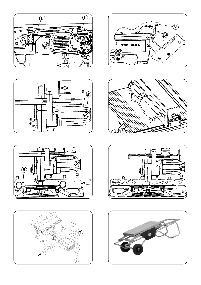
Fig. 18Fig. 17
Fig. 19
Fig. 23
Fig. 21
Fig. 20
Fig. 22
Fig. 24
43
Page 44

4396348 052012
Virutex, S.A.
Antoni Capmany, 1
08028 Barcelona (Spain)
www.virutex.es
 Loading...