

Page 1
RC52P
MANUAL DE INSTRUCCIONES
OPERATING INSTRUCTIONS
GEBRAUCHSANWEISUNG
ИНСТРУКЦИЯ ПО ЭКСПЛУАТАЦИИ
Recortador de cantos
End trimmer
Kappvorrichtung
Торцевой подрезатель для стыковки кромочного материала
Page 2
2
ESPAÑOL Recortador de cantos RC52P
3
ENGLISH RC52P End trimmer
4
DEUTSCH Kappvorrichtung RC52P
5
РУССКИЙ RC52P Торцевой подрезатель для стыковки кромочного материала
6
página/page
seite/ страница
MANUAL DE INSTRUCCIONES
OPERATING INSTRUCTIONS
GEBRAUCHSANWEISUNG
ИНСТРУКЦИЯ ПО ЭКСПЛУАТАЦИИ
Fig. 1 Fig. 2
Page 3
3
RECORTADOR DE CANTOS RC52P
IMPORTANTE
¡ATENCIÓN! Antes de utilizar la máquina lea aten-
tamente éste MANUAL DE INSTRUCCIONES y
el FOLLETO DE INSTRUCCIONES GENERALES
DE SEGURIDAD que se adjunta.
Asegúrese de haberlos comprendido antes de
empezar a operar con la máquina.
Conserve los dos manuales de instrucciones para
posibles consultas posteriores.
1. CARACTERÍSTICAS TÉCNICAS
Ancho máximo de corte.............................55 mm
Grueso máximo de corte..........................1,7 mm
Peso........................................................ 0,87 kg
2. DESCRIPCIÓN
El recortador de cantos RC52P, permite obtener
un buen acabado en las uniones solapadas, en
chapados de cantos, tanto en rectos como siluetas
curvas.
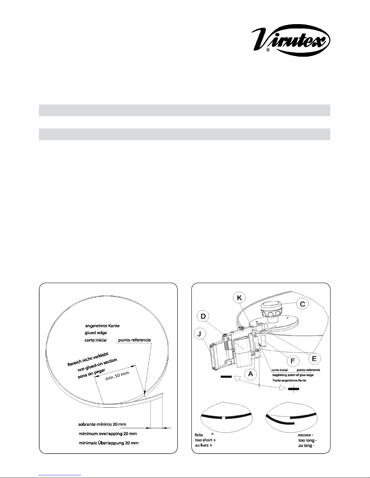
3. PREPARACION DEL CANTO
Hacer un corte inicial del canto, para disponer de
una buena cara de referencia.
Corte la longitud del canto deseado más un exceso
no inferior a 20 mm (Fig. 1), para garantizar un
buen solape.
Pegue el canto en el tablero, dejando al nal un
mínimo de 50 mm de canto sin pegar, con el n
de poder colocar el recortador.
4. SITUACION Y UTILIZACION DEL
RECORTADOR
Colocar el recortador de cantos, apoyado sobre
la supercie del tablero (Fig. 2), introduciendo el
extremo del canto sin pegar, por la guía B (Fig. 3),
y las cuchillas (Fig. 2).
Desplazar el recortador, hasta que toque el punto
de referencia del canto pegado (Fig. 2), y el tope
F, toque en la supercie del canto.
Proceder al corte sujetando el recortador con
una mano sobre el pomo C (Fig. 2), y con la otra
presionar la palanca de corte J, procurando no
perder el punto de referencia ni el apoyo del tablero.
5. FIJACION DEL AJUSTE DEL SOLAPE DEL
CANTO PARA CORTES SUCESIVOS
¡ATENCION! El recortador no esta ajustado de
fábrica, por lo que es necesario un ajuste previo.
Repita la operación del apartado 4. Desenroscar
el pomo E (Fig. 2), que permite desplazar el
palpador F, hasta hacer contacto con la cara del
canto pegado, efectuar un leve movimiento de
giro según convenga en el sentido de las echas
indicadas (Fig. 2), para ajustar la precisión del
solape, roscar nuevamente el pomo con rmeza,
quedando ajustado para repetidos cortes del canto.
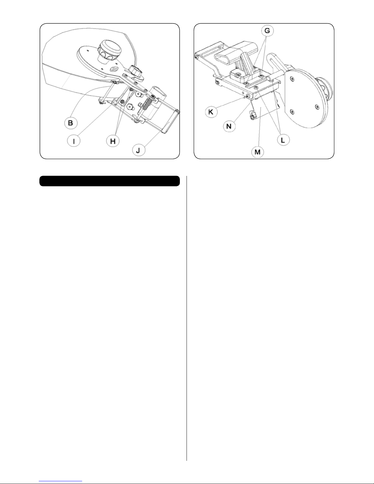
6. SUSTITUCIÓN DE LAS CUCHILLAS
6.1. CUCHILLA DESPLAZABLE
Desenroscar los dos tornillos G, (Fig. 4), con sus
dos tuercas H, (Fig. 3), y las dos arandelas, retirar
la guia I, (Fig. 3), quedando accesible la cuchilla.
Limpiar los restos de cola y suciedad. Alar o
sustituir la cuchilla, y proceder a su montaje, en
operación inversa, comprobando su buen deslizamiento, presionado la maneta J, (Fig. 3).
Español
Fig. 3 Fig. 4
Page 4

4
4. PLACEMENT AND USE OF THE TRIMMER
Rest the edge trimmer on the surface of the board
(Fig. 2), introducing the unstuck end of the edge
through guide B (Fig. 3), and the blades (Fig. 2).
Move the trimmer until it makes contact with the
reference point of the stuck edge (Fig. 2), and stop
F touches the surface of the edge.
Start cutting, holding the trimmer with one hand
on knob C (Fig. 2), and with the other hand, press
down on cutting lever J, endeavouring not to lose
the reference point or the support of the board.
5. SETTING THE EDGE OVERLAP FOR FURTHER CUTS
WARNING! The trimmer is not factory-set, so it
must be adjusted before use.
Repeat the operation in section 4. Unscrew knob
E (Fig. 2), which allows you to move feeler F, until
it makes contact with the stuck edge, then turn
slightly in the direction of the arrows (Fig. 2), to
adjust the precision of the overlap, then screw
the knob rmly once again. It is now adjusted for
repeated edge cutting.
6. REPLACING THE BLADES
6.1. MOVEABLE BLADE
Unscrew the two screws G, (Fig. 4), with the two
nuts H, (Fig. 3), and the two washers; remove
guide I, (Fig. 3), thus leaving the blade accessible.
Clean off any remaining glue and dirt. Sharpen or
replace the blade and then reassemble it, taking
the above steps in reverse, making sure it moves
correctly, pressing on lever J, (Fig. 3).
6.2. FIXED BLADE
Unscrew the two screws K, (Fig. 2 and 4), the two
screws L, with the two nuts and the two washers,
and remove guide M, together with its base N,
(Fig. 4), thus leaving the blade accessible. Clean
off any remaining glue and dirt. Sharpen or replace
the blade and then reassemble it, taking the above
steps in reverse.
When the blade has been replaced, ensure that it
is cutting correctly across the whole width.
7. WARRANTY
All VIRUTEX power tools are guaranteed for 12
months from the date of purchase, excluding any
damage which is a result of incorrect use or of
natural wear and tear on the machine. All repairs
should be carried out by the ofcial VIRUTEX
technical assistance service.
VIRUTEX reserves the right to modify its products
without prior notice.
6.2. CUCHILLA FIJA
Desenroscar los dos tornillos K, (Fig. 2 y 4), los dos
tornillos L, con sus dos tuercas, y las dos arandelas,
y retirar el canalizador M, junto con su base N,
(Fig. 4), quedando accesible la cuchilla. Limpiar
los restos de cola y suciedad. Alar o sustituir la
cuchilla, y proceder a su correcto montaje en su
alojamiento en operación inversa.
Comprobar una vez montadas, el buen funcionamiento de corte en su ancho total.
7. GARANTIA
Todos los productos VIRUTEX, tienen una garantía
válida de 12 meses a partir del día de su suministro,
quedando excluidas todas las manipulaciones o
daños ocasionados por manejos inadecuados o
por desgaste natural.
Para cualquier reparación dirigirse al servicio ocial
de asistencia técnica VIRUTEX.
VIRUTEX, S.A. se reserva el derecho de modicar
sus productos sin previo aviso.
English
RC52P END TRIMMER
WARNING
CAUTION. Read these OPERATING INSTRUC-
TIONS and the attached GENERAL SAFETY
INSTRUCTIONS LEAFLET carefully before using
the machine. Make sure you have understood them
before operating the machine for the rst time.
Keep both sets of instructions for any future queries.
1. SPECIFICATIONS
Maximum cut width....................................55 mm
Maximum cut thickness.............................1.7 mm
Weight........................................................0.87 kg
2. DESCRIPTION
The RC52P edge trimmer gives a good nish on
overlapping joints and on veneered edges, both
for straight lines and curves.
3. PREPARING THE EDGE
Make an initial cut in the edge to give you a good
reference point.
Cut the required length of the edge, plus an excess of at least 20 mm (Fig. 1), to guarantee a
good overlap.
Stick the edge to the board, leaving an unstuck
area at the end of at least 50 mm for placement
of the trimmer.
Page 5

5
Deutsch
KAPPVORRICHTUNG RC52P
ACHTUNG!
Wichtiger Hinweis: Lesen Sie bitte vor Benut-
zung der Maschine die beiliegende GEBRAUCHSANWEISUNG und die ALLGEMEINEN
SICHERHEITSHINWEISE sorgfältig durch.
Stellen Sie sicher, dass Sie sowohl die Gebrauchsanweisung als auch die allegemeinen Sicherheitshinweise verstanden haben, bevor Sie die
Maschine bedienen. Bewahren Sie beide Gebrauchsanweisungen zum späteren Nachschlagen auf.
1. TECHNISCHE DATEN
Maximale Schnittbreite..............................55 mm
Maximale Schnittstärke............................1,7 mm
Gewicht...................................................0,87 kg
2. BESCHREIBUNG
Der Kantenschneider RC52P ermöglicht eine
hochwertige Ausführung überlappender Verbindungen sowohl von geraden als auch von gebogenen
Kantenfurnieren.
3. VORBEREITUNG DER KANTE
Führen Sie einen ersten Kantenschnitt aus, um
eine gute Bezugsseite zu erhalten.
Schneiden Sie die Kante auf die gewünschte Länge
zu und lassen Sie dabei eine Überlänge von mindestens 20 mm, (Abb. 1), um eine ausreichende
Überlappung zu gewährleisten.
Kleben Sie die Kante auf die Platte. Lassen Sie
dabei am Ende ein nicht festgeklebtes Stück von
mind. 50 mm Länge zum Ansetzen des Kantenschneiders übrig.
4. POSITION UND EINSATZ DES KANTENSCHNEIDERS
Setzen Sie den Kantenschneider auf die Oberäche der Platte (Abb. 2) und führen Sie das nicht
festgeklebte Ende der Kante in die Führung B (Abb.
3) entlang der Messer (Abb. 2) ein.
Schieben Sie den Kantenschneider bis zum Bezugspunkt der geklebten Kante (Abb. 2), sodass
der Anschlag F die Oberäche der Kante berührt.
Führen Sie den Schnitt aus. Halten Sie dazu den
Kantenschneider mit einer Hand am Griff C (Abb.
2) und drücken Sie mit der anderen Hand auf den
Schneidhebel J. Achten Sie dabei darauf, weder
den Kontakt zum Bezugspunkt noch zur Platte
zu verlieren.
5. FIXIERUNG DER EINSTELLUNG DES
KANTENÜBERSTANDS FÜR MEHRFACHE
SCHNITTE
ACHTUNG! Der Kantenschneider ist werkseitig
nicht eingestellt und muss daher vor Verwendung
justiert werden.
Wiederholen Sie die in Absatz 4 beschriebenen
Schritte. Drehen Sie den Griff E heraus (Abb.
2) und verstellen Sie den Fühler F, bis er an der
Fläche der geklebten Kante ansteht. Führen Sie je
nach Bedarf eine Drehbewegung in Richtung der
Pfeile (Abb. 2) aus, um den Überstand exakt einzustellen. Danach schrauben Sie den Griff wieder
fest. Nun ist der Kantenschneider für mehrfache
Kantenschnitte eingestellt.
6. AUSTAUSCHEN DER MESSER
6.1. VERSTELLBARES MESSER
Schrauben Sie beiden Schrauben G (Abb. 4) mit
den beiden Muttern H (Abb. 3) und den beiden
Unterlegscheiben auf und nehmen Sie die Führung
I (Abb. 3) ab, sodass das Messer zugänglich wird.
Entfernen Sie Kleberreste und Schmutz. Schleifen
bzw. ersetzen Sie das Messer und bauen Sie es in
umgekehrter Reihenfolge wieder ein. Überprüfen
Sie durch Druck auf den Griff J (Abb. 3), ob sich
das Messer richtig bewegen lässt.
6.2. FESTSTEHENDES MESSER
Schrauben Sie beiden Schrauben K (Abb. 2 und
4) sowie die beiden Schrauben L mit den beiden
Muttern und den beiden Unterlegscheiben auf
und nehmen Sie die Führung M mit der Auage N
(Abb. 4) ab, sodass das Messer zugänglich wird.
Entfernen Sie Kleberreste und Schmutz. Schleifen
bzw. ersetzen Sie das Messer und bauen Sie es
in umgekehrter Reihenfolge wieder ein.
Überprüfen Sie nach dem Einbau der beiden Messer deren einwandfreien Schnitt über die gesamte
Messerbreite.
7. GARANTIE
Alle tragbaren Elektrogeräte von VIRUTEX haben
eine Garantie von 12 Monaten ab dem Lieferdatum.
Hiervon ausgeschlossen sind alle Eingriffe oder
Schäden aufgrund von unsachgemäßem Gebrauch
oder natürlicher Abnutzung des Geräts. Wenden
Sie sich im Falle einer Reparatur immer an den
zugelassenen Kundendienst von VIRUTEX.
VIRUTEX behält sich das Recht vor, die Produkte
ohne vorherige Ankündigung zu verändern.
Page 6

6
Русский
RC52P ТОРЦЕВОЙ ПОДРЕЗАТЕЛЬ ДЛЯ
СТЫКОВКИ КРОМОЧНОГО МАТЕРИАЛА
ПРЕДУПРЕЖДЕНЕ
Пред началом эксплуатации оборудования
внимательно прочитайте данную
ИНСТРУКЦИЮ ПО ЭКСПЛУАТАЦИИ и
прилагаемую ОБЩУЮ ИНСТРУКЦИЮ
ПО ТЕХНИКЕ БЕЗОПАСНОСТИ. Перед
применением инструмента в первый раз
убедитесь в том, что все изложенное в данных
документах Вам понятно. Сохраните комплект
документации для обращения к ней в будущем.
1. ТЕХНИЧЕСКИЕ ХАРАКТЕРИСТИКИ
Максимальная ширина реза...............55 мм
Максимальная толщина реза…........1.7 мм
Вес………………..................................0.87 кг
2. ОПИСАНИЕ И ОБЛАСТЬ ПРИМЕНЕНИЯ
Торцевой подрезатель RC52P обеспечивает
качественную стыковку торцов кромочного
материала при необходимости его
приклеивания встык как на прямолинейных,
так и на криволинейных деталях.
3. ПОДГОТОВКА КРОМОЧНОГО МАТЕРИАЛА
Для обеспечения правильной стыковки
перед началом приклейки отторцуйте
кромочный материал. Отрежьте кромочный
материал требуемой длины с припуском
не менее 20 мм (Fig. 1) для обеспечения
его приклейки «внахлест». Осуществите
приклейку кромочного материала, оставив
не приклеенным участок длиной не менее 50
мм, для установки подрезателяr.
4. УСТАНОВКА И ИСПОЛЬЗОВАНИЕ
ТОРЦЕВОГО ПОДРЕЗАТЕЛЯ
Установите торцевой подрезатель на
обрабатываемой панели (Fig. 2), пропустив не
приклеенный конец кромочного материала под
направляющей B (Fig. 3), между ножами (Fig. 2).
Сдвиньте подрезатель до его контакта с уже
приклеенным торцом кромочного материала
(Fig. 2), при этом ограничитель F должен
касаться поверхности кромочного материала.
Начните удаление излишка кромочного
материала, удерживая подрезатель одной
рукой за рукоятку C (Fig. 2), а другой, нажимая
на рукоятку привода ножа J. При удалении
излишка кромочного материала не теряйте
контакт подрезателя с уже приклеенным
торцом кромочного материала или деталью.
5. НАСТРОЙКА ОБЛАСТИ ПЕРЕКРЫТИЯ
ДЛЯ ВЫПОЛНЕНИЯ РЕЗОВ
ВНИМАНИЕ! Торцевой подрезатель нуждается
в настройке перед его применением.
Выполните операции, изложенные в разделе
4. Отверните фиксатор E (Fig. 2), что позволит
Вам перемещать ограничитель F, до его
касания с уже приклеенным кромочным
материалом. Настройка осуществляется
наклоном подрезателя в соответствии с
направлением стрелки (Fig. 2), до достижения
требуемого результата стыковки, затем
надежно затяните фиксатор E (Fig. 2). Теперь
подрезатель настроен и готов к работе.
6. ЗАМЕНА НОЖЕЙ
6.1. ПОДВИЖНЫЙ НОЖ
Отверните два винта G, (Fig. 4) с двумя
гайками H, (Fig. 3) и двумя шайбами;
демонтируйте упор I, (Fig. 3), освобождая,
таким образом, нож. Очистите посадочное
место ножа от пыли и остатков клея. Заточите
или замените нож. Осуществите сборку
в обратном порядке. Нажимая на привод
ножа J (Fig. 3) убедитесь в том, что нож
перемещается правильно.
6.2. НЕПОДВИЖНЫЙ НОЖ
Отверните два винта K, (Fig. 2 and 4),
два винта L, с двумя гайками и шайбами,
после чего демонтируйте упор M, вместе с
основанием N, (Fig. 4), освобождая, таким
образом, нож. Очистите посадочное место
ножа от пыли и остатков клея. Заточите или
замените нож. Осуществите сборку в обратном
порядке. После замены ножа убедитесь в том,
что нож режет правильно по всей его длине.
7. ГАРАНТИЙНЫЕ ОБЯЗАТЕЛЬСТВА
Все инструменты фирмы Virutex имеют
гарантию 12 месяцев со дня покупки.
Гарантия не распространяется на те
случаи, когда повреждение явилось
результатом неправильной эксплуатации или
естественного износа. При необходимости
ремонта обращайтесь в пункты
техобслуживания или уполномоченным
представителям фирмы Virutex.
Компания VIRUTEX оставляет за собой
право вносить изменения в конструкцию
или стандартный комплект поставки без
предварительного уведомления.
Page 7

Page 8

Virutex, S.A.
Antoni Capmany, 1
08028 Barcelona (Spain)
www.virutex.es
5296452 092014
http://www.virutex.es/registre
Acceda a toda la información técnica.
Access to all technical information.
Accès à toute l’information technique.
Zugang zu allen technischen Daten.
Accedere a tutte le informazioni tecniche.
Aceso a todas as informações técnicas.
Dostęp do wszystkich informacji technicznych.
Доступ ко всей технической информации.
 Loading...