

Page 1
MANUAL DE INSTRUCCIONES
OPERATING INSTRUCTIONS
MODE D’ EMPLOI
GEBRAUCHSANWEISUNG
MANUALE D’ISTRUZIONI
MANUAL DE INSTRUÇÕES
ИНСТРУКЦИЯ ПО ЭКСПЛУАТАЦИИ
INSTRUKCJA OBSŁUGI
RA17 VB
Fresadora Ranuradora
Grooving Machine
Fraiseuse à Rainures
Nutenfräsmaschine
Fresatrice Scanalatrice
Fresadora Ranhuradora
Фрезер для пазов
Żłobiarka
Page 2
MANUAL DE INSTRUCCIONES
OPERATING INSTRUCTIONS
MODE D'EMPLOI
GEBRAUCHSANWEISUNG
MANUALE D'ISTRUZIONI
MANUAL DE INSTRUÇÕES
ИНСТРУКЦИЯ
INSTRUKCJA OBSŁUGI
ПО
ЭКСПЛУАТАЦИИ
página/page
seite/pagina
страница/strona
ESPAÑOL Fresadora Ranuradora RA17 VB
ENGLISH RA17 VB Grooving Machine
FRANÇAIS Fraiseuse à rainures RA17 VB
DEUTSCH Nutenfräsmaschine RA17 VB
ITALIANO Fresatrice Scanalatrice RA17 VB
PORTUGUÉS Fresadora Ranhuradora RA17 VB
РУССКИЙ Фрезер для пазов RA17 VB
РOLSKI RA17 VB Żłobiarka
Fig. 1
1
5
7
9
11
14
16
18
21
9
2
5
4
7
8
3
2
6
Page 3

Fig. 2
A
B
Fig. 4
Fig. 6
Fig. 3
C
C
D
D
F
Fig. 5
H
E
Fig. 7
G
3
Page 4
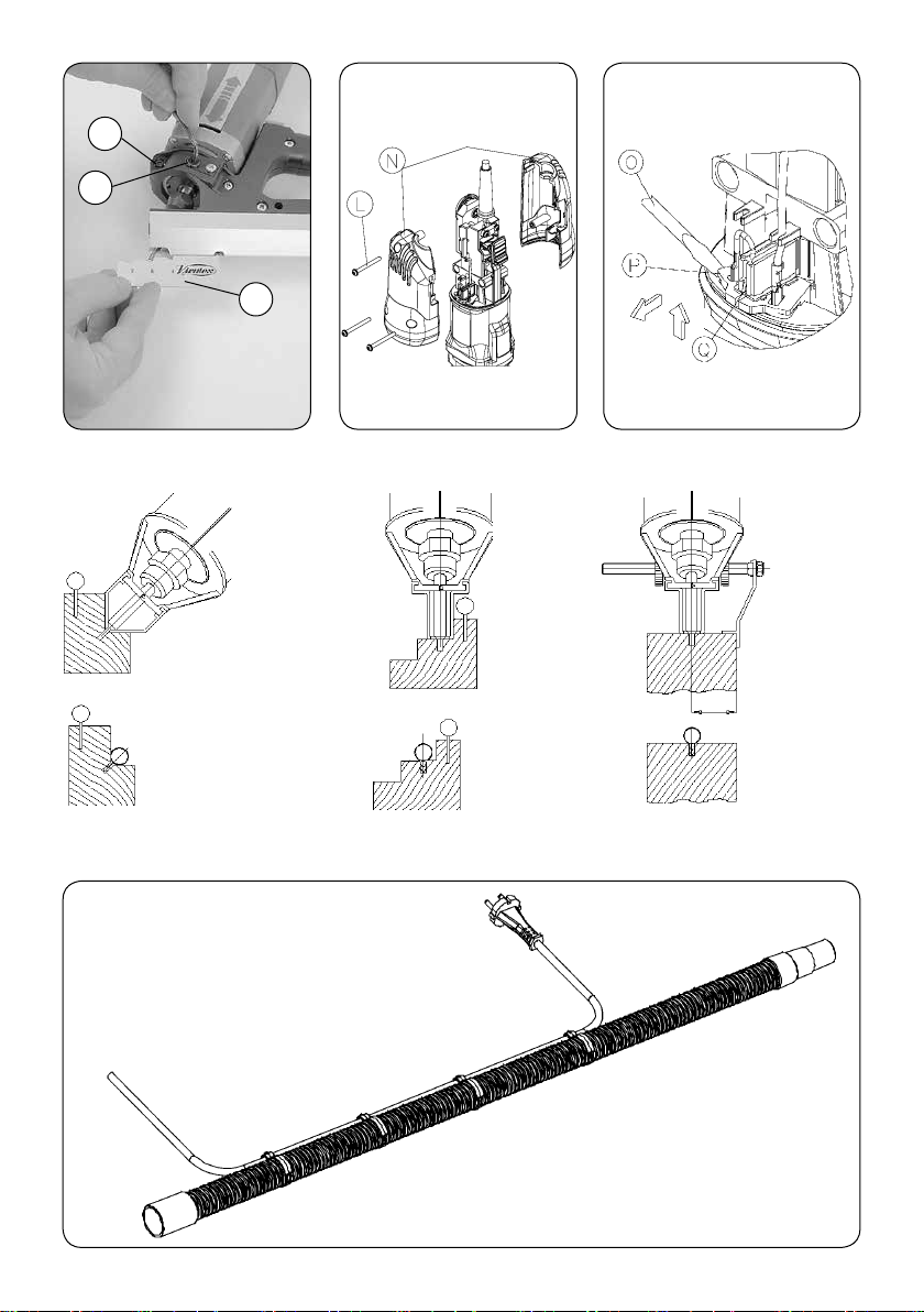
Fig. 9 Fig. 10
K
I
J
Fig. 8
52 mm.
máximo
Fig. 11
4
Fig. 12 Fig. 13
Fig. 14
Page 5
Ø Ø
Fresa Caña Mod.Junta N.stock junta N.stock fresa M.D. N.stock rodillo Profundidad fresado
Miller Shaft Joint Model Joint stock nº H.M Miller stock nº Roller stock nº Milling depth
Fraise Corps Modele Joint Nºstock joint Nºstock fraise M.D. Nºsotck rouleau Profondeur de fraisage
Fräse Schaft Dichtungsmodell Largernr.Dichtung Largernr.H.M fräse Lagernr.Rolle Frästiefe
Fresa Gambo Mod.guarnizione Nºstock guarnizione Nºstock fresa M.D. Nºstock rullo Profondità fresatura
Fresa Cana Modelo Junta Nºstock junta Nºstock fresa M.D. Nºstock rolo Profundidade da corte
3 6 FS1 1204081 1740103 1746158 6 mm.
3 6 FS1/B 1204181 1740103 1746158 6 mm.
Esp
Spec
Spez 6 FS2 1204082 1740104 1746158 6 mm.
Esp
Spec
Spez 6 FS2/B 1204182 1740104 1746158 6 mm.
Fig. 15
ESPAÑOL
FRESADORA RANURADORA RA17 VB
1. INSTRUCCIONES DE SEGURIDAD
PARA EL MANEJO DE LA RANURADORA
Lea atentamente el FOLLETO DE INSTRUCCIONES GENERALES DE SEGURIDAD,
que se adjunta con la documentación de
la máquina.
1. Asegúrese antes de enchufar la máquina, que la
tensión de alimentación se corresponda con la indicada
en la chapa características.
2. Mantenga siempre las manos alejadas del área de
corte, y sujete siempre la máquina por las empuñaduras.
3. Use siempre herramientas originales VIRUTEX. No
use nunca herramientas defectuosas o en mal estado.
4. Es necesario trabajar con aspiración de la viruta para
prolongar la vida de la fresa y evitar posibles roturas
de la misma.
2. CARACTERÍSTICAS TÉCNICAS
Potencia absorbida....................................630 W
Motor.....................................................50/60 Hz
Revoluciones...................................28.000/min
-1
Pinza fresa.............................................Ø 6 mm
(opcional 12.22.024 pinza Ø 8 mm)
Peso máquina............................................1,95 Kg
Nivel de Presión acústica Ponderado A...............86 dBA
Nivel de Potencia acústica Ponderada A................97 dBA
Incertidumbre de la medición............................K = 3 dBA
¡Usar protectores auditivos!
Nivel total de emisión de vibraciones...........a
Incertidumbre de la medición...........................K: 1,5 m/s
: <2,5 m/s
h
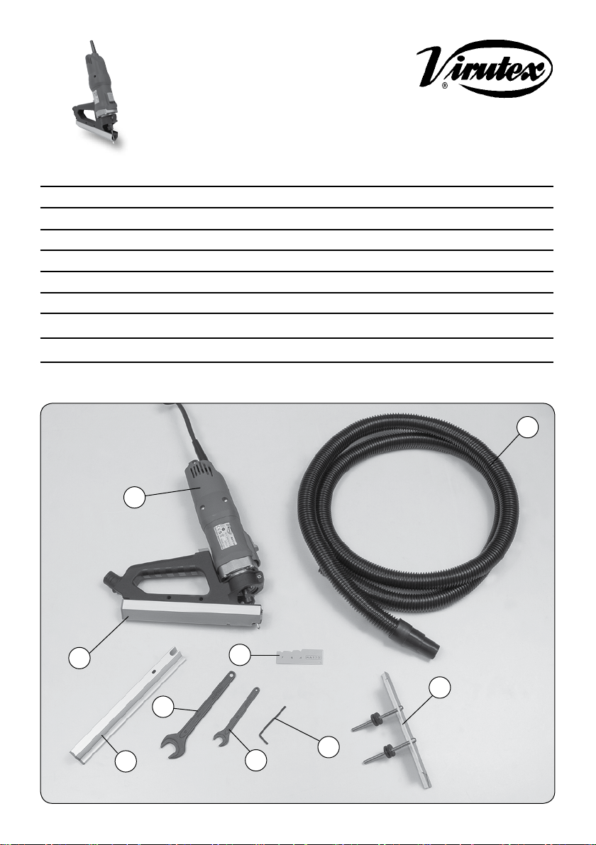
3. EQUIPO ESTÁNDARD
En el interior de la maleta de transporte, Ud. encontrará
los elementos siguientes (Fig. 1):
1.- Fresadora ranuradora RA17 VB con fresa M.D. afilada
en ambas puntas.
2.- Guía 90°.
3.- Guía recta.
4.- Escuadra reversible.
5.- Galga de profundidad.
6.- Llave e/c: 11 mm para eje motor.
7.- Llave e/c: 19 mm para tuerca fijación pinza.
8.- Llave allen e/c: 3 mm.
9.- Tubo aspiración.
10. -Abrazaderas cable-tubo aspiración
11. - Manual instrucciones
4. DESCRIPCIÓN GENERAL
DE LA FRESADORA RA17 VB
La función principal de la máquina es el ranurado de
ventanas y puertas, para la colocación de juntas de
aislamiento. La máquina va equipada con 2 tipos de
guía y una escuadra reversible que permiten realizar
ranuras en diversas posiciones como se explica en los
próximos apartados de este manual. Dispone también,
de un pivote de centraje, que facilita la entrada de la
fresa al principio de la operación. La máquina va provista
de toma para aspiración, por la que puede conectarse,
mediante el TUBO ACOPLAMIENTO ASPIRADOR No. 9
(Fig. 1), a nuestros aspiradores AS182K, AS282K, o a
cualquier aspirador industrial.
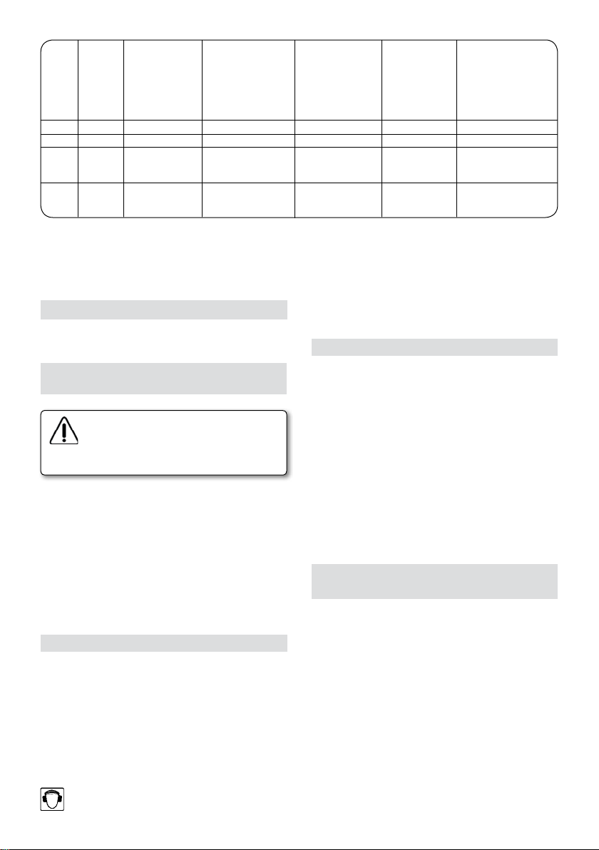
Las abrazaderas que se montan en el tubo de aspiración,
permiten introducir el cable de alimentación a través
de ellas para facilitar el manejo de la máquina. (Fig. 14)
2
2
5
Page 6
5. TIPOS DE FRESADO
Las ranuras pueden realizarse tanto en las partes móviles;
puertas, o ventanas, como en el marco, donde es más
recomendable por su sencillez.
Para controlar la entrada de la fresa en la madera, de
un modo progresivo y centrado, la máquina dispone del
centrador F, que es accionado por el botón E. (Fig. 6).
Para empezar una ranura, se presionará a fondo el botón
E, y se colocará la máquina sobre el elemento a ranurar,
apoyada entre la parte posterior de la guía y el extremo
del centrador F. A continuación y tras la puesta en marcha
de la máquina, soltaremos progresivamente el botón E,
hasta que la fresa se introduzca en la madera, y la guía
de la máquina quede totalmente apoyada, momento
en que podremos iniciar el avance. En el fresado de
ranuras en el marco, y a fin de poder llegar hasta las
esquinas, se iniciará el ranurado en un punto intermedio
del bastidor o travesaño, se ranurará hasta un extremo
y deberá repetirse la operación desde el mismo punto
de inicio, hacia el otro extremo.
5.1 FRESADOS CON GUÍA 90° (Fig. 11)
Se empleará esta guía, para el fresado de ranuras oblicuas
a 45°, en el rebajo de los marcos, o en las ventanas .
5.2 FRESADOS CON GUÍA RECTA (Fig. 12 y 13)
Permite la realización de ranuras rectas, en el rebajo de
los marcos o en las ventanas .
Es posible el ranurado de ventanas, sin necesidad de
desmontar las fijas. (Fig. 12).
Con la ayuda de la escuadra (Fig. 13), pueden realizarse
ranuras en zonas lisas, como el lateral de los pernios en
una puerta, a una distancia regulable desde una cara.
6. CAMBIO DE GUÍAS
El cambio de la guía, (Figs. 2 y 3), se realiza muy fácilmente,
con sólo extraer el tornillo B, que la sujeta y tirar de ella
hacia atrás como muestra la (Fig. 3) hasta su extracción.
La nueva guía se montará de modo análogo.
Al cambiar de guía, se mantiene la profundidad de
fresado, por lo que no suele ser necesario una nueva
regulación de la herramienta.
7. MONTAJE DE LA ESCUADRA REVERSIBLE
La escuadra reversible puede utilizarse por ambos lados
de la máquina. Para su montaje, deben extraerse las dos
tuercas C, (Fig. 4), insertar la escuadra por los orificios
laterales de la máquina, y fijarla en la posición deseada,
sujetándose contra el cuerpo de la máquina, entre las
tuercas C y D, (Fig. 5).
8. CAMBIO DE FRESA
6
Desconecte la máquina de la red eléctrica,
antes de realizar esta operación.
Para el cambio de la fresa (Fig. 7), bloquee el eje motor
mediante la llave H, desenrosque la tuerca con la llave G
y extraiga la fresa. Introduzca la nueva Fresa, hasta que
la punta de la misma, quede a 43 ±1 mm de la cara de la
tuerca y apriete esta de nuevo con la ayuda de la llaves.
Las fresas suministradas por VIRUTEX, están afiladas por
ambos extremos.
9. REGULACIÓN DE LA
PROFUNDIDAD DE FRESADO
Aflojar el tornillo K (Fig. 8), hasta que el motor pueda
moverse con las manos. Seguidamente girar la excéntrica
I con la llave de servicio, hasta conseguir la medida
deseada con la ayuda de la galga J y una vez obtenida
esta, apretar de nuevo el tornillo K.
10. JUNTAS
Se aconseja el empleo de las JUNTAS DE CAUCHO DE
SILICONA VIRUTEX, por su excelente resistencia a la
intemperie y sus propiedades elásticas bajo carga, a
temperaturas entre -60°C y 200°C.
Tipos de juntas:
..............
1204081 Modelo FS1 1204082 Modelo FS2
color marrón Ø 8 mm color marrón Ø 8 mm
1204181 Modelo FS1/B 1204182 Modelo FS2/B
color blanco Ø 8 mm color blanco Ø 8mm
Cada tipo de junta necesita el empleo de la fresa adecuada. Consultar en la tabla los distintos tipos de fresa.
Para colocar las juntas en las ranuras con facilidad se
aconseja la utilización del RODILLO JUNTAS SILICONA
(ref. 1746158). (Fig. 15)
11. MANTENIMIENTO DE
ESCOBILLAS Y COLECTOR
Desconecte la máquina de la red eléctrica,
antes de efectuar cualquier operación de
mantenimiento.
Quitar los tornillos L (Fig. 9) que sujetan las tapas laterales
N y separar ambas.
Extraer los portaescobillas P (Fig. 10) con la ayuda de un
Page 7

pequeño destornillador O, haciendo palanca sobre una
de las pestañas laterales del portaescobillas.
Desplazar hacia atrás el extremo del muelle Q. Retenerlo
en esta posición para extraer la escobilla y sustituirla
por una nueva original Virutex. Colocar de nuevo el
portaescobillas procurando que asiente firmemente en
la carcasa y que cada una de las escobillas presionen
suavemente sobre el colector.
Montar las tapas N con sus correspondientes tornillos,
asegurándose de no pellizcar ningún cable en el ensamblaje de ambas.
Es aconsejable que se tenga en marcha durante unos 15
minutos la máquina una vez cambiadas las escobillas.
Si el colector presenta quemaduras o resaltes, se recomienda hacerlo reparar en un servicio técnico VIRUTEX.
Mantenga siempre el cable y el enchufe en buenas
condiciones de servicio.
12. NIVEL DE RUIDOS
Los niveles de ruido y vibraciones de esta herramienta
eléctrica han sido medidos de acuerdo con la Norma
Europea EN 60745-2-17 y EN 60745-1 y sirven como base
de comparación con máquinas de semejante aplicación.
El nivel de vibraciones indicado ha sido determinado
para las aplicaciones principales de la herramienta,
y puede ser utilizado como valor de partida para la
evaluación de la exposición al riesgo de las vibraciones.
Sin embargo, el nivel de vibraciones puede llegar a ser
muy diferente al valor declarado en otras condiciones
de aplicación, con otros útiles de trabajo o con un
mantenimiento insuficiente de la herramienta eléctrica
y sus útiles, pudiendo llegar a resultar un valor mucho
más elevado debido a su ciclo de trabajo y modo de uso
de la herramienta eléctrica.
Por tanto, es necesario fijar medidas de seguridad de
protección al usuario contra el efecto de las vibraciones,
como pueden ser mantener la herramienta y útiles de
trabajo en perfecto estado y la organización de los
tiempos de los ciclos de trabajo (tales como tiempos
de marcha con la herramienta bajo carga, y tiempos de
marcha de la herramienta en vacío y sin ser utilizada
realmente ya que la reducción de estos últimos puede
disminuir de forma sustancial el valor total de exposición).
13. GARANTÍA
Todas las máquinas electroportátiles VIRUTEX tienen
una garantía válida de 12 meses a partir del día de su
suministro, quedando excluidas todas las manipulaciones
o daños ocasionados por manejos inadecuados o por
desgaste natural de la máquina.
Para cualquier reparación dirigirse al servicio oficial de
asistencia técnica VIRUTEX S.A.
VIRUTEX se reserva el derecho de modificar sus productos
sin previo aviso.
ENGLISH
RA17 VB GROOVING MACHINE
1. SAFETY INSTRUCTIONS FOR
USE OF THE GROOVING MACHINE
Read carefully the GENERAL SAFETY INSTRUCTIONS LEAFLET, which is included
in the machine documentation.
1. Before starting up the machine make sure that the
supply voltage is the same as that shown on the specification plate.
2. Always keep hands clear of the cutting area, and
always hold the machine using the grips.
3. Always use original VIRUTEX tools. Never use damaged
tools or tools in poor condition.
4. It's advisable to work with dust collection in order to
avoid the bit's break.
2. TECHNICAL CHARACTERISTICS
Imput Power..............................................630W
Motor....................................................50/60 Hz
No load speed...................................28,000/min
Chuck collet.............................................Ø 6 mm
Weight......................................................1.95 kg
Weighted equivalent continuous
acoustic pressure level A.......................................86 dBA
Acoustic power level A...............................................97 dBA
Uncertainty..............................................................K = 3 dbA
Wear ear protection!
Vibration total values.......................................ah: <2.5 m/s
Uncertainty..........................................................K: 1.5 m/s
3. STANDARD EQUIPMENT
Contained in the transportation case you will find the
following elements (Fig. 1):
1.- Grooving machine RA17 VB with carbide bit sharpened at both ends.
2.- 90° guide.
3.- Straight guide.
4.- Reversible angle.
5.- Depth gauge.
6.- Size 11 mm key for motor shaft
7.- Size 19 mm key for securing clamp.
8.- Size 3 mm Allen key.
9.- Dust collection pipe
10.- Cable – dust collection tube brackets
11.- Instruction manual
-1
2
2
7
Page 8
4. GENERAL DESCRIPTION
OF THE RA17 VB MILLING MACHINE
The main function of the machine is to make grooves
and windows in doors for inserting isolation seals.
The machine is equipped with 2 kinds of guide and a
reversible angle that enable the making of grooves in
various positions as explained in the following sections
of this manual. It also has a centering pivot which facilitates the entry of the bit at the start of the operation.
The machine is also equipped with a suction nozzle
which can be used for connection to our AS182K,
AS282K aspirators or any industrial equivalent via the
ASPIRATOR CONNECTION TUBE No. 9 (Fig. 1).
The power cable can be fed through the brackets on
the dust collection tube to make the machine easier
to handle (Fig. 14).
by removing screw B which holds it in place and pulling
it back as shown in (Fig. 3) until it has been removed.
The new guide is inserted in the same way.
On changing the guide, the depth of the groove is
maintained, which means that re-adjustment of the
tool is not usually required.
7. MOUNTING THE REVERSIBLE ANGLE
The reversible angle can be used for both sides of
the machine. For its assembly the 2 screws C must be
removed, (Fig. 4). Insert the reversible angle in the side
openings on the machine and secure it where desired by
supporting it against the body of the machine between
screws C and D. (Fig. 5).
8. CHANGING THE MILLER
5. TYPES OF MILLING
The grooves can be made in the moveable parts of
doors and windows as well as in the frames, which is
recommended for its simplicity. To control the gradual,
centered entry of the miller in the wood the machine
has a centering attachment F which is activated using
button E, (Fig. 6).
To begin a groove button E is pressed to the bottom,
and the machine is placed over the piece to be grooved,
supported by the rear part of the guide and the end of
the centering attachment F. Next, after starting up the
machine, button E is gradually released until the miller
is introduced in the wood and the guide is completely
supported, at which time we can begin moving forward.
In making the groove in the frame in order to reach into
the corners begin grooving at an intermediate point on
the frame or crosspiece. Make the groove to one end
then repeat the operation from the same starting point
working towards the other end.
5.1 GROOVES WITH 90° GUIDE (Fig. 11)
This guide is used for making grooves angled at 45° in
the cut-outs of frames or in windows.
5.2 GROOVES WITH STRAIGHT GUIDE
(Fig. 12 and 13)
Used for making straight grooves in the cut-outs of
frames or in windows.
It is possible to groove windows without having to
dismantle the fixed ones. (Fig. 12).
Using the angle, (Fig. 13), grooves can be made on smooth
areas such as the side of the hinges on the door at a
distance which can be adjusted from one side.
6. CHANGING THE GUIDES
Changing the guide (Figs. 2 and 3) is easily carried out
8
Disconnect the machine from the mains
before carrying out this operation.
To change the miller (Fig. 7) block the motor shaft using
key H, unscrew the bolt with the key G and remove
the bit. Insert the new miller until its tip is within 43
± 1mm from the face of the bolt and re-tighten this
using the key.
The millers supplied by VIRUTEX are sharpened at both
ends.
9. CONTROLLING THE DEPTH OF THE GROOVE
Loosen screw K (Fig. 8) until the motor can be moved
by hand. Next turn the eccentric I with the service key
until the required measurement is obtained with the
help of the gauge J. When obtained re-tighten bolt K.
10. JOINTS
The use of VIRUTEX SILICON RUBBER JOINTS is recommended for their high resistance to bad weather and
elasticity under load at temperatures between -60° C
and 200° C.
Types of joints:
..............
1204081 Model FS1 1204082 Model FS2
brown Ø 8mm. brown Ø 8mm.
1204181 Model FS1/B 1204182 Model FS2/B
white Ø 8mm. White Ø 8mm.
Each type of joint requires the use of the correct bit.
Refer to the table for the different types of bit.
Page 9

To easily position the joints in the grooves we recommend
the use of SILICON JOINT ROLLERS (ref. 1746158). (Fig. 15)
11. MAINTENANCE OF THE
BRUSHES AND COLLECTOR
for 12 months from the date of supply, excluding any
damage which is a result of incorrect use or of natural
wear and tear on the machine.
All repairs should be carried out by the official VIRUTEX
technical assistance service.
Disconnect from the mains before carrying out any maintenance operations.
Remove the screws L (Fig. 9) that hold the side covers
N and detach them from each other.
Remove the brush-holder P (Fig. 10) with small screwdriver O, using one of the brush-holder side tabs to
lever it out. Push back the end of spring Q. Keep it in
this position to extract the brush and replace it with a
new genuine Virutex brush. Re-insert the brush-holder,
ensuring that it is firmly positioned in the casing and that
each of the brushes exerts a small amount of pressure
on the collector.
Re-attach the covers N with the corresponding screws,
making sure that no wires get caught in the process.
It is advisable to leave the machine running for 15
minutes once the brushes have been changed.
If the collector burns or juts out, it should be serviced
by a VIRUTEX service technician.
Always keep the lead and plug in good working condition.
12. NOISE LEVEL
The noise and vibration levels of this device have been
measured in accordance with European standard EN
60745-2-17 and EN 60745-1 and serve as a basis for comparison with other machines with similar applications.
The indicated vibration level has been determined for
the device’s main applications and may be used as an
initial value for evaluating the risk presented by exposure to vibrations. However, vibrations may reach levels
that are quite different from the declared value under
other application conditions, with other tools or with
insufficient maintenance of the electrical device or its
accessories, reaching a much higher value as a result
of the work cycle or the manner in which the electrical
device is used.
Therefore, it is necessary to establish safety measures
to protect the user from the effects of vibrations, such
as maintaining both the device and its tools in perfect
condition and organising the duration of work cycles
(such as operating times when the machine is subjected
to loads, and operating times when working with no-load,
in effect, not in use, as reducing the latter may have a
considerable effect upon the overall exposure value).
13. GUARANTEE
All of VIRUTEX portable electrical goods are guaranteed
VIRUTEX reserves the right to modify its products
without prior notice.
FRANÇAIS
FRAISEUSE À RAINURES RA17 VB
1. INSTRUCTIONS DE SÉCURITÉ POUR LE
MANIEMENT DE LA FRAISEUSE A RAINURES
Lire attentivement la BROCHURE
D'INSTRUCTIONS GÉNÉRALES DE SÉCURITÉ, jointe à la documentation de
la machine.
1. Avant de brancher la machine, s'assurer que la tension
d'alimentation correspond à celle indiquée sur la plaque
des caractéristiques.
2. Maintenir toujours les mains éloignées de la zone de
coupe, et prendre toujours la machine par les poignées.
3. Utiliser toujours des outils d'origine VIRUTEX. Ne
jamais utiliser d'outils défectueux ou en mauvais état.
4. Il est necessaire de travailler avec l'aspiration de
poussière pour éviter que la fraise se casse.
2. CARACTÉRISTIQUES TECHNIQUES
Puissance absorbée..................................630 W
Moteur..................................................50/60 Hz
Révolutions.......................................28.000/min
-1
Pince porte-fraise....................................Ø: 6 mm
Poids machine............................................1,9 kg
Niveau de pression acoustique
continu équivalent pondéré A.............................86 dBA
Niveau de puissance acoustique A..........................97 dBA
Incertitude..............................................................K = 3 dbA
Porter une protection acoustique!
Valeurs totales des vibrations......................ah: <2,5 m/s
Incertitude............................................................K: 1,5 m/s
3. ÉQUIPEMENT STANDARD
A l'intérieur de la mallette de transport, vous trouverez
les éléments suivants (Fig. 1):
1.- Fraiseuse à rainures RA17 VB avec fraise carbure
aiguisée aux deux pointes.
2
2
9
Page 10

2.- Guidage 90°.
3.- Guidage droit.
4.- Équerre réversible.
5.- Jauge de profondeur.
6.- Clé o/c: 11 mm pour axe moteur.
7.- Clé o/c: 19 mm pour Écrou fixation pince.
8.- Clé Allen o/c: 3 mm.
9.- Tube aspiration.
10.- Colliers câble – tuyau d’aspiration.
11. - Manuel d’instructions
4. DESCRIPTION GÉNÉRALE
DE LA FRAISEUSE RA17 VB
La machine a pour fonction principale le rainurage de
fenêtres et portes, pour la mise en place de joints isolants.
La machine est équipée de 2 types de guidage et une
équerre réversible qui permettent de réaliser des rainures dans diverses positions comme il est expliqué dans
les paragraphes suivants de ce manuel. Elle dispose
également d'un pivot de centrage, qui facilite l'entrée
de la fraise au début de l'opération. La machine est
équipée d'une prise d'aspiration, où peut être branché,
moyennant LE TUBE D'ACCOUPLEMENT D'ASPIRATEUR
réf. 6446073, notres aspirateurs AS182K, AS282K ou
tout autre aspirateur industriel.
Les colliers à monter sur le tuyau d’aspiration permettent
d’y introduire le câble d’alimentation pour faciliter le
maniement de la machine (Fig. 14).
5. TYPES DE FRAISAGE
Les rainures peuvent être réalisées sur les parties mobiles
des portes ou fenêtres, ainsi que sur l'encadrement, il
est plus recommandé de le faire sur l'encadrement car
cela résulte plus facile.
Pour contrôler l'entrée de la fraise dans le bois, d'une
manière progressive et centrée, la machine dispose du
centreur F, commandé par le bouton E, (Fig. 6).
Pour commencer une rainure, appuyer à fond sur le
bouton E, et placer la machine sur l'élément à rainurer,
appuyée entre la partie postérieure du guidage et
l'extrémité du centreur F. Ensuite et après avoir mis en
marche la machine, il faut lâcher peu à peu le bouton
E, jusqu'à ce que la fraise entre dans le bois et que le
guidage de la machine soit totalement appuyé, on pourra
alors commencer à avancer.
Pour le fraisage de rainures dans l'encadrement, et afin
de pouvoir arriver jusqu'aux coins, on commencera le
rainurage à un point intermédiaire de la huisserie ou du
croisillon, on fera la rainure jusqu'à une extrémité et il
faudra répéter l'opération en partant du même point
de départ, vers l'autre extrémité.
5.1 FRAISAGES AVEC GUIDAGE 90° (Fig. 11)
On emploiera ce guidage, pour le fraisage de rainures
obliques à 45°, sur le délardement des encadrements,
10
ou sur les fenêtres.
5.2 FRAISAGES AVEC
GUIDAGE DROIT (Figs. 12 et 13)
Il permet de réaliser des rainures droites, dans le délardement des encadrements ou sur les fenêtres.
Il est possible de faire le rainurage de fenêtres, sans avoir
à démonter les partie fixes. (Fig. 12).
A l'aide de l'équerre (Fig. 13), on peut réaliser des rainures
dans des zones lisses, comme le côté des gonds sur une
porte, à une distance réglable en partant d'une face.
6. REMPLACEMENT DES GUIDAGES
Le remplacement du guidage, (Figs. 2 et 3), se réalise
très facilement, en enlevant la vis B qui le fixe, et en
le tirant vers l'arrière comme le montre la (Fig. 3) pour
le faire sortir.
Le nouveau guidage se montera de la même manière.
En remplaçant le guidage, la profondeur de fraisage
se maintient, c'est pourquoi il n'est généralement pas
nécessaire de faire un nouveau réglage de la machine.
7. MONTAGE DE L'ÉQUERRE RÉVERSIBLE
Il est possible d'utiliser l'équerre réversible sur les deux
côtés de la machine. Pour son montage, il faut extraire
les deux écrous C, (Fig. 4). Introduire l'équerre dans les
orifices latéraux de la machine et la fixer dans la position
souhaitée, en la fixant contre le corps de la machine
entre les écrous C et D, (Fig. 5).
8. REMPLACEMENT DE LA FRAISE
Débrancher la machine du secteur, avant
de réaliser cette opération.
Pour remplacer la fraise (Fig. 7), bloquer l'axe moteur à
l'aide de la clé H, dévisser l'écrou avec la clé G et extraire
la fraise. Introduire la nouvelle fraise en faisant en sorte
qu'il y ait 43 mm, ± 1mm, entre la face de l'écrou et la
pointe de la fraise et revisser l'écrou à l'aide de la clé.
Les fraises fournies par VIRUTEX, sont aiguisées aux
deux extrémités.
9. RÉGLAGE DE LA PROFONDEUR DE FRAISAGE
Desserrer la vis K, (Fig. 8), jusqu'à ce qu'on puisse
faire bouger le moteur avec les mains. Ensuite tourner
l'excentrique I avec la clé de service, jusqu'à ce qu'on
obtienne la mesure souhaitée à l'aide de la jauge J.
Quand on a obtenu la mesure souhaitée, revisser la vis K.
10. JOINTS
Il est conseillé d'utiliser les JOINTS EN CAOUTCHOUC DE
Page 11

SILICONE VIRUTEX, pour leur excellente résistance aux
intempéries et leur propriétés élastiques sous charge, à
des températures entre -60° C et 200° C.
Types de joints:
..............
1204081 Modèle FS1 1204082 Modèle FS2
marron Ø 8mm. marron Ø 8mm.
1204181 Modèle FS1/B 1204182 Modèle FS2/B
blanc Ø 8mm. blanc Ø 8 mm.
Il faut employer la fraise appropriée pour chaque type de
joint. Consulter sur le tableau les différents types de fraise.
Pour placer facilement les joints dans les rainures, il est
conseillé d'utiliser le ROULEAU JOINTS SILICONE (réf:
1746158). (Fig. 15)
11. ENTRETIEN DE BALAIS ET COLLECTEUR
Débrancher la machine du secteur, avant
d'effectuer toute opération d'entretien.
pris comme valeur de base pour l’évaluation du risque
lié à l’exposition aux vibrations. Toutefois, dans d’autres
conditions d’application, avec d’autres outils de travail
ou lorsque l’entretien de l’appareil électrique et de ses
outils est insuffisant, il peut arriver que le niveau de
vibrations soit très différent de la valeur déclarée, voire
même beaucoup plus élevé en raison du cycle de travail
et du mode d'utilisation de l'appareil électrique.
Il est donc nécessaire de fixer des mesures de sécurité
pour protéger l'utilisateur contre les effets des vibrations,
notamment garder l’appareil et les outils de travail en
parfait état et organiser les temps des cycles de travail
(temps de fonctionnement avec l’appareil en service,
temps de fonctionnement avec l’appareil à vide, sans être
utilisé réellement), car la diminution de ces temps peut
réduire substantiellement la valeur totale d’exposition.
13. GARANTIE
Toutes les machines électro-portatives VIRUTEX, S.A.
ont une garantie valable 12 mois à partir du jour de
la fourniture, en étant exclus toutes manipulations ou
dommages causés par des maniements inadéquats ou
par usure naturelle de la machine.
Pour toute réparation, s'adresser au service officiel
d'assistance technique VIRUTEX, S.A.
Retirer les vis L (Fig. 9) qui fixent les couvercles latéraux
N et les séparer.
Retirer les porte-balais P (Fig. 10) à l'aide d'un petit
tournevis O, en faisant levier sur l'une des languettes latérales du porte-balais. Déplacer vers l'arrière
l'extrémité du ressort Q. Le retenir dans cette position
pour extraire le balai et le remplacer par un balai neuf
d'origine Virutex. Reposer le porte-balais en prenant soin
de bien l'asseoir dans la carcasse, pour que chaque balai
exerce une pression douce sur le collecteur.
Remonter les couvercles N avec les vis correspondantes, en s'assurant de ne pas pincer un câble lors de
l'assemblage des deux couvercles.
Il est recommandé de mettre la machine en marche
pendant 15 minutes après avoir changé les balais.
Si le collecteur présente des brûlures ou des ressauts,
il est recommandé de le faire réparer dans un service
technique VIRUTEX.
Toujours conserver le câble et la prise dans de bonnes
conditions de service.
12. NIVEAU SONORE
Les niveaux de bruit et de vibrations de cet appareil
électrique ont été mesurés conformément à la norme
européenne EN 60745-2-17 et EN 60745-1 et font
office de base de comparaison avec des machines aux
applications semblables.
Le niveau de vibrations indiqué a été déterminé pour
les principales applications de l’appareil, et il peut être
VIRUTEX se réserve le droit de modifier ses produits
sans avis préalable.
DEUTSCH
NUTENFRÄSMASCHINE RA17 VB
1. SICHERHEITSHINWEISE FÜR DIE
BEDIENUNG DER NUTENFRÄSMASCHINE
Lesen Sie bitte aufmerksam die BROSCHÜRE ÜBER ALLGEMEINE SICHERHEITSHINWEISE, die Sie zusammen mit den
Unterlagen der Maschine erhalten haben.
1. Bevor Sie die Maschine anstellen, versichern Sie sich,
daß die Versorgungsspannung der auf dem Typenschild
angegebenen entspricht.
2. Bringen Sie Ihre Hände nie in die Nähe der Schnittfläche
und halten Sie die Maschine immer an den Griffen fest.
3. Verwenden Sie immer Original-VIRUTEX-Werkzeuge.
Verwenden Sie nie fehlerhafte Werkzeuge oder solche,
die in einem schlechten Zustand sind.
4. Um die Lebensdauer der Fräse zu verlängern und zu
verhindern, dass sie möglicherweise zerbricht, muss mit
Spanabsaugung gearbeitet werden.
11
Page 12

2. TECHNISCHE DATEN
Leistungsaufnahme..................................630 W
Motor...................................................50/60 Hz
mdrehungen.................................28.000/min
-1
Fräsenhalterung....................................Ø: 6 mm
Gewicht der Maschine................................1,95 kg
Gewichteter akustischer Dauerdruckpegel A.....86 dBA
Akustischer Druckpegel A....................................97 dBA
Unsicherheit............................................................K = 3 dBA
Gehörschutz tragen!
Schwingungsgesamtwerte............................ah: <2,5 m/s
Unsicherheit........................................................K = 1,5 m/s
2
2
3. STANDARDAUSRÜSTUNG
Im Transportkoffer finden Sie folgende Teile (Abb. 1):
1.- Nutenfräsmaschine RA17 VB mit einer an beiden
Enden geschärften Fräse.
2.- 90°-Führung
3.- Gerade Führung
4.- Umkehrbarer Winkel
5.- Tiefenlehre
6.- Schlüssel mit Weite von 11 mm, für die Motorachse
7.- Schlüssel mit Weite von 19 mm, für die Befestigungsmutter der Halterung
8.- Inbus-Schraubenschlüssel, Weite 3 mm.
9.- Absaugungschlauch.
10.-Kabelschellen - Absaugschlauch
11.- Bedienungsanleitung
4. ALLGEMEINE BESCHREIBUNG
DER FRÄSMASCHINE RA17 VB
Die Maschine ist in erster Linie für das Ziehen von
Nuten in Fenstern und Türen zum Einsetzen von Isolierdichtungen gedacht.
Sie ist mit 2 verschiedenen Führungen und einem
umkehrbaren Winkel ausgestattet, so daß, wie in den
folgenden Abschnitten dieser Betriebsanweisung erklärt,
in verschiedenen Positionen Nuten gezogen werden
können. Sie verfügt ebenfalls über einen Zentrierstift, der
das Einstechen der Fräse zu Beginn der Arbeit erleichtert.
Die Maschine hat einen Absaugungsanschluß, an dem
über das SAUGERANSCHLUSSROHR mit der Bestellnr.
6446073 unser Sauger AS182K, AS282K oder jeder
beliebige Industriesauger angebracht werden können.
Die am Absaugschlauch befestigten Schellen ermöglichen die Halterung des Stromkabels für eine einfachere
Benutzung der Maschine (Abb. 14).
5. FRÄSARTEN
Die Nuten können sowohl in den beweglichen Teilen,
wie Türen oder Fenstern, als auch im Rahmen gezogen
12
werden. Letzteres ist einfacher und daher zu empfehlen. Damit die Fräse allmählich und zentriert in das
Holz einsticht, ist die Maschine mit dem Zentrierer D
ausgerüstet, der mit dem Knopf E betätigt wird (Abb. 6).
Am Anfang einer Nut drückt man den Knopf E ganz
durch, hält die Maschine über das zu fräsende Teil
und stützt sie dabei zwischen dem hinteren Teil der
Führung und dem Ende des Zentrierers D ab. Nachdem
die Maschine dann in Gang gesetzt wird, läßt man den
Knopf E nach und nach los bis die Fräse in das Holz
eindringt und die Führung der Maschine ganz aufliegt.
Jetzt kann man fräsen.
Damit man beim Nutenfräsen im Rahmen bis in die
Ecken kommt, beginnt man an einem mittleren Punkt
im Rahmen oder Querbalken, zieht die Nut bis zu einem
Ende durch und wiederholt gleichen Vorgang vom selben
Ausgangspunkt ausgehend bis zum anderen Ende.
5.1 FRÄSEN MIT DER 90°-FÜHRUNG (Abb. 11)
Diese Führung wird für das Fräsen von schrägen 45°-Nuten im Falz der Rahmen oder in Fenstern eingesetzt.
5.2 FRÄSEN MIT DER GERADEN
FÜHRUNG (Abbs. 12 und 13)
Ermöglicht das Ziehen von geraden Nuten im Falz der
Rahmen oder in Fenstern.
Nuten in Fenstern können gezogen werden, ohne die
feststehenden Teile herauszunehmen. (Abb. 12).
Mit dem in der (Abb. 13) gezeigten Winkel können in
glatten Bereichen wie auf der Seite von Türbändern
Nuten gezogen werden. Dabei ist der Abstand von einer
Seite einstellbar.
6. AUSWECHSELN DER FÜHRUNGEN
Die Führung ist leicht zu wechseln (Abb. 2 und 3), indem man einfach die Schraube B löst, die die Führung
festhält. Dann zieht man sie wie in (Abb. 3) gezeigt nach
hinten ganz heraus.
Die neue Führung wird entsprechend eingesetzt.
Beim Auswechseln der Führung wird die Frästiefe nicht
verändert, so daß normalerweise keine Neueinstellung
des Werkzeugs notwendig ist.
7. ANBRINGEN DES UMKEHRBAREN WINKELS
Der umkehrbare Winkel kann an beiden Seiten der
Maschine verwendet werden. Um ihn anzubringen, löst
man die beiden Muttern C (Abb. 4). Den Winkel durch
die seitlichen Öffnungen der Maschine einsetzen und
in der gewünschten Position befestigen. Halten Sie
ihn dabei zwischen den Muttern C und D gegen den
Maschinenkörper (Abb. 5).
8. AUSWECHSELN DER FRÄSE
Page 13

Vor dieser Arbeit den Netzstecker ziehen.
Zum Auswechseln der Fräse (Abb. 7) die Motorachse
mit dem Schlüssel H blockieren, die Mutter mit dem
Schlüssel G losschrauben und die Fräse herausziehen.
Die neue Fräse so einsetzen, daß sich ihre Spitze 43 ± 1
mm von der Vorderseite der Mutter entfernt befindet.
Die Mutter mit Hilfe der Schlüssel erneut anziehen. Die
von VIRUTEX gelieferten Fräsen sind an beiden Enden
geschliffen.
9. EINSTELLUNG DER FRÄSTIEFE
Die Schraube K lockern (Abb. 8) bis der Motor mit den
Händen bewegt werden kann. Dann den Exzenter I mit
dem Bedienungsschlüssel drehen bis mit Hilfe der Lehre
J das gewünschte Maß eingestellt ist. Dann die Schraube
K wieder festziehen.
Den Kohlebürstenhalter P (Abb. 10) mithilfe eines kleinen
Schraubenziehers O herausnehmen. Hierzu den Schraubenzieher als Hebel an eine der seitlichen Einsparungen
des Kohlebürstenhalters ansetzen. Das Ende der Feder Q
nach hinten drücken und in dieser Position festhalten.
Die Kohlebürste herausnehmen und durch eine OriginalVirutex-Kohlebürste ersetzen. Den Kohlebürstenhalter
wieder einsetzen und sicherstellen, dass er fest im
Gehäuse sitzt und die einzelnen Kohlebürsten einen
leichten Druck auf den Schleifring ausüben.
Die Verkleidungen N mit den entsprechenden Schrauben
wieder anbringen und sicherstellen, dass dabei kein Kabel
eingeklemmt wird.
Wir empfehlen, das Gerät nach dem Bürstenwechsel
etwa 15 Minuten lang laufen zu lassen.
Weist der Schleifring Verbrennungsspuren oder Sprünge
auf, sollte er von einem Technischen Kundendienst
VIRUTEX instand gesetzt werden.
Stets auf einen guten Zustand des Kabels und des
Steckers achten.
10. DICHTUNGEN
Wegen ihrer hervorragenden Wetterbeständigkeit und
ihrer elastischen Eigenschaften unter Belastung bei
Temperaturen von -60° C bis 200° C empfehlen wir den
Einsatz von VIRUTEX-SILIKONKAUTSCHUKDICHTUNGEN.
Dichtungstypen:
..............
1204081 Modell FS1 1204082 Modell FS2
braun Ø 8mm. braun Ø 8mm.
1204181 Modell FS1/B 1204182 Modell FS2/B
weiß Ø 8mm. weiß Ø 8mm.
Jeder Dichtungstyp erfordert den Einsatz einer passenden Fräse. Sehen Sie in der Tabelle die verschiedenen
Fräsentypen nach.
Für ein leichtes Einsetzen der Dichtungen in die Fugen
empfehlen wir die ROLLE FÜR SILIKONDICHTUNGEN
(Bestellnr. 1746158) (Abb.15)
11. WARTUNG DER BÜRSTEN
UND DES SCHLEIFRINGS
Ziehen Sie vor allen Wartungsarbeiten
den Netzstecker.
Die Schrauben L (Abb. 9), mit denen die Seitenverkleidungen festgeschraubt sind, herausdrehen und beide
Teile abnehmen.
12. GERÄUSCH
Die Lärm- und Vibrationswerte dieses Elektrowerkzeugs
wurden in Übereinstimmung mit der europäischen Norm
EN 60745-2-17 und EN 60745-1 gemessen und dienen
als Vergleichsgrundlage bei Maschinen für ähnliche
Anwendungen.
Der angegebene Vibrationspegel wurde für die wesentlichen Einsatzzwecke des Werkzeugs ermittelt und kann
bei der Beurteilung der Gefahren durch die Aussetzung
unter Vibrationen als Ausgangswert benutzt werden. Die
Vibrationswerte können sich jedoch unter anderen Einsatzbedingungen, mit anderen Arbeitswerkzeugen oder
bei einer ungenügenden Wartung des Elektrowerkzeugs
oder seiner Werkzeuge stark vom angegebenen Wert
unterscheiden und aufgrund des Arbeitszyklus und der
Einsatzweise des Elektrowerkzeugs einen bedeutend
höheren Wert aufweisen.
Es ist daher erforderlich, Sicherheitsmaßnahmen zum
Schutz des Anwenders vor den Vibrationen festzulegen.
Dazu können die Aufrechterhaltung des einwandfreien
Zustands des Werkzeugs und der Arbeitsutensilien sowie
die Festlegung der Zeiten der Arbeitszyklen gehören (wie
Laufzeiten des Werkzeugs unter Last und im Leerlauf,
ohne tatsächlich eingesetzt zu werden, wodurch die
Gesamtzeit der Vibrationsauswirkungen bedeutend
verringert werden kann).
13. GARANTIE
Alle tragbaren Elektrogeräte von VIRUTEX haben eine
Garantie von 12 Monaten ab dem Lieferdatum. Hiervon
ausgeschlossen sind alle Eingriffe oder Schäden aufgrund
von unsachgemäßem Gebrauch oder natürlicher Abnutzung des Geräts.
Wenden Sie sich im Falle einer Reparatur immer an den
13
Page 14

zugelassenen Kundendienst von VIRUTEX.
VIRUTEX behält sich das Recht vor, die Produkte ohne
vorherige Ankündigung zu verändern.
ITALIANO
FRESATRICE SCANALATRICE RA17 VB
1. ISTRUZIONI DI SICUREZZA PER
L'USO DELLA SCANALATRICE
Leggere attentamente il fascicolo ISTRUZIONI GENERALI DI SICUREZZA allegato alla documentazione della macchina.
1. Prima di azionare la macchina, verificare che la tensione
elettrica sia la stessa che è indicata nella targhetta delle
caratteristiche tecniche.
2. Mantenere sempre le mani lontane dalla superficie di
taglio e afferrare la macchina dalle appositeimpugnature.
3. Fare sempre uso di utensili originali VIRUTEX. Non
utilizzare mai utensili difettosi o in cattivo stato.
4. E'necessario lavorare con aspirazione degli sfridi per
prolungare la vita della fresa ed evitare che la stessa
possa rompersi.
2. CARATTERISTICHE TECNICHE
Potenza assorbita......................................630 W
Motore..................................................50/60 Hz
Giri/minuto..............................................28.000/min
Pinza fresa.............................................Ø: 6 mm
Peso macchina.........................................1,95 Kg
Livello di pressione acustica continuo
equivalente ponderato A.................................86 dBA
Livello di potenza acustica A...................................97 dBA
Incertezza della misura.........................................K = 3 dBA
Usare la protezione acustica!
Valori totali delle oscillazioni.....................ah: <2,5 m/s
Incertezza della misura......................................K: 1,5 m/s
2
2
3. DOTAZIONE STANDARD
All'interno della custodia si trovano i seguenti elementi
(Fig. 1):
1. Fresatrice scanalatrice RA17 VB con fresa M.D. affilata
su entrambe le punte.
2. Guida a 90°.
3. Guida retta.
4. Squadra reversibile.
5. Calibro di profondità.
14
6. Chiave da: 11 mm per asse motore.
7. Chiave da: 19 mm per dado fissaggio pinza.
8. Chiave per brugole da: 3 mm.
9. Tubo aspirazione.
10. Fascette cavo – tubo aspirazione
11. Manuale d’uso
4. DESCRIZIONE GENERALE DELLA
FRESATRICE PER SCANALATURE RA17 VB
La funzione principale di questa macchina è quella di
eseguire scanalature su porte e finestre per collocarvi
guarnizioni isolanti.
La macchina è provvista di 2 tipi di guide e di una squadra
reversibile: questi accessori consentono di effettuare
scanalature in posizioni diverse, come si indica nei
prossimi paragrafi di questo manuale. E'anche dotata
di un perno per il centraggio dell'utensile, allo scopo di
facilitare l'entrata della fresa all'inizio dell'operazione.
La macchina è dotata di una presa di aspirazione per il
collegamento a los nostros aspiratores AS182K, AS282K,
oppure a qualsiasi altro aspiratore industriale, mediante
il TUBO DI RACCORDO ASPIRATORE cod. 6446073.
Le fascette montate sul tubo di aspirazione permettono
di far passare il cavo di alimentazione nelle stesse per
facilitare l’uso della macchina (Fig. 14).
5. TIPI DI FRESATURA
Le scanalature possono essere effettuate sia sulle parti
mobili (porte, finestre) che nel telaio incassato al muro:
si consiglia quest'ultima possibilità perché è più semplice.
Per controllare che la fresa entri nel legno progressivamente, la macchina è dotata di un elemento di centraggio
F, comandato dal pulsante E. (Fig. 6).
-1
Per iniziare una scanalatura premere a fondo il pulsante
E e poggiare la macchina sull'elemento da scanalare, tra
la parte posteriore della guida e l'estremità dell'elemento
di centraggio F. Successivamente, dopo aver azionato
la macchina, rilasciare progressivamente il pulsante E
finché la fresa non affonda nel legno e la guida della
macchina non è completamente a contatto con il legno:
a questo punto si può cominciare ad avanzare. Per eseguire scanalature sui telai, iniziare la scanalatura a un
punto intermedio della trave o del montante in modo
da giungere agli angoli: bisognerà scanalare una parte
fino alla relativa estremità e quindi completare la parte
restante ripetendo l'operazione in direzione contraria.
5.1 FRESATURE CON GUIDA A 90° (Fig. 11)
Servirsi di questa guida per eseguire scanalature oblique
a 45° nelle incavature dei telai o nelle finestre.
5.2. FRESATURE CON GUIDA RETTA
(Fig. 12 e 13)
Permette di eseguire scanalature diritte nelle incavature
Page 15

dei telai o nelle finestre. E'anche possibile eseguire scanalature su finestre senza bisogno di smontarle, qualora
fossero fisse. (Fig. 12).
Con l'aiuto della squadra (Fig. 13) è possibile eseguire
scanalature su zone lisce, come la parte laterale di una
porta in cui si trovano i cardini, a una distanza regolabile
rispetto a un lato.
6. CAMBIO DELLE GUIDE
Il cambio delle guide (Figs. 2 e 3) è di facile esecuzione:
basta estrarre la vite di fissaggio B e tirare indietro la
guida, come nella figura 3, fino alla completa estrazione.
Montare la nuova guida nello stesso modo.
Sostituendo la guida, la profondità di taglio della fresa
non viene modificata: non è quindi necessario, di norma,
regolare di nuovo la macchina.
Tipi di guarnizioni:
..............
1204081 Modello FS1 1204082 Modello FS2
colore marrone Ø 8 mm. colore marrone Ø 8 mm
1204181 Modello FS1 1204182 Modello FS2/B
colore blanco Ø 8 mm. colore blanco Ø 8 mm
Ciascun tipo di guarnizione richiede l'uso della fresa
adatta. Consultare i diversi tipi di fresa sulla tabella.
Per sistemare facilmente le guarnizioni nelle scanalature, consigliamo l'uso del RULLO PER GUARNIZIONI AL
SILICONE (cod. 1746158). (Fig.15)
7. MONTAGGIO DELLA SQUADRA
REVERSIBILE
La squadra reversibile può essere utilizzata da entrambi
i lati della macchina. Per montarla, estrarre i due dadi C
(Fig. 4), inserire la squadra tramite i fori laterali della macchina e sistemarla nella posizione desiderata fissandola
contro il corpo della macchina, tra i dadi C e D (Fig. 5).
8. CAMBIO DELLA FRESA
Disinserire la macchina dalla rete elettrica
prima di realizzare questa operazione.
Per cambiare la fresa (Fig. 7) bloccare l'asse motore
servendosi della chiave H, svitare il dado con la chiave
G ed estrarre la fresa. Inserire la fresa nuova, finché la
punta della stessa non si trova a 43 ± 1 mm dalla superficie del dado, quindi serrare nuovamente quest'ultimo
con l'aiuto delle apposite chiavi. Le frese fornite dalla
VIRUTEX sono affilate sulle due estremità.
9. REGOLAZIONE DELLA PROFONDITA
DI TAGLIO DELLA FRESA
Allentare la vite K (Fig. 8) fino a poter muovere il motore
con le mani. Quindi, girare l'eccentrico I con la chiave
in dotazione fino ad ottenere la misura desiderata,
da determinare con l'aiuto del calibro J; dopo averla
ottenuta, stringere nuovamente la vite K.
10. GUARNIZIONI
Si consiglia di usare GUARNIZIONI DI GOMMA AL SILICONE VIRUTEX: resistono perfettamente agli agenti
atmosferici e, grazie alle loro proprietà elastiche, sono
in grado di sopportare temperature comprese tra -60°
C e 200° C.
11. MANUTENZIONE DELLE
SPAZZOLE E DEL COLLETTORE
Prima di eseguire qualsiasi operazione di
manutenzione, disinserire la macchina
dalla rete elettrica.
Svitare le viti L (Fig. 9) di fissaggio dei pannelli laterali
N e aprirli.
Estrarre i portaspazzole P (Fig. 10) con un piccolo
cacciavite O, facendo leva su uno dei bordi laterali del
portaspazzole. Spostare all'indietro l'estremità della
molla Q. Trattenerla in questa posizione per estrarre la
spazzola e sostituirla con una nuova originale Virutex.
Rimontare il portaspazzole, controllando che sia perfettamente inserito in sede e che ognuna delle spazzole
eserciti una leggera pressione sul collettore.
Montare i pannelli N con le relative viti, controllando di non schiacciare nessun filo elettrico durante
l'assemblaggio.
È consigliabile tenere in funzione la macchina per circa
15 minuti dopo aver cambiato le spazzole.
Se il collettore presenta bruciature o deformazioni,
si raccomanda di farlo riparare presso un centro di
assistenza VIRUTEX.
Mantenere in buono stato il cavo e la spina elettrica.
12. LIVELLO DI PRESSIONE SONORA
I livelli di rumore e vibrazioni di questo apparato
elettrico sono stati misurati in conformità con la Norma
Europea EN 60745-2-17 e EN 60745-1 e fungono da
base di confronto con macchine per applicazioni simili.
Il livello di vibrazioni indicato è stato determinato
per le principali applicazioni dell’apparato e può
essere utilizzato come punto di partenza per la
valutazione dell’esposizione al rischio delle vibrazioni.
15
Page 16

Ciononostante, il livello di vibrazioni può variare
notevolmente rispetto al valore dichiarato in altre
condizioni di applicazione, con altri strumenti di lavoro
o in caso di manutenzione insufficiente dell’apparato
elettrico e dei suoi strumenti, e può aumentare
notevolmente come conseguenza del ciclo di lavoro e
del modo d’uso dell’apparato elettrico.
Pertanto è necessario stabilire misure di sicurezza per
la protezione dell’utente dall’effetto delle vibrazioni,
ad esempio mantenendo l’apparato e gli strumenti
di lavoro in perfetto stato e pianificando i tempi dei
cicli lavorativi (ad esempio i tempi di funzionamento
dell’apparato sotto carico e i tempi di funzionamento
a vuoto quando l'apparato non viene realmente
utilizzato, dato che la riduzione di questi ultimi
può ridurre in modo sostanziale il valore totale
dell’esposizione).
13. GARANZIA
Tutte le macchine elettroportatili VIRUTEX hanno una
garanzia di 12 mesi valida a partire dal giorno della
consegna, con l'esclusione di tutte le manipolazioni
o danni derivanti da un uso inadeguato o dall'usura
normale della macchina.
Per qualunque riparazione rivolgersi al servizio autorizzato di assistenza tecnica VIRUTEX.
La VIRUTEX si riserva il diritto di modificare i propi
prodotti senza preaviso.
PORTUGUÉS
FRESADORA RANHURADORA RA17 VB
1. INSTRUÇÕES DE SEGURANÇA
PARA A UTILIZAÇÃO DA RANHURADORA
Leia atentamente o FOLHETO DE INSTRUÇÕES GERAIS DE SEGURANÇA, o
qual se anexa juntamente com a documentação da máquina.
1. Antes de ligar a máquina à corrente, certifique-se de
que a tensão eléctrica de alimentação seja igual à que é
indicada na placa de características da mesma.
2. Mantenha constantemente as mãos afastadas da
área de corte e agarre sempre a máquina pelas suas
empunhaduras.
3. Não deixe nunca de utilizar ferramentas originais
VIRUTEX. Não use jamais ferramentas defeituosas ou
em mau estado de conservação.
4. Torna-se necessário trabalhar com aspiração das
aparas, a fim de poder prolongar o tempo de vida da
16
fresa e de evitar possíveis rupturas da mesma.
2.CARACTERISTICAS TECNICAS
Potência absorvida....................................630 W
Motor.....................................................50 / 60 Hz
Rotações por minuto.................................28.000/min
-1
Pinça da fresa.........................................Ø: 6 mm
Peso da máquina........................................1,95 Kg
Nível de pressão acústica contínuo
equivalente ponderado A.........................................86 dBA
Nível de potência acústica A.......................................97 dBA
Incerteza.................................................................K = 3 dBA
Usar protecção auricular!
Valores totais de vibração.................................ah: <2,5 m/s
Incerteza.................................................................K: 1,5 m/s
3. EQUIPAMENTO STANDARD
No interior da mala de transporte, encontrará Você os
seguintes elementos (Fig. 1):
1. Fresadora ranhuradora RA17 VB com fresa de M.D.
afiada em ambas as pontas.
2. Guia de 90°.
3. Guia recta.
4. Esquadra reversível.
5. Palpa-folgas de profundidade.
6. Chave, abertura: 11 mm, para o eixo do motor.
7. Chave, abertura: 19 mm, para a porca de fixação
da pinça.
8. Chave Allen, abertura: 3 mm.
9. Tubo aspiração.
10.Abraçadeiras para cabo - tubo de aspiração.
11. Manual de instruções
4. DESCRIÇÃO GERAL DA FRESADORA RA17 VB
A função principal da máquina é a da realização de
ranhuras em janelas e em portas, destinadas à colocação
de juntas de isolamento.
A máquina encontra-se equipada com 2 tipos de guias
e com uma esquadra reversível, as quais permitem a
realização de ranhuras em diversas posições, tal como
se explica nos próximos capítulos deste manual. Dispõe,
também, de uma cavilha de centragem, a qual, ao princípio da operação, facilita a entrada da fresa.
A máquina é provida de uma tomada para aspiração,
motivo pelo qual se pode ligar, por meio do TUBO
ACOPLAMENTO ASPIRADOR refª. 6446073, ao nossos
Aspiradores AS182K, AS282K ou a qualquer outro tipo
de aspirador industrial.
As abraçadeiras montadas no tubo de aspiração permitem
introduzir o cabo de alimentação através das mesmas
para facilitar o manuseamento da máquina (Fig. 14).
2
2
Page 17

5. TIPOS DE FRESAGEM
As ranhuras podem ser realizadas tanto nas partes
móveis, tais como as portas ou as janelas, assim como
também nos caixilhos, onde, pela sua simplicidade, se
torna mais recomendável.
A fim de se poder controlar, de um modo progressivo e
centrado, a entrada da fresa na madeira, a máquina dispõe
do centrador F, o qual é accionado pelo botão E. (Fig. 6).
Para se dar início a uma ranhura, premir-se-á até ao
fundo o botão E e colocar-se-á a máquina sobre o
elemento a ranhurar, apoiada entre a parte traseira da
guia e o extremo do centrador F. A seguir, e depois da
colocação em funcionamento da máquina, afrouxaremos progressivamente o botão E até que a fresa se
introduza na madeira e que a guia da máquina fique
totalmente apoiada, momento este em que poderemos
iniciar o avanço.
Na fresagem de ranhuras no caixilho, e a fim de poder
chegar até aos cantos, a ranhuragem será iniciada
num ponto intermédio do chassis ou da travessa e será
levada até a um extremo; depois, deverá repetir-se a
operação, a partir do mesmo ponto de início e até ao
outro extremo oposto.
5.1 FRESAGENS COM GUIA DE 90° (Fig. 11)
Empregar-se-á esta guia na fresagem de ranhuras oblíquas a 45°, nos entalhos dos caixilhos, ou nas janelas.
5.2 FRESAGENS COM GUIA RECTA (Figs. 12 e 13)
Esta guia permite a realização de ranhuras rectas, nos
entalhos dos caixilhos ou nas janelas.
Com ela, torna-se possível a ranhuragem de janelas, sem a
necessidade de desmontar aquelas que são fixas. (Fig. 12).
Com a ajuda da esquadra (Fig. 13), podem realizar-se
ranhuras em zonas lisas, tais como o lateral das dobradiças de uma porta, a uma distância regulável a partir
de uma face.
laterais da máquina e fixá-la na posição que se desejar,
agarrando-se ao corpo da máquina, entre as porcas C
e D (Fig. 5).
8. SUBSTITUIÇÃO DA FRESA
Antes de realizar esta operação, desligue a
máquina da rede eléctrica de alimentação.
Para a substituição da fresa (Fig. 7), faça bloquear o eixo
do motor por meio da chave H, desenrosque a porca
utilizando a chave G e extraia a fresa.
Depois, introduza a nova fresa, até que a ponta da mesma
fique a 43 ± 1 mm da face da porca, e aperte esta, de
novo, com a ajuda da chave.
As fresas fornecidas pela VIRUTEX já se encontram afiadas
por ambos os extremos.
9. REGULAÇÃO DA
PROFUNDIDADE DE FRESAGEM
Afrouxar o parafuso K (Fig. 8), até que o motor possa ser
movido por meio das mãos. A seguir, girar o excêntrico
I usando a chave de serviço, até se poder conseguir a
medida que se desejar, com a ajuda do palpa-folgas J;
depois de se ter obtito esta, apertar, de novo, o parafuso K.
10. JUNTAS
Torna-se aconselhável o emprego das JUNTAS DE BORRACHA DE SILICONE VIRUTEX, devido à sua excelente
resistência à intempérie e às suas propriedades elásticas
sob carga, a umas temperaturas compreendidas entre
-60° C. e 200° C.
Tipos de juntas:
6. SUBSTITUIÇÃO DE GUIAS
A substituição da guia (Figs. 2 e 3), realiza-se com muita
facilidade; sómente haverá que extrair o parafuso B que
a fixa, e puxar por ela para atrás, tal como se mostra na
(Fig. 3), até se poder conseguir a sua extracção. A nova
guia será montada de um modo análogo.
Ao substituir-se a guia, a profundidade de fresagem é
mantida, motivo pelo qual não costuma ser necessário
uma nova regulação da ferramenta.
7. MONTAGEM DA ESQUADRA REVERSIVEL
A esquadra reversível pode ser utilizada em ambos os
lados da máquina.
A fim de efectuar a sua montagem, devem extrair-se as
duas porcas C (Fig. 4), inserir a esquadra pelos orifícios
..............
1204081 Modelo FS1 1204082 Modelo FS2
cor marron Ø 8mm. cor marron Ø 8 mm.
1204181 Modelo FS1/B 1204182 Modelo FS2/B
cor branca Ø 8mm. cor branca Ø 8mm.
Cada um dos tipos de juntas necessita o emprego da
fresa adequada. Consultar na tabela, os diferentes
tipos de fresas.
A fim de se poder colocar facilmente as juntas nas
ranhuras, é aconselhável a utilização do ROLO JUNTAS
SILICONE (refª. 1746158). (Fig. 15)
11. MANUTENÇÃO DAS
ESCOVAS E DO COLECTOR
17
Page 18

Antes de efectuar qualquer operação
de manutenção, tem que se desligar a
máquina da rede eléctrica de alimentação.
Remover os parafusos L (Fig. 9) que fixam as tampas
laterais N e separar ambas as tampas.
Extrair os porta-escovas P (Fig. 10) com a ajuda de uma
pequena chave de parafusos O, fazendo alavanca sobre
uma das pestanas laterais do porta-escovas. Deslocar
para trás a extremidade da mola Q. Segurar a mola nesta
posição para extrair a escova e para a substituir por
uma escova nova original Virutex. Colocar novamente
o porta-escovas, certificando-se de que este fica bem
assente na carcaça e que cada uma das escovas exerce
uma ligeira pressão sobre o colector.
Montar as tampas "N" com os respectivos parafusos,
certificando-se de que nenhum cabo fica preso na
montagem de ambas.
É aconselhável deixar a máquina em funcionamento
durante cerca de 15 minutos, depois de substituir as
escovas.
Se o colector apresentar queimaduras ou saliências, é
recomendável proceder à sua reparação num serviço
técnico autorizado VIRUTEX.
Mantenha sempre o cabo e a ficha em boas condições
de serviço.
12. NIVEL SONORO
Os níveis de ruído e vibrações desta ferramenta eléctrica foram medidos de acordo com a Norma Europeia
EN 60745-2-17 e EN 60745-1 e servem como base de
comparação com uma máquina de aplicação semelhante.
O nível de vibrações indicado foi determinado para as
principais aplicações da ferramenta e pode ser utilizado
como valor de partida para a avaliação da exposição ao
risco das vibrações. Contudo, o nível de vibrações pode
alcançar valores muito diferentes do valor indicado
noutras condições de aplicação, com outros dispositivos
de trabalho ou com uma manutenção deficiente da
ferramenta eléctrica e respectivos dispositivos, podendo
resultar num valor muito mais elevado devido ao seu
ciclo de trabalho e modo de utilização.
Por conseguinte, é necessário estabelecer medidas de
segurança para protecção do utilizador contra o efeito
das vibrações, tais como a manutenção da ferramenta,
conservação dos respectivos dispositivos em perfeito
estado e organização dos períodos de trabalho (tais
como os períodos de trabalho com a ferramenta em
carga e períodos de trabalho com a ferramenta em vazio
e sem ser realmente utilizada, uma vez que a redução
da carga pode diminuir de forma substancial o valor
total da exposição).
13. GARANTIA
Todas as máquinas electro-portáteis VIRUTEX S.A.
18
possuem uma garantia válida por 12 meses contados a
partir do dia do seu fornecimento, ficando dela excluídas
todas aquelas manipulações ou danos ocasionados por
utilizações não adequadas ou pelo desgaste natural
da máquina.
Para qualquer reparação, há que se dirigir ao Serviço
Oficial de Assistência Técnica VIRUTEX S.A.
A VIRUTEX reserva para si o direito de poder modificar
os seus produtos, sem a necessidade de aviso prévio.
РУССКИЙ
ФРЕЗЕР ДЛЯ ПАЗОВ RA17 VB
1. МЕРЫ БЕЗОПАСНОСТИ ПРИ
РАБОТЕ С ФРЕЗЕРОМ
Прочитайте прилагаемую к
фрезеру ОБЩУЮ ИНСТРУКЦИЮ
ПО ТЕХНИКЕ БЕЗОПАСНОСТИ!
1. Перед подключением аппарата к
электросети убедитесь, что напряжение в
сети совпадает с напряжением, указанным в
документации фрезера.
2. Избегайте попадания рук в зону резания.
Во время работы крепко удерживайте
аппарат.
3. Используйте только оригинальные фрезы
ВИРУТЕКС. Не пользуйтесь поврежденными
или деформированными фрезами.
4. Во время работы рекомендуется
использовать отсос стружки. Это
предотвращает поломки фрезы и
увеличивает срок ее службы.
2. ТЕХНИЧЕСКИЕ ХАРАКТЕРИСТИКИ
Напряжение.....................................220–230 В
Потребляемая мощность.......................630 Вт
Двигатель............................................50/60 Гц
Холостая скорость...........................28 000 /мин
Патрон..................................................... Ø 6 мм
(Опционный патрон 12.22.024 Ø 8 мм)
Вес...........................................................1,95 кг
Эквивалентный уровень
акустического давления A..................86 дБ(A)
Уровень акустического давления A....97 дБ(A)
Диапазон колебания..........................K = 3 дБ(A)
Используйте индивидуальные
Page 19

средства защиты слуха!
Уровень вибрации общий..............a
Диапазон колебания.........................K: 1,5 м/с
: < 2,5 м/с
h
3. СТАНДАРТНАЯ КОМПЛЕКТАЦИЯ
Стандартный комплект включает (рис.1):
1. Фрезер для пазов RA17 VB с
твердосплавной фрезой с двухсторонней
заточкой
2. Направляющая 90°
3. Прямая направляющая
4. Поворотная линейка
5. Измеритель глубины
6. Ключ 11 мм для оси двигателя
7. Ключ 19 мм для фиксирования патрона
8. Шестигранный ключ 3 мм
9. Шланг для присоединения к пылесборнику
10. Зажимы кабель-шланг к пылесборнику
11. Комплект инструкций
обрабатываемую деталь. При этом он будет
опираться на заднюю часть направляющей и
2
на кончик центратора. После этого запустите
2
двигатель и постепенно отпускайте кнопку
Е. При этом фреза войдет в дерево, а
направляющая полностью ляжет на деталь.
После этого можно продвигать фрезер в
требуемом направлении.
Для того чтобы дойти до углов при
прорезании паза в раме, начните
фрезерование с промежуточной точки рамы
и прорежьте паз до одного конца, после этого
опять начните фрезерование с той же точки и
прорежьте паз до другого конца.
5.1 ФРЕЗЕРОВАНИЕ С НАПРАВЛЯЮЩЕЙ
90° (рис. 11)
Эта направляющая применяется для
фрезерования наклонных пазов под углом
45° в уступах на рамах или окнах.
4. ОБЩЕЕ ОПИСАНИЕ ФРЕЗЕРА
Основное назначение фрезера – прорезка
пазов в окнах и дверях для установки
изолирующих уплотнений. Стандартная
комплектация аппарата включает две
направляющие и поворотную линейку,
что позволяет выполнять различные
типы пазов, которые будут описаны в
следующих разделах. Кроме того, фрезер
оснащен центратором для более легкого
ввода фрезы в начале фрезерования. С
помощью шланга № 9 (рис. 1) аппарат
можно через соответствующий вывод
подключить к пылесборнику AS182K, AS282K
фирмы Вирутекс или к любому другому
промышленному пылесборнику. Зажимы,
монтированные на шланге пылесборника,
позволяют прикрепить кабель питания к
шлангу, облегчая этим работу с инструментом
(рис. 14).
5. ВИДЫ ФРЕЗЕРОВАНИЯ
Пазы можно фрезеровать как в
подвижных частях (дверях, окнах), так и
в неподвижных (рамах). Фрезерование в
рамах предпочтительнее ввиду большей
простоты и удобства процесса. Для того
чтобы фреза вводилась в дерево постепенно
и центрированно, фрезер оснащен
центратором F, который приводится в
действие кнопкой Е (рис. 6).
Чтобы начать фрезерование паза, нажмите
кнопку Е до упора и установите фрезер на
5.2 ФРЕЗЕРОВАНИЕ С ПРЯМОЙ
НАПРАВЛЯЮЩЕЙ (рис. 12 и 13)
Прямая направляющая применяется для
фрезерования прямых пазов в уступах на
рамах или окнах.
Возможно фрезерование пазов в окнах без
демонтажа крепежных деталей (рис. 12).
С помощью линейки (рис. 13) можно
прорезать пазы на гладких поверхностях,
например на петельной стороне двери. При
этом расстояние от края можно регулировать.
6. ЗАМЕНА НАПРАВЛЯЮЩЕЙ
Направляющая заменяется очень легко (рис.
2 и 3): достаточно выкрутить винт В, которым
она закреплена, и вытянуть ее назад (рис.
3). Новая направляющая устанавливается
аналогично.
При замене направляющей глубина
фрезерования сохраняется. Таким образом,
вам не потребуется повторная настройка
аппарата.
7. УСТАНОВКА ПОВОРОТНОЙ ЛИНЕЙКИ
Поворотную линейку можно использовать
с обеих сторон фрезера. Для установки
линейки открутите обе гайки С (рис. 4) и
вставьте линейку в боковые отверстия на
фрезере. После этого закрепите линейку в
требуемом положении между винтами С и D,
упирая ее в корпус фрезера (рис. 5).
19
Page 20

8. ЗАМЕНА ФРЕЗЫ
Убедитесь, что аппарат отключен
от сети.
Для замены фрезы (рис. 7) заблокируйте
ось двигателя ключом “Н”, открутите гайку
ключом “G” и снимите фрезу. После этого
установите новую фрезу так, чтобы ее кончик
находился на расстоянии 43 ± 1 мм от гайки,
и закрепите фрезу с помощью ключа.
Поставляемые фирмой Вирутекс фрезы
заострены с обоих концов.
9. РЕГУЛИРОВКА ГЛУБИНЫ
ФРЕЗЕРОВАНИЯ
Ослабьте винт К (рис. 8) так, чтобы мотор
можно было провернуть руками. После этого
проворачивайте эксцентрик I сервисным
ключом до достижения требуемой глубины,
ориентируясь по измерителю J. Затем снова
затяните винт К.
10. УПЛОТНЕНИЯ
Для достижения оптимальных результатов
рекомендуется использовать силиконовые
уплотнения фирмы Вирутекс ввиду их
высокой стойкости и эластичности при
температурах от -60° до 200° С.
Типы уплотнений:
..............
1204081 Модель FS1 1204082 Модель FS2
коричневый Ø 8 мм коричневый Ø 8 мм
1204181 Модель FS1/B
1204182 Модель FS2/B
белый Ø 8 мм белый Ø 8 мм
Для каждого типа уплотнений необходимо
пользоваться соответствующей фрезой.
Проконсультируйте таблицу различных фрез
Для легкой установки уплотнений в пазы
рекомендуется использовать специальные
ролики (поз. 1746158) (рис 15).
11. ТЕХОБСЛУЖИВАНИЕ И ЗАМЕНА
ЩЕТОК
Убедитесь, что аппарат отключен
от сети.
Выкрутите винты L и снимите крышку, при
этом вы увидите щетки (рис. 9, 10). Снимите
пружины М, которыми прижимаются щетки,
и замените щетки новыми (используйте
оригинальные запчасти ВИРУТЕКС).
Убедитесь, что щетки свободно скользят по
направляющим. Соберите аппарат, как это
было указано выше.
Мы рекомендуем после замены щеток
запустить фрезер на 15 минут в холостом
режиме для приработки щеток. Если при
замене щеток вы обнаружите повреждения
или прожженности на коллекторе, мы
рекомендуем вам обратиться для ремонта на
станцию техобслуживания ВИРУТЕКС.
Следите также за исправным состоянием
кабеля и вилки.
12. УРОВЕНЬ ВИБРАЦИИ И ШУМА
Уровень шума и вибрации этого устройства
были измерены в соответствии с
европейским стандартом 60745-2-17 и
EN 60745-1 и служат основанием для
сравнения с другими машинами с подобными
характеристиками.
Обозначенный уровень вибрации был
определен для основных операций и может
использоваться как начальное значение для
того, чтобы оценить риски, возникающие
вследствие вибрации. Однако, колебания
могут достигнуть уровней, которые
отличаются от объявленного значения при
других условиях эксплуатации, с другими
инструментами или с недостаточным
техническим обслуживанием устройства
или его приспособлений, достигая намного
более высокой величины в результате цикла
работы или способа, которым используется
устройство.
Необходимо принять меры по обеспечению
безопасности пользователя от повышенной
вибрации, например, поддержание
устройства в чистоте и своевременное
техническое обслуживание устройства,
приспособлений и инструмента, а также
организация продолжительности циклов
работы (например, операционное время под
нагрузкой и время простоя, т.к. сокращение
последнего может существенно влиять на
уровень вибрации).
20
Page 21

13. ГАРАНТИЯ
Все изделия фирмы ВИРУТЕКС имеют
гарантию 12 месяцев с момента поставки.
Гарантия не распространяется на ущерб
или повреждения, возникшие в результате
некорректного использования или
естественного износа изделия. Любой ремонт
должен выполняться на уполномоченных
станциях техобслуживания ВИРУТЕКС.
2- 90st. prowadnica
3- Prowadnica prosta
4- Prowadnica kątowa
5- Ogranicznik głębokości
6-11 mm klucz do silnika
7-19 mm klucz
8- 3 mm klucz Allen
9- Przewód kolektora pyłu
10- Zacisk do kabla – tuby odkurzacza
11- Instrukcje obsługi
Фирма ВИРУТЕКС оставляет за собой право
на внесение изменений в свои изделия без
предварительного уведомления.
РOLSKI
RA17 VB ŻŁOBIARKA
1. INSTRUKCJA BEZPIECZEŃSTWA
ŻŁOBIARKI
Przeczytaj dokładnie GŁÓWNĄ
BROSZURĘ ZASAD BEZPIECZENSTWA dołączoną do dokumentacji urządzenia
1.Przed włączeniem urządzenia upewnij się, że
napięcie w sieci odpowiada podanemu na płycie
charakterystyki.
2.Zawsze trzymaj ręce z dala od obszaru przycinania i zawsze trzymaj urządzenie za uchwyt
3,.Zawsze używaj oryginalnych narzędzi VIRUTEX. Nigdy nie używaj tępych lub uszkodzonych
narzędzi, lub w złej kondycji.
4.Jest ważne, aby pracować z kolektorem
pyłu w celu przedłużenia użyteczności ostrzy i
zapobiegnięcia wszelkim uszkodzeniom.
2. DANE TECHNICZNE
Moc.........................................................630 W
Silnik..................................................50/60Hz
Równowartość miary stałego poziomu
natężenia akustycznego.................84,4dB(A)
Poziom wibracji (uchwytu ręcznego)....<2,5m/s
2
Obroty.................................28000/min
Uchwyt....................................średnica 6 mm
Waga............................................1,95 kg
4. OPIS OGÓLNY ŻŁOBIARKI RA17 VB
Podstawowa funkcją tej żłobiarki jest wycinanie
rowków w drzwiach i oknach dla izolacji.
Urządzenie jest wyposażone w 2 typy wymiennych prowadnic i dwustronnych kątowników
co umożliwia wycinanie rowków w różnych pozycjach. Jest wyposażone również w środkowy
czop ułatwiający rozpoczęcie procesu pracy.
Urządzenie jest dodatkowo wyposażone w
końcówkę ssącą do której może być podłączony
aspirator AS182K, AS282K lub inny odpowiednik
przemysłowy za pomocą PODŁACZENIA TUBY
ASPIRATORA nr.9 (rys. 1)
5. RODZAJE ŻŁOBIENIA
Rowki mogą być wycinane w ruchomych
częściach drzwi i okien tak jak i we framugach,
ze względu na ich prostotę. Aby kontrolować
wyśrodkowanie w drewnie, urządzenie posiada
wyposażenie centrujące F które jest uaktywnione za pomocą przycisku E, (rys.6).
Aby zacząć rowek guzik E jest wciśnięty, a
urządzenie jest umieszczone poza obszarem,
który będzie żłobiony i podparte na tylnej
stronie prowadnicy i końcówce wyposażenia F.
Następnie, po starcie, guzik E jest stopniowo
zwalniany dopóki wiertło nie zostanie wprowadzone do drewna i prowadnica jest kompletnie
podparta, w tym momencie urządzenie jest
gotowe.
Robiąc rowki we framugach umieszczonych w
rogach zacznij żłobienie pośrednich punktów we
framugach lub na rogach. Rób rowki pojedyncze a następnie powtarzaj tą operację z tych
punktów.
-1
5.1 ROWKI Z PROWADNICĄ 90ST. (rys.11)
Ta prowadnica jest używana do rowków o kącie
45st. w framugach lub w oknach.
3. STANDARDOWE WYPOSAŻENIE
W opakowaniu powinny się znaleźć (rys.1):
1- Żłobiarka RA17VB
5.2 ROWKI Z PROWADNICĄ PROSTĄ
(rys.12 i 13)
Używana do wycinania prostych rowków we
21
Page 22

framugach i oknach.
Możliwość wycinania rowków w oknach bez
potrzeby ich rozmontowywania (rys.12).
Używając kątownika (rys.13), rowki mogą być
wycinane na gładkich powierzchniach takich jak
powierzchnia drzwi od strony zawiasów
Rodzaje złączy:
..............
6. ZMIANA PROWADNICY
Zmiana prowadnicy jest bardzo prosta (rys.2 i
3) poprzez odkręcenie śruby B, która utrzymuje
ją w miejscu. Należy wyciągnąć ją tak jak to jest
pokazane na rysunku (rys.3).
Nowa prowadnica jest montowana tak samo.
Podczas zmiany prowadnicy głębokość żłobienia
jest zachowana, dzięki czemu nie trzeba jej
dodatkowo dostosowywać.
7. MONTOWANIE DWUSTRONNEGO
KĄTOWNIKA
Dwustronny kątownik może być używany po obu
stronach urządzenia. Do tego należy odkręcić
2 śruby C (rys.4). Wsuń odwracalny kątownik
w otwieraną część urządzenia i zabezpiecz go
według uznania przez podparcie go całością
urządzenia za pomocą śrub C i D (rys.5).
8. ZMIANA WALCA
Odłączyć urządzenie od prądu przed
przystąpieniem do tej operacji.
Aby zmienić żłobienie (rys.7) zablokuj trzon
silnika używając klucza H. Odkręć rygle kluczem
G i przesuń ostrze. Wsuń walec nachylony
pomiędzy 43+-1mm do czoła rygli i następnie
zablokuj za pomocą klucza.
Wałki dostarczane przez Virutex są obustronne.
11204081 Model FS1 1204082 Model FS2
brązowe średnica 8mm brązowe średnica 8mm
1204181 Model FS1/B 1204182 Model FS2/B
białe średnica 8mm białe średnica 8mm
Wszystkie rodzaje złączy wymagają użycia
odpowiednich ostrzy.
Odsyłamy do tabeli różnych typów ostrzy.
Dla łatwego dopasowania złączy do rowków
polecamy użycie Silikonowych wałków do złączy
(ref.1746158), (rys.15).
11. KONSERWACJA SZCZOTEK I KOLEKTORA
Odłączyć urządzenie od źródła
prądu przed przystąpieniem do
wykonania zadania
Usuń śruby L z pokrywy. Szczotki będą
znajdowały się w środku. (rys.9 i 10).
Podnieś sprężyny M, które je utrzymują i zastąp
stare szczotki nowymi oryginalnymi szczotkami
VIRUTEX. Upewnij się, że poruszają się gładko
na przewodnikach.
Zalecamy uruchomienie urządzenia na 15 minut
po wymianie szczotek.
Jeżeli komutator wykazuje jakieś oznaki
zadrapań lub przepalenia należy usunąć je
w centrum serwisowym VIRUTEX. Nigdy nie
używać papieru ściernego do ich usunięcia.
Zawsze utrzymywać kable i wtyczki w dobrej
kondycji.
9. KONTROLOWANIE GŁĘBOKOŚCI ROWKÓW
Poluzuj śruby K (rys.8) dopóki część ruchoma
urządzenia nie będzie mógł być poruszana
ręcznie. Następnie przekręć otworek i za
pomocą klucza serwisowego dopóki nie uzyskasz żądanej głębokości, proponujemy pomoc
przyrządem pomiarowym J. Następnie należy
zakręcić rygle K.
10. ZŁĄCZA
Używanie złączy silikonowo- gumowych jest polecane z powodu ich doskonałej wytrzymałości
na warunki pogodowe, są odporne na
temperaturę pomiędzy –60st.C a +200st.C.
22
12. POZIOM HAŁASU
Pomiary poziomów hałasu oraz wibracji opisywanego urządzenia zostały dokonane zgodnie
ze standardem europejskim EN 60745-2-17 i EN
60745-1 i służą jako punkt odniesienia przy porównaniach z innymi urządzeniami o podobnych
zastosowaniach. Przedstawiony poziom wibracji
został określony dla podstawowych zastosowań
urządzenia i może on być uznany za wartość
wyjściową przy szacowaniu ryzyka związanego
z wpływem wibracji. Jednakże, wibracje mogą
osiągnąć poziomy, które będą odbiegały od
przedstawionej wartości jeśli warunki zastosowania będą inne, jeśli zastosujemy inne
urządzenia lub jeśli urządzenie, jego układ ele-
Page 23

ktryczny lub akcesoria nie będą konserwowane
we właściwy sposób. Wówczas poziom wibracji
może osiągać wyższą wartość, w zależności od
wykonywanej pracy i sposobu w jaki korzystamy z urządzenia. Dlatego też, należy określić
wytyczne bezpieczeństwa, aby uchronić
użytkownika przed działaniem wibracji, takie jak
dbanie o to, aby urządzenie oraz jego układy
były utrzymywane w idealnym stanie i ustalanie
okresów pracy (czas pracy, gdy urządzenie jest
poddawane obciążeniom oraz czas pracy, gdy
urządzenie nie jest poddawane obciążeniom,
czyli nie jest używane, jako że ograniczenie
czasu pracy bez obciążenia może mieć istotny
wpływ na całościową wartość oddziaływania).
13. GWARANCJA
Wszystkie narzędzia VIRUTEX są objęte
gwarancją na okres 12 miesięcy od daty
zakupu, wyłączając szkody spowodowane
nieprawidłowym użytkowaniem lub naturalne
zużycie narzędzi. Wszelkie naprawy powinny
być wykonywane przez ocjalny serwis techniczny VIRUTEX.
VIRUTEX zastrzega sobie prawo do
modykowania swoich produktów bez
wcześniejszego poinformowania
23
Page 24

http://www.virutex.es/registre
Acceda a toda la información técnica.
Access to all technical information.
Accès à toute l’information technique.
Zugang zu allen technischen Daten.
Accedere a tutte le informazioni tecniche.
Aceso a todas as informações técnicas.
Dostęp do wszystkich informacji technicznych.
Доступ ко всей технической информации.
1796112 122015
Virutex, S.A.
Antoni Capmany, 1
08028 Barcelona (Spain)
www.virutex.es
 Loading...