

Page 1
MANUAL DE INSTRUCCIONES
OPERATING INSTRUCTIONS
MODE D’ EMPLOI
GEBRAUCHSANWEISUNG
MANUALE D’ISTRUZIONI
MANUAL DE INSTRUÇÕES
INSTRUKCJA OBSŁUGI
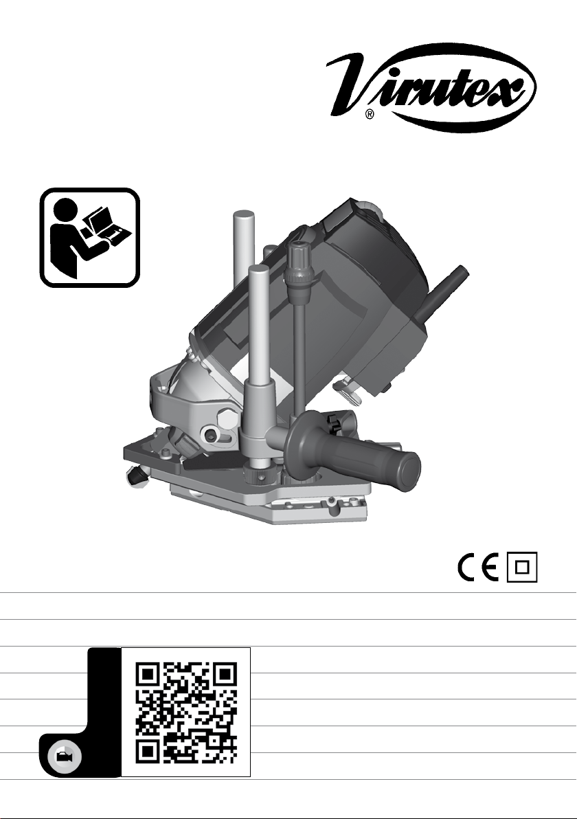
FRE317S
VIDEO DEMO
Fresadora de herrajes
Router for fitting hinges
Fraiseuse paumelleuse
Beschlagfräse
Fresatrice per cerniere
Fresadora de ferragens
Frezarka do materiałów mineralnych
www.virutex.es
Page 2
MANUAL DE INSTRUCCIONES
OPERATING INSTRUCTIONS
MODE D'EMPLOI
GEBRAUCHSANWEISUNG
MANUALE D'ISTRUZIONI
MANUAL DE INSTRUÇÕES
INSTRUKCJA OBSŁUGI
ESPAÑOL Fresadora angular FRE317S
ENGLISH Angle trimmer FRE317S
FRANÇAIS Profileuse d’angle FRE317S
DEUTSCH Winkelfräse FRE317S
ITALIANO Fresatrice angolare FRE317S
PORTUGUÉS Fresadora angular FRE317S
РOLSKI
Frezarka do materiałów mineralnych FRE317S
página/page
seite/pagina
strona
2
9
16
23
31
38
45
ESPAÑOL
FRESADORA ANGULAR FRE317S
(Imágenes en página 54)
Importante
Antes de utilizar la máquina lea atentamente éste MANUAL DE INSTRUCCIONES
y el FOLLETO DE INSTRUCCIONES GENERALES DE SEGURIDAD que se adjunta.
Asegúrese de haberlos comprendido antes
de empezar a operar con la máquina. Conserve los dos manuales de instrucciones
para posibles consultas posteriores.
1. INSTRUCCIONES DE SEGURIDAD PARA EL
MANEJO DE LA FRESADORA
- Asegúrese antes de conectar la máquina, que la tensión
de alimentación, corresponda con la indicada en la chapa
de características.
- Mantenga siempre las manos alejadas del área de
corte y sujete siempre la máquina por las empuñaduras
de la misma.
- Es recomendable trabajar con aspiración de la viruta
para prolongar la vida de la fresa y evitar posible roturas
de la misma.
- Desconecte la máquina de la red eléctrica antes de
realizar cualquier operación de mantenimiento.
2
- Use siempre recambios originales VIRUTEX.
- Utilizar únicamente fresas con el diámetro de la caña
adecuado a la pinza a utilizar y adaptadas a la velocidad
de la fresadora.
- Sostenga la herramienta por las superficies de agarre
aisladas, porque la fresa puede tocar su propio cable
de alimentación. Cortar un cable “en tensión” puede
provocar un choque eléctrico sobre el operario.
- Utilize pinzas u otro medio práctico para fijar y sostener la pieza de trabajo sobre una plataforma estable.
El hecho de sostener la pieza de trabajo con la mano o
contra su cuerpo la hace inestable y puede ocasionar
una pérdida de control.
2. CARACTERÍSTICAS TÉCNICAS
Motor universal............................................................50/60 Hz
Potencia............................................................................1.800W
Velocidad en vacío...................................11.500-23.000/min
Diámetro pinza estándar................................................12 mm
Diámetro máximo de la fresa.........................................61 mm
Profundidad de fresado - Carrera...........................0-100 mm
Galga de profundidad
giratoria....................ajuste de profundidad de 6 posiciones
Peso.....................................................................................5,5 Kg
Nivel de Presión acústica Ponderado A........................91 dBA
Nivel de Potencia acústica Ponderada A...................102 dBA
Incertidumbre de la medición..................................K = 3 dBA
¡Usar protectores auditivos!
Page 3
Nivel total de emisión de vibraciones...............ah: <2,5 m/s
Incertidumbre de la medición.................................K: 1,5 m/s
3. EQUIPO ESTANDAR
En el interior de la caja Ud. encontrará los elementos
siguientes:
- Fresadora angular FRE317S.
- Fresa copetes R. 10 mm d.12 M.D ref. 1740324
- Fresa para ranurar D. 10 mm d. 12 M.D ref. 1140257
- Conjunto escuadra lateral ref. 1745745
- Reductor fresa de 12 a 10 ref. 6022391
- Reductor fresa de 12 a 8 ref. 6022387
- Reductor fresa de 12 a 6 ref. 6022388
- Guía plantilla Ø ext. 30 mm ref. 7722114
- Llave Allen e/c 3 mm
- Llave Allen e/c 5 mm
- Llave fija e/c 13 mm
- Llave fija e/c 24 mm
- Varilla blocaje D. 6 ref. 6027022
- Tapa de aspiración para fresar radios 1723615
- Tubo con conectores de aspiración de 5 m
- Abrazaderas cable-tubo aspiración
- Protector fresa enrasadora ref. 1702744
- Manual de instrucciones y documentación diversa
4. USOS DE LA MÁQUINA
La fresadora angular de alta potencia, 1.800 W, es
apropiada para trabajar materiales minerales como
Corian, Rausolid etc, garantizando buenos resultados.
Su particular diseño permite dos usos bien diferenciados
de la máquina:
Con el motor situado en posición vertical, es una potente
fresadora tupí tradicional, de una gran carrera de trabajo,
ideal para la fabricación y la reparación de elementos
de material mineral.
Emplazando su motor a 45º, le permite trabajar como una
fresadora única para el fresado en radio, de las uniones
de las encimeras con los copetes, incluso en las esquinas
y uniones verticales de dos copetes.
La máquina va provista de toma para aspiración, por la
que puede conectarse, mediante el tubo acoplamiento
aspirador a cualquiera de nuestros aspiradores AS182K,
AS282K, AS382L y ASC482U o a cualquier aspirador
industrial.
5. OPERACIONES COMUNES A LOS DOS USOS
Las operaciones y reglajes comunes, tanto para el fresado
de uniones de copetes, como para utilizar la máquina
como una fresadora tupí, son las siguientes:
5.1. Puesta en marcha y paro de la máquina
La caja del interruptor A, está provista de una palanca B,
que permite el arranque de la máquina y de un seguro de
enclave lateral C (Fig. 1 y 4). Para efectuar el arranque,
2
se acciona el seguro de enclave C, y sin soltarlo, se pulsa
2
la palanca B para que la máquina se ponga en marcha.
Si se pulsa la palanca B de nuevo, el seguro se desenclava automáticamente y la máquina se para. El seguro
de enclave del interruptor impide la puesta en marcha
accidental de la máquina.
Asegúrese siempre que la fresa no está
en contacto con la pieza de trabajo antes
de accionar el interruptor. Una vez la
máquina haya alcanzado su velocidad
máxima, haga contacto con la pieza de
trabajo y pare la máquina una vez la fresa
la haya librado totalmente. De esta manera
aumentará la calidad de su trabajo.
5.2. Regulación de velocidad: 11.500 – 23.000 rpm
El regulador electrónico de velocidad D (Fig. 1) permite
ajustar la velocidad del motor dependiendo del tamaño
del corte y la dureza del material empleado, para lograr un
mejor acabado y aumentar el rendimiento de la máquina.
El control electrónico del par del motor de la FRE317S,
garantiza una velocidad constante incluso bajo carga.
Para aumentar o disminuir la velocidad de la máquina
deberá girar el botón de regulación hacia la derecha
o izquierda en función de la tarea que desee realizar.
Existen 6 números de referencia que facilitan el control
del ajuste de la velocidad deseada.
En la tabla siguiente, se indican las posiciónes del regulador electrónico de velocidad.
Puede consultar también la misma tabla en la propia
máquina.
R.P.M
1
2
3
11.500
13.800
16.100
4
5
max.
Para ajustar la velocidad tenga siempre
en cuenta las recomendaciones del fabricante de la herramienta de corte.
5.3. Giro del cuerpo motor
Para utilizar la FRE317S como una fresadora de radios,
es necesario que la máquina esté situada, con respecto
de la base, con un ángulo de 45° (Fig. 1).
Para utilizarla como una fresadora tupí, es necesario
que la máquina esté en posición vertical 90° (Fig. 2).
Para situar el motor en la posición deseada, basta con
aflojar los tornillos de bloqueo E (Fig. 1 y 2) con la llave
allen de 5, girar el motor hasta que el cabezal F (Fig. 1)
descanse en el tope correspondiente al ángulo deseado
y volver a apretar los tornillos de bloqueo E.
Cuando sea necesario trabajar con una inclinación
18.400
20.700
23.000
3
Page 4
intermedia, se utilizará como guía el indice J2 (Fig. 1),
en la cual se indica el ángulo de inclinación del cuerpo
motor. Una vez situada la máquina en la posición deseada,
apretar firmemente los tornillos de bloqueo E.
5.4. Montaje de las herramientas de corte
Antes de proceder al montaje de la
herramienta de corte asegúrese que la
fresadora esté desconectada de la toma
de corriente de red.
Después de realizar cualquier trabajo,
ponga el interruptor en posición de paro
y antes de dejar la fresadora sobre una
superficie plana, desplace la tuerca y
la contratuerca L (Fig. 4) hasta el tope
superior y suelte la palanca de bloqueo
K (Fig. 4). Por la acción del amortiguador
incorporado, al aflojar dicha palanca el
motor retornará automáticamente a su
posición más elevada.
Para realizar el montaje o la extracción de la herramienta de corte, en primer lugar, asegúrese que está
bloqueado el giro del cuerpo motor por los tornillos de
bloqueo E (Fig. 3).
A continuación presione a fondo el botón de bloqueo
de la fresa G que evita que el eje del motor gire y afloje
la tuerca portapinzas H con la llave de servicio I (Fig. 3).
La pinza y la tuerca portapinzas son dos elementos que
se acoplan a presión entre sí, por lo que debe asegurarse
que la pinza quede asentada perfectamente en la tuerca,
antes de montar ninguna herramienta.
Introduzca la herramienta de corte J (Fig. 3) que se
adecue al trabajo a realizar y si es necesario, el reductor
de fresa correspondiente en el interior de la pinza del
portapinzas H. Apriete firmemente el portapinzas utilizando la llave de servicio, mientras mantiene presionado
el botón de bloqueo G.
Si utiliza una fresa de 12 mm o 1/2” de mango, no necesita
utilizar reductor de fresa. Utilice siempre fresas con la
longitud de corte más corta posible, para minimizar el
riesgo de un descentramiento de la misma.
La fresa, la pinza y el reductor deben estar limpios de
cualquier residuo antes de realizar el montaje.
Evite dejar la máquina sin herramienta
ya que la pinza podría quedar demasiado
apretada y dañar al alojamiento del eje.
Nunca ponga en marcha la máquina
estando el botón de bloqueo de la fresa
presionado.
5.5. Bloqueo de la altura de la máquina
La máquina puede fijarse a cualquier altura de la base,
haciendo girar la palanca de bloqueo K (Fig. 4) en
sentido anti-horario.
Para bloquear la máquina en una posición con absoluta
seguridad, después de fijarla con la palanca de bloqueo
K, (Fig. 4), deberá bloquearla entre las dos tuercas L y M
(Fig. 4), una por encima y la otra por debajo del cuerpo
de la máquina y asegurar dichas tuercas con sus correspondientes contratuercas bloqueándolas firmemente
mediante las dos llaves de servicio N (Fig. 4).
4
5.6. Ajuste de la profundidad
Estando la máquina en el límite superior de su carrera
vertical y la cara de corte frontal de la fresa enrasada con
la superficie de la madera, la profundidad de penetración
puede ajustarse hasta 100 mm.
Para desbloquear la varilla de profundidad O (Fig. 4)
afloje el pomo de fijación de la varilla P. Para ajustar
la profundidad deseada, suba o baje la varilla de profundidad O (Fig. 4) hasta la altura deseada y vuelva a
bloquear la varilla con el pomo de fijación P (Fig. 4).
AJUSTE DE PRECISIÓN. Si desea ajustar o corregir con
precisión la profundidad previamente fijada sólo es necesario girar el pomo de ajuste fino Q (Fig. 4). Una vuelta
completa del pomo corresponde a un desplazamiento
de la varilla de ajuste fino R de 1 mm, teniendo un
recorrido máximo de 5 mm. Cada división del indicador
graduado del ajuste fino S (Fig. 4) corresponde a un
avance de 0.1 mm.
5.7. Conexión de la aspiración
Para conectar la máquina a los aspiradores Virutex
AS182K, AS282K, AS382L ó ASC482U, ó a otra fuente
externa de aspiración, deberá conectar un extremo del
tubo de aspiración incluido en el equipo, en la tobera de
aspiración C2 (Fig. 4) de la máquina y el otro extremo a
la fuente externa de aspiración elegida.
Las abrazaderas E2 (Fig.19) que se montan en el tubo de
aspiración, permiten introducir el cable de alimentación
a través de ellas para facilitar el manejo de la máquina.
6. UTILIZACIÓN COMO FRESADORA DE RADIOS
CÓNCAVOS PARA COPETES
Diseñada para el fresado de radios cóncavos en la unión
de los copetes con las encimeras de material mineral,
está equipada con un guía regulable lateral T (Fig. 1) que
evita dañar el copete y permite realizar el fresado con
facilidad y rapidez, consiguiendo un perfecto acabado.
Para evitar que la fresa pueda causar algún daño en
el material cuando se trabaja, se han incorporado
dos palpadores auxiliares U (Fig. 1) de R10 y R5 para
protegerlo. De esta forma, podrá guiar la máquina de
manera segura siguiendo los topes del palpador y de la
guía regulable (Fig. 5).
Page 5

6.1. Preparación del copete
Para el montaje más correcto del copete es aconsejable
añadir una pieza intermedia entre la encimera y la banda
de copete, para crear una vez fresado un fondo cóncavo
sin junta aparente. La dimensión de la pieza intermedia
dependerá del radio deseado, como se indica en la (Fig.
6). El radio máximo de la fresa en los ejemplos de la (Fig.
6) es de 10 mm y el mínimo de 5 mm.
6.2. Preparación de la fresadora
Desconecte la máquina de la red eléctrica
antes de realizar cualquier operación de
regulación o de ajuste.
Montaje de la herramienta de corte
Para realizar el fresado del radio cóncavo, en primer lugar
montar la fresa de radios, tal y como se ha explicado
en el apartado nº 5.4.
Giro del cuerpo motor (Ver apdo. 5.3)
A continuación aflojar los tornillos de bloqueo E (Fig. 1),
situar el cuerpo motor F en la posición de 45° y volver
a apretar los tornillos firmemente.
Montaje de la tapa de aspiración
Para que la aspiración de las virutas funcione correctamente durante el fresado de radios con la máquina a
45º, es necesario montar la tapa de aspiración B2 (Fig.
1 y 4), debajo de la tobera C2 (Fig. 4) y sujetar ambas
con los mismos tornillos D2 (Fig. 4).
Deberá retirar la tapa de aspiración B2 de la máquina,
cuando quiera utilizarla de nuevo como una fresadora
tupí a 90º.
Ajuste del filo de la herramienta con la base
Ajustar el filo de la fresa J (Fig. 7) hasta que quede perfectamente enrasado con la base de la máquina V (Fig. 7).
Para ello, primero afloje la palanca de bloqueo K (Fig. 4),
desplace el cuerpo de la máquina hasta situar el filo de
la fresa a algunos milímetros de la encimera y vuelva a
bloquear la palanca K en esta posición. Desplace hacia
abajo la tuerca superior L (Fig. 4) de la varilla roscada,
hasta que haga tope con el cuerpo de la máquina. Suelte
de nuevo la palanca de bloqueo K (Fig. 4) y girando la
tuerca superior L (Fig. 4) con la llave de servicio N (Fig.
4), desplace el cuerpo hacia abajo, hasta que el filo de
la fresa quede perfectamente enrasado con la base
de la máquina y bloquee el cuerpo una vez más con
la palanca K (Fig. 4). Suba la tuerca y la contratuerca
M y bloquéelas mediante las dos llaves de servicio N.
Coloque ahora la varilla de ajuste de la profundidad O
(Fig. 4), en su longitud mayor, de modo que su extremo
R (Fig. 4), haga tope en el escalón más bajo de la torre
giratoria de topes W (Fig. 4) y bloquéela con el pomo
de fijación P (Fig. 4).
Ponga ahora el indicador móvil S (Fig. 4) a cero, “0”,
pues ésta será la profundidad de la última pasada final
del fresado del radio.
Ajuste de la guía lateral, con el filo de la herramienta
La máquina incorpora una guía regulable lateral T (Fig.
8) que sirve de guía y apoyo durante el fresado de radios.
Para ajustar la guía regulable lateral, aflojar las dos
tuercas de fijación Y (Fig. 8) y desplazarla girando el
pomo de ajuste fino Z (Fig. 8), hasta que el filo de la fresa
J (Fig. 8) quede enrasado con la guía regulable lateral,
haciendo girar la fresa 360°. Para asegurar la precisión
de esta alineación, utilice un regle de apoyo A1 (Fig. 8).
Una vez determinada la posición correcta de la fresa,
apriete nuevamente las dos tuercas Y (Fig. 8).
Para asegurar un acabado perfecto del radio cóncavo
y de la esquina, antes de proceder al fresado del radio
definitivo, deberá realizar un fresado de desbaste, en
varias pasadas si es necesario, regulando para ello la
guía lateral T (Fig. 8), hacia delante.
6.3. Fresado de la esquina (E3, Figs. 5 y 6)
Se recomienda que el fresado de la esquina en la unión
de los copetes frontal y lateral, se realice antes que el
radio del copete con la encimera.
Deberá desmontar el palpador auxiliar U (Fig. 1), quitando
los tornillos X (Fig. 1), con la ayuda de la llave allen de
3. La máquina deberá estar a 45º con la base, haberse
ajustado el filo de la fresa J a la base del material V (Fig.
7) y la guía regulable lateral T (Fig. 8).
El fresado de la esquina se realizará mediante el descenso
suave y progresivo de la máquina, hasta que la varilla de
profundidad de fresado O (Fig. 4) ajustada anteriormente,
haga tope en el escalón de la torre giratoria de topes W
(Fig. 4). El recorrido máximo de la máquina es de 100 mm.
Antes de realizar el fresado del radio definitivo de la
esquina, se ajustará la guía lateral T (Fig. 8) con el filo de
la herramienta, del modo explicado en el apartaddo 6.2.
6.4. Fresado del radio
Para mejor protección del copete, monte el palpador
auxiliar U (Fig. 1), de radio igual al del copete, mediante
los tornillos X (Fig. 1) y con la ayuda de la llave allen de 3.
Para realizar las pasadas sucesivas de desbaste del material del radio, desplace primero la tuerca L (Fig. 4) hacia
arriba unos milímetros y bloquéela con la contratuerca,
afloje la palanca de bloqueo K (Fig. 4) para que suba
la máquina y mediante el pomo de ajuste fino Q (Fig.
4) desplace la varilla de ajuste fino a la altura deseada
para el primer desbaste, teniendo en cuenta que cada
vuelta entera del pomo Q de “0” a “0”, supone 1 mm de
desplazamiento en altura del tope R (Fig. 4).
Una vez situado el tope a la altura que desea para la
primera pasada de desbaste, presione la máquina hasta
que el tope R (Fig. 4) de la varilla O (Fig. 4), haga tope
con la torre giratoria de topes W (Fig. 4). Bloquee la
máquina con la palanca de bloqueo K (Fig. 4) en esta
posición y realice la primera pasada de fresado de
desbaste del radio.
5
Page 6

Para las sucesivas pasadas de desbaste, deberá colocar
el pomo de ajuste Q (Fig. 4) en la posición que tenga
prevista para cada una de ellas y proceder del mismo
modo que en la anterior.
Para realizar el fresado final del radio, ajuste la guía
lateral T (Fig. 8) con el filo de la herramienta, del modo
explicado en el apartado 6.2, y vuelva a situar la varilla de
profundidad O (Fig. 4) en la posición de inicio previamente
determinada, usando el pomo de ajuste fino Q (Fig. 4).
Desbloquee la palanca K (Fig. 4) y desplace el cuerpo de
la máquina hasta el tope.
Debe asegurarse la fijación de la máquina en esta posición,
para el fresado de la última pasada y para ello deberá
intercalar las dos tuercas y contratuercas L y M (Fig. 4)
firmemente una por encima y otra por debajo del cuerpo
de la máquina, con la ayuda de las dos llaves de servicio
N (Fig. 4), para que quede completamente bloqueada.
En esta posición, la fresa estará perfectamente enrasada
con la base y con el copete y podrá realizar el fresado
del radio definitivo con seguridad.
Antes de proceder al fresado del radio definitivo en la
encimera, realice una prueba previa de fresado, para
comprobar que la altura de la fresa y la posición de la
guía regulable lateral, han sido bien ajustados.
7. UTILIZACIÓN COMO FRESADORA TUPÍ
La máquina se utiliza como fresadora tupí para realizar
reparaciones en la superficie del material mineral y para
otras muchas aplicaciones, como perfilar cantos, fresar
copiando, rebajar o grabar superficies. Como fresadora
tupí constituye un aparato eléctrico enormemente útil.
Su particular diseño permite trabajar cómodamente en
cualquier posición y desde diferentes ángulos.
7.1. Bloqueo de la profundidad de fresado
Para la realización de trabajos repetitivos, en los que la
profundidad de fresado es siempre la misma y donde
conviene evitar la eventualidad de soltar el cabezal por
un accionamiento involuntario de la palanca de bloqueo
K (Fig. 4), puede fijarse el cabezal a la profundidad deseada, entre las dos tuercas L y M (Fig. 4) en cualquier
punto del recorrido.
Cuando trabaje con la profundidad de
fresado bloqueada, la herramienta queda
permanentemente fuera de la superficie
de la base, por lo que deberá:
- Esperar a que la máquina se pare
totalmente antes de dejarla, sobre la
base, en una superficie plana que libre
la herramienta.
- Retirar las tuercas, para volver a las
condiciones normales de bloqueo por la
palanca K en cuanto termine el trabajo.
6
7.2. Realización de cortes profundos
Para realizar con seguridad un corte demasiado profundo
para efectuarlo de una sola pasada, es aconsejable hacer
varios cortes sucesivos utilizando los seis escalones de 3
mm de la torre giratoria de topes W (Fig. 4).
Baje la máquina hasta que la fresa quede nivelada sobre
la superficie donde está apoyada la fresadora. Mediante
la palanca de bloqueo K (Fig. 4) fije la máquina en esta
posición. Afloje el pomo de fijación P (Fig. 4) y baje la
varilla de profundidad O (Fig. 4) hasta que haga tope
con el escalón inferior de la torre giratoria de topes,
utilizando el ajuste fino Q si es necesario. En esta posición,
gire el indicador de profundidad S (Fig. 4) hasta que la
posición cero “0” coincida con la marca de referencia.
Ésta será la posición de inicio que indicará el punto en
el que la fresa entra en contacto con la pieza de trabajo.
Fije la varilla mediante el pomo P, libere la palanca
de bloqueo K (Fig. 4) y deje la máquina en la posición
de reposo. Afloje nuevamente el pomo de fijación P,
desplace la varilla de regulación O (Fig. 4) hacia arriba
hasta la profundidad de corte deseada y nuevamente
bloqueela mediante el pomo P. Gire la torreta W hasta
que el escalón más elevado quede bajo la varilla O (Fig.
4) y realice la primera pasada de corte en la pieza de
trabajo. Gire la torreta hasta el siguiente escalón y realice
otra pasada, y así sucesivamente hasta que alcance la
profundidad final deseada al llegar al escalón inferior.
7.3. Utilización de la guía paralela
La guía paralela (Fig. 9) se utiliza para el perfilado de
bordes y para el corte de ranuras de formas distintas
de acuerdo con las diversas formas de perfiles. Para el
desbarbado de bordes y para una mayor vida de las
fresas son especialmente útiles las fresas de metal duro.
Cuando use la guía paralela, deberá montar la empuñadura Y1 (Fig. 9) en el frontal de la máquina, para trabajar
más comodamente.
Las varillas de la guía paralela se colocan en las aberturas de la base B1 (Fig. 1 y 9) de la parte frontal de
la máquina y se fijan por medio de los dos tornillos C1
(Fig. 9), mediante la llave allen de 5.
AJUSTE NORMAL DE LA ESCUADRA - Aflojar los dos
pomos de fijación D1 (Fig. 9) de la guía, desplazar la
escuadra hasta la medida deseada y volver a apretarlos
en esta posición.
AJUSTE DE PRECISIÓN - Una vez situada la escuadra
E1 y fijada en la posición aproximada se puede efectuar
un ajuste de precisión fino. Para ello, aflojar el pomo de
fijación de la escuadra F1 (Fig. 9), hacer girar el pomo de
ajuste fino G1 hasta la medida deseada y seguidamente
volver a fijar el pomo de fijación F1 de la escuadra en
esta posición. Una vuelta completa del pomo de ajuste
fino corresponde a un desplazamiento de la escuadra de
1 mm, teniendo un recorrido máximo de unos 10 mm.
El indicador graduado de ajuste fino H1 (Fig. 9) puede
moverse independientemente del pomo, lo que permite
Page 7

ajustarlo a cero en cualquier posición mediante la marca
de referencia. Después de ajustar el indicador H1, cuando
gire nuevamente el pomo de ajuste G1, éste girará con
él indicando el desplazamiento que se ha producido en
la escuadra, sabiendo que cada división corresponde a
un avance de 0.1 mm.
7.4. Utilización de las guías plantilla
Las guías plantilla son utilizadas para el fresado de una
gran variedad de formas. Al realizar un copiado aparece
una diferencia de tamaño entre la plantilla y la pieza
fresada. Hay que tener siempre en cuenta la diferencia
entre el radio exterior de la guía plantilla, y el de la
herramienta, al confeccionar la plantilla.
Para poder acoplar la guía plantilla escogida I1 (Fig.
10) a la máquina, se acoplará previamente a una pieza
suplemento J1 (Fig. 10) con los dos tornillos K1 (Fig.
10). El suplemento se sujetará a la base mediante los
dos tornillos y arandelas L1 (Fig. 10).
8. PROTECTOR FRESA ENRASADORA REF. 1740349
Para su seguridad, siempre que utilice la
fresa enrasadora 1740349, o cualquier
fresa para trabajar con el cuerpo motor
situado a 45°, excepto las fresas para
copetes, es imprescindible montar el
protector de la fresa K2 (Fig. 11). Para
ello, una vez enrasada la fresa con la
base, tal y como se ha explicado en el
apartado nº 5.4, coloque el protector y
sujételo firmemente mediante una de las
empuñaduras de la máquina.
9. UTILIZACIÓN DEL EQUIPO PARA CORTES
PARALELOS UF317S. ACCESORIO OPCIONAL
El útil para cortes paralelos ref. 1745838, se compone
de: 2 rieles guía de 650 mm O1 (Fig. 12), 1 juego de
2 conectores Q1 (Fig. 12), un sistema para la guía y
sujeción de la FRE317S M1, N1, (Fig. 12), dos ventosas
y dos sargentos U1 (Fig. 14 y 15), para la sujeción de la
máquina o de los rieles a la pieza y tiene las siguientes
aplicaciones:
- Como útil de cortes paralelos: permite la realización
de cortes paralelos mediante el deslizamiento de la
máquina sobre un riel (Fig. 13).
- Como útil de fijación de la máquina: permite realizar
trabajos que requieran mantener la base de la máquina
bloqueada sobre la pieza. La fijación de la base de la
máquina puede hacerse directamente en el riel o mediante las dos ventosas de apriete que se suministran
con el equipo U1 (Fig. 17), montadas en la base de la
máquina y sobre la pieza.
9.1. Preparación del riel
En primer lugar deberá unir los dos rieles o uno, introduciendo las guías de unión Q1 (Fig. 12) en las ranuras
y bloquear los espárragos R1 (Fig. 12) en los dos rieles,
con la llave allen de 3 mm.
Introduzca ahora el regle guía M1 con la brida de
fijación N1 (Fig. 12), en la cavidad indicada del riel O1
(Fig. 12), por un extremo del mismo y una vez situado
en posición, gire el pomo de apriete P1 (Fig. 12) para
bloquearla al riel.
9.2. Montaje de la máquina en el riel
Sitúe la fresadora junto al riel O1, (Fig. 13), coloque la
brida de apriete N1 sobre los laterales de la base de la
máquina S1 y sujétela firmemente con los dos tornillos
y arandelas de fijación T1, (Fig. 13). La distancia del eje
de la máquina al borde del riel es de 102,5 mm.
9.3. Sujeción del riel a la pieza
CON SARGENTOS: Para la sujeción del riel a la pieza
aconsejamos el empleo de los sargentos de apriete que
se entregan con el accesorio.
Introduzca un sargento en la ranura del riel por cada
extremo del mismo, acérquelos hasta la pieza y sujétela
por sus bordes (Fig. 14).
CON VENTOSAS DE APRIETE: También puede sujetarse
el riel sobre la pieza a trabajar por medio de las ventosas
de apriete, aunque únicamente cuando la superficie de
la pieza sea plana, lisa y sin poros (Fig. 15).
Para montar las ventosas U1 en el riel O1, (Fig. 16), introduzca los tornillos V1 en la ranura dispuesta para tal
fin, coloque la ventosa en los tornillos y sujétela con las
arandelas y palomillas W1 y X1, (Fig. 16). Le aconsejamos
que monte las dos ventosas en el riel, cercanas a cada
borde de la pieza. La ventosa se acciona presionándola
sobre la superficie a la que se va a fijar y llevando la
palanca central a la posición horizontal, como se indica
en la (Fig. 15). Las ventosas han sido estudiadas para la
fijación de las plantillas durante los trabajos de fresado o
serrado. En el caso de trabajos discontinuos, con períodos
prolongados de interrupción, será necesario comprobar
la sujeción de las ventosas, antes de su reanudación.
9.4. Trabajando con el equipo para cortes paralelos
Con la máquina montada en su soporte correspondiente,
sujetaremos el riel a la pieza, sobre la línea de referencia
que habremos trazado previamente, teniendo en cuenta
la distancia entre el centro de la herramienta y el borde
del riel, que ya se ha explicado, y podremos empezar la
operación (Fig. 13).
Se puede utilizar, como referencia del desplazamiento
de la máquina, el regle milimetrado de la guía regulable,
mediante la posición el índice del visor M2 de la brida
de fijación (Fig. 13)
Para utilizar el equipo de cortes paralelos mas comodamente, puede desmontar una de las empuñaduras
7
Page 8

laterales Y1 (Fig. 2) de la fresadora y situarla en la parte
frontal de la máquina Y1 (Fig. 9).
9.5. Fijación de la máquina a la pieza
La fijación de la base de la máquina a la pieza de trabajo,
se puede efectuar colocando las dos ventosas U1 (Fig.
17), incluidas en el equipo para cortes paralelos, en los
laterales de la base de la máquina. Para ello, introduzca
los tornillos y arandelas de fijación de las ventosas T1
(Fig. 17) en los orificios de la base apretando firmemente
y a continuación, accione la palanca de fijación de cada
ventosa en esta posición.
10. REPARACIÓN DE UNA ENCIMERA CON EL
EQUIPO UF317S (Fig. 18)
Con la fresadora FRE317S y el equipo opcional UF317S,
puede recortar fácilmente las partes dañadas de encimeras de material mineral, para su substitución por
elementos nuevos.
10.1 Corte de la encimera
- Monte la herramienta de corte en la máquina, del modo
indicado en el apartado 5.4 de este manual.
- Gire el motor de la máquina a 45°, del modo indicado
en el apartado 5.3 de éste manual.
- Trace sobre la encimera la línea por la que desea cortarla
y trace otra línea paralela a la anterior, a 102,5 mm (+)
ó (-) el radio de la herramienta de corte que va a usar.
Deberá situar el borde del riel del UF317S sobre ésta
segunda línea para cortar la encimera.
- Monte la fresadora FRE317S sobre el equipo UF317S y
fije el riel sobre la línea de referencia con las dos ventosas.
- Regule el tambor giratorio de topes de la fresadora
FRE317S, para cortar la encimera en pasadas sucesivas
de 3 mm de profundidad, tal como se explica en el
apartado 7.2 de éste manual.
- Corte la encimera, llegando hasta el fondo del copete
trasero.
10.2 Corte del copete
- Al terminar el corte de la encimera, y estando la
herramienta en el fondo del copete trasero, fije la
fresadora sobre el riel en ésta posición, apretando el
pomo P1 (Fig. 12).
- Para mayor seguridad, sujete también el otro lado de
la base de la fresadora a la encimera con una ventosa,
del modo explicado en el apartado 9.5 FIJACIÓN DE LA
MÁQUINA A LA PIEZA.
- Corte el copete de abjo a arriba, despacio y con la ayuda
de la fuerza ascendente del amortiguador.
11. MANTENIMIENTO ESCOBILLAS Y COLECTOR
8
Asegúrese que la máquina esté desconectada de la red eléctrica antes de realizar
cualquier manipulación.
Las escobillas deben ser sustituidas cuando tengan
una longitud mínima de 5 mm. Para ello debe quitar
los tapones F2 que sujetan las escobillas G2 (Fig. 20) y
sustituirlas por otras originales de VIRUTEX, asegurándose de que deslicen suavemente en el interior de las
guías. Para desmontar la escobilla situada dentro de la
caja del interruptor, deberá quitar los tornillos H2, (Fig.
20) que sujetan la caja y el interruptor I2, para dejar al
descubierto el tapón F2 (Fig. 20) que la retiene.
Es aconsejable dejar la máquina en marcha en vacío
durante algunos minutos después de un cambio de escobillas. Aproveche el cambio de escobillas para verificar
el estado del colector. Si éste presentase quemaduras o
resaltes es aconsejable llevarlo a reparar a un servicio
técnico VIRUTEX.
12. LUBRICACIÓN Y LIMPIEZA
La máquina se entrega totalmente lubricada de fábrica
no precisando cuidados especiales a lo largo de su vida
útil. Es importante limpiar siempre cuidadosamente la
máquina después de su utilización mediante un chorro
de aire seco. Mantener el cable de alimentación en
perfectas condiciones de uso.
13. ACCESORIOS OPCIONALES
Opcionalmente pueden suministrarse los siguientes
accesorios:
6027103 Pinza Ø 12
6027106 Pinza Ø ½”
6022391 Reductor de 12 a 10
6022387 Reductor de 12 a 8
6022388 Reductor de 12 a 6
6022389 Reductor de 1/2” a 3/8”
6022390 Reductor de 1/2” a 1/4”
1746245 Acoplamiento aspiración de 5 m
6045673 Plantilla para el fresado de elipses y círculos
Gama de fresas para Corian y materiales minerales.
Guías plantillas:
7722168 D. ext. 10 para fresas de D. hasta 6
7722120 D. ext. 12 para fresas de D. hasta 8
7722121 D. ext. 14 para fresas de D. hasta 10
7722122 D. ext. 16 para fresas de D. hasta 12
7722169 D. ext. 18 para fresas de D. hasta 14
7722118 D. ext. 20 para fresas de D. hasta 16
7722119 D. ext. 27 para fresas de D. hasta 23
7722114 D. ext. 30 para fresas de D. hasta 26
1745838 Equipo para cortes paralelos y fijación UF317S
(incluye ventosas y sargentos)
9045754 Riel completo de 1,40 m
9045755 Riel completo de 2,40 m
Page 9

6045756 Ventosa de apriete (juego 2 u.)
6045710 Juego de 2 sargentos de apriete
9045812 Kit unión rieles
6046397 Accesorio escuadra doble
6045669 Accesorio guía de corte circular
6045715 Accesorio guía de corte circular universal UC60
5000000 Plantilla para hacer lazos
6045702 Plantilla para el fresado de encimeras PFE60
6640125 Fresa para herrajes AGB
1745927 Sargento unión ASU317S
1745928 Tirantes unión ATU317S
con sistemas de recogida selectiva de residuos:
La presencia de esta marca en el producto o en el
material informativo que lo acompaña, indica que al
finalizar su vida útil no deberá eliminarse junto con
otros residuos domésticos.
14. NIVEL DE RUIDO Y VIBRACIONES
Los niveles de ruido y vibraciones de esta herramienta
eléctrica han sido medidos de acuerdo con la Norma
Europea EN 60745-2-17 y EN60745-1 y sirven como base
de comparación con máquinas de semejante aplicación.
El nivel de vibraciones indicado ha sido determinado
para las aplicaciones principales de la herramienta,
y puede ser utilizado como valor de partida para la
evaluación de la exposición al riesgo de las vibraciones.
Sin embargo, el nivel de vibraciones puede llegar a ser
muy diferente al valor declarado en otras condiciones
de aplicación, con otros útiles de trabajo o con un
mantenimiento insuficiente de la herramienta eléctrica
y sus útiles, pudiendo llegar a resultar un valor mucho
más elevado debido a su ciclo de trabajo y modo de uso
de la herramienta eléctrica.
Por tanto, es necesario fijar medidas de seguridad de
protección al usuario contra el efecto de las vibraciones,
como pueden ser mantener la herramienta y útiles de
trabajo en perfecto estado y la organización de los
tiempos de los ciclos de trabajo (tales como tiempos
de marcha con la herramienta bajo carga, y tiempos de
marcha de la herramienta en vacío y sin ser utilizada
realmente ya que la reducción de estos últimos puede
disminuir de forma sustancial el valor total de exposición).
15. GARANTÍA
Todas las máquinas electroportátiles VIRUTEX tienen una
garantía válida de 12 meses, a partir del día de suministro,
quedando excluidas todas las manipulaciones o daños
ocasionados por manejo inadecuado o por desgaste
natural de la máquina.
Para cualquier reparación dirigirse al Servicio Oficial de
Asistencia Técnica VIRUTEX.
16. RECICLAJE DE LAS HERRAMIENTAS ELÉCTRICAS
Nunca tire la herramienta eléctrica con el resto de residuos domésticos. Recicle las herramientas, accesorios y
embalajes de forma respetuosa con el medio ambiente.
Respete la normativa vigente de su país.
Aplicable en la Unión Europea y en países europeos
Conforme a la Directiva Europea 2002/96/CE los usuarios
pueden contactar con el establecimiento donde adquirieron el producto, o con las autoridades locales pertinentes,
para informarse sobre cómo y dónde pueden llevarlo
para que sea sometido a un reciclaje ecológico y seguro.
VIRUTEX se reserva el derecho de modificar sus productos
sin previo aviso.
ENGLISH
ANGLE TRIMMER FRE317S
(pictures on page 54)
Important
Prior to using the machine, carefully
read this INSTRUCTION MANUAL and the
attached GENERAL SAFETY INSTRUCTION
LEAFLET. Make sure you understand them
prior to operating the machine. Keep these
manuals for future reference.
1. SAFETY INSTRUCTIONS FOR HANDLING THE
TRIMMER
- Before plugging in the machine, ensure that the
electrical voltage matches that indicated on the characteristics plate.
- Always keep your hands away from the cutting area
and always hold the machine by its handles.
- It is important to work with the chip exhaust to
prolong the life of the trimmer and to prevent any
possible breakages.
- Unplug the machine before performing any maintenance work.
- Always use original VIRUTEX replacement parts.
- Only use bits with a proper shaft diameter for the
clamp to be used and for the speed of the trimmer.
- Hold power tool by insulated gripping surfaces, because
the cutter may contact its own cord. Cutting a “live”
9
Page 10
wire may make exposed metal parts of the power tool
“live” and shock the operator.
-Use clamps or another practical way to secure and
support the workpiece to a stable platform. Holding
the work by your hand or against the body leaves it
unstable and may lead to loss of control.
2. SPECIFICATIONS
Universal motor........................................................50/60 Hz
Input power...................................................................1,800W
No-load speed........................................11,500-23,000/min
Chuck collet Ø................................................................12 mm
Maximum bit diameter...............................................61 mm
Routing depth...........................................................0-100 mm
Revolving depth gauge..........6-position depth adjustment
Weight..................................................................................5.5 Kg
Weighted equivalent continuous
acoustic pressure level A..............................................91 dBA
Acoustic power level A.............................................102 dBA
Uncertainty...............................................................K = 3 dbA
Wear ear protection!
Vibration total values.......................................ah: <2.5 m/s
Uncertainty.........................................................K: 1.5 m/s
3. STANDARD EQUIPMENT
The box contains the following items:
- FRE317S Angle trimmer
- Angle bit R. 10 mm d.12 HM ref. 1740324
- Groove bit D. 10 mm d. 12 HM ref. 1140257
- Lateral fence assembly ref. 1745745
- Reducer 12 to 10 mm ref. 6022391
- Reducer 12 to 8 mm ref. 6022387
- Reducer 12 to 6 mm ref. 6022388
- Template guide Ø ext. 30 mm ref. 7722114
- Allen key 3 mm a/f
- Allen key 5 mm a/f
- Spanner 13 mm a/f
- Spanner 24 mm a/f
- Bar wrench ref. 6027022
- Dust collector cover to trim radius 1723615
- Dust collector pipe with connectors, length 5 m
- Holding brackets for dust collector pipe
- Guard for planer trimmer ref. 1702744
- Operating instructions and other documentation
4. APPLICATIONS OF THE MACHINE
The high power 1,800 W angle trimmer is ideal for
working with mineral materials like Corian, Rausolid,
etc., with good results being guaranteed.
Its special design allows for two different uses of the
machine:
With its motor in an upright position, it is a standard
10
router, with a long working run, ideal for making and
repairing elements made of mineral materials. Placing
the motor at 45º allows it to work as a single trimmer
for angle trimming the rims of worktop joints or even
vertical corners and joints between two rims.
The machine is equipped with a dust collector connection, and the dust collector attachment allows it to be
connected to our AS182K, AS282K, AS382L or ASC482U
or to any other industrial dust collector.
5. OPERATIONS COMMON TO BOTH USES
The following operations and settings are for milling rim
joints, and using the machine as a router:
5.1. Starting and stopping the machine
The switch box A has a trigger, B, which starts the
machine, and a safety button C (Fig. 1 and 4). Start the
machine by pressing the safety button C, and, without
releasing it, squeezing the trigger B to start the machine.
If trigger B is pressed again, the safety switch automatically trips and the machine stops. The safety switch
prevents the machine from starting accidentally.
2
2
Always make sure that the trimmer is not
in contact with the working part before
starting the machine. Once the machine
has reached its maximum speed, make
contact with the working part and only
stop the machine once the bit is fully clear.
This will increase the quality of the work.
5.2. Speed control: 11,500 – 23,000 rpm
The electronic speed control adjusts the speed of the
motor to suit the size of the cut and the hardness of
the material used for a better finish and to increase
machine performance.
The electronic speed control of the FRE317S, ensures
constant speed even when under load. Increase or reduce
the speed of the machine by turning the control button
to the right or left as required. There are 6 reference
numbers to simplify finding the correct speed.
The table below shows the position of the electronic
speed control.
The same table is also on the machine itself.
R.P.M
1
2
3
11,500
13,800
16,100
4
5
max.
Adjust the speed in accordance with, the
recommendations of the cutting tool
manufacturer.
18,400
20,700
23,000
Page 11

5.3. Turning the motor body
When using the FRE317S as a angle trimmer, the machine
must be set at an angle of 45º against its base (Fig. 1).
When using it as a router, the machine must be in an
upright 90º position (Fig. 2).
Set the motor to the desired position by loosening the
lock screws E (Fig. 1 and 2) with the Allen key, turning
the motor until the head F (Fig. 1) is resting on the stop
at the required angle and tightening the lock screws E.
Whenever working at an intermediate angle, use the
scale J2 (Fig. 1) as a guide. This scale indicates the angle
of the motor housing. Once the machine is set at the
correct position, firmly tighten locking screws E.
5.4. Attaching cutting tools
Make sure the trimmer is not connected
to the power supply before attaching the
cutting tool.
Make sure the motor body is blocked by the lock screws
E (Fig. 3) before inserting or removing the cutting tool.
Press the bit lock button G that keeps the motor axle
from turning all the way down and loosen the chuckholder nut H using the spanner I (Fig. 3). The chuck
and the chuck-holder nut fit together under pressure,
so make sure the chuck is perfectly seated in the nut
before inserting any tool.
Insert the cutting tool J (Fig. 3) for the job to be performed
and, if necessary, place the reducer in the chuck-holder
nut H. Firmly tighten the chuck-holder using the spanner, while holding lock button G down. No reducer is
required when using a 12 mm o r ½” shaft bit. Always
use the shortest possible bits to minimize bit decentring.
The bit, the chuck-holder nut and the reducer should
be completely clean before assembly.
After performing any work, place the
switch in the stop position and move the
nut and locking nut L (Fig. 4) to the top
limit and release the locking lever K (Fig.
4) before leaving the trimmer on a flat
surface. The built-in shock absorber will
automatically make the motor return to
its uppermost position when the lever
is released.
5.6. Adjusting the depth
With the machine at the upper limit of its vertical run,
and the front of the cutter bit flush against the wood
surface, the routing depth can be adjusted up to 100
mm. Unlock the depth rod O (Fig. 4) by loosening the
fastening knob P to lower or raise the depth rod O (Fig.
4) and adjust it to the desired depth and once again lock
the rod with the fastening knob P (Fig. 4).
PRECISION ADJUSTMENT. To adjust or correct the
precision of the depth previously set, just turn the fine
adjustment knob Q (Fig. 4). One complete turn of the
knob represents the movement of the fine adjustment
rod of 1 mm, with a maximum run of 5 mm. Each division of the graduated fine adjustment indicator S (Fig.
4) represents a movement of 0.1 mm.
5.7. Connecting the vacuum cleaner
To connect the machine to Virutex AS182K, AS282K,
AS382L or ASC482U vacuum cleaners, or to another
external collection source, one end of the suction tube
included on the appliance should be connected at suction
nozzle C2 (Fig. 4) on the machine and the other end to
the external collection source chosen.
The power cable E2 (Fig. 19) can be fed through the
brackets on the dust collection tube to make the machine
easier to handle.
Do not leave the machine without any tool
as the chuck could become too tight and
damage the shaft housing. Never start
the machine when the bit lock button
is pressed.
5.5. Locking the machine height
The machine can be adjusted to any height from the base
by turning the locking lever K (Fig. 4) counter clockwise.
To lock the machine in a position of full safety, after
fixing it in position with the locking lever K (Fig. 4),
lock it between nuts L and M (Fig. 4), one above and
the other below the body of the machine, and firmly
tighten these nuts with their corresponding locking
nuts, using the two spanners N (Fig. 4).
6. USE AS A CONCAVE RADIAL TRIMMER FOR RIMS
Designed for the trimming of concave radius in the
rim joints of mineral worktops, it is equipped with an
adjustable side guide T (Fig. 1) that prevents damaging
the rim and allows for quick and easy trimming, producing a perfect finish.
The bit is prevented from causing any damage to the
material being worked by incorporating two extra
protective R10 and R5 feelers U (Fig. 1). The machine
can be safely guided using both the stop guide and the
adjustable guide (Fig. 5).
6.1. Preparing the rim
Attach the rim correctly by adding a part between the
worktop and the rim edge to create a concave bottom
with no visible joint after trimming. The size of the
intermediate part will depend on the desired radius as
11
Page 12

shown in (Fig. 6). The maximum trimming radius in the
examples in (Fig. 6) is 10 mm and the minimum is 5 mm.
smoothing trim in several runs if necessary, pushing
lateral guide T (Fig. 8) forward to do this.
6.2. Preparing the Angle Trimmer
Disconnect the machine from the power
supply before making any adjustments.
Fitting the cutting tool
Trim in a concave radius by first attaching the radius
bit, as explained in section 5.4.
Turning the motor body (See section 5.3)
Then loosen lock screws E (Fig. 1), set motor body F to
45° and firmly retighten the screws.
Fitting the vacuum cleaner cover
For chips to be collected properly during the trimming of
radius with the machine at 45º, mount the dust collector
cover B2 (Fig. 1 and 4) below the nozzle C2 (Fig. 4) and
fasten both with screws D2 (Fig. 4). Remove the dust
collector cover B2 from the machine when it is to be
again used as a router at 90º.
Matching the edge of the tool to the base
Adjust the edge of the bit J (Fig. 7) until it is perfectly
flush with the base of the machine V (Fig. 7). Then
loosen the locking lever K (Fig. 4), move the machine
body until the bit edge is a few millimetres away from
the worktop and lock the bar K in that position. Move
the upper nut L (Fig. 4) down the threaded rod until
it reaches the machine body. Loosen the locking lever
again K (Fig. 4) and turn the upper nut L (Fig. 4) with
the spanner N (Fig. 4), move the body downwards until
the edge of the bit is fully flush with the base of the
machine and lock the body again with the lever K (Fig.
4). Move the nut and locking nut M upwards and lock
them using the two spanners N. Now place the depth
adjustment rod O (Fig. 4) at its maximum length so
that its end R (Fig. 4) presses against the lowest step
of the revolving stop turret W (Fig. 4) and lock it with
the fastening knob P (Fig. 4). Now place the movable
indicator S (Fig. 4) at zero, 0, as this will be the depth
of the final run of the radial trim.
Matching the adjustable lateral fence with the edge
of the tool.
The machine has an adjustable lateral guide T (Fig. 8) that
guides and supports it while trimming radius.
Adjust the lateral guide by loosening the two fastening screws Y (Fig. 8) and move it by turning the fine
adjustment knob Z (Fig. 8) until the edge of the bit J
(Fig. 8) is flush with the adjustable lateral guide, turn
the bit 360°. Ensure the precision of this alignment by
using a support ruler A1 (Fig. 8). After determining the
correct position of the bit, once again tighten the two
nuts Y (Fig. 8).
Ensure a perfect finish of the concave radius and the
corner before the final radial trim by first making a
12
6.3. Corner trimming (E3, Figs. 5 and 6)
It is recommendable that the corner of the joint between
front and side rims be trimmed before the radius of the
rim with the worktop. Perform corner trimming of the
joint between the worktop and the rim by detaching
the extra feeler U (Fig. 1). Remove the screws X (Fig. 1),
with the aid of a no. 3 allen key.
The machine must be in a 45º position against the base,
with the edge of the bit J adjusted to the base of the material V (Fig. 7) and the adjustable lateral guide T (Fig. 8).
Trim the corner with a smooth and gradual descent of
the machine until the previously adjusted trimming
depth rod O (Fig. 4), presses against the step of the
revolving stop turret W (Fig. 4). The maximum run of
the machine is 100 mm.
Before the final corner trimming, lateral guide T (Fig.
8) should be adjusted with the edge of the tool, as
explained in section 6.2.
6.4. Corner-rounding
For better corner protection, fit extra feeler U (Fig. 1),
with the same radius as the rim, using screws X (Fig. 1)
and with the aid of a no. 3 Allen key.
Make successive smoothing runs of the radial material
by first moving nut L (Fig. 4) upwards a few millimetres
and tightening it with the locking nut, loosen locking
lever K (Fig. 4) so that the machine can be raised and
use the fine adjustment knob Q (Fig. 4) to move the fine
adjustment rod to the height of the first smoothing run.
Bear in mind that each full turn of the knob Q from
“0” to “0” represents 1 mm of movement in height of
the stop R (Fig. 4).
With the stop at the required height for the first
smoothing run, move the machine until the stop R (Fig.
4) of the rod O (Fig. 4), presses against the revolving stop
turret W (Fig. 4). Lock the machine in this position with
the locking lever K (Fig. 4) and make the first smoothing
run of the trim radius.
For successive smoothing runs, place the adjustment
knob Q (Fig. 4) in the position for each one and proceed
as described above.
To make the final radial trim, adjust lateral guide T (Fig. 8)
with the edge of the tool, as explained in section 6.2, and
place the depth rod O (Fig. 4) back in the previously determined position by using the fine adjustment knob Q (Fig. 4).
Unlock the bar K (Fig. 4) and move the body of the
machine to the stop. Make sure the machine is secure
in this position for the last trim run by tightening the
two nuts and lock nuts L and M (Fig. 4), one firmly above
and the other below the machine body with the aid of
the two spanners N (Fig. 4).
In this position, the bit will be flush with the base and
the rim and the final radial trim can be performed safely.
Page 13

Before final trimming of the radius on the worktop,
make a test run to check that the height of the bit and
the position of the adjustable lateral guide have been
adjusted correctly.
7. USE AS A SURFACE ROUTER
The machine can be used as a surface router to repair
the surface of mineral material and for many other
applications such as profiling edges, copy milling, lowering or engraving surfaces. As a surface router it is an
extremely useful machine as its design allows working
in any position and from different angles.
7.1. Locking the trimming depth
For repetitive work, where the depth of the trim is always
the same and where it is useful to avoid releasing the
head through involuntary movement of the locking lever
K (Fig. 4), the head can be fixed at the desired depth by
placing the two lock nuts L and M (Fig. 4) on the shaft,
threading one above and one below the head and thus
it to be blocked at any point along the depth setting.
When working with the trimming depth
blocked, the tool is permanently off the
surface of the base. This requires the
following actions:
- Wait for the machine to come to a complete stop before placing it on its base on
a flat surface in such a way that the tool
does not come into contact with the surface.
- Remove the nuts to return to normal
locking conditions using the lever K as
soon as the work is completed.
7.2. Making deep cuts
When performing cuts that are too deep to carry out
with in a single run, we recommend making several
successive runs using the six 3-mm steps on the revolving
depth turret W (Fig. 4).
Lower the machine until the cutting bit is level with the
surface on which the trimmer is resting. Use the locking
knob K (Fig. 4) to set the machine in this position. Loosen
fastening knob P (Fig. 4) and lower the depth rod O (Fig.
4) until it presses against the lower step of the revolving
depth turret using fine adjustment knob Q if necessary.
In this position, turn the depth indicator S (Fig. 4) until
the zero position matches the reference mark. This will
be the starting position indicating the point at which
the bit comes into contact with the material.
Hold the rod in place with knob K (Fig. 4), release locking knob E and leave the machine in the off position.
Loosen fastening knob P, move the adjustment rod O
(Fig. 4) upwards to the desired cutting depth and lock
it again with knob P. Turn turret W until the highest
step is below the rod O (Fig. 4) and make the first cut
in the material. Turn the turret to the next step and
make another run, and so on until the required depth
is attained when the lowest step is reached.
7.3. Using the parallel guide
The parallel guide (Fig. 9) is used for trimming edges and
cutting slots of different shapes to match different profiles.
Hard metal cutting bits are particularly useful for smoothing
edges and lengthening the working life of the bits.
When you use the parallel guide, you will have to fit
handle Y1 (Fig. 9) on the front of the machine to work
more comfortably.
Parallel guide rods are placed in the base openings B1
(Fig. 1 and 9) on the front of the machine and fastened
with two screws C1 (Fig. 9) using a number 5 allen key.
NORMAL SQUARE ADJUSTMENT - Loosen the two
fastening knobs D1 (Fig. 9) of the guide, move the
square to the required measurement and fasten it in this.
PRECISE ADJUSTMENT - Once the square E1 has been
approximately positioned and held in place, a further
fine adjustment may be made. Loosen square fastening
knob F1 (Fig. 9) and turn the fine adjustment knob G1
to the required measurement before tightening the
square fastening knob F1 in this position. One full turn
of the knob moves the square by 1 mm, with a maximum distance of 10 mm. The gauged fine-adjustment
indicator H1 (Fig. 9) can be moved separately from the
knob, so that it may be set to 0 from any position using
the reference mark. After adjusting the indicator H1
when turning the adjustment knob G1, it will indicate
the degree to which the square has moved, each division
representing an advance of 0.1 mm.
7.4. Using templates
Templates are used for surface routing in a wide variety
of ways. When making a copy, there is a difference in size
between the template and the routed part. The difference
between the external radius of the template and the
cutting tool must always be taken into consideration
when making a template.
Fit the chosen template I1 (Fig. 10) to the machine by
first fitting an extra part J1 (Fig. 10) with two screws
K1 (Fig. 10). Fasten this accessory to the base with two
screws and washers L1 (Fig. 10).
8. GUARD FOR PLANER TRIMMER REF. 1740349
For your safety, whenever using planer
trimmer 1740349 or any trimmer with
the motor housing at a 45° angle, except
corner trimmers, always fit trimmer guard
K2 (Fig. 11). Once the trimmer is level with
the base, as described in section 5.4, place
the guard in position and hold it firmly
using one of the handgrips on the machine.
13
Page 14

9. UF317S USING THE MACHINE FOR PARALLEL
CUTS. OPTIONAL ACCESSORY
Parallel cutting tool ref. 1745838 is made up of: 2 O1
650 mm guide rails (Fig. 12), 1 set of 2 Q1 connectors
(Fig. 12), a system for guiding and fastening FRE317S
M1, N1, (Fig. 12), two suction pads and two U1 G-clamps
(Fig. 14 and 15) to fasten the machine or the rails to
the part, and with the following uses:
- As a tool for parallel cuts. Parallel cuts can be made
by sliding the machine along a rail (Fig. 13).
- As a tool for fastening the machine: it can perform
work that requires maintaining the base of the machine
locked on a part. The base of the machine can be fastened
directly to the fastening unit or by using the suction
cups provided with the unit U1 (Fig. 17). The base of
the machine can be directly fastened at the rail or by
using the two suction pads supplied with equipment
U1 (Fig. 17), and which are fitted on the machine base
and the part.
9.1. Preparing the rail
First, join the two rails by inserting the joint guides Q1
(Fig. 12) in the slots and locking the studs R1 (Fig. 12)
on the two rails using the 3 mm allen key.
Now insert the guide rule M1 with the fixing clamp N1
(Fig. 12), through one end of the slot in rail O1 (Fig. 12)
and, once in position, tighten the knob P1 (Fig. 12) to
lock it to the rail.
9.2. Attaching the machine to the rail
Place the trimmer beside rail O1, (Fig. 13), attach the
fixing clamp N1 to the sides of the machine base S1
and fasten it firmly with the two screws T1 (Fig. 13).
The distance between the machine shaft and the edge
of the rail is 102.5 mm.
If work is carried out non-continuously, with long breaks
in between, the suction of the cups should be checked
before resuming work.
9.4. Working with the machine for parallel cuts
With the machine mounted on its support, fasten the
rail to the material along a previously traced reference
line. Make sure the distance between the centre of the
tool and the edge of the rail is correct as explained
above and begin work (Fig. 13).
As a reference for moving the machine, you can use
the millimetre ruler on the adjustable guide through
the position of the pointer of sight M2 on the fixing
clamp (Fig. 13)
Use the parallel cutting machine more comfortably by
removing one of the side handles Y1 (Fig. 2) from the
trimmer and placing it on the front of the machine
Y1 (Fig. 9).
9.5. Fastening the machine to the material
It is possible to fix the machine to the material to be
trimmed To do this fasten the base of the machine to
the material by placing the two suction cups U1 (Fig.
17) included with the parallel cutting accessory to the
sides of the base of the machine. Insert the suction cup
fixing screws T1 (Fig. 17) in the holes in the base pressing
firmly and turn the fastening lever on each suction cup
to fix it in position.
10. REPAIRING A WORK TOP WITH THE EQUIPMENT UF317S (Fig. 18)
With the FRE317S angle trimmer and optional equipment UF317S you can easily cut out damaged work
top parts made of mineral materials, replacing them
with new parts.
9.3. Fastening the rail to the part
USING G-CLAMPS: Fasten the rail to the part using
the g-clamps provided with the accessory.
Insert one g-clamp in the slot of the rail at each end, bring
it close to the part and fasten it to the edges (Fig. 14).
USING SUCTION CUPS: The rail can also be fastened
to a part to be worked on with suction cups. This is only
possible when the surface of the material is flat, smooth
and pore-free (Fig. 15).
Mount the suction cups U1 on rail O1, (Fig. 16) by inserting
two screws V1 in the slot. Place the cup on the screws
and fasten it with the washers and wing nuts W1 and
X1, (Fig. 16). We recommend attaching the suction cups
to the rail near each edge of the material. The cup acts
by pressing it down on the surface to which it will be
fastened and moving the central lever to a horizontal
position, as shown in (Fig. 15). The suction cups have
been designed for holding templates during trimming
or sawing work.
14
10.1 Cutting the Work Top
- Attach the cutting tool to the machine, as indicated
in section 5.4 of this manual.
- Turn the motor 45°, as indicated in section 5.3 of
this manual.
- Trace one line on the work top where you want to
cut and another one parallel to it, 102.5 mm (+) or (-)
the radius of the cutting tool you are going to use. The
edge of the UF317S rail must be placed over this second
line to cut the work top.
- Fit angle trimmer FRE317S on equipment UF317S and
fix the rail to the reference line with the two suction pads.
- Adjust the revolving stopper drum on angle trimmer
FRE317S to cut the work top in successive 3 mm deep
cuts, as explained in section 7.2 of this manual.
- Cut the work top, reaching the bottom of back rims.
10.2 Cutting rims
- When you have finished cutting the work top, set the
Page 15

angle trimmer on the rail in this position by tightening
knob P1 (Fig. 12) and with the tool at the bottom of
the back rim.
- For greater safety, you should also use a suction pad
to fasten the other side of the angle trimmer base to
the work top, as explained in section 9.5 FASTENING
THE MACHINE TO THE PART.
- Slowly cut the rim in an upwards direction with the
assistance of the rising force of the shock absorber.
11. MAINTAINING THE BRUSHES
AND COLLECTOR
Make sure the machine is disconnected
from the power supply before performing
any maintenance work.
The brushes must be replaced when they have a minimum
length of 5 mm. Remove the covers F2 that hold the
brushes G2 (Fig. 20) and replace them with VIRUTEX
originals, making sure they slide smoothly inside the
guides. Remove the brush inside the switch box by
loosening the screws H2 (Fig. 20) that hold the box and
the switch I2 in position to reveal the cover F2 (Fig. 20).
Allow the machine to operate without load for a few
minutes after changing the brushes. Take advantage of
the brush change to check the condition of the collector.
If it appears burnt or has burrs it should be repaired by
the VIRUTEX repair service.
12. LUBRICATION AND CLEANING
The machine is factory delivered fully lubricated and
needs no special care throughout its working life. It is
important to carefully clean the machine after use with
a jet of dry air. Keep the power cable in good condition.
13. OPTIONAL ACCESSORIES
The following accessories are optional:
6027103 Chuck collet Ø 12
6027106 Chuck collet Ø ½”
6022391 Reducer 12 to 10
6022387 Reducer 12 to 8
6022388 Reducer 12 to 6
6022389 Reducer 1/2” to 3/8”
6022390 Reducer 1/2” to 1/4”
1746245 Dust collector tube, length 5 m
6045673 Template for trimming ellipses and circles
Range of bits for corian and solid surface materials.
Guide rings:
7722168 D. ext. 10 for bits Ø up to 6
7722120 D. ext. 12 for bits Ø up to 8
7722121 D. ext. 14 for bits Ø up to 10
7722122 D. ext. 16 for bits Ø up to 12
7722169 D. ext. 18 for bits Ø up to 14
7722118 D. ext. 20 for bits Ø up to 16
7722119 D. ext. 27 for bits Ø up to 23
7722114 D. ext. 30 for bits Ø up to 26
1745838 UF317S Cutting guide with suction cups and
clamps.
9045754 Complete rail, length 1.40 m
9045755 Complete rail, length 2.40 m
6045756 Suction cup (set of 2)
6045710 Set of 2 clamps
9045812 Jointing kit for cutting guide
6046397 Dual square accessory
6045669 Guide accessory for circular cutting
6045715 UC60 Universal guide accessory for circular
cutting
5000000 PL11 Dovetail attachment
6045702 PFE60 Template for trimming work tops
6640125 Bit for AGB fittings
1745927 ASU317S Joining clamp
1745928 ATU317S Joining straps
14. NOISE AND VIBRATION LEVEL
The noise and vibration levels of this device have been
measured in accordance with European standard EN
60745-2-17 and EN 60745-1 and serve as a basis for comparison with other machines with similar applications.
The indicated vibration level has been determined for
the device’s main applications and may be used as an
initial value for evaluating the risk presented by exposure to vibrations. However, vibrations may reach levels
that are quite different from the declared value under
other application conditions, with other tools or with
insufficient maintenance of the electrical device or its
accessories, reaching a much higher value as a result
of the work cycle or the manner in which the electrical
device is used.
Therefore, it is necessary to establish safety measures
to protect the user from the effects of vibrations, such
as maintaining both the device and its tools in perfect
condition and organising the duration of work cycles
(such as operating times when the machine is subjected
to loads, and operating times when working with no-load,
in effect, not in use, as reducing the latter may have a
considerable effect upon the overall exposure value).
15. WARRANTY
All VIRUTEX power tools are guaranteed for 12 months
from the date of purchase, exlcuding any domage which
is a result of incorrect use or of natural wear and tear
on the machine. All repairs should be carried out by the
official VIRUTEX technical assistance service.
16. RECYCLING ELECTRICAL EQUIPMENT
Never dispose of electrical equipment with domestic was-
15
Page 16
te. Recycle equipment, accessories and packaging in ways
that minimise any adverse effect on the environment.
Comply with the current regulations in your country.
Applicable in the European Union and in European
countries with selective waste collection systems:
If this symbol appears on the product or in the accompanying information, at the end of the product’s useful
life it must not be disposed of with other domestic waste.
In accordance with European Directive 2002/96/EC, users
may contact the establishment where they purchased the
product or the relevant local authority to find out where
and how they can take the product for environmentally
friendly and safe recycling.
VIRUTEX reserves the right to modify its products
without prior notice.
FRANÇAIS
PROFILEUSE D’ANGLE FRE317S
(Images page 54)
Important
Avant d’utiliser la machine, lire attentivement ce MODE D’EMPLOI et la
BROCHURE D’INSTRUCTIONS GÉNÉRALES
DE SÉCURITÉ, ci-jointe. S’assurer de bien
avoir compris ces instructions avant de
commencer à travailler avec la machine.
Conserver les deux modes d’emploi pour
de futures consultations.
1. INSTRUCTIONS DE SÉCURITÉ POUR LE
MANIEMENT DE LA PROFILEUSE
- Vérifier avant de brancher la machine que la tension
d’alimentation correspond à celle indiquée sur la plaque
des caractéristiques.
- Toujours maintenir les mains éloignées de la zone de
coupe et toujours tenir la machine par ses poignées.
- Il est recommandé de travailler avec un aspirateur de
copeaux pour prolonger la durée de vie de la fraise et
éviter qu’elle se casse.
- Débrancher la machine du secteur avant toute opération d’entretien.
16
- Toujours utiliser des pièces de rechange d’origine
VIRUTEX.
- N’utiliser que des fraises au diamètre de tige correct,
adaptées à la pince utilisée et à la vitesse de l’outil.
- Tenir l’outil électrique par les surfaces de préhension
isolantes, car la fraise peut être en contact avec son
proper câble. Le fait de couper un fil “sous tension” peut
ëgalement mettre “sous tension” les parties métalliques
exposées de l’outil électrique et provoquer un choc
électrique sur l’opérateur.
- Utiliser des pinces ou tout autre moyen pratique pour
fixer et supporter la pièce à travailler sur une plateforme
estable. La tenue de la piéce à travailler à la main ou
contre le corps la rend instable et peut conduire à une
perte de contrôle de l’outil.
2. CARACTÉRISTIQUES TECHNIQUES
Moteur universel...............................................50/60 Hz
Puissance..............................................1.800 W
Vitesse à vide...........................11.500-23.000/min
Diamètre pince standard.............................................12 mm
Diamètre max. de la fraise....................................61 mm
Profondeur de défonçage....................................0 - 100 mm
Calibre de profondeur rotatif...........réglage à 6 positions
Poids......................................................................................5,5 kg
Niveau de pression acoustique
continu équivalent pondéré A..................................91 dBA
Niveau de puissance acoustique A........................102 dBA
Incertitude.................................................................K = 3 dbA
Porter une protection acoustique!
Valeurs totales des vibrations..........................ah: <2,5 m/s
Incertitude..............................................................K: 1,5 m/s
3. ÉQUIPEMENT STANDARD
La mallette contient les éléments suivants:
- Profileuse d’angle FRE317S
- Fraise d’angles R. 10 mm d. 12 M.D. réf. 1740324
- Fraise à rainurer D. 10 mm d. 12 M.D. réf. 1140257
- Ensemble équerre latérale réf. 1745745
- Réducteur de 12 à 10 réf. 6022391
- Réducteur de 12 à 8 réf. 6022387
- Réducteur de 12 à 6 réf. 6022388
- Douille de guidage Ø ext. 30 mm réf. 7722114
- Clé six pans o/c 3 mm
- Clé six pans o/c 5 mm
- Clé plate o/c 13 mm
- Clé plate o/c 24 mm
- Clef à barre réf. 6027022
- Couvercle d’aspiration pour le profilage de rayons
1723615
- Flexible d’aspiration de 5 m
2
2
Page 17
- Colliers câble – tuyau d’aspiration
- Protecteur de fraise de profilage, réf. 1702744
- Mode d’emploi et documentation diverse
4. UTILISATION DE LA MACHINE
Équipée d’un puissant moteur de 1.800 W, la profileuse
d’angle est conçue pour travailler sur des matériaux
minéraux tels que le Corian, le Rausolid, etc., en garantissant de bons résultats.
La conception particulière de cette machine permet
deux utilisations bien différenciées:
Avec le moteur en position verticale, c’est une puissante
défonceuse traditionnelle, ayant une grande course
de travail, idéale pour la fabrication et la réparation
d’éléments en matériau minéral. En situant son moteur
à 45º, elle peut travailler comme une profileuse pour le
profilage en rayon des assemblages des plans de travail,
y compris dans les coins et les assemblages verticaux
à deux onglets.
La machine est pourvue d’une prise d’aspiration,
permettant de la brancher, à l’aide du tuyau du kit
aspiration standard, sur l’un de nos aspirateurs AS182K,
AS282K, AS382L et ASC482U ou sur tout autre aspirateur industriel.
5. OPÉRATIONS COMMUNES
AUX DEUX UTILISATIONS
Les opérations et les réglages communs au profilage
d’assemblages et à l’emploi de la machine comme
défonceuse sont les suivants:
5.1. Mise en marche et arrêt de la machine
Le boîtier de l’interrupteur A est pourvu d’un levier B
qui permet de mettre en marche la machine et d’un
verrouillage de sécurité latéral C (Fig. 1 et 4). Pour le
démarrage, il faut débloquer le verrouillage de sécurité
C et, sans le lâcher, appuyer sur le levier B pour que la
machine se mette en marche.
Si on appuie de nouveau sur le levier B, le verrouillage
de sécurité se débloque automatiquement et la machine
s’arrête. Le verrouillage de sécurité de l’interrupteur
empêche la mise en marche accidentelle de la machine.
Toujours s’assurer que la fraise n’est pas
en contact avec la pièce à travailler avant
d’actionner l’interrupteur.
Ne mettre l’appareil en contact avec la
pièce à travailler qu’une fois la vitesse
maximale est atteinte, et n’arrêter la
machine que lorsque la fraise est totalement sortie de la pièce. Ceci permet
d’améliorer la qualité du travail.
5.2. Réglage de la vitesse: 11500-23000 t/min
Le variateur électronique de vitesse D (Fig. 1) permet de
régler la vitesse du moteur en fonction de la dimension
de coupe et de la dureté du matériau employé, pour
une meilleure finition et pour améliorer le rendement
de la machine.
Le contrôle électronique du couple moteur de FRE317S
assure une vitesse constante même en charge. Pour
augmenter ou réduire la vitesse de la machine, il faut
tourner le bouton de réglage vers la droite ou vers
la gauche en fonction de la tâche à réaliser. Il existe
6 positions de référence qui facilitent le contrôle du
réglage de la vitesse voulue.
Le tableau suivant indique la position du variateur
électronique de vitesse.
Ce même tableau peut également être consulté sur la
machine, elle-même.
R.P.M
1
2
3
11.500
13.800
16.100
4
5
max.
18.400
20.700
23.000
Pour régler la vitesse, il faut toujours tenir
compte des recommandations du fabricant
de l'outil de coupe.
5.3. Rotation du bloc moteur
Pour employer la FRE317S comme profileuse d’angle, il
faut que la machine soit située à un angle de 45º (Fig.
1) par rapport à la base.
Pour l’employer comme défonceuse, il faut mettre la
machine en position verticale à 90º (Fig. 2).
Pour situer le moteur dans la position voulue, il suffit de
dévisser les vis de blocage E (Fig. 1 et 2) avec la clé six
pans de 5, de faire tourner le moteur jusqu’à ce que la
tête F (Fig. 1) repose sur la butée correspondant à l’angle
voulu et de revisser les vis de blocage E.
Pour travailler avec une inclinaison intermédiaire, utiliser comme guidage l’index J2 (Fig. 1), sur lequel est
indiqué l’angle d’inclinaison du bloc moteur. Une fois
la machine située dans la position voulue, bien serrer
les vis de blocage E.
5.4. Montage des outils de coupe
Avant de monter l'outil de coupe, il faut
s'assurer que la machine est débranchée
du secteur.
Pour monter ou retirer l’outil de coupe, il faut tout
d’abord s’assurer que la rotation du bloc moteur est
bloquée par les vis de blocage E (Fig. 3).
17
Page 18

Ensuite, il faut appuyer à fond sur le bouton de blocage
de la fraise G qui évite que l’arbre moteur tourne, puis
dévisser l’écrou porte-pinces H avec la clé de service I
(Fig. 3). La pince et l’écrou porte-pinces sont assemblés
entre eux à pression, c’est pourquoi il faut s’assurer que
la pince est parfaitement assise dans l’écrou, avant de
monter un outil.
Introduire l’outil de coupe J (Fig. 3) adapté au travail à
réaliser et, si necessaire, le réducteur correspondant à
l’intérieur de la pince du porte-pinces H. Serrer fermement le porte-pinces en utilisant la clé de service, tout
en appuyant sur le bouton de blocage G. Si on utilise
une fraise de à queue 12 mm ou de 1/2”, il n’est pas
nécessaire d’utiliser un réducteur. Toujours utiliser des
fraises ayant une longueur de coupe la plus petite possible, pour réduire le risque d’un décentrage de celle-ci.
La fraise, la pince et le réducteur doivent être correctement nettoyés avant de faire le montage.
Éviter de laisser la machine sans outil car
la pince pourrait rester trop serrée, ce
qui endommagerait le logement de l'axe.
Ne jamais mettre en marche la machine
quand le bouton de blocage de la fraise
est enfoncé.
5.5. Blocage de la hauteur de la machine
On peut fixer la machine sur n’importe quelle hauteur
par rapport à la base, en tournant le levier de blocage K
(Fig. 4) dans le sens inverse des aiguilles d’une montre.
Pour bloquer en toute sécurité la machine dans une
position, après l’avoir fixée avec le levier de blocage
K (Fig. 4), il faut la bloquer entre les deux écrous L et
M (Fig. 4), l’un au-dessus et l’autre au-dessous du bloc
machine et serrer ces écrous avec leurs contre-écrous
en les bloquant fermement avec les deux clés de service
N (Fig. 4).
À la fin de tout travail, mettre l’interrupteur
en position d’arrêt et avant de laisser la
profileuse sur une surface plane, déplacer
l'écrou et le contre-écrou L (Fig. 4) jusqu’à
sa butée supérieure, puis desserrer le levier
de blocage K (Fig. 4). En desserrant ce levier,
l’amortisseur incorporé permet au moteur
de revenir automatiquement à sa position
la plus élevée.
de la tige P. Pour régler la profondeur voulue, monter
ou descendre la tige de profondeur O (Fig. 4) jusqu’à la
hauteur voulue et bloquer de nouveau la tige avec le
bouton de fixation P (Fig. 4).
RÉGLAGE DE PRÉCISION. Pour régler ou corriger avec
précision la profondeur préalablement fixée, il suffit
de tourner le bouton de réglage fin Q (Fig. 4). Un tour
complet du bouton correspond à un déplacement de la
tige de réglage fin R de 1 mm, la course maximale de
cette tige étant de 5 mm. Chaque division de l’indicateur
gradué du réglage fin S (Fig. 4) correspond à un incrément de 0,1 mm.
5.7. Branchement du système d’aspiration
Pour connecter la machine aux aspirateurs Virutex
AS182K, AS282K, AS382L ou ASC482U, ou à d’autres
sources externes d’aspiration, vous devrez connecter
une extrémité du tube d’aspiration que vous trouverez
dans l’équipement, à la tuyère d’aspiration C2 (Fig. 4)
de la machine et l’autre extrémité à la source externe
d’aspiration choisie.
Les colliers E2 (Fig. 19) à monter sur le tuyau d’aspiration
permettent d’y introduire le câble d’alimentation pour
faciliter le maniement de la machine.
6. UTILISATION COMME PROFILEUSE
D’ANGLE À RAYONS CONCAVES
Conçue pour le profilage en rayons concaves des assemblages des plans de travail en matériau minéral, la
machine est équipée d’un guidage latéral réglable T (Fig.
1) qui évite d’endommager l’angle et permet de réaliser
aisément et rapidement le profilage en obtenant une
excellente finition.
Pour éviter tout dommage causé par la fraise sur le
matériau à travailler, la machine incorpore deux palpeurs
auxiliaires U (Fig. 1) de R10 et R5 pour le protéger. Ceci
permet de guider la machine en toute sécurité en suivant
les butées du palpeur et du guidage réglable (Fig. 5).
6.1. Préparation de l’angle
Pour un montage plus correct de l’angle, il est conseillé
d’ajouter une pièce intermédiaire entre le plan de travail
et la bande d’angle, pour créer après le profilage un
fond concave sans joint apparent. La dimension de la
pièce intermédiaire dépendra du rayon voulu, comme
cela est indiqué sur la (Fig. 6). Le rayon maximum de la
fraise sur les exemples de la (Fig. 6) est de 10 mm et le
rayon minimum de 5 mm.
5.6. Réglage de la profondeur
Quand la machine se trouve sur la limite supérieure de sa
course verticale et la face de coupe frontale de la fraise
à ras de la surface du bois, la profondeur de pénétration
peut être réglée jusqu’à 100 mm. Pour débloquer la tige
de profondeur O (Fig. 4), dévisser le bouton de fixation
18
6.2. Préparation de la profileuse
Débrancher la machine du secteur, avant
toute opération de réglage.
Page 19

Montage de l’outil de découpe
Pour faire le profilage du rayon concave, il faut tout
d’abord monter la fraise d’angle, comme cela est expliqué
au paragraphe 5.4.
Rotation du corps moteur (Voir paragraphe 5.3)
Desserrer légèrement les vis de blocage E (Fig. 1), placer le
corps moteur F en position 45° et resserrer les vis à fond.
Montage du couvercle d’aspiration
Pour que l’aspiration des copeaux fonctionne correctement pendant le profilage de rayons avec la machine à
45º, il faut monter le couvercle d’aspiration B2 (Fig. 4),
sous la buse C2 (Fig. 4) et fixer les deux avec les mêmes
vis D2 (Fig. 4). Il faut retirer le couvercle d’aspiration
B2 de la machine, quand on veut l’utiliser à nouveau
comme une défonceuse à 90º.
Réglage du tranchant de l’outil avec la base
Régler la coupe de la fraise J (Fig. 7) pour qu’il soit bien
à ras de la base de la machine V (Fig. 7).
Pour ce faire, il faut tout d’abord desserrer le levier de
blocage K (Fig. 4), déplacer le bloc machine pour situer
la coupe de la fraise à quelques millimètres du plan
de travail et bloquer de nouveau le levier K dans cette
position. Déplacer vers le bas l’écrou supérieur L (Fig.
4) de la tige filetée, jusqu’à ce qu’il bute contre le bloc
machine. Débloquer de nouveau le levier de blocage K
(Fig. 4) et en faisant tourner l’écrou supérieur L (Fig. 4)
avec la clé de service N (Fig. 4), déplacer le bloc machine vers le bas, jusqu’à ce que la coupe de la fraise soit
parfaitement à ras de la base de la machine et bloquer
de nouveau le bloc machine avec le levier K (Fig. 4).
Faire monter l’écrou et le contre-écrou M et les bloquer
avec les deux clés de service N. Poser maintenant la tige
de réglage de profondeur O (Fig. 4), sur sa plus grande
longueur, de façon à ce que son extrémité R (Fig. 4)
bute contre l’échelon le plus bas de la tourelle rotative
de butées W (Fig. 4) et la bloquer avec le bouton de
fixation P (Fig. 4). Placer ensuite l’indicateur mobile S (Fig.
4) sur zéro, “0”, pour indiquer la profondeur du dernier
passage de finition du profilage du rayon.
Ajustage du guidage latéral réglable avec le tranchant
de l’outil.
La machine comprend un guidage latéral réglable T (Fig.
8) qui sert de guide et d’appui pour le profilage de rayons.
Pour régler le guidage latéral réglable, desserrer les deux
écrous de fixation Y (Fig. 8) et le déplacer en tournant
le bouton de réglage fin Z (Fig. 8) jusqu’à ce que la
coupe de la fraise J (Fig. 8) soit à ras du guidage latéral
réglable, en faisant tourner la fraise à 360º. Pour assurer
la précision de cet alignement, utiliser une règle d’appui
A1 (Fig. 8). Après avoir déterminé la position correcte
de la fraise, serrer de nouveau les deux écrous Y (Fig. 8).
Pour une finition parfaite du rayon concave et du coin,
avant de procéder au profilage de finition du rayon, il
faut réaliser un profilage d’ébauche en plusieurs passages,
si nécessaire, en réglant pour ce faire le guidage latéral
T (Fig. 8), vers l’avant.
6.3. Profilage du coin (E3 Fig. 5 et 6)
Il est recommandé d’effectuer le profilage du coin sur la
jointure des angles frontal et latéral avant de faire celui
du rayon de l’angle avec le plan de travail.
Il faut démonter le palpeur auxiliaire U (Fig. 1), en retirant
les vis X (Fig.1) avec la clé six pans de 3. Il faut situer
la machine à 45º par rapport à la base, avoir réglé la
coupe de la fraise sur la base du matériau V (Fig. 7) et
le guidage latéral réglable T (Fig. 8).
Le profilage du coin se réalise en abaissant doucement
et progressivement la machine, jusqu’à ce que la tige
de profondeur de profilage O (Fig. 4), préalablement
réglée, bute contre l’échelon de la tourelle rotative de
butées W (Fig. 4). La course maximale de la machine
est de 100 mm.
Avant de procéder au profilage de finition du rayon
du coin, il faut régler le guidage latéral T (Fig. 8) avec
le tranchant de l’outil, comme cela est expliqué au
paragraphe 6.2.
6.4. Profilage de l’angle
Pour une meilleure protection de l’angle, il convient de
monter le palpeur auxiliaire U (Fig. 1), de même rayon que
celui de l’angle, avec les vis X (Fig. 1) et la clé six pans de 3.
Pour réaliser les passages successifs d’ébauche du matériau du rayon, déplacer tout d’abord l’écrou L (Fig. 4)
de quelques millimètres vers le haut et le bloquer avec
le contre-écrou, desserrer le levier de blocage K (Fig. 4)
pour que la machine monte et avec le bouton de réglage
fin Q (Fig. 4), déplacer la tige de réglage fin à la hauteur
voulue pour la première ébauche, en tenant compte
du fait que chaque tour complet du bouton Q, de «0»
à «0», représente 1 mm de déplacement en hauteur de
la butée R (Fig. 4).
Après avoir situé la butée à la hauteur voulue pour le
premier passage d’ébauche, pousser la machine jusqu’à ce
que la butée R (Fig. 4) de la tige O (Fig. 4) bute contre la
tourelle rotative de butées W (Fig. 4). Bloquer la machine
avec le levier de blocage K (Fig. 4) dans cette position et
faire le premier passage de profilage d’ébauche du rayon.
Pour les passages d’ébauche successifs, il faut mettre
le bouton de réglage Q (Fig. 4) dans la position prévue
pour chacun d’eux et procéder de la même façon que
pour le précédent.
Pour réaliser le profilage de finition du rayon, régler
le guidage latéral T (Fig. 8) avec le tranchant de l’outil,
comme cela est expliqué au paragraphe 6.2 et replacer
la tige de réglage de profondeur O (Fig. 4) dans la position de départ préalablement déterminée, en utilisant
le bouton de réglage fin Q (Fig. 4).
Débloquer le levier K (Fig. 4) et déplacer le bloc machine
jusqu’à la butée. La machine doit être correctement fixée
dans cette position, pour le dernier passage de profilage,
pour ce faire, il faut bien intercaler les deux écrous et
contre-écrous L et M (Fig. 4) l’un au-dessus et l’autre
au-dessous du bloc machine, à l’aide des clés de service
19
Page 20

N (Fig. 4), pour qu’elle soit complètement bloquée.
Dans cette position, la fraise est parfaitement à ras de la
base et de l’angle et peut réaliser le profilage de finition
du rayon en toute sécurité.
Avant de réaliser le profilage de finition du rayon sur
le plan de travail, faire un essai de profilage préalable,
pour vérifier si la hauteur de la fraise et la position du
guidage latéral réglable sont correctement réglées.
7. UTILISATION COMME DÉFONCEUSE
On utilise la machine comme défonceuse pour effectuer
des réparations sur la surface du matériau minéral et
pour un grand nombre d’autres applications, araser
des chants, fraiser en copiant, délarder ou graver des
surfaces. Comme défonceuse, c’est un appareil électrique
extrêmement utile. Sa conception particulière permet
de travailler aisément en toute position et depuis
différents angles.
7.1. Blocage de la profondeur de fraisage
Pour des travaux répétitifs, pour lesquels la profondeur de
fraisage est toujours la même et où il faut éviter d’avoir
à lâcher la tête à cause d’un actionnement involontaire
du levier de blocage K (Fig. 4), la tête peut être fixée à
la profondeur voulue entre les deux écrous L et M (Fig.
4) dans n’importe quel point de sa course.
Quand on travaille en blocage de la
profondeur de fraisage, l’outil est en
permanence hors de la surface de la base,
c'est pourquoi il faut:
- Attendre que la machine s’arrête totalement et que l’outil soit complètement
libéré avant de la laisser, appuyée sur sa
base, sur une surface plane.
- Retirer les écrous pour revenir aux
conditions normales de blocage par le
levier K quand le travail est fini.
7.2. Réalisation de coupes profondes
Pour réaliser en toute sécurité une coupe trop profonde
pour la faire en un seul passage, il est recommandé de faire
plusieurs coupes successives en utilisant les six échelons
de 3 mm de la tourelle rotative de butées W (Fig. 4).
Faire descendre la machine pour que la fraise soit au même
niveau que la surface où s’appuie la profileuse. Avec le
levier de blocage K (Fig. 4), fixer la machine dans cette
position. Dévisser le bouton de fixation P (Fig. 4) et faire
descendre la tige de profondeur O (Fig. 4) pour qu’elle
bute contre l’échelon inférieur de la tourelle rotative de
butées, en utilisant le réglage fin Q si nécessaire. Dans cette
position, faire tourner l’indicateur de profondeur S (Fig. 4)
jusqu’à ce que la position zéro “0” coïncide avec le repère
de référence. Ceci est la position de départ qui indique le
point où la fraise entre en contact avec la pièce à travailler.
20
Fixer la tige avec le bouton P, libérer le levier de blocage K
(Fig. 4) et laisser la machine en position de repos. Desserrer
de nouveau le bouton de fixation P, déplacer la tige de
réglage O (Fig. 4) vers le haut jusqu’à la profondeur de
coupe voulue et la bloquer de nouveau avec le bouton
P. Faire tourner la tourelle W jusqu’à ce que l’échelon
le plus élevé se trouve sous la tige O (Fig. 4) et faire le
premier passage de coupe sur la pièce à travailler. Faire
tourner la tourelle jusqu’à l’échelon suivant et faire un
autre passage et ainsi de suite, pour atteindre la profondeur finale voulue en arrivant à l’échelon inférieur.
7.3. Utilisation du guidage parallèle
Le guidage parallèle (Fig. 9) est utilisé pour l’arasage
de bords et pour la coupe de rainures de différentes
formes en fonction des profilés. Pour l’ébarbage de
bords et pour une plus longue durée de vie des fraises,
il convient d’utiliser des fraises en métal dur.
Lorsque vous utiliserez le guidage parallèle, vous devrez
monter le pommeau Y1 (Fig. 9) sur le frontal de la machine, pour travailler plus commodément.
Les tiges du guidage parallèle doivent être introduites
dans les orifices de la base B1 (Fig. 1 et 9) de la partie
frontale de la machine et fixées avec les deux vis C1
(Fig. 9) à l’aide de la clé six pans de 5.
RÉGLAGE NORMAL DE L’ÉQUERRE - Desserrer les
deux boutons de fixation D1 (Fig. 9) du guidage, déplacer l’équerre jusqu’à la mesure voulue et les serrer
de nouveau dans cette position.
RÉGLAGE DE PRÉCISION - Après avoir situé l’équerre
E1 et l’avoir fixée approximativement dans sa position,
on peut faire un réglage fin de précision. Pour ce faire,
dévisser le bouton de fixation de l’équerre F1 (Fig. 9),
faire tourner le bouton de réglage fin G1 jusqu’à la
mesure voulue, puis revisser le bouton de fixation F1 de
l’équerre dans cette position. Un tour complet du bouton
de réglage fin correspond à un déplacement de l’équerre
de 1 mm, la course maximale de l’équerre étant de 10
mm. L’indicateur gradué de réglage fin H1 (Fig. 9) peut
se déplacer indépendamment du bouton, ce qui permet
de le régler à zéro dans toute position à l’aide du repère
de référence. Après avoir réglé l’indicateur H1, quand on
tourne de nouveau le bouton de réglage G1, l’indicateur
tourne avec lui pour indiquer le déplacement qui s’est
produit sur l’équerre, sachant que chaque division
correspond à un incrément de 0,1 mm.
7.4. Utilisation des douilles de guidage
Les douilles de guidage sont employés pour le fraisage
d’une grande variété de formes. Quand on fait une copie,
il apparaît une différence de taille entre le gabarit et la
pièce fraisée. Quand on confectionne le gabarit, il faut
toujours tenir compte de la différence entre le rayon
extérieur de la douille et celui de l’outil.
Pour pouvoir accoupler la douille de guidage choisi I1
(Fig. 10) à la machine, il faut tout d’abord monter une
Page 21

pièce supplémentaire J1 (Fig. 10) avec les deux vis K1
(Fig. 10). La pièce supplémentaire se fixe sur la base avec
les deux vis et les rondelles L1 (Fig. 10).
8. PROTECTEUR DE FRAISE DE PROFILAGE, RÉF.
1740349
Pour une plus grande sécurité, lorsqu’on
utilise la fraise de profilage 170349, ou
toute autre fraise pour travailler avec
le bloc moteur à 45º, à l'exception des
fraises pour rayons, il est indispensable
de monter le protecteur de la fraise K2
(Fig.11). Pour ce faire, après avoir mis la
fraise au ras de la base, comme cela est
expliqué au paragraphe nº 5.4, placer le
protecteur et le fixer fermement avec
l’une des poignées de la machine.
9. UTILISATION DE L’OUTIL POUR COUPES
PARALLÈLES UF317S. ACCESSOIRE OPTIONNEL
L’outil pour des coupes parallèles réf. 1745838, se
compose de: 2 rails de guidage de 650 mm O1 (Fig. 12),
1 lot de 2 connecteurs Q1 (Fig. 12), un système pour le
guidage et la fixation de la FRE317S M1, N1, (Fig. 12),
deux ventouses et deux serre-joints U1 (Fig. 14 et 15),
pour la fixation de la machine ou des rails sur la pièce.
Les applications sont les suivantes:
- Comme outil de coupes parallèles: il permet de réaliser
des coupes parallèles grâce au coulissement de la machine
sur un rail (Fig. 13).
- Comme outil de fixation de la machine: il permet de
réaliser des travaux nécessitant le blocage de la base
de la machine sur la pièce. La fixation de la base de
la machine peut être faite directement sur le rail ou
à l’aide des deux ventouses de fixation fournies avec
l’équipement U1 (Fig. 16), montées sur la base de la
machine et sur la pièce.
9.1. Préparation du rail
Il faut tout d’abord assembler les deux rails en introduisant les guidages d’union Q1 (Fig. 12) dans les rainures
et en bloquant les goujons R1 (Fig. 12) dans les deux
rails, avec la clé six pans de 3 mm.
Puis introduire la règle de guidage M1 avec la bride de
fixation N1 (Fig. 12) dans la rainure indiquée du rail
O1 (Fig. 12), par l’une de ses extrémités et après l’avoir
située en position, tourner le bouton de serrage P1 (Fig.
12) pour la bloquer sur le rail.
La distance entre l’axe de la machine et le bord du rail
est de 102,5 mm.
9.3. Fixation du rail sur la pièce
AVEC DES PINCES DE SERRAGE: Pour la fixation du
rail sur la pièce, il est conseillé d’utiliser les pinces de
serrage qui sont fournies avec l’accessoire.
Introduire une pince de serrage dans la rainure du rail
à chacune de ses extrémités, l’approcher de la pièce et
fixer celle-ci par ses bords (Fig. 14).
AVEC DES VENTOUSES DE SERRAGE: Le rail peut
également être fixé sur la pièce à travailler avec des
ventouses de serrage, mais à condition que la surface
de la pièce soit plane, lisse et non poreuse (Fig. 15).
Pour monter les ventouses U1 sur le rail O1 (Fig. 16),
introduire les vis V1 dans la rainure prévue à cet effet,
poser la ventouse sur les vis et la fixer avec les rondelles
et les écrous papillon W1 et X1 (Fig. 16). Il est conseillé
de monter les deux ventouses sur le rail, près de chaque
bord de la pièce. La ventouse est actionnée par pression
sur la surface sur laquelle elle va être fixée, en mettant
le levier central en position horizontale, comme indiqué
sur la (Fig. 15). Les ventouses ont été conçues pour fixer
les gabarits lors des opérations de fraisage ou de sciage.
En cas de travaux discontinus, avec de longues périodes
d’interruption, il faut vérifier la fixation des ventouses
avant la reprise du travail.
9.4. Pour travailler avec l’outil pour coupes parallèles
La machine étant montée sur son support, fixer le rail
sur la pièce, sur la ligne de référence qui aura été préalablement tracée, en tenant compte de la distance entre
le centre de l’outil et le bord du rail, comme expliqué
précédemment, et l’opération peut commencer (Fig. 13).
Comme référence du déplacement de la machine, on
peut utiliser la règle millimétrée du guide réglable; en
employant pour ce faire la position de l’index du viseur
M2 de la bride de fixation (Fig. 13).
Pour utiliser l’outil de coupes parallèles plus aisément,
on peut démonter l’une des poignées latérales Y1 (Fig.
2) de la profileuse et la situer sur la partie frontale de
la machine Y1 (Fig. 9).
9.5. Fixation de la machine sur la pièce
La fixation de la base de la machine sur la pièce de travail
peut être effectuée en plaçant les deux ventouses U1
(Fig. 17), fournies avec l’outil de coupes parallèles, sur les
côtés de la base de la machine. Pour ce faire, introduire
les vis de fixation des ventouses T1 (Fig. 17) dans les
orifices de la base les serrant fermement et actionner le
levier de fixation de chaque ventouse dans cette position.
9.2. Montage de la machine sur le rail
Poser la profileuse à côté du rail O1 (Fig.13), placer la
bride de serrage N1 sur les côtés de la base de la machine
S1 et la fixer fermement avec les deux vis T1 (Fig. 13).
10. RÉPARATION D’UN PLAN DE TRAVAIL AVEC
L’ÉQUIPEMENT UF317S (Fig. 18)
Avec la profileuse FRE317S et l’équipement en option
21
Page 22

UF317S, vous pouvez découper facilement les parties
endommagées des plans de travail en matériau minéral,
afin de les remplacer par de nouveaux éléments.
Si le collecteur présente des brûlures ou des ressauts,
il est recommandé de le faire réparer par un service
technique VIRUTEX.
10.1 Découpe du plan de travail
- Monter l’outil de coupe sur la machine en suivant les
indications du paragraphe 5.4 de ce mode d’emploi.
- Faire tourner le moteur de la machine de 45°, comme
cela est indiqué au paragraphe 5.3 de ce mode d’emploi.
- Sur le plan de travail, tracer la ligne à l’endroit où vous
désirez le découper et tracer une autre ligne parallèle à
la ligne précédente, à 102,5 mm (+) ou (-) le rayon de
l’outil de découpe que vous allez utiliser. Vous devrez
placer le bord du rail du UF317S sur cette seconde ligne
pour découper le plan de travail.
- Monter la profileuse FRE317S sur l’équipement UF317S
et fixer le rail sur la ligne de référence à l’aide des deux
ventouses.
- Régler le tambour rotatif des butées de la profileuse
FRE317S, pour découper le plan de travail en faisant des
passages successifs de 3 mm de profondeur, comme cela
est expliqué au paragraphe 7.2 de ce mode d’emploi.
- Découpe du plan de travail, en arrivant au fond de
l’angle arrière.
10.2 Découpe de l’angle
- Après avoir terminé la découpe du plan de travail,
lorsque l’outil est placé au fond de l’angle arrière, il
faudra fixer la profileuse sur le rail dans cette position,
en appuyant sur le bouton P1 (Fig. 12).
- Par mesure de sécurité, fixer également l’autre côté de
la base de la profileuse sur le plan de travail avec une
ventouse, comme cela est expliqué dans le paragraphe
9.5 FIXATION DE LA MACHINE À LA PIÈCE.
- Couper l’angle de bas en haut, lentement et à l’aide
de la force ascendante de l’amortisseur.
11. ENTRETIEN DES BALAIS ET DU COLLECTEUR
Débrancher la machine du secteur avant
toute manipulation.
Il est conseillé de remplacer les balais quand ils atteignent
5 mm de longueur minimum. Pour ce faire, il faut retirer
les bouchons F2 qui fixent les balais G2 (Fig. 20) et les
remplacer par d’autres d’origine VIRUTEX, en s’assurant
qu’ils glissent doucement à l’intérieur des guidages.
Pour démonter le balai se trouvant dans le boîtier de
l’interrupteur, il faut retirer les vis H2 (Fig. 20) qui fixent
le boîtier et l’interrupteur I2, pour laisser le bouchon F2
(Fig. 20) qui le retient à découvert.
Il est conseillé de laisser la machine en marche à vide
quelques minutes après avoir changé les balais. Profiter
du changement de balais pour vérifier l’état du collecteur.
22
12. LUBRIFICATION ET NETTOYAGE
La machine est livrée entièrement lubrifiée d’origine, elle
n’a donc pas à être particulièrement entretenue durant
sa durée de vie utile. Conserver le câble d’alimentation
en parfait état.
13. ACCESSOIRES EN OPTION
Les accessoires suivants peuvent être fournis en option:
6027103 Pince Ø 12
6027106 Pince Ø ½”
6022391 Réducteur de 12 à 10
6022387 Réducteur de 12 à 8
6022388 Réducteur de 12 à 6
6022389 Réducteur de 1/2” à 3/8”
6022390 Réducteur de 1/2” à 1/4”
1746245 Flexible d’aspiration standard 5 m
6045673 Gabarit pour le fraisage d’ellipses et de cercles
Game de fraises pour corian et materiel mineral.
Douilles de guidage:
7722168 D. ext. 10 pour fraises de D. jusqu’à 6
7722120 D. ext. 12 pour fraises de D. jusqu’à 8
7722121 D. ext. 14 pour fraises de D. jusqu’à 10
7722122 D. ext. 16 pour fraises de D. jusqu’à 12
7722169 D. ext. 18 pour fraises de D. jusqu’à 14
7722118 D. ext. 20 pour fraises de D. jusqu’à 16
7722119 D. ext. 27 pour fraises de D. jusqu’à 23
7722114 D. ext. 30 pour fraises de D. jusqu’à 26
1745838 Guide de coupes parallèles UF317S, fourni avec
ventouses et serre-joints
9045754 Rail complet de 1,40 m
9045755 Rail complet de 2,40 m
6045756 Ventouse de serrage (jeu 2 u.)
6045710 Jeu de 2 serre-joints
9045812 Kit d’assemblage pour deux rails
6046397 Accessoire équerre double
6045669 Guide de coupe circulaire
6045715 Guide de coupe circulaire universel UC60
5000000 Gabarit pour faire des queues-d’aronde
6045702 Gabarit para le fraisage de plans de travail PFE60
6640125 Fraise pour ferrures AGB
1745927 Dispositif de serrage ASU317S
1745928 Dispositif de serrage élastique ATU317S
14. NIVEAU DE BRUIT ET DE VIBRATIONS
Les niveaux de bruit et de vibrations de cet appareil
électrique ont été mesurés conformément à la norme
européenne EN 60745-2-17 et EN 60745-1 et font
office de base de comparaison avec des machines aux
applications semblables.
Le niveau de vibrations indiqué a été déterminé pour
Page 23

les principales applications de l’appareil, et il peut être
pris comme valeur de base pour l’évaluation du risque
lié à l’exposition aux vibrations. Toutefois, dans d’autres
conditions d’application, avec d’autres outils de travail
ou lorsque l’entretien de l’appareil électrique et de
ses outils est insuffisant, il peut arriver que le niveau
de vibrations soit très différent de la valeur déclarée,
voire même beaucoup plus élevé en raison du cycle de
travail et du mode d’utilisation de l’appareil électrique.
Il est donc nécessaire de fixer des mesures de sécurité
pour protéger l’utilisateur contre les effets des vibrations,
notamment garder l’appareil et les outils de travail en
parfait état et organiser les temps des cycles de travail
(temps de fonctionnement avec l’appareil en service,
temps de fonctionnement avec l’appareil à vide, sans être
utilisé réellement), car la diminution de ces temps peut
réduire substantiellement la valeur totale d’exposition.
DEUTSCH
WINKELFRÄSE FRE317S
(Abbildungen auf Seite 54)
Wichtiger Hinweis!
Lesen Sie vor der Benutzung der Maschine
sorgfältig die BEDIENUNGSANLEITUNG
und die beigelegte Broschüre ALLGEMEINE
SICHERHEITSVORSCHRIFTEN. Vergewissern Sie sich, dass Sie die Anweisungen
verstanden haben, bevor Sie die Maschine
benutzen. Bewahren Sie die beiden Bedienungsanleitungen auf, damit Sie auch
später alle Informationen zur Hand haben.
15. GARANTIE
Tous les machines électro-portatives VIRUTEX ont une
garantie valable 12 mois à partir de la date d’achat, en
étant exclus toutes manipulations ou dommages causés
par des maniements inadéquats ou par l’usure naturelle
de la machine. Pour toute réparation, s’adresser au service
officiel d’assistance technique VIRUTEX.
16. RECYCLAGE DES OUTILS ÉLECTRIQUES
Ne jetez jamais un outil électrique avec le reste des déchets ménagers. Recyclez les outils, les accessoires et les
emballages dans le respect de l’environnement. Veuillez
respecter la réglementation en vigueur dans votre pays.
Applicable au sein de l’Union Européenne et dans
les pays européens dotés de centres de tri sélectif
des déchets:
Ce symbole présent sur le produit ou sur la documentation informative qui l’accompagne, indique qu’en fin
de vie, ce produit ne doit en aucun cas être éliminé avec
le reste des déchets ménagers.
Conformément à la directive européenne 2002/96/CE,
tout utilisateur peut contacter l’établissement dans
lequel il a acheté le produit, ou les autorités locales
compétentes, pour se renseigner sur la façon d’éliminer le
produit et le lieu où il doit être déposé pour être soumis
à un recyclage écologique, en toute sécurité.
VIRUTEX se réserve le droit de modifier ses produits
sans avis préalable.
1. SICHERHEITSHINWEISE FÜR DEN BETRIEB
DER WINKELFRÄSE
- Prüfen Sie vor dem Anschließen der Maschine, ob die
Netzspannung mit den Angaben auf dem Typenschild
übereinstimmt.
- Bringen Sie Ihre Hände nie in den Schnittbereich und
halten Sie die Maschine immer an den dafür vorgesehenen
Griffen. Arbeiten Sie nach Möglichkeit mit Absaugung. So
vermeiden Sie den Bruch der Fräse und verlängern
deren Lebensdauer.
- Ziehen Sie immer den Netzstecker, bevor Sie Wartungsarbeiten an der Maschine durchführen.
- Verwenden Sie immer Original-Ersatzteile von VIRUTEX.
- Verwenden Sie stets Fräsen mit einem Schaftdurchmesser, der der verwendeten Klammer und der
Geschwindigkeit der Fräse entspricht.
- Halten Sie das Elektroweerkzeug nur an den isolierten
Griffflächen, da der Fräser das eigene Netzkabel treffen
kann. Der Kontakt mit einer spannungsführenden Leitung
kann auch metallene Geräteteile unter Spannung setzen
und zu einem elektrischen Schlag führen.
- Befestigen und sichern Sie das Werkstück mittels
Zwingen oder auf andere Art un Weise an einer stabilen
Unterlage. Wenn Sie das Wekstück nur mit der Hand
oder gegen lhren Köper halten, bleibt es labil, was zum
Verlust der Kontrolle führen kann.
2. TECHNISCHE DATEN
Universalmotor............................................................50/60 Hz
Leistung...........................................................................1.800W
Drehzahl im Leerlauf.........................11.500-23.000 U/min
Durchmesser Standardklammer..............................12 mm
Maximaler Durchmesser der Fräse................................61 mm
Frästiefe..................................................................0-100 mm
Tiefendrehlehre......Tiefenverstellung auf 6 Positionen
23
Page 24

Gewicht........................................................................5,5 kg
Gewichteter akustischer Dauerdruckpegel A...........91 dBA
Akustischer Druckpegel A..........................................102 dBA
Unsicherheit..................................................K = 3 dBA
Gehörschutz tragen!
Schwingungsgesamtwerte...................................ah: <2,5 m/s
Unsicherheit.............................................................K = 1,5 m/s
3. STANDARDAUSSTATTUNG
In der Verpackung finden Sie folgende Bestandteile:
- Winkelfräse FRE317S
- Radius-Corianfräse R. 10 mm D.12, Hartmetall, Art.Nr. 1740324
- Nutenfräse D. 10 mm D.12, Hartmetall, Art.-Nr. 1140257
- Seitlicher Anlegewinkel Art.-Nr. 1745745
- Fräsenadapter 12 auf 10 Art.-Nr. 6022391
- Fräsenadapter 12 auf 8 Art.-Nr. 6022387
- Fräsenadapter 12 auf 6 Art.-Nr. 6022388
- Schablonenführung Außen-Ø 30 mm Art.-Nr. 7722114
- Inbusschlüssel, SW 3 mm
- Inbusschlüssel, SW 5 mm
- Schraubenschlüssel, SW 13 mm
- Schraubenschlüssel, SW 24 mm
-Tellerfangstift Art.-Nr. 6027022
- Absaugdeckel zum Radienfräsen 1723615
- Saugschlauch mit Anschlüssen 5 m
- Kabelschellen - Absaugschlauch
- Schutzabdeckung Schleiffräse Art.-Nr. 1702744
- Betriebsanleitung und verschiedene Unterlagen
4. EINSATZMÖGLICHKEITEN DER MASCHINE
Die Hochleistungs-Winkelfräse mit 1.800 W ist geeignet
für die Bearbeitung von Mineralwerkstoffen wie z. B.
Corian, Rausolid und erzielt dabei gute Resultate.
Die besondere Konstruktionsform erlaubt zwei völlig
unterschiedliche Nutzungen der Maschine.
Bei senkrecht stehendem Motor ist sie eine normale
Oberfräse mit großem Arbeitshub und ideal geeignet
zum Anfertigen bzw. Ausbessern von Werkstücken aus
Mineralwerkstoff. Mit dem Motor auf 45° kann sie als
Fräse für Radien, für die Verbindungen der Arbeitsplatten
mit den Abschlussleisten eingesetzt werden, und auch
in den Ecken und senkrechten Verbindungen von zwei
Abschlussleisten.
Die Maschine ist mit einem Absauganschluss ausgestattet, und kann über den Absaugschlauch an die
Virutex-Staubsauger AS182K, AS282K, AS382L und
ASC482U oder an andere Industriestaubsauger angeschlossen werden.
5. GLEICHE ABLÄUFE BEI DEN BEIDEN
EINSATZMÖGLICHKEITEN
24
Folgende Abläufe und Einstellungen sind beim Fräsen
der Verbindungen von Abschlussleisten und beim Einsatz
als Oberfräse gleich:
5.1. Ein- und ausschalten der maschine
Das Gehäuse des Schalters A verfügt über einen Hebel B zum Einschalten der Maschine und über eine
seitliche Sicherheitsverriegelung C (Abb. 1 und 4).
2
Zum Einschalten der Maschine wird die Sicherheits-
2
verriegelung C betätigt und ohne diese loszulassen
der Hebel B zum Einschalten der Maschine gedrückt.
Wird der Hebel B nochmals gedrückt, rastet die Sicherung
automatisch aus und die Maschine wird ausgeschaltet.
Diese Sicherheitsverriegelung verhindert ein unbeabsichtigtes Einschalten der Maschine.
Vergewissern Sie sich stets, dass die Fräse
beim Betätigen des Schalters das Werkstück nicht berührt. Sobald die Maschine
ihre max. Drehzahl erreicht hat, können
Sie den Kontakt zum Werkstück herstellen. Schalten Sie die Maschine erst dann
wieder aus, nachdem sie vom Werkstück
entfernt ist. Dadurch erhalten Sie eine
höhere Qualität Ihrer Arbeit.
5.2. Drehzahlregelung: 11.500 - 23.000 U/min
Die Motordrehzahl kann mit dem elektronischen Geschwindigkeitsregler D (Abb. 1) auf die Schnittgröße
und Materialhärte eingestellt werden. So werden ein
besseres Arbeitsergebnis und eine höhere Leistung der
Maschine erzielt.
Die elektronische Steuerung des Motordrehmoments
der Maschine FRE317S gewährleistet auch unter Last
eine konstante Drehzahl. Um die Drehzahl der Maschine
dem gewünschten Einsatz entsprechend zu erhöhen bzw.
zu verringern, drehen Sie den Regler nach rechts bzw.
links. 6 Skalierungsziffern erleichtern die Einstellung
der gewünschten Drehzahl.
In der nachstehenden Tabelle wird die Stellung des
elektronischen Drehzahlreglers.
Diese Tabelle befindet sich auch an der Maschine selbst.
R.P.M
1
2
3
11.500
13.800
16.100
4
5
max.
Bei der Einstellung der Drehzahl müssen
auch immer die Empfehlungen des Herstellers des Schneidwerkzeugs beachtet
werden.
18.400
20.700
23.000
Page 25

5.3. Drehung des motorgehäuses
Bei Benutzung der FRE317S zum Fräsen von Radien muss
die Maschine in einem Winkel von 45° zur Auflage montiert werden (Abb. 1). Bei Benutzung als Oberfräse muss
die Maschine senkrecht auf 90° montiert sein (Abb. 2).
Zur Ausrichtung des Motors in die gewünschte Stellung
müssen die die Klemmschrauben E (Abb. 1 und 2) mit
dem Inbusschlüssel Nr. 5 gelöst und der Motor gedreht
werden, bis der Kopf F (Abb. 1) am jeweiligen Anschlag
für den gewünschten Winkel anliegt, und danach die
Klemmschrauben E wieder angezogen werden.
Wenn mit einem dazwischen liegenden Neigungswinkel
gearbeitet werden muss, so ist die Anzeige J2 (Abb.
1) zur Hilfe zu nehmen, die den Neigungswinkel des
Motorgehäuses anzeigt. Bringen Sie dazu die Maschine
in die gewünschte Position, und ziehen Sie danach die
Klemmschrauben E an.
5.4. Montage der schneidwerkzeuge
Vergewissern Sie sich vor der Montage des
Schneidwerkzeugs, dass der Netzstecker
der Fräse abgezogen ist.
Zum Einsetzen bzw. Abnehmen des Schneidwerkzeugs
muss die Drehung des Motorgehäuses über die Klemmschrauben E (Abb. 3) blockiert sein. Danach drücken
Sie die Sperrtaste G der Fräse bis zum Anschlag, womit
eine Drehung der Motorwelle verhindert wird. Anschließend lösen Sie die Haltemutter der Klammer mit
dem Wartungsschlüssel I (Abb. 3). Die Klammer und die
Haltemutter sind zwei Elemente, die kraftschlüssig miteinander verbunden werden. Daher muss gewährleistet
sein, dass die Klammer perfekt an der Mutter anliegt,
bevor ein Werkzeug eingesetzt wird. Setzen Sie das
Schneidewerkzeug J (Abb. 3), das für die geplante Arbeit
geeignet ist, und ggf. den entsprechenden Fräsenadapter
in die Klammer des Klammerhalters H ein. Halten Sie
die Sperrtaste G gedrückt, und ziehen Sie den Klammerhalter mit dem Wartungsschlüssel fest an. Bei Einsatz
einer Fräse mit 12 mm oder einem 1/2’’ Schaft ist kein
Fräsenadapter erforderlich. Verwenden Sie immer eine
Fräse, die so kurz wie möglich ist, um ein Verschieben
der Fräse aus der Mittellage heraus zu vermeiden. Die
Fräse, die Klammer und der Adapter müssen vor der
Montage absolut sauber sein.
In der Maschine sollte sich immer ein
Werkzeug befinden. Die Klammer könnte sonst zu fest angezogen sein und die
Schaftaufnahme beschädigen. Die Maschine darf nicht mit gedrückter Sperrtaste
eingeschaltet werden.
5.5. Arretieren der maschinenhöhe
Zum sicheren Arretieren der Maschine in einer bestimmten Höhe muss sie nach der Befestigung mit
dem Sperrhebel K (Abb. 4) jeweils über und unter dem
Maschinengehäuse mit den beiden Muttern L und M
(Abb. 4) fixiert werden. Dabei sind diese Muttern mit
ihren entsprechenden Gegenmuttern zu sichern, indem
sie fest mit den zwei Wartungsschlüsseln N (Abb. 4)
angezogen werden.
Nach der Arbeit stellen Sie den Schalter
auf die Ausschalt-Position, und bevor
Sie die Fräse auf einer ebenen Auflage
ablegen, stellen Sie die Mutter und die
Gegenmutter L (Abb. 4) auf den oberen
Anschlag und lösen den Sperrhebel K (Abb.
4). Durch die Wirkung des integrierten
Dämpfers wird der Motor automatisch in
seine oberste Stellung gebracht, sobald
dieser Hebel gelöst wird.
5.6. Einstellung der schnitttiefe
Wenn sich die Maschine am oberen Anschlag des
senkrechten Hubs und mit der frontseitigen Schnittfläche der Fräse auf der Holzoberfläche befindet, kann
die Schnitttiefe auf bis zu 100 mm eingestellt werden.
Zur Entriegelung der Schnitttiefenstange O (Abb. 4)
lösen Sie den Befestigungsknopf der Stange P. Zum
Einstellen der gewünschten Schnitttiefe verstellen Sie
die Schnitttiefenstange O (Abb. 4) auf die gewünschte
Höhe und arretieren die Stange wieder mit dem Befestigungsknopf P (Abb. 4).
FEINEINSTELLUNG. Zur Feineinstellung bzw. Korrektur
der vorher eingestellten Schnitttiefe drehen Sie den
Feineinstellungsknopf Q (Abb. 4). Eine volle Umdrehung
des Knopfs entspricht einer Verstellung der Feineinstellungsstange R von 1 mm mit einer maximalen Verstellung
von 5 mm. Jede Unterteilung an der Feineinstellungsskala
S (Abb. 4) entspricht einer Verstellung von 0,1 mm.
5.7. Anschluss der Absaugvorrichtung
Für den Anschluss der Maschine an die Absaugvorrichtungen Virutex AS182K, AS282K, AS382L oder ASC482U oder
an eine andere externe Absaugvorrichtung muss der mit
dem Gerät gelieferte Saugschlauch an der Absaugöffnung C2 (Abb. 4) der Maschine und das andere Ende an
die gewählte Absaugvorrichtung angeschlossen werden.
Die am Absaugschlauch befestigten Schellen ermöglichen die Halterung des Stromkabels für eine einfachere
Benutzung der Maschine E2 (Abb. 19).
6. BENUTZUNG ZUM FRÄSEN KONKAVER
RADIEN FÜR ABSCHLUSSLEISTEN
Da diese Maschine zum Fräsen konkaver Radien am
Übergang zwischen Abschlussleisten und Arbeitsplat-
25
Page 26

ten aus Mineralwerkstoffen entwickelt wurde, verfügt
sie über eine einstellbare seitliche Führung T (Abb. 1),
damit die Abschlussleiste nicht beschädigt wird, und
das Fräsen einfach, schnell und zugleich mit perfektem
Ergebnis ausgeführt werden kann. Damit die Fräse das
Werkstück bei der Arbeit nicht beschädigt, wurde zum
Schutz desselben zwei Hilfsfühler U (Abb. 1) für R10 und
R5 integriert. Dadurch können Sie die Maschine sicher
entlang der Anschläge des Fühlers und der einstellbaren
Führung (Abb. 5) führen.
6.1. Vorbereitung der abschlussleiste
Für eine bessere Montage der Abschlussleiste sollte zwischen Arbeitsplatte und Abschlussleiste ein Zwischenstück
eingelegt werden, damit nach dem Fräsen eine konkave
Form ohne sichtbare Fuge erzielt wird. Die Abmessungen
des Zwischenstücks hängen vom jeweils gewünschten
Radius ab, wie dies in der (Abb. 6) gezeigt wird. Der
größte Radius der Fräse in den Beispielen der (Abb. 6)
beträgt 10 mm, der kleinste Radius 5 mm.
6.2. Vorbereitung der Fräsmaschine
Ziehen Sie immer den Netzstecker, bevor
Sie Regelungs- bzw. Einstellungsarbeiten
an der Maschine durchführen.
Montage des Schneidewerkzeugs
Zum Fräsen des konkaven Radius muss zunächst die
Fräse für Radien montiert werden, wie dies im Abschnitt
5.4 erläutert wurde.
Drehung des Motorgehäuses (siehe Abschn. 5.3)
Danach lösen Sie die Klemmschraube E (Abb. 1), stellen
das Motorgehäuse F auf 45° und ziehen die Schrauben
wieder fest an.
Montage des Absaugdeckels
Für die Spanabsaugung beim Fräsen von Radien mit
der Maschine auf 45° muss der Absaugdeckel B2 (Abb.
4) unter dem Stutzen C2 (Abb. 4) montiert werden.
Danach sind beide mit denselben Schrauben D2 (Abb.
4) zu befestigen.
Der Absaugdeckel B2 muss von der Maschine wieder
abgenommen werden, wenn sie wieder als Oberfräse
auf 90° benutzt werden soll.
Justierung der Werkzeugschneide zur Auflage
Zuerst muss die Schneide der Fräse J (Abb. 7) so eingestellt
werden, dass sie genau bündig zur Maschinenauflage V
(Abb. 7) ausgerichtet ist.
Dazu lösen Sie zunächst den Sperrhebel K (Abb. 4) und
verstellen den Maschinenkörper so, dass die Schneide
der Fräse ein paar Millimeter vor der Arbeitsplatte zu
liegen kommt. Danach blockieren Sie den Sperrhebel K
in dieser Stellung. Anschließend drehen Sie die obere
Mutter L (Abb. 4) der Gewindestange, bis sie wieder am
Maschinengehäuse ansteht. Lösen Sie den Sperrhebel K
26
(Abb. 4) wieder, und drehen Sie die obere Mutter L (Abb.
4) mit dem Wartungsschlüssel N (Abb. 4); verstellen Sie
den Maschinenkörper nach unten, bis die Schneide der
Fräse genau bündig zur Maschinenauflage ausgerichtet
ist. Danach blockieren Sie den Maschinenkörper wieder
mit dem Hebel K (Abb. 4).
Bringen Sie die Mutter und Gegenmutter M in die
obere Position, und arretieren Sie diese mit den zwei
Wartungsschlüsseln N. Jetzt stellen Sie die Einstellstange
für die Schnitttiefe O (Abb. 4) an der größten Länge so
ein, dass das Ende R (Abb. 4) an der untersten Stufe
des Anschlagdrehknopfs W (Abb. 4) anliegt. Danach
blockieren Sie sie mit dem Befestigungsknopf P (Abb.
4). Jetzt stellen Sie den Zeiger S (Abb. 4) auf Null (0),
da dies der Tiefe des letzten Durchgangs beim Fräsen
des Radius entspricht.
Einstellung der verstellbaren seitlichen Führung entsprechend der Schneide des Werkzeugs
Die Maschine ist mit einer verstellbaren seitlichen
Führung T (Abb. 8) ausgestattet, die beim Radienfräsen
als Führung und Anschlag dient.
Zum Einstellen der verstellbaren seitlichen Führung
lösen Sie die beiden Befestigungsmuttern Y (Abb. 8), und
verschieben Sie die Führung durch Drehen des Feineinstellungsknopfs Z (Abb. 8), bis die Schneide der Fräse
J (Abb. 8) bei einer Drehung um 360° zur verstellbaren
seitlichen Führung bündig ausgerichtet ist. Verwenden
Sie dabei eine Anschlagschiene A1 (Abb. 8), um die
Genauigkeit dieser Einstellung zu gewährleisten. Nach
korrekter Einstellung der Stellung der Fräse ziehen Sie
die beiden Muttern Y (Abb. 8) wieder an.
Zur perfekten Ausführung des konkaven Radius und der
Ecke muss vor dem Fräsen des gewünschten Radius ein
Grobfräsen ggf. mit mehreren Durchgängen ausgeführt
werden. Zu diesem Zweck ist die seitliche Führung T
(Abb. 8) nach vorne zu verstellen.
6.3. Fräsen von ecken (E3, Abb. 5 und 6)
Es wird empfohlen, das Fräsen der Ecke an der Verbindung der vorderen und seitlichen Abschlussleiste
vor dem Fräsen des Radius der Abschlussleiste mit der
Arbeitsplatte durchzuführen.
Zum Fräsen der Ecke der Verbindung der Arbeitsplatte
mit der Abschlussleiste muss der Hilfsfühler U (Abb.
1) durch Herausdrehen der Schrauben X (Abb. 1) mit
dem Inbusschlüssel Nr. 3 abgenommen werden. Die
Maschine muss auf 45° zur Auflage stehen, und die
Schneide der Fräse J muss zur Werkstückauflage V (Abb.
7) und zur verstellbaren seitlichen Führung T (Abb. 8)
bündig ausgerichtet sein. Das Fräsen der Ecke erfolgt
durch vorsichtiges und kontinuierliches Absenken der
Maschine, bis die vorher eingestellte Schnitttiefenstange
O (Abb. 4) an der Stufe des Anschlagdrehknopfs W (Abb.
4) ansteht. Der max. Hub der Maschine beträgt 100 mm.
Stellen Sie vor dem Fräsen des endgültigen Radius der
Ecke die seitliche Führung T (Abb. 8) mit der Schneide
Page 27

des Werkzeugs entsprechend der Beschreibung im
Abschnitt 6.2 ein.
6.4. Bogenfräsen
Für einen verbesserten Schutz der Abschlussleiste
montieren Sie den Hilfsfühler U (Abb. 1), dessen Radius
gleich dem der Abschlussleiste ist, mit den Schrauben X
(Abb. 1) und dem Inbusschlüssel Nr. 3.
Zum Ausführen der verschiedenen Grobbearbeitungen
des Materials stellen Sie zunächst die Mutter L (Abb. 4)
ein paar Millimeter nach oben, und arretieren Sie diese
mit der Gegenmutter. Dann lösen Sie den Sperrhebel K
(Abb. 4), damit sich die Maschine nach oben bewegt,
und verstellen Sie mit dem Feineinstellungsgriff Q (Abb.
4) die Feineinstellungsstange auf die gewünschte Höhe
für die erste Grobbearbeitung. Dabei muss berücksichtigt
werden, dass jede volle Umdrehung des Griffs Q von “0“
auf “0“ einer Verstellung der Höhe des Anschlags R (Abb.
4) von 1 mm entspricht.
Sobald der Anschlag auf der gewünschten Höhe für die
erste Grobbearbeitung steht, drücken Sie die Maschine,
bis der Anschlag R (Abb. 4) der Stange O (Abb. 4) am
Anschlagdrehknopf W (Abb. 4) anliegt. Arretieren Sie
die Maschine mit dem Sperrhebel K (Abb. 4) in dieser
Stellung. Danach kann die erste Grobbearbeitung des
Radius vorgenommen werden.
Für die nachfolgenden Grobbearbeitungen muss der
Einstellgriff Q (Abb. 4) auf die jeweilige Position eingestellt und derselbe Ablauf wie oben ausgeführt werden.
Zur Endbearbeitung des Radius stellen Sie die seitliche
Führung T (Abb. 8) mit der Schneide des Werkzeugs
entsprechend der Beschreibung im Abschnitt 6.2 ein
und stellen Sie die Tiefenstange O (Abb. 4) über den
Feineinstellungsgriff Q (Abb. 4) wieder in die zuvor
ermittelte Ausgangsstellung.
Lösen Sie den Hebel K (Abb. 4), und verstellen Sie den
Maschinenkörper bis zum Anschlag. Für den letzten
Fräsdurchgang muss die Maschine in dieser Stellung
arretiert werden. Dazu ziehen Sie die beiden Muttern
und Gegenmuttern L und M (Abb. 4) jeweils über und
unter dem Maschinengehäuse sicher mit den beiden
Wartungsschlüsseln N (Abb. 4) an, sodass sie vollständig
blockiert ist.
In dieser Stellung ist die Fräse genau bündig zur Auflage
und der Abschlussleiste ausgerichtet und die Endbearbeitung kann absolut sicher vorgenommen werden.
Führen Sie vor dem Fräsen des endgültigen Radius in der
Arbeitsplatte eine Fräsprobe durch, um die Einstellung
der Fräshöhe und die Position der verstellbaren seitlichen
Führung zu überprüfen.
7. KONKAVER OBERFRÄSE
Diese Maschine kommt als Oberfräse zum Ausbessern der
Oberflächen von Mineralwerkstoffen und für zahlreiche
weitere Anwendungen, wie z. B. zum Profilfräsen von
Kanten, zum Kopierfräsen, zum Abfräsen oder zum
Gravierenfräsen von Oberflächen. Als Oberfräse handelt es sich um ein sehr vielseitiges Elektrowerkzeug.
Aufgrund der besonderen Konstruktion kann bequem in
allen Stellungen und aus verschiedenen Winkeln heraus
gearbeitet werden.
7.1. Feststellen der frästiefe
Zum Ausführen von sich wiederholenden Arbeiten, bei
denen die Frästiefe immer gleich ist, und bei denen
vermieden werden soll, dass der Kopf durch ungewollte
Betätigung des Sperrhebels K (Abb. 4) gelöst wird, kann
der Kopf durch Aufschrauben von zwei Muttern L und
M (Abb. 4) auf der Welle, eine über und eine unter dem
Gehäuse des Fräskopfes, befestigt werden. Damit kann der
Kopf stufenlos über den gesamten Hub arretiert werden.
Bei der Arbeit mit blockierter Frästiefe
befindet sich das Werkzeug immer außerhalb der Fläche der Auflage. Deshalb:
- Immer Abwarten, bis die Maschine völlig
still steht, bevor man sie auf einer ebenen
Fläche ablegt und das Werkzeug frei liegt.
- Die Muttern nach Beendigung der Arbeit
wieder abschrauben, um den normalen
Blockierungszustand durch den Hebel K
wieder herzustellen.
7.2. Durchführen von tiefen schnitten
Zur sicheren Ausführung eines Schnitts, der für eine
Bearbeitung in einem Durchgang zu tief ist, sollte der
Schnitt unter Benutzung der sechs 3 mm Stufen des
Anschlagdrehknopfs W (Abb. 4) in mehreren Schritten
ausgeführt werden.
Senken Sie die Maschine ab, bis die Fräse bündig mit der
Oberfläche abschließt, auf der die Fräsemaschine aufliegt.
Sichern Sie die Maschine in dieser Stellung mit dem
Sperrhebel K (Abb. 4). Lösen Sie den Befestigungsknopf
P (Abb. 4), und verstellen Sie die Schnitttiefenstange O
(Abb. 4) nach unten, bis sie an der untersten Stufe des
Anschlagdrehknopfs ansteht. Benutzen Sie dazu ggf.
auch die Feineinstellung Q. In dieser Stellung stellen Sie
die Tiefenanzeige S (Abb. 4) so ein, dass die Nullstellung
(0) mit der Bezugsmarkierung übereinstimmt. Dies
entspricht der Ausgangsstellung, in deren Position die
Fräse Kontakt mit dem Werkstück erhält.
Arretieren Sie die Stange mit dem Knopf P, lösen Sie den
Sperrhebel K (Abb. 4), und lassen Sie die Maschine in
Ruhestellung. Lösen Sie erneut den Befestigungsknopf
P, verstellen Sie die Einstellstange O (Abb. 4) bis auf die
gewünschte Schnitttiefe nach oben. Dann arretieren Sie
sie wieder mit dem Knopf P. Drehen Sie den Knopf W
drehen, bis die oberste Stufe unter der Stange O (Abb.
4) liegt, und führen Sie den ersten Fräsdurchgang am
Werkstück durch. Drehen Sie den Knopf auf die nächste
27
Page 28

Stufe, und führen Sie den nächsten Durchgang aus usw.,
bis mit Erreichen der untersten Stufe die gewünschte
Fertigtiefe erreicht ist.
8. SCHUTZABDECKUNG SCHLEIFFRÄSE ART.NR. 1740349
7.3. Benutzung der parallelführung
Die Parallelführung (Abb. 9) wird zum Profilfräsen von
Kanten und zum Schneiden von Nuten mit unterschiedlicher Form gemäß den entsprechenden Profilformen
verwendet. Zum Entgraten von Kanten und für eine
längere Standzeit der Fräsen werden besonders Hartmetallfräsen empfohlen.
Bei Verwendung der Parallelführung muss der Griff Y1
(Abb. 9) auf der Vorderseite der Maschine abgenommen
werden, damit er bei der Arbeit nicht hinderlich ist.
Die Stangen der Parallelführung werden in die Öffnungen
der Auflage B1 (Abb. 1 und 9) auf der Vorderseite der
Maschine eingesetzt und mit den beiden Schrauben C1
(Abb. 9) und dem Inbusschlüssel Nr. 5 befestigt.
NORMALE EINSTELLUNG DES WINKELS - Lösen Sie
die beiden Befestigungsknöpfe D1 (Abb. 9) der Führung,
verstellen Sie den Winkel auf das gewünschte Maß,
und ziehen Sie die Knöpfe in dieser Stellung wieder an.
FEINEINSTELLUNG - Nach Einstellung und Befestigung
des Winkels E1 in der ungefähren Stellung kann eine
Feineinstellung vorgenommen werden. Dazu lösen Sie
den Befestigungsknopf des Winkels F1 (Abb. 9), stellen
Sie den Feineinstellungsknopf G1 auf das gewünschte
Maß ein, und danach ziehen Sie den Befestigungsknopf
F1 des Winkels in dieser Stellung wieder an. Eine volle
Umdrehung des Feineinstellungsknopfs entspricht einer
Verstellung des Winkels von 1 mm mit einer maximalen
Verstellung von 10 mm. Die skalierte Anzeige der Feineinstellung H1 (Abb. 9) kann unabhängig vom Knopf
bewegt werden, wodurch eine Nullstellung über die
Bezugsmarkierung in jeder Position möglich ist. Wenn
der Einstellknopf G1 nach dem Einstellen der Anzeige H1
gedreht wird, dreht sich diese mit dem Knopf und zeigt
damit die Verstellung des Winkels an. Dabei entspricht
jede Unterteilung einer Verstellung von 0,1 mm.
7.4. Benutzung der schablonenführungen
Die Schablonenführungen dienen zum Fräsen einer
Vielzahl von Formen. Beim Kopieren ergibt sich eine
Größendifferenz zwischen der Schablone und dem
gefrästen Teil. Beim Anfertigen der Schablone muss
immer die Differenz zwischen dem Außenradius der
Schablonenführung und dem des Werkzeugs berücksichtigt werden.
Zur Befestigung der gewählten Schablone I1 (Abb.
10) an der Maschine wird diese vorher mit den beiden
Schrauben K1 (Abb. 10) an einem Zusatzteil J1 (Abb. 10)
befestigt. Das Zusatzteil wird mit den Schrauben und
Unterlegscheiben L1 (Abb. 10) an der Auflage befestigt.
28
Bei Verwendung der Schleiffräse 1740349
bzw. irgendeiner anderen Fräse mit dem
Motorgehäuse auf 45°, ausgenommen der
Fräsen für Abschlussleisten, müssen Sie aus
Sicherheitsgründen unbedingt die FräsenSchutzabdeckung K2 (Abb. 11) verwenden.
Dazu legen Sie zunächst die Fräse, wie in
Absatz 5.4. erläutert wird, bündig auf die
Auflage. Anschließend bringen Sie die
Schutzabdeckung an und ziehen diese mit
einem der Haltegriffe der Maschine fest.
9. UF317S BENUTZUNG DER MASCHINE FÜR
PARALLELSCHNITTE OPTIONALES ZUBEHÖR
Die Parallelschnittvorrichtung Art.-Nr. 1745838 besteht
aus: 2 Führungsschienen 650 mm O1 (Abb. 12), 1 Satz
mit 2 Anschlüssen Q1 (Abb. 12), ein System zur Führung
und Halterung der FRE317S M1, N1, (Fig. 12), zwei
Saughalter und zwei Schraubzwingen U1 (Abb. 14 und
15) zur Befestigung der Maschine bzw. der Schienen am
Werkstück, für die folgenden Anwendungen:
- Als Parallelschnittwerkzeug erlaubt sie das Ausführen
paralleler Schnitte durch das Verschieben der Maschine
auf einer Schiene (Abb. 13).
- Als Haltevorrichtung der Maschine erlaubt sie das
Ausführen von Arbeiten, bei denen die Auflage der
Maschine auf dem Werkstück arretiert werden muss.
Die Befestigung der Maschinenauflage kann direkt an
der Schiene oder mit den beiden Saughaltern erfolgen,
die mit der Maschine ausgeliefert werden U1 (Abb. 17),
und die an der Maschinenauflage und am Werkstück
befestigt werden.
9.1. Vorbereiten der schiene
Zuerst müssen die beiden Schienen durch Einsetzen der
Verbindungsführungen Q1 (Abb. 12) in den Nuten und
Blockieren der Stehbolzen R1 (Abb. 12) in den beiden
Schienen mit dem Inbusschlüssel Nr. 3 verbunden
werden.
Jetzt setzen Sie die Führungsleiste M1 mit Halteflansch
N1 (Abb. 12) auf einer Seite in die gezeigte Aufnahme
der Schiene O1 (Abb. 12) ein. Danach befestigen Sie die
Leiste durch Drehen des Befestigungsknopfs P1 (Abb.
12) an der Schiene.
9.2. Montage der maschine an der schiene
Setzen Sie die Fräse an der Schiene O1 (Abb. 13) an.
Legen Sie den Halteflansch N1 über die Seiten der
Maschinenauflage S1, und befestigen Sie diesen sicher
mit den beiden Schrauben T1 (Abb. 13). Der Abstand der
Maschinenachse zum Schienenrand beträgt 102,5 mm.
Page 29

9.3. Befestigung der schiene am werkstück
MIT SCHRAUBZWINGEN: Für die Befestigung der
Schiene am Werkstück empfehlen wir den Einsatz der
zusammen mit der Zubehör gelieferten Schraubzwingen.
Setzen Sie auf jeder Seite eine Zwinge in den Schlitz
der Schiene ein, schieben Sie diese zum Werkstück und
befestigen Sie dieses am Rand (Abb. 14).
MIT BEFESTIGUNGS-VAKUUMSAUGERN: Die Schiene
kann auch mit den Vakuumsaugern am Werkstück
befestigt werden, sofern die Oberfläche eben, glatt
und porenfrei ist (Abb. 15). Für die Befestigung der
Vakuumsauger an der Schiene O1 (Abb. 16) setzen Sie
die Schrauben V1 in den zu diesem Zweck vorhandenen
Schlitz, bringen Sie den Vakuumsauger an den Schrauben
an und befestigen Sie diesen mit den Unterlegscheiben
und Flügelschrauben W1 und X1 (Abb. 16). Wir empfehlen Ihnen, die beiden Vakuumsauger in der Nähe des
Werkstückrands an der Schiene zu befestigen. Zum
Befestigen des Vakuumsaugers drücken Sie diesen auf
die Unterlage und kippen Sie den mittleren Hebel in die
Horizontalposition, wie in (Abb. 15) angezeigt wird. Die
Vakuumsauger wurden für die Befestigung der Schablonen während der Fräs-/Sägearbeiten konstruiert.
Sollte die Arbeit während längerer Zeit unterbrochen
werden, muss vor ihrer Wiederaufnahme die Haftung
der Saugnäpfe geprüft werden.
9.4. Arbeiten mit der parallel-schnittvorrichtung
Montieren Sie die Maschine in der jeweiligen Halterung.
Befestigen Sie die Schiene an der vorher markierten
Bezugslinie am Werkstück. Beachten Sie dabei den
oben erwähnten Abstand zwischen der Werkzeugmitte
und dem Rand der Schiene. Danach kann die Arbeit
ausgeführt werden (Abb. 13).
Als Bezugspunkt für die Bewegungen der Maschine kann
das Lineal mit Millimetereinteilung der verstellbaren
Führung verwendet werden. Dies erfolgt mit Hilfe der
Position des Zeigers des Suchers M2 der Befestigungsklammer (Abb. 13).
Für eine einfachere Benutzung der Parallelschnittvorrichtung kann einer der seitlichen Griffe Y1 (Abb. 2)
von der Fräse abgenommen und auf der Vorderseite der
Maschine angebracht werden Y1 (Abb. 9).
10. VORBEREITUNG EINER TISCHPLATTE MIT
DEM GERÄT UF317S (Abb. 18)
Mit der Fräsmaschine FRE317S und dem Zusatzgerät
UF317S können beschädigte Teile an Tischplatten aus
Mineralwerkstoffen für den Ersatz durch neue Elemente
leicht ausgeschnitten werden.
10.1 Schnitt der Tischplatte
- Montieren Sie das Schneidewerkzeug an der Maschine,
wie dies im Abschnitt 5.4 dieser Anleitung beschrieben
wird.
- Drehen Sie den Motor der Maschine auf 45°, wie dies
im Abschnitt 5.3 dieser Anleitung beschrieben wird.
- Markieren Sie die Schnittlinie auf der Tischplatte, und
parallel zu dieser Linie markieren Sie eine zweite Linie in
einem Abstand von 102,5 mm (+) oder (-) des Radius des
verwendeten Schnittwerkzeugs. Der Rand der Schiene
des UF317S muss sich beim Schneiden der Tischplatte
auf dieser zweiten Linie befinden.
- Befestigen Sie die Fräsmaschine FRE317S auf dem
Gerät UF317S und befestigen Sie die Schiene mit den
beiden Saughaltern auf der markierten Linie.
- Stellen Sie die Drehtrommel der Anschläge der
Fräsmaschine FRE317S so ein, dass die Tischplatte in
aufeinander folgenden Durchgängen mit 3 mm Tiefe
geschnitten werden kann, wie dies im Abschnitt 7.2
dieser Anleitung beschrieben wird.
- Schneiden Sie die Tischplatte zu, bis der Anschlag der
hinteren Abschlussleiste erreicht ist.
10.2 Schnitt der Abschlussleiste
- Nach dem Schnitt der Tischplatte und mit dem Werkzeug am Anschlag der hinteren Abschlussleiste befestigen
Sie die Fräsmaschine in dieser Stellung auf der Schiene,
indem Sie den Knopf P1 (Abb. 12) anziehen.
- Zusätzlich befestigen Sie zur Sicherheit auch die andere
Seite der Auflage der Fräsmaschine mit einem Saughalter,
wie dies im Abschnitt 9.5 BEFESTIGUNG DER MASCHINE
AM WERKSTÜCK erläutert wird.
- Schneiden Sie die Abschlussleiste von unten nach oben;
arbeiten Sie dabei langsam und mit der Aufwärtskraft
des Dämpfers.
9.5. Befestigung der maschine am werkstück
Zur Befestigung der Auflage der Maschine am Werkstück können die beiden Vakuumsauger U1 (Abb.
17) der Parallelschnittvorrichtung an den Seiten der
Maschinenauflage angebracht werden. Setzen Sie
hierzu die Schrauben der Vakuumsauger T1 (Abb. 17)
in die Öffnungen der Auflage, und ziehen Sie diese fest
an. Anschließend betätigen Sie in dieser Stellung den
jeweiligen Hebel des Vakuumsaugers.
11. WARTUNG DER KOHLEBÜRSTEN
UND DES SCHLEIFRINGS
Vergewissern Sie sich vor der Durchführung jeder Art von Arbeiten an
der Maschine, dass der Netzstecker
gezogen ist!
Die Kohlebürsten müssen ersetzt werden, sobald sie eine
Mindestlänge von 5 mm erreicht haben. Dazu müssen
die Deckel F2, welche die Kohlebürsten G2 (Abb. 20)
29
Page 30

halten, entfernt werden. Ersetzen Sie sie durch neue
Original-Ersatzbürsten von VIRUTEX. Vergewissern Sie
sich, dass sie leichtgängig in den Führungen gleiten.
Zum Ausbau der Kohlebürste im Schaltergehäuse müssen
die Schrauben H2 (Abb. 20) zur Befestigung des Gehäuses
und des Schalters I2 herausgedreht werden, damit der
Haltedeckel F2 (Abb. 20) frei liegt.
Nach dem Ersetzen der Kohlebürsten sollte die Maschine während einiger Minuten im Leerlauf betrieben
werden. Überprüfen Sie beim Ersetzen der Kohlebürsten
auch gleich den Zustand des Schleifrings. Sollte dieser
Verbrennungsspuren oder Sprünge aufweisen, muss er
von einem Technischen Kundendienst VIRUTEX instand
gesetzt werden.
12. SCHMIERUNG UND REINIGUNG
Die Maschinen werden werkseitig völlig geschmiert
ausgeliefert und benötigen keine besondere Pflege
während ihrer Benutzung. Die Maschine muss nach
der Verwendung immer sorgfältig durch Abblasen mit
trockener Druckluft gereinigt werden. Sorgen Sie dafür,
dass das Stromkabel immer in einwandfreiem Zustand ist.
13. OPTIONALES ZUBEHÖR
Als Optionen steht das folgende Zubehör zur Verfügung:
6027103 Klammer Ø 12
6027106 Klammer Ø ½”
6022391 Adapter von 12 auf 10
6022387 Adapter von 12 auf 8
6022388 Adapter von 12 auf 6
6022389 Adapter von 1/2” auf 3/8”
6022390 Adapter von 1/2” auf 1/4”
1746245 Absauganschluss 5 m
6045673 Schablone zum Fräsen von Ellipsen und
Kreisformen
Fräsen für Corian und Mineralmaterialien
Schablonenführungen:
7722168 Außen-Ø 10 für Fräsen mit Ø bis 6
7722120 Außen-Ø 12 für Fräsen mit Ø bis 8
7722121 Außen-Ø 14 für Fräsen mit Ø bis 10
7722122 Außen-Ø 16 für Fräsen mit Ø bis 12
7722169 Außen-Ø 18 für Fräsen mit Ø bis 14
7722118 Außen-Ø 20 für Fräsen mit Ø bis 16
7722119 Außen-Ø 27 für Fräsen mit Ø bis 23
7722114 Außen-Ø 30 für Fräsen mit Ø bis 26
1745838 Parallelschnittvorrichtung UF317S, mit
Vakuumsaugern und Schraubzwingen
9045754 Komplette Schiene 1,40 m
9045755 Komplette Schiene 2,40 m
6045756 Befestigungs-Vakuumsauger (2 Stk.)
6045710 Satz mit 2 Schraubzwingen
9045812 Set für Schienenanschluss
6046397 Zubehör Doppelwinkel
6045669 Zubehör Kreisführungsschiene
6045715 Universal Zubehör Kreisführungsschiene UC60
30
5000000 Schablone für Schleifen
6045702 Schablone zum Fräsen von Tischplatten PFE60
6640125 Fräse für AGB-Beschläge
1745927 Schraubzwinge ASU317S
1745928 Verbindungsstreben ATU317S
14. GERÄUSCHPEGEL UND VIBRATIONSSTÄRKE
Die Lärm- und Vibrationswerte dieses Elektrowerkzeugs
wurden in Übereinstimmung mit der europäischen Norm
EN 60745-2-17 und EN 60745-1 gemessen und dienen
als Vergleichsgrundlage bei Maschinen für ähnliche
Anwendungen.
Der angegebene Vibrationspegel wurde für die wesentlichen Einsatzzwecke des Werkzeugs ermittelt und kann
bei der Beurteilung der Gefahren durch die Aussetzung
unter Vibrationen als Ausgangswert benutzt werden. Die
Vibrationswerte können sich jedoch unter anderen Einsatzbedingungen, mit anderen Arbeitswerkzeugen oder
bei einer ungenügenden Wartung des Elektrowerkzeugs
oder seiner Werkzeuge stark vom angegebenen Wert
unterscheiden und aufgrund des Arbeitszyklus und der
Einsatzweise des Elektrowerkzeugs einen bedeutend
höheren Wert aufweisen.
Es ist daher erforderlich, Sicherheitsmaßnahmen zum
Schutz des Anwenders vor den Vibrationen festzulegen.
Dazu können die Aufrechterhaltung des einwandfreien
Zustands des Werkzeugs und der Arbeitsutensilien sowie
die Festlegung der Zeiten der Arbeitszyklen gehören (wie
Laufzeiten des Werkzeugs unter Last und im Leerlauf,
ohne tatsächlich eingesetzt zu werden, wodurch die
Gesamtzeit der Vibrationsauswirkungen bedeutend
verringert werden kann).
15. GARANTIE
Alle Elektrowerkzeuge von VIRUTEX habe eine garantie
von 12 Monaten ab dem Lieferdatum. Hiervon ausgeschlossen sind alle Eingriffe oder Schäden aufgrund von
unsachgemässen Gebrauch oder natürlicher Abnutzung
des Geräts.
Wenden Sie sich im Falle einer Reparatur immer an den
zugelassenen Kundendiest von VIRUTEX.
16. RECYCELN VON ELEKTROWERKZEUGEN
Entsorgen Sie Elektrowerkzeuge nie zusammen mit den
restlichen Hausabfällen. Recyceln Sie die Werkzeuge, das
Zubehör und die Verpackungen umweltgerecht. Beachten
Sie die geltenden Rechtsvorschriften Ihres Landes.
Anwendbar in der Europäischen Union und in Ländern
mit Mülltrennsystemen:
Das Vorhandensein dieser Kennzeichnung auf dem
Produkt oder im beiliegenden Informationsmaterial
bedeutet, dass das Produkt nach seiner Nutzungsdauer
nicht zusammen mit anderen Haushaltsabfällen entsorgt
werden darf.
Page 31

Gemäß der EU-Richtlinie 2002/96/EG können sich die
Nutzer an die Verkaufsstelle, bei der sie das Produkt
erworben haben, oder an die zuständigen örtlichen
Behörden wenden, um in Erfahrung zu bringen, wohin
Sie das Produkt zur umweltgerechten und sicheren
Entsorgung bringen können.
VIRUTEX behält sich das Recht vor, die Produkte ohne
vorherige Ankündigung zu verändern.
ITALIANO
FRESATRICE ANGOLARE FRE317S
(Illustrazioni a pagina 54)
Importante
Prima di utilizzare la macchina, leggere
attentamente questo MANUALE DI ISTRUZIONI e IL FOGLIO ALLEGATO CON
LE NORME GENERALI DI SICUREZZA.
Accertarsi di averne compreso i contenuti
prima di iniziare a lavorare con la macchina. Conservare entrambi i documenti per
eventuali consultazioni successive.
1. NORME DI SICUREZZA PER L'USO DELLA
FRESATRICE
- Prima di collegare la macchina alla rete, verificare che
la tensione di alimentazione coincida con quella indicata
sulla targhetta d’identificazione.
- Tenere sempre le mani lontano dall’area di taglio e utilizzare sempre le impugnature per afferrare la macchina.
- Si raccomanda di lavorare con aspirazione dei trucioli per
aumentare la durata della fresa ed evitare che si rompa.
- Prima di eseguire qualunque intervento di manutenzione, scollegare la macchina dalla rete elettrica.
- Usare sempre ricambi originali VIRUTEX.
- Usare soltanto frese con gambo di diametro adeguato
per la pinza da utilizzare e adatte alla velocità della
fresatrice.
- Tenere l’elettrooutensile afferandolo sempre alle superfici di presa isolate perché la fresatrice può entrare
in contatto con il cavo di alimentazione. Un contatto
con un cavo elettrico mette sotto tensione anche le
parti in metallo dell’elettroutensile e provoca quindi
una scossa elettrica.
- Fisssare ed assicurare il pezzo in lavorazione tramite
morsetti oppure in altro modo ad una base stabile.
Tenendo il pezzo in lavorazione solamente con la mano
o contro il propio corpo, essendo lo stesso malfermo, si
può provocare la perdia del controllo della macchina.
2. CARATTERISTICHE TECNICHE
Motore universale.......................................................50/60 Hz
Potenza..........................................................1.800 W
Velocità a vuoto...............................11.500-23.000/min
Diametro pinza standard.....................................12 mm
Diametro massimo della fresa............................61 mm
Profondità di fresatura – Corsa.......................0-100 mm
Calibro di profondità
girevole.........regolazione della profondità con 6 posizioni
Peso...............................................................................5,5 Kg
Livello di pressione acustica
continuo equivalente ponderato A.................91 dBA
Livello di potenza acustica A.........................................102 dBA
Incertezza della misura..................................................K = 3 dBA
Usare la protezione acustica!
Valori totali delle oscillazioni...............................ah: <2,5 m/s
Incertezza della misura...............................................K: 1,5 m/s
3. APPARECCHIATURA STANDARD
All’interno della confezione sono presenti i seguenti
elementi:
- Fresatrice angolare FRE317S.
- Fresa alzatine R. 10 mm d. 12 M.D cod. 1740324
- Fresa per scanalare D. 10 mm d. 12 M.D cod. 1140257
- Gruppo squadra laterale cod. 1745745
- Riduttore da 12 a 10 cod. 6022391
- Riduttore da 12 a 8 cod. 6022387
- Riduttore da 12 a 6 cod. 6022388
- Guida sagoma Ø est. 30 mm cod. 7722114
- Chiave Allen da 3 mm
- Chiave Allen da 5 mm
- Chiave fissa da 13 mm
- Chiave fissa da 24 mm
- Asta bloccaggio piatto cod. 6027022
- Coperchio di aspirazione per fresatura raggi 1723615
- Tubo con attacchi di aspirazione da 5 m
- Fascette cavo-tubo aspirazione
- Protezione fresa rasatrice rif. 1702744
- Manuale d’uso e altra documentazione
4. UTILIZZI DELLA MACCHINA
La fresatrice angolare ad alta potenza, 1.800 W, è idonea
per lavorare materiali minerali come il Corian, il Rausolid,
ecc, con la garanzia di buoni risultati.
La particolare concezione permette di utilizzare la
31
2
2
Page 32

macchina in due modi ben diversi:
Con il motore in posizione verticale, è una potente
fresatrice toupie tradizionale, con una grande corsa
di lavoro, ideale per la produzione e la riparazione di
elementi in materiale minerale. Sistemando il motore
a 45º, permette di lavorare come macchina unica per
fresature in raggio, di unioni tra top e alzatine, anche
negli angoli, e di unioni verticali di due alzatine.
La macchina è munita di presa per l’aspirazione, per cui
è possibile collegarla, tramite l’apposito tubo di raccordo, a qualunque dei nostri aspiratori AS182K, AS282K,
AS382L e ASC482U o a qualsiasi aspiratore industriale.
Questa stessa tabella è apposta anche sulla macchina.
R.P.M
1
2
3
11.500
13.800
16.100
4
5
max.
18.400
20.700
23.000
Per regolare la velocità occorre tenere
sempre presente le raccomandazioni del
produttore dell'utensile di taglio.
5. OPERAZIONI IN COMUNE PER I DUE UTILIZZI
Le operazioni e le regolazioni in comune sia per la fresatura di unioni di alzatine che per utilizzare la macchina
come fresatrice toupie, solo le seguenti:
5.1. Accensione e spegnimento della macchina
La scatola dell’interruttore A, è munita di una leva B,
che permette di avviare la macchina, e di una sicura con
blocco laterale C (Figg. 1 e 4). Per eseguire la messa in
moto occorre azionare la sicura C e, senza rilasciarla,
premere la leva B.
Se si preme di nuovo la leva B, la sicura si sblocca
automáticamente e la macchina si arresta. La sicura
dell’interruttore impedisce la messa in moto accidentale
della macchina.
Prima di azionare l'interruttore, accertarsi
sempre che la fresa non sia a contatto con
il pezzo da lavorare. Quando la macchina
ha raggiunto la velocità massima, metterla
a contatto con il pezzo da lavorare e
spegnere la macchina quando la fresa esce
completamente dal pezzo. In questo modo
si migliora la qualità della lavorazione.
5.2. Regolazione della velocità: 11.500 - 23.000
giri/min
Il regolatore elettronico di velocità D (Fig. 1) permette di
regolare la velocità del motore a seconda delle dimensioni del taglio e della durezza del materiale utilizzato,
al fine di ottenere una migliore finitura e di aumentare
il rendimento della macchina.
Il controllo elettronico della coppia del motore della
FRE317S, garantisce una velocità costante anche sotto
carico. Per aumentare o ridurre la velocità della macchina occorre girare il selettore di regolazione in senso
orario o antiorario in funzione del lavoro che si desidera
eseguire. Esistono 6 numeri di riferimento che facilitano
il controllo della regolazione della velocità desiderata.
Nella seguente tabella è indicata la posizione del regolatore elettronico della velocità.
32
5.3. Rotazione del corpo motore
Per utilizzare la FRE317S come una fresatrice di raggi,
occorre che la macchina sia posizionata, rispetto alla
base, con un’angolazione di 45° (Fig. 1).
Per utilizzarla come una fresatrice toupie, occorre che
la macchina sia in posizione verticale, a 90° (Fig. 2).
Per portare il motore nella posizione desiderata, basta
allentare le viti di bloccaggio E (Figg. 1 e 2) utilizzando la
chiave allen del 5, girare il motore fino a quando la testa
F (Fig. 1) va in battuta sul fermo corrispondente all’angolo
desiderato y serrare di nuovo le viti di bloccaggio E.
Quando si renda necessario lavorare con un’inclinazione
intermedia, bisogna utilizzare come guida l’indicatore
J2 (Fig. 1), che indica l’angolo di inclinazione del corpo
motore. Una volta sistemata la macchina nella posizione
desiderata, stringere saldamente le viti di bloccaggio E.
5.4. Montaggio degli utensili di taglio
Prima di procedere al montaggio
dell'utensile di taglio occorre assicurarsi
che la fresatrice sia scollegata dalla presa
di corrente.
Per eseguire il montaggio o la rimozione dell’utensile
di taglio, occorre innanzi tutto assicurarsi che la rotazione del corpo motore sia bloccata mediante le viti di
bloccaggio E (Fig. 3).
Quindi premere a fondo il pulsante di blocco della fresa
G, che impedisce che giri l’albero del motore, e allentare
il dado portapinza H, utilizzando la chiave in dotazione I
(Fig. 3). La pinza e il dado portapinza sono due elementi
che si accoppiano tra di loro a pressione, per cui occorre
assicurarsi che la pinza sia perfettamente alloggiata nel
dado, prima di montare qualsiasi utensile.
Inserire l’utensile di taglio J (Fig. 3), idoneo per la lavorazione da eseguire, e se necessario, mettere il riduttore
di fresa idoneo all’interno della pinza portapinza H.
Stringere saldamente il portapinza utilizzando la chiave
in dotazione, mentre si mantiene premuto il pulsante
di bloccaggio G. Se si utilizza una fresa con stelo da 12
Page 33

mm o da 1/2”, non occorre utilizzare nessun riduttore
di fresa. Utilizzare sempre una fresa con la lunghezza di
taglio più corta possibile, al fine di minimizzare il rischio
di decentramento della stessa.
Prima di eseguire il montaggio occorre verificare che la
fresa, la pinza e il riduttore non presentino nessun residuo.
Evitare di lasciare la macchina senza
utensile dato che la pinza potrebbe
rimanere troppo stretta e danneggiare
l'alloggiamento dell'albero. Non mettere
mai in moto la macchina con il pulsante
di bloccaggio della fresa premuto.
5.5. Bloccaggio dell’altezza della macchina
È possibile fissare la macchina a qualunque altezza
rispetto alla base, girando la leva di bloccaggio K (Fig.
4) in senso antiorario.
Per bloccare la macchina in una determinata posizione
con assoluta sicurezza, dopo averla fissata con la leva di
bloccaggio K, (Fig. 4), occorrerà bloccarla tra i due dadi L
e M (Fig. 4), uno al di sopra e l’altro al di sotto del corpo
della macchina, fissandoli con i relativi controdadi e
serrandoli bene con le due chiavi N in dotazione (Fig. 4).
Dopo aver eseguito qualunque lavorazione, mettere l'interruttore sulla posizione
di spegnimento e prima di lasciare la
fresatrice su di una superficie piana,
spostare il dado e il controdado L (Fig.
4) fino al fermo superiore e rilasciare la
leva di bloccaggio K (Fig. 4). Per l'azione
dell'ammortizzatore incorporato, quando si rilascia tale leva il motore ritorna
automaticamente alla posizione più alta.
5.7. Collegamento dell’aspirazione
Per collegare la macchina agli aspiratori Virutex AS182K,
AS282K, AS382L o ASC482U, o ad un altro aspiratore
esterno, occorre fissare un’estremità del tubo di aspirazione, fornito, alla presa di aspirazione C2 (Fig. 4)
della macchina e l’altra estremità al sistema esterno di
aspirazione scelto.
Le fascette E2 (Fig. 19) montate sul tubo di aspirazione
permettono di far passare il cavo di alimentazione nelle
stesse per facilitare l’uso della macchina.
6. USO COME FRESATRICE DI
RAGGI CONCAVI PER ALZATINE
Concepita per la fresatura di raggi concavi nell’unione
delle alzatine con i top di materiale minerale, la fresatrice
è munita di una guida laterale regolabile T (Fig. 1) che
evita di danneggiare l’alzatina e permette di eseguire
la fresatura in modo facile e veloce, ottenendo una
finitura perfetta.
Per evitare che la fresa possa causare danni al materiale
in lavorazione, sono stati previsti due palpatori ausiliari U
(Fig. 1) di R10 e R5 per proteggerlo. In questo modo sarà
possibile guidare la macchina in modo sicuro seguendo
le battute del palpatore e della guida regolabile (Fig. 5).
6.1. Preparazione dell’alzatina
Per ottenere il miglior montaggio dell’alzatina si consiglia di aggiungere un pezzo intermedio tra il top e
la striscia dell’alzatina, in modo da creare, una volta
fresato, un fondo concavo senza unione apparente.
Le dimensioni del pezzo intermedio dipenderanno dal
raggio desiderato, come mostrato nella (Fig. 6). Il raggio
massimo della fresa negli esempi della (Fig. 6) è di 10
mm e il minimo è di 5 mm.
6.2. Preparazione della fresatrice
5.6. Regolazione della profondità
Con la macchina al limite superiore della sua corsa verticale e con la faccia di taglio frontale della fresa al livello
della superficie del legno, si può regolare la profondità
di penetrazione fino a 100 mm. Per sbloccare l’asta di
profondità O (Fig. 4) allentare il pomello di fissaggio
dell’asta P. Per regolare la profondità desiderata, alzare
o abbassare l’asta di profondità O (Fig. 4) fino all’altezza
desiderata e bloccare di nuovo l’asta con il pomello di
fissaggio P (Fig. 4).
REGOLAZIONE DI PRECISIONE. Se si desidera regolare
o correggere con precisione la profondità fissata in
precedenza, è sufficiente girare il pomello di regolazione
fine Q (Fig. 4). Un giro completo del pomello corrisponde
a uno spostamento dell’asta di regolazione fine R di 1
mm, con la possibilità di una corsa massima di 5 mm.
Ogni divisione dell’indice graduato della regolazione fine
S (Fig. 4) corrisponde ad un avanzamento di 0,1 mm.
Scollegare la macchina dalla rete elettrica
prima di eseguire qualsiasi intervento di
regolazione sulla stessa.
Montaggio dell’utensile di taglio
Per eseguire la fresatura del raggio concavo, occorre
innanzi tutto montare la fresa per raggi, come spiegato
al punto nº 5.4.
Rotazione del corpo motore (Vedere paragrafo 5.3)
Quindi allentare le viti di bloccaggio E (Fig. 1), sistemare
il corpo motore F in posizione a 45° e stringere di nuovo
saldamente le viti.
Montaggio del coperchio di aspirazione
Affinché l’aspirazione di trucioli funzioni correttamente
durante la fresatura dei raggi con la macchina a 45º,
occorre montare il coperchio di aspirazione B2 (Fig.
4), sotto la bocchetta C2 (Fig. 4) e fissare entrambi gli
33
Page 34

elementi con le stesse viti D2 (Fig. 4).
Quando si desidera utilizzare di nuovo la macchina come
fresatrice toupie a 90º bisognerà rimuovere il coperchio
di aspirazione B2 dalla macchina.
Regolazione del filo dell’utensile rispetto alla base
Regolare il filo della fresa J (Fig. 7) in modo tale che
sia perfettamente a livello con la base della macchina
V (Fig. 7).
Per farlo, allentare la leva di bloccaggio K (Fig. 4), spostare il corpo della macchina fino a portare il filo della
fresa a pochi millimetri dalla superficie del top e quindi
riboccare la leva K in questa posizione. Spostare verso il
basso il dado superiore L (Fig. 4) dell’asta filettata, fino
a portarlo in battuta contro il corpo della macchina.
Sbloccare di nuovo la leva di bloccaggio K (Fig. 4) e,
girando il dado superiore L (Fig. 4) con la chiave in
dotazione N (Fig. 4), spostare il corpo verso il basso,
fino a quando il filo della fresa rimane perfettamente
a livello con la base della macchina e bloccare di nuovo
il corpo con la leva K (Fig. 4).
Spostare verso l’alto il dado e il controdado M e bloccarli
con le due chiavi N in dotazione. Sistemare quindi l’asta
di regolazione della profondità O (Fig. 4), sulla lunghezza
maggiore, in modo che la sua estremità R (Fig. 4), sia in
battuta sullo scalino più basso della torretta girevole di
scalini di fermo W (Fig. 4) e bloccarla con il pomello di
fissaggio P (Fig. 4). Portare adesso l’indicatore mobile S
(Fig. 4) a zero, “0”, dato che sarà questa la profondità
dell’ultima passata finale della fresatura del raggio.
Regolazione, in corrispondenza con il filo dell’utensile,
della guida laterale regolabile.
La macchina comprende una guida laterale regolabile
T (Fig. 8) che funge da guida e da appoggio durante la
fresatura di raggi.
Per regolare la guida laterale, allentare i due dadi di
fissaggio Y (Fig. 8) e spostare la guida girando il pomello
di regolazione fine Z (Fig. 8) fino a quando il filo della
fresa J (Fig. 8) si trova allo stesso livello della guida
regolabile laterale, facendo fare un giro di 360° alla
fresa. Per assicurare la precisione di questo allineamento,
utilizzare un’asse di appoggio A1 (Fig. 8). Una volta
determinata la posizione esatta della fresa, serrare di
nuovo i due dadi Y (Fig. 8).
Per assicurare una perfetta finitura del raggio concavo e
dell’angolo, prima di procedere alla fresatura definitiva
del raggio occorrerà eseguire una fresatura di sgrossatura,
in diversi passaggi se necessario, regolando a tale scopo
la guida laterale T (Fig. 8), in avanti.
6.3. Fresatura di angoli (E3, Fig. 5 e 6)
Si consiglia di eseguire la fresatura dell’angolo dell’unione
tra le alzatine anteriore e laterale, prima del raggio
dell’alzatina con il top.
Per eseguire la fresatura dell’angolo dell’unione tra
top e alzatina, occorre smontare il palpatore ausiliario
U (Fig. 1), togliendo le viti X (Fig. 1), con l’aiuto della
34
chiave allen del 3.
La macchina deve essere inclinata a 45º rispetto alla
base, occorre aver regolato il filo della fresa J rispetto
alla base del materiale V (Fig. 7) e la guida regolabile
laterale T (Fig. 8).
La fresatura dell’angolo verrà eseguita attraverso la
discesa lenta e progressiva della macchina, fino a
quando l’asta della profondità di fresatura O (Fig. 4)
regolata precedentemente, sarà in battuta sullo scalino
della torretta girevole W (Fig. 4). La corsa massima della
macchina è di 100 mm.
Prima di eseguire la fresatura definitiva del raggio
dell’angolo, regolare la guida laterale T (Fig. 8) in
corrispondenza con il filo dell’utensile, come descritto
al punto 6.2.
6.4. Fresatura del raggio
Per una migliore protezione dell’alzatina, montare il
palpatore ausiliario U (Fig. 1), di raggio uguale a quello
dell’alzatina, con le viti X (Fig. 1) e con l’aiuto della
chiave Allen del 3.
Per eseguire le passate successive di sgrossatura del materiale del raggio, spostare prima il dado L (Fig. 4) verso
l’alto di alcuni millimetri e bloccarlo con il controdado,
allentare la leva di bloccaggio K (Fig. 4) in modo da far
salire la macchina e mediante il pomello di regolazione
fine Q (Fig. 4) spostare l’asta di regolazione fine all’altezza
desiderata per la prima sgrossatura, tenendo conto che
ogni giro completo del pomello Q da “0” a “0”, comporta
1 mm di spostamento in altezza del fermo R (Fig. 4).
Una volta sistemato il fermo all’altezza desiderata per
la prima passata di sgrossatura, premere la macchina
fino a che il fermo R (Fig. 4) dell’asta O (Fig. 4), vada in
battuta sulla torretta girevole di scalini di fermo W (Fig.
4). Bloccare la macchina con la leva di bloccaggio K (Fig.
4) in questa posizione ed eseguire la prima passata di
fresatura di sgrossatura del raggio.
Per le successive passate di sgrossatura, occorre sistemare
il pomello di regolazione Q (Fig. 4) nella posizione prevista per ogni passata e procedere come per la passata
precedente.
Per eseguire la fresatura finale del raggio, regolare la
guida laterale T (Fig. 8) in corrispondenza con il filo
dell’utensile, come descritto al punto 6.2, e mettere
di nuovo l’asta di profondità O (Fig. 4) nella posizione
iniziale precedentemente determinata, utilizzando il
pomello di regolazione fine Q (Fig. 4).
Sbloccare la leva K (Fig. 4) e spostare il corpo della macchina fino al fermo. Per la fresatura dell’ultima passata,
occorre assicurarsi che la macchina sia ben fissata in
questa posizione e a tal fine occorrerà sistemare i due
dadi e controdadi L e M (Fig. 4) saldamente serrati uno al
di sopra e l’altro al di sotto del corpo della macchina, con
l’aiuto delle due chiavi in dotazione N (Fig. 4), affinché
resti completamente bloccata.
In questa posizione, la fresa sarà perfettamente livellata
Page 35

con la base e con l’alzatina potrà eseguire la fresatura
del raggio definitivo in tutta sicurezza.
Prima di procedere a fresare il raggio definitivo sul top,
eseguire una prova di fresatura, al fine di verificare che
l’altezza della fresa e la posizione della guida regolabile
laterale, siano state ben regolate.
7. USO COME FRESATRICE TOUPIE
La macchina si può utilizzare come fresatrice toupie
per eseguire riparazioni sulla superficie del materiale
minerale e per molte altre applicazioni, come ad esempio rifilare bordi, fresare copiando, ribassare o incidere
superfici. Come fresatrice toupie rappresenta un apparecchio elettrico estremamente utile. La sua particolare
progettazione permette di lavorare comodamente in
qualsiasi posizione e con diverse angolazioni.
7.1. Blocco della profondità di fresatura
Per l’esecuzione di lavorazioni ripetitive, in cui la profondità di fresatura è sempre la stessa e in cui conviene
evitare l’eventualità di liberare la testa a causa di un
azionamento involontario della leva di bloccaggio K (Fig.
4), è possibile fissare la testa alla profondità desiderata
entre i due dadi L e M (Fig. 4) in qualunque punto della
sua corsa.
Quando si lavora con la profondità di
fresatura bloccata, l'utensile rimane
permanentemente fuori dalla superficie
della base, per cui sarà necessario:
- Attendere che la macchina si fermi
completamente prima di lasciarla, sopra
la base, su di una superficie piana che
lasci libero l'utensile.
- Rimuovere i dadi, per ritornare alle
condizioni normali di blocco mediante la
leva K non appena finito il lavoro.
7.2. Esecuzione di tagli profondi
Per eseguire con sicurezza un taglio troppo profondo
per riuscire a realizzarlo in una sola passata, si consiglia
di eseguire diversi tagli successivi utilizzando i sei scalini
di 3 mm della torretta girevole W (Fig. 4).
Abbassare la macchina fino a quando la fresa è a livello
con la superficie sulla quale è appoggiata la fresatrice.
Mediante la leva di bloccaggio K (Fig. 4) fissare la
macchina in questa posizione. Allentare il pomello di
fissaggio P (Fig. 4) e abbassare l’asta di profondità O
(Fig. 4) fino a portarla in battuta con lo scalino inferiore
della torretta girevole, utilizzando la regolazione fine
Q se necessario. In questa posizione, girare l’indicatore
di profondità S (Fig. 4) fino a quando la posizione zero
“0” coincide con il segno di riferimento. Sarà questa la
posizione d’inizio che indicherà il punto in cui la fresa
entra in contatto con il pezzo da lavorare.
Fissare l’asta mediante il pomello P, rilasciare la leva di
bloccaggio K (Fig. 4) e lasciare la macchina nella posizione
di riposo. Allentare di nuovo il pomello di fissaggio P,
spostare l’asta di regolazione O (Fig. 4) verso l’alto fino
alla profondità di taglio desiderata e bloccarla di nuovo
con il pomello P. Girare la torretta W fino a quando lo
scalino più alto rimane sotto l’asta O (Fig. 4) ed eseguire
la prima passata di taglio sul pezzo in lavorazione. Girare
la torretta fino allo scalino successivo ed eseguire un’altra
passata, e così di seguito fino a raggiungere la profondità
finale desiderata quando si arriva allo scalino inferiore.
7.3. Uso della guida parallela
La guida parallela (Fig. 9) si utilizza per profilare bordi e
per tagliare scanalature con forme differenti a seconda
delle diverse forme dei profili. Per la rasatura di bordi e
per una maggiore durata delle frese sono particolarmente
utili le frese di metallo duro.
Se si utilizza la guida parallela, occorre montare
l’impugnatura Y1 (Fig. 9) nella parte frontale della
macchina, in modo da lavorare più comodamente.
Le aste della guida parallela si sistemano nelle scanalature della base B1 (Figg. 1 e 9) dalla parte frontale
della macchina e si fissano con le due viti C1 (Fig. 9),
utilizzando la chiave allen del 5.
REGOLAZIONE NORMALE DELLA SQUADRA - Allentare
i due pomelli di fissaggio D1 (Fig. 9) della guida, spostare
la squadra fino a raggiungere la misura desiderata e
stringerli di nuovo in questa posizione.
REGOLAZIONE DI PRECISIONE - Una volta sistemata
la squadra E1 e dopo averla fissata approssimativamente
nella posizione desiderata, è possibile eseguire una regolazione di precisione. A tal fine, allentare il pomello di
fissaggio della squadra F1 (Fig. 9), far girare il pomello di
regolazione fine G1 fino alla misura desiderata e quindi
fissare di nuovo il pomello di fissaggio F1 della squadra
in questa posizione. Un giro completo del pomello di
regolazione fine corrisponde a uno spostamento della
squadra di 1 mm, con la possibilità di una corsa massima
di 10 mm. L’indice graduato di regolazione fine H1 (Fig.
9) può muoversi indipendentemente dal pomello, per
cui è possibile metterlo a zero in qualunque posizione
utilizzando il segno di riferimento. Dopo aver regolato
l’indice H1, quando si gira di nuovo il pomello di regolazione G1, l’indice girerà insieme ad esso indicando lo
spostamento avuto dalla squadra, tenendo presente che
ogni divisione corrisponde a un avanzamento di 0,1 mm.
7.4. Uso delle guide sagoma
Le guide sagoma si utilizzano per fresare una grande
varietà di forme. Quando si esegue una copiatura si ha
una differenza di dimensioni tra la sagoma ed il pezzo
fresato. Nella preparazione della sagoma, occorre tenere
sempre presente la differenza tra il raggio esterno della
guida sagoma e quello dell’utensile.
35
Page 36

Per poter accoppiare la guida sagoma scelta I1 (Fig.
10) con la macchina, prima si accoppierà a un pezzo
supplementare J1 (Fig. 10) con le due viti K1 (Fig. 10).
Il pezzo supplementare verrà fissato alla base con le due
viti e rondelle L1 (Fig. 10).
8. PROTEZIONE FRESA RASATRICE RIF. 1740349
Per la vostra sicurezza, quando si utilizza la
fresa rasatrice 1740349 o qualsiasi altra
fresa per lavorare con il corpo motore
posizionato a 45°, ad eccezione delle
frese per angoli, è obbligatorio montare
la protezione della fresa K2 (Fig. 11). A
tale effetto, una volta livellata la fresa con
la base, come spiegato nel paragrafo nº
5.4, sistemare la protezione e fissarla con
una delle impugnature della macchina.
9. USO DELLA MACCHINA PER ESEGUIRE TAGLI
PARALLELI UF317S. ACCESSORIO OPZIONALE
L’utensile per tagli paralleli cod. 1745838, si compone
di: 2 guide da 650 mm O1 (Fig. 12), 1 set di 2 connettori
Q1 (Fig. 12), un sistema para la guida e il fissaggio della
FRE317S M1, N1, (Fig. 12), due ventose e due morsetti
U1 (Fig. 14 e 15), per il fissaggio della macchina o della
guida al pezzo e ha le seguenti applicazioni:
- Come utensile per tagli paralleli: permette di eseguire
tagli paralleli attraverso lo scorrimento della macchina
lungo un binario (Fig. 13).
- Come utensile di fissaggio della macchina: permette
di eseguire lavorazioni che richiedono di mantenere la
base della macchina bloccata sul pezzo. Il fissaggio della
base della macchina può essere eseguito direttamente
sulla guida oppure tramite le due ventose di fissaggio
fornite con l’apparecchiatura U1 (Fig. 17), montate sulla
base della macchina e sul pezzo.
9.1. Preparazione del binario
In primo luogo occorre unire i due binari, inserendo le
guide di unione Q1 (Fig. 12) nelle scanalature e quindi
bloccare le viti prigioniere R1 (Fig. 12) sui due binari,
utilizzando la chiave allen da 3 mm.
Inserire adesso l’asse di guida M1 con il morsetto di
fissaggio N1 (Fig. 12), nella cavità indicata del binario
O1 (Fig. 12), da un’estremità del medesimo e una volta
in posizione, girare il pomello di serraggio P1 (Fig. 12)
per bloccarlo sul binario.
9.2. Montaggio della macchina sul binario
Sistemare la fresatrice accanto al binario O1, (Fig. 13),
sistemare il morsetto di serraggio N1 sui fianchi della
base della macchina S1 e fissarlo saldamente con i due
viti T1 (Fig. 13). La distanza tra l’asse della macchina e
36
il bordo del binario è di 102,5 mm.
9.3. Fissaggio del binario al pezzo
CON MORSETTI: Per il fissaggio del binario al pezzo,
si consiglia di utilizzare i morsetti di fissaggio forniti
con l’accessorio.
Inserire un morsetto nella scanalatura del binario da
ciascuna estremità del medesimo, avvicinarli fino al
pezzo e fissare lungo i bordi (Fig. 14).
CON VENTOSE DI FISSAGGIO: È anche possibile fissare
il binario sul pezzo da lavorare utilizzando le ventose
di fissaggio, benché questo sistema sia utilizzabile
soltanto se la superficie del pezzo è piana, liscia e priva
di pori (Fig. 15).
Per montare le ventose U1 sul binario O1, (Fig. 16), inserire le viti V1 nella scanalatura predisposta, sistemare
la ventosa sulle viti e fissarla con le rondelle e i galletti
W1 e X1, (Fig. 16). Si consiglia di montare le due ventose
sul binario vicino a ciascun bordo del pezzo. La ventosa
si aziona premendola sulla superficie a cui si fisserà
e portando la leva centrale in posizione orizzontale,
come indicato nella (Fig. 15). Le ventose sono state
studiate per il fissaggio delle sagome durante i lavori
di fresatura o taglio. Nel caso di lavori discontinui con
periodi prolungati di inattività, sarà necessario verificare
il fissaggio delle ventose prima di riprendere il lavoro.
9.4. Lavorare con l’apparecchiatura per tagli paralleli
Con la macchina montata sul suo supporto, fissare il
binario al pezzo, lungo la linea di riferimento tracciata
precedentemente, tenendo conto della distanza tra il
centro dell’utensile e il bordo del binario, già spiegata,
e quindi si potrà cominciare a lavorare (Fig. 13).
Come riferimento per lo spostamento della macchina, è
possibile utilizzare la riga millimetrata della guida regolabile, utilizzando a tal fine la posizione dell’indicatore
M2 della flangia di fissaggio (Fig. 13)
Per utilizzare l’apparecchiatura per tagli paralleli più
comodamente, è possibile smontare una delle impugnature laterali Y1 (Fig. 2) della fresatrice e collocarla sulla
parte frontale della macchina Y1 (Fig. 9).
9.5. Fissaggio della macchina al pezzo
È possibile fissare la base della macchina al pezzo in
lavorazione sistemando le due ventose U1 (Fig. 17),
fornite con l’apparecchiatura per tagli paralleli, ai fianchi
della base della macchina. Per farlo, inserire gli viti delle
ventose T1 (Fig. 17) nei fori presenti nella base e azionare
la leva di fissaggio di ogni ventosa in questa posizione.
10. RIPARAZIONE DI UN TOP UTILIZZANDO
L’APPARECCHIO UF317S (Fig. 18)
Con la fresatrice FRE317S e l’apparecchio opzionale
UF317S, è possibile ritagliare facilmente le parti danneggiate di top in materiale minerale, per sostituirle
Page 37

con parti nuove.
10.1 Taglio del top
- Montare l’utensile di taglio sulla macchina, nel modo
indicato nel paragrafo 5.4 del presente manuale.
- Girare il motore della macchina a 45°, nel modo indicato
nel paragrafo 5.3 del presente manuale.
- Tracciare sul top la riga lungo la quale si desidera
tagliarlo e tracciare un’altra riga parallela alla precedente, a 102,5 mm (+) o (-) il raggio dell’utensile di
taglio utilizzato. Occorre sistemare il bordo della guida
del UF317S su questa seconda riga per tagliare il top.
- Montare la fresatrice FRE317S sull’apparecchio UF317S
e fissare la guida sulla riga di riferimento utilizzando
le due ventose.
- Regolare il tamburo girevole di scalini di fermo della
fresatrice FRE317S, per tagliare il top con passate
successive di 3 mm di profondità, come spiegato nel
paragrafo 7.2 del presente manuale.
- Tagliare il top, arrivando fino in fondo all’alzatina
posteriore.
10.2 Taglio dell’alzatina
- Eseguito il taglio del top e con l’utensile in fondo
all’alzatina posteriore, fissare la fresatrice sulla guida in
tale posizione, serrando il pomello P1 (Fig. 12).
- Per una maggior sicurezza, fissare anche l’altro lato
della base della fresatrice al top con una ventosa, nel
modo descritto nel paragrafo 9.5 FISSAGGIO DELLA
MACCHINA AL PEZZO.
- Tagliare l’alzatina dal basso verso l’alto, lentamente e
con l’aiuto della forza ascendente dell’ammortizzatore.
11. MANUTENZIONE DI SPAZZOLE E COLLETTORE
Assicurarsi che la macchina sia scollegata
dalla corrente elettrica prima di eseguire
qualsiasi intervento sulla stessa.
È necessario sostituire le spazzole quando raggiungono una lunghezza minima di 5 mm. Per farlo occorre
rimuovere i tappi F2 che trattengono le spazzole G2
(Fig. 20) e quindi sostituirle con altre originali VIRUTEX,
verificando che scorrano senza difficoltà all’interno delle
guide. Per smontare la spazzola posta all’interno della
scatola dell’interruttore, occorre rimuovere le viti H2 (Fig.
20) che fissano la scatola e l’interruttore I2, in modo da
lasciare allo scoperto il tappo F2 (Fig. 20) che la trattiene.
Dopo il cambio delle spazzole, si consiglia di lasciare
in funzione, a vuoto, la macchina per alcuni minuti.
Approfittare del cambio delle spazzole per verificare lo
stato del collettore. Se il collettore presenta bruciature
o irregolarità, si consiglia di farlo riparare presso un
centro di assistenza VIRUTEX.
12. LUBRIFICAZIONE E PULIZIA
La macchina esce dalla fabbrica completamente lubrificata e non richiede cure particolari durante la sua vita
utile. Dopo l’uso, è importante pulire accuratamente la
macchina con un getto d’aria asciutta. Tenere il cavo di
alimentazione in perfette condizioni d’uso.
13. ACCESSORI OPZIONALI
Possono essere forniti i seguenti accessori come optional:
6027103 Pinza Ø 12
6027106 Pinza Ø ½”
6022391 Riduttore da 12 a 10
6022387 Riduttore da 12 a 8
6022388 Riduttore da 12 a 6
6022389 Riduttore da 1/2” a 3/8”
6022390 Riduttore da 1/2” a 1/4”
1746245 Raccordo di aspirazione da 5 m
6045673 Sagoma per la fresatura di ellissi e cerchi
Gama de frese per corian e materiali minerali
Guide sagome:
7722168 D. est. 10 per frese di D. fino a 6
7722120 D. est. 12 per frese di D. fino a 8
7722121 D. est. 14 per frese di D. fino a 10
7722122 D. est. 16 per frese di D. fino a 12
7722169 D. est. 18 per frese di D. fino a 14
7722118 D. est. 20 per frese di D. fino a 16
7722119 D. est. 27 per frese di D. fino a 23
7722114 D. est. 30 per frese di D. fino a 26
1745838 Guida per tagli paralleli UF317S, con ventose
e morsetti.
9045754 Binario completo da 1,40 m
9045755 Binario completo da 2,40 m
6045756 Ventosa di fissaggio (set 2 unità)
6045710 Set di 2 morsetti di fissaggio
9045812 Set unione guide
6046397 Accessorio squadra doppia
6045669 Accessorio guida per taglio circolare
6045715 Accessorio guida per taglio circolare universal
UC60
5000000 Sagoma per coda di rondine
6045702 Sagoma per fresatura di top PFE60
6640125 Fresa per serramenti AGB
1745927 Morsetto unione ASU317S
1745928 Tiranti unione ATU317S
14. LIVELLI DI RUMORE E DI VIBRAZIONI
I livelli di rumore e vibrazioni di questo apparato
elettrico sono stati misurati in conformità con la Norma
Europea EN 60745-2-17 e EN 60745-1 e fungono da
base di confronto con macchine per applicazioni simili.
Il livello di vibrazioni indicato è stato determinato
per le principali applicazioni dell’apparato e può
essere utilizzato come punto di partenza per la
valutazione dell’esposizione al rischio delle vibrazioni.
37
Page 38

Ciononostante, il livello di vibrazioni può variare
notevolmente rispetto al valore dichiarato in altre
condizioni di applicazione, con altri strumenti di lavoro
o in caso di manutenzione insufficiente dell’apparato
elettrico e dei suoi strumenti, e può aumentare
notevolmente come conseguenza del ciclo di lavoro e
del modo d’uso dell’apparato elettrico.
Pertanto è necessario stabilire misure di sicurezza per
la protezione dell’utente dall’effetto delle vibrazioni,
ad esempio mantenendo l’apparato e gli strumenti
di lavoro in perfetto stato e pianificando i tempi dei
cicli lavorativi (ad esempio i tempi di funzionamento
dell’apparato sotto carico e i tempi di funzionamento
a vuoto quando l’apparato non viene realmente
utilizzato, dato che la riduzione di questi ultimi
può ridurre in modo sostanziale il valore totale
dell’esposizione).
15. GARANZIA
Tutte le macchine elettroportatili VIRUTEX hanno una
garanzia di 12 mesi valida a partire della data di consegna, con l’esclusione di tutte le manipolazioni o danni
derivanti da un uso inadeguato o dall’usura normale
della macchina.
Per qualunque riparazione rivolgersi al servizio autorizzato di assistenza tecnica VIRUTEX.
16. SMALTIMENTO DI APPARECCHI ELETTRICI
Non buttare mai gli apparecchi elettrici con il resto dei
rifiuti domestici. Smaltire gli apparecchi, gli accessori
e gli imballaggi nel rispetto dell’ambiente. Rispettare la
normativa vigente nazionale.
Applicabile nell’Unione Europea e nei paesi europei
con sistemi di raccolta differenziata dei rifiuti:
La presenza di questo marchio sul prodotto o sul materiale
informativo che lo accompagna indica che, al termine
della sua vita utile, non dovrà essere eliminato insieme
ad altri rifiuti domestici.
PORTUGUÉS
FRESADORA ANGULAR FRE317S
(Imagens na página 54)
Importante
Antes de utilizar a máquina leia atentamente este MANUAL DE INSTRUÇÕES e
o FOLHETO DE INSTRUÇÕES GERAIS DE
SEGURANÇA em anexo. Assegure-se de
os ter compreendido correctamente antes
de começar a operar com a máquina.
Conserve os dois manuais de instruções
para possíveis consultas posteriores.
1. INSTRUÇÕES DE SEGURANÇA PARA O
MANUSEAMENTO DA FRESADORA
- Antes de ligar a máquina certifique-se de que a tensão
de alimentação corresponde à tensão indicada na placa
de características.
- Mantenha sempre as mãos afastadas da área de corte
e segure sempre na máquina pelas pegas da mesma.
- É aconselhável trabalhar com aspiração de aparas
para prolongar a vida útil da fresa e evitar possíveis
roturas da mesma.
- Desligue a máquina da rede eléctrica antes de efectuar
qualquer operação de manutenção.
- Utilize sempre peças de substituição originais VIRUTEX.
- Utilize unicamente fresas com o diâmetro adequado à
pinça a utilizar e adequadas à velocidade da fresadora.
- Segurar a ferramenta eléctriac pelas superficies sioladas
do punho, pois a fresadora pode atingir o próprio cabo
de rede. O contacto com um cabo sob tensão as peças
metálicas do aparelho e levar a um choque eléctrico.
- Fixar a peça a ser trabalhada com sargentos, ou de
outra maneira, a uma base firme. Se a peça a ser trabalhada for segurada com a mão ou apoiada contra o
seu próprio corpo, ela permanecerá instável. levando à
perda de controlo.
Conformemente alla Direttiva Europea 2002/96/CE,
gli utenti possono contattare il punto vendita presso
cui è stato acquistato il prodotto, o le autorità locali
pertinenti, per informarsi su come e dove portarlo per
il suo smaltimento ecologico e sicuro.
La VIRUTEX si riserva il diritto di modificare i propi
prodotti senza preaviso.
38
2. CARACTERÍSTICAS TÉCNICAS
Motor universal........................................................50/60 Hz
Potência..........................................................................1.800W
Velocidade em vazio.............................11.500-23.000/min
Diâmetro pinça................................................................12 mm
Diâmetro máximo da fresa...........................................61 mm
Profundidade de fresagem.....................................0-100 mm
Galga de profundidade
giratória.....................................ajustamento de 6 posições
Peso.....................................................................................5,5 Kg
Nível de pressão acústica contínuo
Page 39

equivalente ponderado A..........................................91 dBA
Nível de potência acústica A......................................102 dBA
Incerteza...................................................................K = 3 dBA
Usar protecção auricular!
Valores totais de vibração...............................ah: <2,5 m/s
Incerteza.....................................................................K: 1,5 m/s
3. EQUIPAMENTO STANDARD
No interior da embalagem, encontrará os seguintes
elementos:
- Fresadora angular FRE317S.
- Fresa cantos R. 10 mm d.12 M.D ref. 1740324
- Fresa para ranhurar D. 10 mm d. 12 M.D ref. 1140257
- Conjunto guia de esquadro lateral ref. 1745745
- Redutor de 12 a 10 ref. 6022391
- Redutor de 12 a 8 ref. 6022387
- Redutor de 12 a 6 ref. 6022388
- Guia molde Ø ext. 30 mm ref. 7722114
- Chave Allen e/c 3 mm
- Chave Allen e/c 5 mm
- Chave fixa e/c 13 mm
- Chave fixa e/c 24 mm
- Vareta blocagem prato ref. 6027022
- Tampa de aspiração para fresar raios 1723615
- Tubo de conectores de aspiração de 5 m
- Abraçadeiras para cabo - tubo de aspiração
- Protector fresa raspadora ref. 1702744
- Manual de instruções e documentação diversa
4. UTILIZAÇÕES DA MÁQUINA
A fresadora angular de alta potência, 1.800 W, é apropriada para trabalhar materiais minerais como o Corian
e o Rausolid, entre outros, garantindo bons resultados.
O seu desenho particular permite duas utilizações bem
diferenciadas da máquina:
Com o motor situado na posição vertical, é uma potente
fresadora tupia tradicional, de uma grande trajectória de
trabalho, ideal para o fabrico e a reparação de elementos
de material mineral. Colocando o respectivo motor a
45º, permite-lhe trabalhar como uma fresadora única
para a fresagem em raio, das uniões das bancadas com
os cantos, mesmo nas esquinas e nas uniões verticais
de dois cantos.
A máquina incorpora uma entrada para aspiração, à
qual é possível conectar, através do tubo de acoplamento para aspirador, qualquer dos nossos aspiradores
dos modelos AS182K, AS282K, AS382L e ASC482U ou
qualquer aspirador industrial.
5. OPERAÇÕES COMUNS ÀS DUAS UTILIZAÇÕES
As operações e regulações comuns, tanto para a fresagem
de união de cantos, como para utilizar a máquina como
uma fresadora tupia, são as seguintes:
5.1. Colocar em funcionamento e desligar a máquina
A caixa do interruptor A está munida com uma alavanca
B, que permite o arranque da máquina, e de um dispositivo de segurança lateral C (Fig. 1 e 4). Para realizar
o arranque, acciona-se o dispositivo de segurança de
posição C, e sem o soltar, carrega-se na alavanca B para
2
pôr a máquina em funcionamento
2
Se se carregar de novo na alavanca B, o dispositivo
desencrava-se automaticamente e a máquina pára.
O dispositivo de segurança de posição do interruptor
impede o início de funcionamento acidental da máquina.
Assegure-se sempre de que a fresa não
está em contacto com a peça de trabalho
antes de accionar o interruptor. Assim que
a máquina tiver atingido a sua velocidade
máxima, faça contacto com a peça de
trabalho e pare a máquina quando a
fresa a tiver libertado completamente.
Desta forma, aumentará a qualidade do
seu trabalho.
5.2. Regulação da velocidade: 11500 - 23000 rpm
O regulador electrónico da velocidade D (Fig. 1) permite ajustar a velocidade do motor dependendo do
tamanho de corte e da dureza do material empregue,
para conseguir um melhor acabamento e aumentar o
rendimento da máquina.
O controlo electrónico do binário do motor da FRE317S
garante uma velocidade constante mesmo sob carga.
Para aumentar ou diminuir a velocidade da máquina,
deverá rodar o botão de regulação para a direita ou
para a esquerda em função da tarefa que deseje realizar.
Existem 6 números de referência que facilitam o controlo
do ajustamento da velocidade desejada.
Na tabela que se segue indica-se a posição do regulador
electrónico da velocidade.
Pode também consultar a referida tabela na própria
máquina.
R.P.M
1
2
3
11.500
13.800
16.100
4
5
max.
Para ajustar a velocidade, tenha sempre
em consideração as recomendações do
fabricante da ferramenta de corte.
5.3. Rotação do corpo motor
Para utilizar a FRE317S como uma fresadora de raios, é
necessário que a máquina esteja situada, relativamente
18.400
20.700
23.000
39
Page 40

à base, num ângulo de 45º (Fig. 1).
Para a utilizar como uma fresadora tupia, é necessário
que a máquina esteja na posição vertical (Fig. 2).
Para colocar o motor na posição desejada, basta desapertar os parafusos de bloqueio (Fig. 1 e 2) com a chave
allen de 5, rodar o motor até a cabeça F (Fig. 1) descansar
no topo correspondente ao ângulo desejado e voltar a
apertar os parafusos de bloqueio E.
Sempre que for necessário trabalhar com uma inclinação
intermédia, utilizar-se-á como guia o índice J2 (Fig. 1),
no qual se indica o ângulo de inclinação do corpo motor.
Uma vez situada a máquina na posição desejada, apertar
firmemente os parafusos de bloqueio E.
5.4. Montagem das ferramentas de corte
Antes de proceder à montagem da ferramenta de corte, assegure-se de que
a fresadora está desligada da tomada
da corrente.
zendo rodar a alavanca de bloqueio K (Fig. 4) no sentido
contrário ao dos ponteiros do relógio.
Para bloquear a máquina numa posição com absoluta
segurança, depois de a fixar com a alavanca de bloqueio
K (Fig. 4), deverá bloqueá-la entre as duas porcas L e M
(Fig. 4), uma por cima e a outra por baixo do corpo da
máquina, e fixá-las com as respectivas contraporcas,
apertando-as com firmeza com as duas chaves de
serviço N (Fig. 4).
Após a realização de qualquer trabalho,
ponha o interruptor na posição de paragem e antes de deixar a fresadora sobre
uma superfície plana, desloque a porca
e a contraporca L (Fig. 4) até ao topo
superior e solte a alavanca de bloqueio K
(Fig. 4). Através da acção do amortecedor
incorporado, ao desapertar a referida alavanca, o motor retorna automaticamente
à sua posição mais elevada.
Para realizar a montagem ou a extracção da ferramenta
de corte, assegure-se em primeiro lugar que a rotação
do corpo motor está bloqueada pelos parafusos de
bloqueio E (Fig. 3).
A seguir, pressione a fundo o botão de bloqueio da fresa
G, que evita que o eixo do motor rode, e desaperte a
porca porta-pinças H com a chave de serviço I (Fig. 3). A
pinça e a porca porta-pinças são dois elementos que se
unem entre si à pressão, pelo que se deve assegurar de
que a pinça fica perfeitamente assente na porca, antes
de montar qualquer ferramenta.
Introduza a ferramenta de corte J (Fig. 3) que se adequa
ao trabalho a realizar e, se for necessário, o redutor de
fresa correspondente no interior da pinça do porta-pinças
H. Aperte com firmeza o porta-pinças utilizando a chave
de serviço, enquanto mantém pressionado o botão de
bloqueio G. Se utilizar uma fresa de 12 mm ou de ½” de
cabo, não precisa de utilizar o redutor de fresa. Utilize
sempre fresas com o comprimento de corte mais curto
possível, para minimizar o risco de um descentramento
da mesma.
A fresa, a pinça e o redutor devem estar limpos de
qualquer resíduo antes de realizar a montagem.
Evite deixar a máquina sem ferramenta,
visto que a pinça pode ficar demasiado
apertada e danificar o alojamento do
eixo. Nunca ponha em funcionamento
a máquina com o botão de bloqueio da
fresa pressionado.
5.5. Bloqueio da altura da máquina
A máquina pode ser fixa a qualquer altura da base, fa-
40
5.6. Ajustamento da profundidade
Estando a máquina no limite superior da sua trajectória
vertical e a face dianteira de corte da fresa nivelada com
a superfície da madeira, a profundidade de penetração
pode ser ajustada até 100 mm. Para desbloquear a vareta de profundidade O (Fig. 4), desaperte o manípulo
de fixação da vareta P. Para ajustar à profundidade
desejada, eleve ou desça a vareta de profundidade (O,
Fig. 4) até à altura desejada e volte a bloquear a vareta
com o manípulo de fixação P (Fig. 4).
AJUSTAMENTO DA PRECISÃO. Se desejar ajustar ou
corrigir com precisão a profundidade previamente fixada,
é necessário rodar o manípulo de ajustamento fino Q
(Fig. 4). Uma volta completa do manípulo corresponde
a um deslocamento da vareta de ajustamento fino R de
1 mm, tendo um curso máximo de 5 mm. Cada divisão
do indicador graduado do ajustamento fino S (Fig. 4)
corresponde a um avanço de 0,1 mm.
5.7. Ligação da aspiração
Para ligar a máquina aos aspiradores Virutex AS182K,
AS282K, AS382L ou ASC482U, ou a outra fonte externa
de aspiração, deverá encaixar um extremo do tubo de
aspiração fornecido com o equipamento na tubagem
de aspiração C2 (Fig. 4) da máquina e o outro extremo
na fonte externa de aspiração desejada.
As abraçadeiras E2 (Fig. 19) montadas no tubo de aspiração permitem introduzir o cabo de alimentação através
das mesmas para facilitar o manuseamento da máquina.
6. UTILIZAÇÃO COMO FRESADORA
DE RAIOS CÔNCAVOS PARA CANTOS
Concebida para a fresagem de raios côncavos na união
dos cantos às bancadas de material mineral, está equi-
Page 41

pada com uma guia regulável lateral T (Fig. 1), que evita
danificar o canto e permite realizar a fresagem com facilidade e rapidez, conseguindo um acabamento perfeito.
Para evitar que a fresa possa causar algum estrago no
material enquanto se trabalha, incorporaram-se duas
guias de apalpação auxiliares U (Fig. 1) de R10 e R5 para
o proteger. Desta forma, poderá guiar a máquina de uma
forma segura seguindo os topos da guia de apalpação e
da guia regulável (Fig. 5).
6.1. Preparação do canto
Para a montagem mais correcta do canto, é aconselhável
acrescentar uma peça intermédia entre a bancada e a tira
de canto, para criar, após a fresagem, um fundo côncavo
sem junta aparente. A dimensão da peça intermédia
dependerá do raio desejado, como se indica na (Fig. 6).
O raio máximo da fresa nos exemplos da (Fig. 6) é de
10 mm, e o mínimo de 5 mm.
6.2. Preparação da fresadora
Desligue a máquina da rede eléctrica
antes de efectuar qualquer operação de
regulação ou ajustamento.
Montagem da ferramenta de corte
Para realizar a fresagem do raio côncavo, montar em
primeiro lugar a fresa de raios, tal como se explicou no
ponto n.º 5.4.
Rotação do corpo do motor (Ver ponto 5.3)
Em seguida, desapertar os parafusos de bloqueio E (Fig.
1), situar o corpo do motor F na posição de 45° e voltar
a apertar os parafusos firmemente.
Montagem da tampa de aspiração
Para que a aspiração das aparas funcione correctamente
durante a fresagem de raios com a máquina a 45º, é
necessário montar a tampa de aspiração B2 (Fig. 4)
por baixo do bocal C2 (Fig. 4) e segurar ambos com os
mesmos parafusos D2 (Fig. 4).
Deverá retirar a tampa de aspiração B2 da máquina
quando quiser utilizá-la de novo como uma fresadora
tupia a 90º.
Ajuste do fio da ferramenta com a base
Ajustar o fio da fresa J (Fig. 7) até ficar perfeitamente
nivelado com a base da máquina V (Fig. 7).
Para isso, primeiro desaperte a alavanca de bloqueio
K (Fig. 4), desloque o corpo da máquina até posicionar
o fio da fresa a alguns milímetros da bancada e volte
a bloquear a alavanca K nesta posição. Desloque para
baixo a porca superior L (Fig. 4) da vareta roscada, até
alcançar o corpo da máquina. Solte de novo a alavanca
de bloqueio K (Fig. 4) e rodando a porca superior L (Fig.
4) com a chave de serviço N (Fig. 4), desloque o corpo
para baixo, até o fio da fresa ficar perfeitamente nivelado
com a base da máquina e bloqueie o corpo da máquina
uma vez mais com a alavanca K (Fig. 4).
Suba a porca e a contraporca M e bloqueie-as com as
duas chaves de serviço N. Coloque agora a vareta de
ajustamento da profundidade O (Fig. 4), no seu maior
comprimento, de tal modo que a sua extremidade R
(Fig. 4) alcance o escalão mais baixo da torre giratória
de topos W (Fig. 4) e bloqueie-a com o manípulo de
fixação P (Fig. 4). Ponha agora o indicador móvel S (Fig.
4) a zeros, “0”, pois esta será a profundidade da última
passagem final da fresagem do raio.
Ajuste da guia regulável lateral, com o fio da ferramenta
A máquina tem incorporada uma guia regulável lateral
T (Fig. 8) que serve de guia e apoio durante a fresagem
de raios.
Para ajustar a guia regulável lateral, desapertar as
duas porcas de fixação Y (Fig. 8) e deslocá-la rodando
o manípulo de ajustamento fino Z (Fig. 8), até o fio da
fresa J (Fig. 8) ficar nivelado com a guia regulável lateral,
fazendo com que a fresa rode 360º. Para assegurar a
precisão deste alinhamento, utilize uma régua de apoio
A1 (Fig. 8). Uma vez determinada a posição correcta da
fresa, aperte novamente as duas porcas Y (Fig. 8).
Para assegurar um acabamento perfeito do raio côncavo
e da esquina, antes de proceder à fresagem do raio
definitivo, deverá realizar uma fresagem de desbaste
em várias passagens se for necessário, regulando para
isso a guia lateral T (Fig. 8), para a frente.
6.3. Fresagem da esquina (E3, Fig. 5 e 6)
Recomenda-se que a fresagem da esquina na união dos
cantos frontal e lateral se realize antes que o raio do
canto com a encimera.
Para realizar a fresagem da esquina da união da bancada
com o canto, deverá desmontar a guia apalpadora auxiliar
U (Fig. 1), tirando os parafusos X (Fig. 1), com a ajuda
da chave allen de 3.
A máquina deverá estar a 45º com a base, e deverá ter-se
ajustado o fio da fresa J à base do material V (Fig. 7) e
à guia regulável lateral T (Fig. 8).
A fresagem da esquina será realizada por meio de uma
descida suave e progressiva da máquina, até a vareta de
profundidade da fresagem O (Fig. 4), ajustada anteriormente, alcançar o escalão da torre giratória de topos W
(Fig. 4). A trajectória máxima da máquina é de 100 mm.
Antes de realizar a fresagem do raio definitivo da esquina, ajustar-se-á a guia lateral T (Fig. 8) cm o fio da
ferramenta, tal como se explica na secção 6.2.
6.4. Fresagem do raio
Para uma melhor protecção do canto, monte a guia de
apalpação auxiliar U (Fig. 1), de raio igual ao do canto,
por meio dos parafusos X (Fig. 1) e com a ajuda da
chave Allen de 3.
Para realizar as passagens sucessivas de desbaste do
material do raio, desloque primeiro uns milímetros a
porca L (Fig. 4) para cima e bloqueie-a com a contra-
41
Page 42

porca, desaperte a alavanca de bloqueio K (Fig. 4) para a
máquina subir e, por meio do manípulo de ajustamento
fino Q (Fig. 4), desloque a vareta de ajustamento fino
até à altura desejada para o primeiro desbaste, tendo
em conta que cada volta inteira do manípulo Q de “0”
a “0”, pressupõe 1 mm de deslocamento na altura do
topo R (Fig. 4).
Uma vez com o topo posicionado à altura desejada para
a primeira passagem de desbaste, pressione a máquina
até o topo R (Fig. 4) da vareta O (Fig. 4) alcançar a torre
giratória de topos W (Fig. 4). Bloqueie a máquina com a
alavanca de bloqueio K (Fig. 4) nesta posição e realize
a primeira passagem de fresagem de desbaste do raio.
Para as sucessivas passagens de desbaste, deverá colocar
o manípulo de ajustamento Q (Fig. 4) na posição que
tiver previsto para cada uma delas e proceder da mesma
forma que na anterior.
Para realizar a fresagem final do raio, ajuste a guia lateral
T (Fig. 8) com o fio da ferramenta, tal como se explica na
secção 6.2 e volte a colocar a vareta de profundidade O
(Fig. 4) na posição de início previamente determinada,
usando o manípulo de ajuste fino Q (Fig. 4).
Desbloqueie a alavanca K (Fig. 4) e desloque o corpo
da máquina até ao topo. Deve assegurar-se da fixação
da máquina nesta posição para a fresagem da última
passagem e, para tal, deverá intercalar as duas porcas e
contraporcas L e M (Fig. 4) com firmeza uma por cima
e outra por baixo do corpo da máquina, com a ajuda
das duas chaves de serviço N (Fig. 4), para que fique
completamente bloqueada.
Nesta posição, a fresa estará perfeitamente nivelada
com a base e com o canto e poderá realizar a fresagem
do raio definitivo com segurança.
Antes de proceder à fresagem do raio definitivo na
bancada, execute um teste prévio de fresagem, para
comprovar que a altura da fresa e a posição da guia
regulável lateral foram bem ajustadas.
7. UTILIZAÇÃO COMO FRESADORA TUPIA
Utiliza-se a máquina como fresadora tupia para realizar
reparações na superfície do material mineral e para
muitas outras aplicações, como perfilar lados, fresar
com cópia, rebaixar ou gravar superfícies. Enquanto
fresadora tupia, constitui um aparelho electrónico
extremamente útil. O seu desenho particular permite
trabalhar comodamente em qualquer posição e a partir
de diferentes ângulos.
7.1. Bloqueio da profundidade de fresagem
Para a realização de trabalhos repetitivos, em que a
profundidade de fresagem é sempre a mesma e onde
convém evitar a eventualidade de soltar a cabeça por um
accionamento involuntário da alavanca de bloqueio K
(Fig. 4), pode-se fixar a cabeça à profundidade desejada
entre as duas porcas L e M (Fig. 4) em qualquer ponto
42
da trajectória.
Quando trabalhar com a profundidade de
fresagem bloqueada, a ferramenta fica
permanentemente fora da superfície da
base, pelo que deverá:
- Esperar que a máquina pare completamente antes de a deixar sempre apoiada
sobre a base, numa superfície plana que
não toque na ferramenta.
- Quando terminar o trabalho, retire as
porcas, por meio da alavanca K, de forma
a voltar às condições normais de bloqueio.
7.2. Realização de cortes profundos
Para realizar com segurança um corte demasiado profundo para ser executado numa só passagem, é aconselhável
fazer vários cortes sucessivos utilizando os seis escalões
de 3 mm da torre giratória de topos W (Fig. 4)
Desça a máquina até a fresa ficar nivelada sobre a
superfície onde a fresadora se encontra apoiada. Com
a alavanca de bloqueio K (Fig. 4) fixe a máquina nesta
posição. Desaperte o manípulo de fixação P e desça a
vareta de profundidade O (Fig. 4) até alcançar o escalão
inferior da torre giratória de topos, utilizando o ajustamento fino Q, se for necessário. Nesta posição, rode o
indicador de profundidade S (Fig. 4) até a posição zero
“0” coincidir com a marca de referência. Esta será a
posição de início que indicará o ponto em que a fresa
entra em contacto com a peça de trabalho.
Fixe a vareta por meio do manípulo P, liberte a alavanca
de bloqueio K (Fig. 4) e deixe a máquina na posição de
repouso. Desaperte novamente o manípulo de fixação
P, desloque a vareta de regulação O (Fig. 4) para cima
até à profundidade de corte desejada e bloqueie-a de
novo com o manípulo P.
Rode a torreta W até o escalão mais elevado ficar por
baixo da vareta O (Fig. 4) e realize a primeira passagem de
corte na peça de trabalho. Rode a torreta até ao seguinte
escalão e realize outra passagem, e assim sucessivamente
até alcançar a profundidade final desejada ao chegar
ao escalão inferior.
7.3. Utilização da guia paralela
A guia paralela (Fig. 9) utiliza-se para a perfilagem de
bordas e para o corte de ranhuras de diferentes formas,
consoante as diversas formas de perfis. Para o rebarbamento de bordas e para uma maior vida das fresas, são
especialmente úteis as fresas de metal duro.
Sempre que usar a guia paralela, deverá montar a pega
Y1 (Fig. 9) na parte frontal da máquina, para trabalhar
mais comodamente.
As varetas da guia paralela colocam-se nas aberturas
da base B1 (Fig. 1 e 9) da parte dianteira da máquina
e fixam-se por meio de dois parafusos C1 (Fig. 9), com
Page 43

a chave Allen de 5.
AJUSTAMENTO NORMAL DO ESQUADRO - Desapertar
os dois manípulos de fixação D1 (Fig. 9) da guia, deslocar
o esquadro até à medida desejada e voltar a apertá-los
nesta posição.
AJUSTAMENTO DE PRECISÃO - Com o esquadro E1
posicionado e fixo na posição aproximada, pode-se
efectuar um ajustamento fino de precisão. Para tal,
desapertar o manípulo de fixação do esquadro F1 (Fig.
9), fazer rodar o manípulo de ajustamento fino G1 até à
medida desejada e de seguida voltar a fixar o manípulo
de fixação F1 do esquadro nesta posição. Uma volta
completa do manípulo de ajustamento fino corresponde a
um deslocamento do esquadro de 1 mm, tendo um curso
máximo de 10 mm. O indicador graduado de ajustamento
fino H1 (Fig. 9) pode mover-se independentemente do
manípulo, o que permite ajustá-lo a zeros em qualquer
posição através da marca de referência. Depois de ajustar
o indicador H1, quando rodar novamente o manípulo
de ajustamento G1, este rodará com ele, indicando o
deslocamento que se produziu no esquadro, sabendo
que cada divisão corresponde a um avanço de 0,1 mm.
7.4. Utilização das guias de molde
As guias de molde são utilizadas para a fresagem de
uma grande variedade de formas. Ao realizar uma cópia,
surge uma diferença de tamanho entre o molde e a peça
fresada. Há que ter sempre em conta a diferença entre
o raio exterior da guia de molde e o da ferramenta, ao
confeccionar o molde.
Para poder acoplar a guia de molde escolhida I1 (Fig.
10) à máquina, acopla-se previamente a uma peça de
suplemento J1 (Fig. 10) com os dois parafusos K1 (Fig.
10). O suplemento é seguro à base por meio dos dois
parafusos e anilhas L1 (Fig. 10).
8. PROTECTOR FRESA RASPADORA REF. 1740349
Para a sua segurança, sempre que utilizar
a fresa raspadora 1740349, ou qualquer
fresa para trabalhar com o corpo motor
inclinado a 45°, exceptuando as fresas
para bermas, é imprescindível montar
o protector da fresa K2 (Fig. 11). Para
o fazer, uma vez nivelada a fresa com a
base, tal como se explica no ponto n.º 5.4,
coloque o protector e fixe-o firmemente
com um dos punhos da máquina.
9. UTILIZAÇÃO DO EQUIPAMENTO PARA CORTES
PARALELOS UF317S. ACESSÓRIO OPCIONAL
O utensílio para cortes paralelos ref. 1745838 é composto por: 2 calhas-guia de 650 mm O1 (Fig. 12), 1 jogo
de 2 conectores Q1 (Fig. 12), um sistema para a guia e
fixação da FRE317S M1, N1, (Fig. 12), duas ventosas e
dois grampos U1 (Fig. 14 e 15), para a fixação da máquina
ou das calhas na peça, e tem as seguintes aplicações:
- Enquanto ferramenta de cortes paralelos: permite a
realização de cortes paralelos através do deslizamento
da máquina sobre um carril (Fig. 13).
- Como ferramenta de fixação da máquina: permite a
realização de trabalhos que exijam a conservação da
base da máquina bloqueada sobre a peça. É possível
fixar a base da máquina directamente na calha ou com
a ajuda das duas ventosas de aperto fornecidas com o
equipamento U1 (Fig. 17), montadas na base da máquina
e sobre a peça.
9.1. Preparação do carril
Em primeiro lugar, deverá unir os dois carris introduzindo
as guias de união Q1 (Fig. 12) nas ranhuras e bloquear
os pernos R1 (Fig. 12) nos dois carris com a chave allen
de 3 mm.
Introduza agora a régua guia M1 com a flange de fixação
N1 (Fig. 12) na cavidade indicada do carril O1 (Fig. 12),
por uma extremidade do mesmo, e uma vez colocado
na posição, rode o manípulo de aperto P1 (Fig. 12) para
a bloquear no carril.
9.2. Montagem da máquina no carril
Posicione a fresadora ao lado do carril O1 (Fig. 13),
coloque a flange de aperto N1 sobre os lados da base
da máquina S1 e segure-a firmemente com os dois
parafusos T1 (Fig. 13). A distância do eixo da máquina
à margem do carril é de 102,5 mm.
9.3. Fixação do carril à peça
COM GRAMP OS DE APERTO: Para fixação do carril à
peça, recomendamos a utilização dos grampos de aperto
fornecidos com o acessório.
Introduza um grampo de aperto na ranhura do carril por
cada uma das extremidades do mesmo, aproxime-os da
peça, segurando-a pelas bordas (Fig. 14).
COM VENTOSAS DE APERTO: Também se pode segurar
o carril sobre a peça a trabalhar através das ventosas
de aperto, se bem que só quando a superfície da peça
for plana, lisa e sem poros (Fig. 15).
Para montar as ventosas U1 no carril O1 (Fig. 16), introduza os parafusos V1 na ranhura existente, coloque
a ventosa nos parafusos e segure-a com as anilhas e as
anilhas de apertar W1 e X1 (Fig. 16). Recomendamos-lhe
que monte as duas ventosas no carril, perto de cada uma
das bordas da peça. A ventosa é accionada exercendo
pressão sobre a superfície à qual será fixa e colocando
a alavanca central na posição horizontal, tal como se
indica na (Fig. 15). As ventosas foram concebidas para a
fixação dos moldes durante os trabalhos de fresagem ou
de corte. No caso de trabalhos descontínuos, com períodos
de interrupção prolongados, será necessário verificar a
fixação das ventosas antes do trabalho ser retomado.
43
Page 44

9.4. Trabalhar com o equipamento para cortes paralelos
Com a máquina montada no respectivo suporte,
fixaremos o carril à peça, sobre a linha de referência
previamente traçada, tendo em conta a distância entre
o centro da ferramenta e a borda do carril anteriormente
explicado, e poderemos iniciar o trabalho (Fig. 13).
Como referência da deslocação da máquina, pode-se
utilizar a régua milimétrica da guia regulável mediante a
posição do índice do visor M2 da flange de fixação (Fig. 13)
Para utilizar o equipamento de cortes paralelos mais
comodamente, pode desmontar uma das pegas laterais
Y1 (Fig. 2) da fresadora e colocá-la na parte dianteira
da máquina Y1 (Fig. 9).
9.5. Fixação da máquina à peça
A fixação da base da máquina à peça de trabalho pode ser
feita colocando as duas ventosas U1 (Fig. 17), incluídas
no equipamento para cortes paralelos, nos lados da base
da máquina. Para tal, introduza os eixos dos parafusos
T1 (Fig. 17) nos orifícios da base e accione a alavanca
de fixação de cada ventosa nesta posição.
10. REPARAÇÃO DE UMA BANCADA COM O
EQUIPAMENTO UF317S (Fig. 18)
Com a fresadora FRE317S e o equipamento opcional
UF317S, pode facilmente recortar as partes danificadas
de bancadas de material mineral e substituí-las por
elementos novos.
10.1 Corte da bancada
- Monte a ferramenta de corte na máquina, conforme
se indica no ponto 5.4 deste manual.
- Gire o motor da máquina a 45°, conforme se indica
no ponto 5.3 deste manual.
- Trace sobre a bancada a linha pela qual deseja cortá-la
e trace outra linha paralela à anterior, a 102,5 mm (+)
ou (-) o raio da ferramenta de corte que vai usar. Deverá
situar o bordo da calha do UF317S sobre esta segunda
linha para cortar a bancada.
- Monte a fresadora FRE317S sobre o equipamento
UF317S e fixe a calha sobre a linha de referência com
as duas ventosas.
- Regule o tambor giratório de topos da fresadora
FRE317S para cortar a bancada em passagens sucessivas
de 3 mm de profundidade, conforme se explica no ponto
7.2 deste manual.
- Corte a bancada, indo até ao fundo do ornato traseiro.
10.2 Corte do ornato
- Ao terminar o corte da bancada, e estando a ferramenta
no fundo do ornato traseiro, fixe a fresadora sobre a
calha nesta posição, apertando a pomo P1 (Fig. 12).
- Para maior segurança, fixe também o outro lado da base
da fresadora na bancada com uma ventosa, conforme se
explica no ponto 9.5 FIXAÇÃO DA MÁQUINA NA PEÇA.
44
- Corte o ornato de baixo para cima, lentamente e com
a ajuda da força ascendente do amortecedor.
11. MANUTENÇÃO DAS ESCOVAS E DO COLECTOR
Certifique-se que a máquina está desligada da rede eléctrica antes de realizar
qualquer manipulação.
As escovas devem ser substituídas quando alcançarem
o comprimento mínimo de 5 mm. Para isso, deve retirar os tampões F2 que seguram as escovas G2 (Fig.
20) e substituí-las por outras originais da VIRUTEX,
assegurando-se que deslizam suavemente no interior
das guias. Para desmontar a escova situada dentro da
caixa do interruptor, deverá tirar os parafusos H2 (Fig.
20) que seguram a caixa e o interruptor I2, para deixar
a descoberto o tampão F2 (Fig. 20) que a segura.
É aconselhável deixar a máquina funcionar sem estar
submetida a qualquer carga durante alguns minutos
depois de substituir as escovas. Aproveite a substituição
das escovas para verificar o estado do colector. Se este
apresentar queimaduras ou saliências, é aconselhável
proceder à sua reparação num serviço técnico da VIRUTEX.
12. LUBRIFICAÇÃO E LIMPEZA
A máquina vem de fábrica completamente lubrificada,
não precisando de cuidados especiais ao longo da sua
vida útil. É importante limpar sempre cuidadosamente
a máquina após a sua utilização, através de um jacto de
ar seco. Mantenha o cabo de alimentação em perfeitas
condições de utilização.
13. ACESSÓRIOS OPCIONAIS
Opcionalmente, podem-se fornecer os seguintes
acessórios:
6027103 Pinça Ø 12
6027106 Pinça Ø ½”
6022391 Redutor de 12 a 10
6022387 Redutor de 12 a 8
6022388 Redutor de 12 a 6
6022389 Redutor de 1/2” a 3/8”
6022390 Redutor de 1/2” a 1/4”
1746245 Acoplamento de aspiração de 5 m
6045673 Molde para a fresagem de elipses e círculos
Gama de fresas para corian e materiais minerais
Guias de molde:
7722168 D. ext. 10 para fresas de D. até 6
7722120 D. ext. 12 para fresas de D. até 8
7722121 D. ext. 14 para fresas de D. até 10
7722122 D. ext. 16 para fresas de D. até 12
7722169 D. ext. 18 para fresas de D. até 14
7722118 D. ext. 20 para fresas de D. até 16
Page 45
7722119 D. ext. 27 para fresas de D. até 23
7722114 D. ext. 30 para fresas de D. até 26
1745838 Equipamento para cortes paralelos UF317S,
com ventosas e grampos de aperto.
9045754 Carril completo de 1,40 m
9045755 Carril completo de 2,40 m
6045756 Ventosa de aperto (conjunto de 2 unid.)
6045710 Conjunto de 2 grampos de aperto
9045812 Kit de união de carris
6046397 Acessório esquadria dupla
6045669 Acessório guia de corte circular
6045715 Acessório guia de corte circular universal UC60
5000000 Molde para fazer malhetes
6045702 Molde para a fresagem de bancadas PFE60
6640125 Fresa para ferragens AGB
1745927 Grampo de união ASU317S
1745928 Cabos de união ATU317S
16. RECICLAGEM DAS FERRAMENTAS ELÉTRICAS
Nunca elimine a ferramenta elétrica com os restantes
resíduos domésticos. Recicle as ferramentas, os acessórios
e as embalagens de uma forma que respeite o meio
ambiente. Respeite os regulamentos em vigor no seu país.
Aplicável na União Europeia e nos países europeus
com sistemas de recolha seletiva de resíduos:
A presença deste símbolo no produto ou no material
informativo que o acompanha indica que, no final da
sua vida útil, não se deve proceder à sua eliminação em
conjunto com outros resíduos domésticos.
14. NIVEL DE RUIDO E VIBRAÇÕES
Os níveis de ruído e vibrações desta ferramenta
eléctrica foram medidos de acordo com a Norma
Europeia EN 60745-2-17 e EN 60745-1 e servem como
base de comparação com uma máquina de aplicação
semelhante.
O nível de vibrações indicado foi determinado para
as principais aplicações da ferramenta e pode ser
utilizado como valor de partida para a avaliação da
exposição ao risco das vibrações. Contudo, o nível
de vibrações pode alcançar valores muito diferentes
do valor indicado noutras condições de aplicação,
com outros dispositivos de trabalho ou com uma
manutenção deficiente da ferramenta eléctrica e
respectivos dispositivos, podendo resultar num valor
muito mais elevado devido ao seu ciclo de trabalho e
modo de utilização.
Por conseguinte, é necessário estabelecer medidas de
segurança para protecção do utilizador contra o efeito
das vibrações, tais como a manutenção da ferramenta,
conservação dos respectivos dispositivos em perfeito
estado e organização dos períodos de trabalho (tais
como os períodos de trabalho com a ferramenta em
carga e períodos de trabalho com a ferramenta em
vazio e sem ser realmente utilizada, uma vez que a
redução da carga pode diminuir de forma substancial
o valor total da exposição).
15. GARANTIA
Todas as máquinas electro-portáteis VIRUTEX possuem
uma garantia válida por 12 meses contados a partir
do dia do seu fornecimiento, ficando dela excluídas
todas aquelas manipulações ou danos ocasionados por
utilizações não adequadas ou pelo desgaste natural da
máquina. Para qualquer reparação, há que se dirigir ao
Serviço Oficial de Assistência Técnica VIRUTEX.
Nos termos da Diretiva Europeia 2002/96/CE, os utilizadores podem contactar o estabelecimento onde adquiriram
o produto, ou as autoridades locais competentes, para
obter informações sobre como e onde poderão levar o
produto para que este seja submetido a uma reciclagem
ecológica e segura.
A VIRUTEX reserva para si o direito de poder modificar
os seus productos, sin a necessidade de aviso prévio.
РOLSKI
FRE317S FREZARKA DO MATERIAŁÓW
MINERALNYCH
(ilustracje na stronie 54)
Ważne
Przeczytaj uważnie niniejszą
INSTRUKCJĘ OBSŁUGI oraz
załączoną BROSZURĘ Z OGÓLNĄ
INSTRUKCJĄ BEZPIECZEŃSTWA
przed użyciem urządzenia. Upewnij
się, że je zrozumiałeś przed pierwszym
użyciem urządzenia. Zachowaj obie
instrukcje na przyszłość.
1. WSKAZÓWKI BEZPIECZEŃSTWA PRZY
OBSŁUDZE FREZARKI
- Przed podłączeniem urządzenia do źródła zasilania, upewnij się, że napięcie w sieci odpowiada
napięciu podanemu na tabliczce znamionowej
45
Page 46

urządzenia.
- Zawsze trzymaj ręce z dala od zasięgu frezowania i zawsze trzymaj urządzenie za jego
uchwyty.
- Ważne jest aby pracować z urządzeniem
odpylającym w celu przedłużenia zywotności frezarki oraz aby zapobiec ewentualnemu blokowaniu się frezarki.
- Odłączaj urządzenie od źródła zasilania przed
przystąpieniem do jakichkolwiek prac konserwacyjnych.
- Zawsze używaj oryginalnych części zamiennych rmy VIRUTEX.
- Używaj jedynie frezów o odpowiednim wymiarze trzpienia, adekwatnie do tulejki urządzenia,
takich które odpowiadają prędkości pracy
frezarki.
- Elektronarzędzie należy trzymać za izolowane powierzchnie rękojeści, gdyż frez mógłby
natrać na własny przewód sieciowy. Kontakt z
przewodem sieci zasilającej może spowodować
przekazanie napięcia na części metalowe
urządzenia, co mogłoby spowodować porażenie
prądem elektrycznym.
- Materiał przeznaczony do obróbki
należy zamocować na stabilnym podłożu i
zabezpieczyć przed przesunięciem za pomocą
zacisków lub w inny sposób. Jeżeli obrabiany
element przytrzymywany jest ręką lub przyciskany do ciała, pozostaje on niestabilny, co może
skutkować utratą kontroli nad nim.
2. DANE TECHNICZNE
Silnik uniwersalny.................................50/60 Hz
Moc.........................................................1.800W
Prędkość bez obciążenia...11.500-23.000 obr/min
Tulejka Ø.................................................12 mm
Maksymalna średnica frezu..................61 mm
Głębokość frezowania...........................0-100 mm
Pokrętło dostosowywania
głębokości...Dostosowywanie 6 pozycji frezowania
Waga...........................................................5,5 kg
Poziom stałego napięcia akustycznego...91 dB (A)
Poziom mocy akustycznej................102 dB (A)
Margines..............................................K = 3dBA
Stosuj ochronę słuchu!
Całkowite wartości wibracji................a
Margines.......................................K: 1,5 m/s
: <2,5 m/s
h
3. STANDARDOWE WYPOSAŻENIE
W opakowaniu znajdują się następujące elementy:
46
- Frezarka FRE317S
- Frez do frezowania pod kątem R. 10 mm d.12
HM nr kat. 1740324
- Frez D. 10 mm d. 12 HM nr kat. 1140257
- Zestaw prowadzenia bocznego nr kat. 1745745
- Redukcja z 12 do 10 mm nr kat. 6022391
- Redukcja z 12 do 8 mm nr kat. 6022387
- Redukcja z 12 do 6 mm nr kat. 6022388
- Pierścień prowadzący Ø zew. 30 mm nr kat.
7722114
- Klucz Allen’a 3 mm a/f
- Klucz Allen’a 5 mm a/f
- Klucz nasadowy 13 mm a/f
- Klucz nasadowy 24 mm a/f
- Osłona do odprowadzania pyłów przy frezowaniu pod kątem nr kat. 1723615
- Rura do odprowadzania pyłów ze złączami,
długość 5 m
- Zawiasy na rurę do odprowadzania pyłów
- Instrukcja obsługi i pozostala dokumentacja.
4. PRZEZNACZENIE URZĄDZENIA
Duża moc 1.800 W frezarki jest idealna do pracy
z materiałami mineralnymi, takimi jak Corian,
Rausolid, etc., gwarantując przy tym bardzo
dobre rezultaty.
Jej specjalne wykończenie umożliwia użycie jej
do dwóch różnych rodzajów zastosowań:
Przy ustawieniu korpusu w pozycji pionowej,
spełnia ona funkcję standardowej frezarki
górnowrzecionowej, idealnej do wykonywania
i obróbki elementów wykonanych z materiałów
mineralnych. Ustawienie korpusu pod kątem 45º
pozwoli na pracę jako frezarka narożnikowa do
opracowywania spojeń i narożników.
Urządzenie jest wyposażone w złącze do odprowadzania pyłów, a zestaw do odprowadzania
pyłów umożliwia na podłączenie go do naszych
urządzeń odpylających AS182K, AS282K,
AS382L lub ASC482U lub do jakiegokolwiek
odkurzacza przemysłowego.
5. OBSŁUGA PRZY OBU RODZAJACH ZASTOSOWANIA
Poniższe wskazówki dotyczą zarówno ustawień
do zastosowania jako frezarka narożnikowa do
spoin, jak i jako frezarka górnowrzecionowa:
5.1. Uruchamianie i wyłączanie urządzenia
2
Skrzynka włącznika A posiada spust B,
2
który uruchamia urządzenie, oraz przycisk
bezpieczeństwa C (Rys. 1 i 4). Uruchom
urządzenie wciskając przycisk bezpieczeństwa
C, a następnie, bez puszczania go, naciśnij
spust B który uruchomi urządzenie.
Page 47

Jeśli ponownie naciśniesz spust B, przycisk
bezpieczeństwa się automatycznie wyłączy
i urządzenie zakończy pracę. Przycisk
bezpieczeństaw zapobiega przypadkowemu
uruchomieniu urządzenia.
Przed uruchomieniem urządzenia
upewnij się zawsze, że frez nie jest
w kontakcie z elementem, który
zamierzasz opracowywać. Gdy
urządzenie nabierze już swej maksymalnej prędkości, możesz przyłożyć
obracający sie frez do obrabianego
elementu, a wyłączaj urządzenie
dopiero wtedy, gdy frez nie ma już
z nim styczności. Przestrzeganie
tych zasad wpłynie korzystnie na
jakość pracy.
Przy zastosowaniu jako frezarka górnowrzecionowa, urządzenie musi być w pozycji pionowej,
pod kątem 90º (Rys. 2).
Ustaw korpus w porządanej pozycji poluzowując
śrubki zaciskowe E (Rys. 1 i 2) za pomocą klucza Allen’a. Obracaj korpus aż głowica F (Rys.
1) spocznie w wymaganej pozycji pod danym
kątem i zaciśnij śrubki zaciskowe E.
W przypadku pracy pod kątem pośrednim
miedzy 45º a 90º, należy ustawić korpus kierując
się skalą J2 (Rys. 1) i następnie zacisnąć śrubki
zaciskowe E.
5.4. Montowanie frezów
Upewnij się, że frezarka nie jest
podłączona do źródła zasilania zanim
przystąpisz do wymiany frezów.
5.2. Kontrola prędkości: 11.500 – 23.000 obr/
min
Elektroniczna kontrola prędkości D (Rys. 1)
pozwala dostosować pracę silnika do parametrów frezowania i do twardości materiału
jaki poddajemy obróbce, wszystko to w celu
uzyskania lepszej jakości wyników i zwiększenia
wydajności frezarki.
Electroniczna kontrola prędkości frezarki
FR317S zapewnia stałą prędkość nawet przy
pracy z obciążeniem. Zwiększaj lub redukuj
prędkość pracy frezarki poprzez obracanie pokrętła kontroli w prawo lub w lewo, w
zależności od wymogów. Jest 6 wielkości odniesienia do prostego odnalezienia adekwatnej
prędkości.
Poniższa tabela przedstawia zależność pozycji
elektronicznej kontroli prędkości od parametrów narzędzia (frezu) i rodzaju materiału, który
poddajemy obróbce.
Ta sama tabela znajduje się na urządzeniu.
OBR/MIN
1
2
3
11.500
13.800
16.100
4
5
max.
18.400
20.700
23.000
Dostosowuj prędkość zgodnie z
wymogami producenta frezów jakie
stosujesz.
5.3. Ustawianie korpusu urządzenia
Jeśli zamierzasz użyć frezarkę FRE317S jako
frezarkę kątową, urządzenie musi być ustawione
pod katem 45º względem podstawy (Rys. 1).
Upewnij się, że korpus urządzenia jest zablokowany przez śrubki zaciskowe E (Rys. 3)
przed włożeniem lub wyjęciem frezu.
Przesuń przycisk blokujący G, który blokuje
oś silnika przed obracaniem się, całkiem do
dołu, po czym poluzuj zacisk tulejki za pomocą
klucza I (Rys. 3). Tulejka i gałka zacisku tulejki
dopasowują się do siebie pod naciskiem, więc
upewnij sie, że tulejka idealnie leży w gałce
zanim włożysz jakikolwiek frez.
Włóż frez J (Rys. 3) wybrany do adekwatnej
pracy i w razie konieczności, wstaw redukcję
w gałkę zacisku tulejki H. Zaciśnij do końca
zacisk tulejki za pomocą klucza, trzymając
jednocześnie przycisk blokujący G w dole.
Redukcja nie jest wymagana, gdy używasz
frezu o trzpieniu ze średnicą 12 mm lub ½”.
Zawsze używaj możliwie najkrótszego frezu aby
zminimalizować decentrowanie frezu.
Frez, gałka zacisku tulejki oraz redukcja powinny
być całkowicie czyste przed zmontowaniem.
Nie pozostawiaj urządzenia bez
żadnego frezu włożonego w tulejkę,
aby uniknąć zacieśniania się tulejki
a w przyszłości, zniszczenia trzpienia frezu. Nigdy nie uruchamiaj
urządzenia gdy przycisk blokujący
jest przesuniety.
5.5. Ustawianie wysokości urządzenia
Urządzenie może być ustawione na dowolnej
wysokości względem podstawy po przesunieciu
dźwigni blokującej K (Rys. 4).
Aby zablokować urządzenie w bezpiecznej po-
47
Page 48

zycji, po zablokowaniu jej na danej wysokości za
pomocą dźwigni blokującej (K, Rys. 4), zablokuj
je pomiędzy dwoma pokrętłami L i M (Rys. 4),
jednym powyżej, a drugim poniżej obudowy
urządzenia, po czym zaciśnij je do końca za
pomocą klucza N (Rys. 4).
Po zakończeniu pracy, przełącz
włącznik w pozycję stop i przesuń
pokrętło L (Rys. 4) do górnej granicy,
po czym zwolnij dźwignię blokującą K
(Rys. 4) zanim pozostawisz frezarkę
na płaskiej powierzchni. Wbudowany
absorber wstrząsów automatycznie
spowoduje powrót korpusu do jego
najwyższej pozycji, po zwolnieniu
dźwigni.
5.6. Ustawianie głębokości
Przy ustawieniu urządzenia na górnym limicie
pracy w pozycji pionowej, oraz w taki sposób,
aby frez dotykał podłoża, głębokość frezowania
może być dostosowana do 100 mm.
Odblokuj pręt głębokości O (Rys. 4) poluzowując
pokrętło zaciskowe P w celu podniesienia lub
obniżenia prętu głębokości (O, Rys. 4), po czym
dostosuj go do wymaganej głębokości i ponownie zablokuj pręt za pomocą pokrętła zaciskowego P (Rys. 4).
PRECYZYJNE USTAWIANIE. Aby dostosować
lub skorygować precyzyjnie głębokość wcześniej
ustawioną, obracaj pokrętło dokładnego ustawienia Q (Rys. 4). Jeden kompletny obrót pookrętła
odpowiada posuwowi prętu głębokości o 1
mm, z maksymalnym obrotem o 5 mm. Każdy
stopień na skali pokrętła (S, Rys. 4) odpowiada
przesunięciu o 0,1 mm.
5.7. Podłączenie do kolektora odpadów
Aby podłączyć frezarkę do kolektora odpadów
Virutex AS182K, AS282K, AS382K, ASC482U
lub innego kolektora zewnętrznego, należy
podłączyć jeden koniec rury odciągu (standardowe wyposażenie urządzenia) do dyszy C2
(Rys. 4) a drugi koniec do wybranego kolektora
odpadów.
Zawiasy E2 (Rys. 19) dołączone do rury
odciągu, utrzymują również kabel zasilania, co
znacznie ułatwia obsługę urządzenia.
6. ZASTOSOWANIE JAKO FREZARKA KĄTOWA
FREZOWANIE RAM
Zaprojektowana do frezowania kątów wklęsłych
w spojeniach ram i narozników wykonanych
z materiałów mineralnych, jest wyposażona
48
w dostosowalną prowadnicę frontową T (Rys.
1), która zapobiega przed uszkodzeniem
ram i pozwala na szybkie i łatwe frezowanie,
zapewniając perfekcyjne wykończenie.
Dzięki załączonej dodatkowej prowadnicy
ochronnej U (Rys. 1), uzyskujemy zabezpieczenie opracowywanego materiału prezd uszkodzeniami mogącymi zostać spowodowanymi
przez frez. Urządzenie może być bezpiecznie
prowadzone używając obu prowadnic, frontowej
oraz ochronnej (Rys. 5).
6.1. Przygotowanie ramy
Zmontuj narożnik poprawnie, poprzez złączenie
ramy oraz podstawy z elementem łączącym,
dzięki czemu w dalszym etapie uzyskamy kąt
wklęsły bez widocznych śladów spojenia po
procesie frezowania. Rozmiar wewnętrznego
elementu łączącego będzie zależał od wymaganego promienia, tak jak to przedstawiono (Rys.
6). Maksymalny kąt frezowania to (Rys. 6) 10
mm a minimalny 5 mm.
6.2. Przygotowanie frezarki
Przed przystąpieniem do jakichkolwiek operacji dostosowawczych,
odłącz urządzenie od źródła zasilania.
Montaż frezu
Aby frezować pod kątem, najpierw zamontuj
frez z promieniem tak, jak to wytłumaczono w
rozdziale 5.4.
Ustawienie korpusu urządzenia (Zob. rozdział
5.3)
Poluzuj śrubę blokującą (E, Rys. 1), ustaw
głowicę F w pozycji 45º i zaciśnij do końca
śrubę.
Montaż pokrywki do kolektora odpadów
Aby zapewnić prawidłowe pochłanianie pyłów
podczas frezowania pod kątem, przy maszynie
ustawionej na 45°, zamocuj pokrywkę do kolektora odpadów (B2, Rys. 4) pod dyszą (C2, Rys.
4) i zmontuj obie za pomocą śrubek (D2, Rys.
4). Zdejmij pokrywkę do kolektora odpadów B2
z urządzenia, jeśli zamierzasz jej ponownie użyć
jako frezarki górnowrzecionowej pod kątem 90°.
Dostosowanie krawędzi frezu do podstawy
Zapewnij perfekcyjne wykończenie kąta
wklęsłego przed wykonaniem ostatecznego
frezowania wykonując uprzednio delikatne
frezowania w kilku przejściach w razie potrzeby
(Rys. 6).
Najpierw, ustaw krawędź frezu J (Rys. 7) tak,
Page 49

aby była idealnie równo z podstawa urządzenia
(V Rys. 7). Nastepnie poluzuj dźwignię blokującą
(K, Rys. 4), przesuń korpus urządzenia tak,
aby krawędź frezu była kilka millimetrów od
powierzchni obrabianego elementu, po czym
zablokuj dźwignię K w tej pozycji. Przesuń górne
pokrętło (L, Rys. 4) w dół prętu, aż do obudowy urządzenia. Ponownie poluzuj dźwignię
blokującą (K, Rys. 4) i zakręć górne pokrętło (L,
Rys. 4) za pomocą klucza (N, Rys. 4), przesuń
korpus urządzenia w dół, aż dolna krawędź frezu
będzie całkiem równo z podstawą urządzenia,
po czym ponownie zablokuj korpus za pomocą
dźwigni (K, Rys. 4). Zakręć u góry pokrętło M
za pomocą klucza N. Następnie ustaw pręt
głębokości (O, Rys. 4) tak, aby jego koniec (R,
Rys. 4) opierał się o najniższy stopień tarczy
obrotowej (W, Rys. 4), po czym zablokuj go
śrubą zaciskową (P, Rys. 4). Na koniec ustaw
pokrętło ze skalą (S, Rys. 4) na zero, 0, co wyznaczy nam głębokość nałowego frezowania.
Dostosowanie prowadnicy do krawędzi frezu
Urządzenie posiada dostosowalną prowadnicę
(T, Rys. 8), która stanowi podporę i prowadzenie
podczas frezowania kątowego.
Dostosuj prowadnicę poluzowując dwie śruby
zaciskowe (Y, Rys. 8) i przesuń ją obracając
pokrętło dokładnego dostosowania (Z, Rys.
8) do momentu gdy krawędź frezu (J, Rys. 8)
będzie równo z dostosowalną prowadnicą tak,
aby frez mógł obracać się o 360°. Sprawdź
dokładność tego ustawienia za pomocą linijki
(A1, Rys. 8). Po uzyskaniu pożądanej pozycji
frezu, ponownie zaciśnij dwa pokrętła (Y, Rys.
8).
Przed ostatecznym frezowaniem kątowym
elementu, wykonaj frezowanie próbne aby
sprawdzić czy wysokość frezu i pozycja
dostosowalnej prowadnicy zostały ustawione
poprawnie.W razie potrzeby, przesuń prowadnice T (Rys. 8) do przodu.
6.3. Frezowanie narożników (E3, Rys. 5 i 6)
Zaleca się aby frezowanie narożnika zrobić
w pierwszej kolejności, przed wykonaniem
frezowania kąta.
Przystąp do frezowania spojenia narożnika
po zdjęciu dodatkowego wsparcia (U, Rys. 1).
Zdejmij śrubki (X, Rys. 1), za pomoca klucza
Allena nr. 3.
Urządzenie musi byc ustawione w pozycji pod
kątem 45º względem podstawy, tak aby krawędź
frezu J była dostosowana do powierzchni
materiału (V, Rys. 7) i do dostosowalnej prowadnicy (T, Rys. 8).
Poddaj naroznik obróbce za pomocą delikat-
nych i stopniowo coraz głębszych frezowań, aż
uprzednio ustawiony pręt głębokości frezowania
(O, Rys. 4) naciśnie na stopień tarczy obrotowej
(W, Rys. 4). Maksymalna głębokość frezowania
to 100 mm.
Przed ostatecznym frezowaniem spojenia
narożnika, zaleca się ustawienie prowadnicy T (Rys. 8) do krawędzi frezu tak, jak to
wytłumaczono w rozdziale 6.2.
6.4. Frezowanie kątów
Dla lepszego zabezpieczenia ramy, zamocuj
dodatkowe wsparcie (U, Rys. 1) za pomocą śrub
(X, Rys. 1) i klucza Allena 3.
Wykonaj kilka powtórzeń delikatnego frezowania
kąta, podnosząc uprzednio pokrętło (L, Rys.
4) do góry o kilka milimetrów. Poluzuj dźwignię
blokującą (K, Rys. 4), tak aby urządzenie dało
się podnieść i użyj pokrętła dokładnego ustawienia (Q, Rys. 4), aby ustawić pręt dokładnego
ustawienia na wysokości pierwszego delikatnego frezowania. Pamiętaj o tym, że każdy pełny
obrót pokrętła Q od 0 do 0 odpowiada 1mm
ruchu elementu (R, Rys. 4).
Po ustawieniu wymaganej wysokości do
pierwszego delikatnego frezowania, przesuń
urządzenie aż koniec (R, Rys. 4) prętu (O, Rys.
4), oprze się na tarczy obrotowej (W, Rys. 4).
Zablokuj urządzenie w tej pozycji za pomocą
dźwigni blokującej (K, Rys. 4) i wykonaj pierwsze delikatne frezowanie kąta.
Do wykonywania kolejnych powtórzeń delikatnego frezowania, ustaw pokrętło (Q, Rys. 4)
w pozycji do każdego powtórzenia i postepuj
według powyższych wskazówek.
Wykonaj ostateczne frezowanie kąta najpierw dostosowując prowadnicę T (Rys. 8)
do krawędzi frezu tak, jak to wytłumaczono w
rozdziale 6.2. Następnie ustaw pręt głębokości
(O, Rys. 4) z powrotem w pierwotnej pozycji
startowej, posługując się pokrętłem dokładnego
ustawienia (Q, Rys. 4).
Odblokuj dźwignię (K, Rys. 4) i przesuń
korpus urządzenia do końca. Upewnij się, że
urządzenie jest zabezpieczone w tej pozycji
do ostatecznego frezowania, zakręcając dwa
pokrętła (L i M, Rys. 4), jedno do końca u góry,
a drugie poniżej, za pomocą klucza (N, Rys. 4).
W takiej pozycji, frez będzie równo z podstawą i
można w bezpieczny sposób dokonać ostatecznego frezowania kąta.
Przed ostatecznym frezowaniem kątowym
elementu, wykonaj frezowanie próbne aby
sprawdzić czy wysokość frezu i pozycja
dostosowalnej prowadnicy zostały ustawione
49
Page 50

poprawnie.
7. ZASTOSOWANIE JAKO FREZARKA GÓRNOWRZECIONOWA
Urządzenie może być zastosowane jako
frezarka górnowrzecionowa do naprawiania
powierzchni materiałów mineralnych, jak i do
innych aplikacji, np. Prolowanie krawędzi, kopiowanie po szablonie, żłobienie lub grawerowanie. Urządzenie jako frezarka górnowrzecionowa
jest niezmiernie przydatne ze względu na
funkcjonalność umożliwiającą pracę w dowolnej
pozycji i pod różnym kątem.
7.1. Blokowanie głębokości frezowania
Do prac powtarzalnych, gdzie głębokość frezowania jest stała oraz gdzie chcemy uniknąć
zwalniania głowicy w wyniku bezwarunkowego
ruchu dżwigni blokującej K (Rys. 4), głowicę
możemy zamocować na porządanej głębokości
za pomocą dwóch pokręteł blokujących (L i
M, Rys. 4) na trzpieniu, umieszczając jeden
powyżej, a drugi poniżej głowicy, w celu zablokowania na dowolnej głębokości.
Podczas pracy z zablokowaną
głębokością frezowania, urządzenie
jest na stałe ustawione w poziomie
innym niż podstawa. Ta sytuacja
wymaga następujących zachowań:
- Poczekaj aż urządzenie całkowicie
się zatrzyma zanim odłożysz je na
podstawę i na płaską powierzchnię w
taki sposób, aby narzędzie nie miało
kontaktu z powierzchnią.
- Usuń pokrętła aby powrócić do
normalnych ustawień blokowania z
użyciem dźwigni K, jak najszybciej
po zakończeniu pracy.
7.2. Wykonywanie głębokich frezowań
Przy wykonywaniu frezowań, które są
zbyt głębokie aby wykonać je za jednym
pociągnięciem, zalecamy wykonanie kilku powtarzalnych ruchów, posługując się
sześcioma trzymilimetrowymi stopniami na
tarczy obrotowej (W, Rys. 4).
Obniż urządzenie do momentu, w którym frez
będzie na jednym poziomie z powierzchnią,
na której spoczywa frezarka. Użyj dźwigni
blokującej K (Rys. 4) aby ustawić urządzenie
w tej pozycji. Poluzuj pokrętło zaciskowe P
(Rys. 4) i obniż pręt głębokości (O, Rys. 4) do
momentu, w którym oprze się on na najniższym
stopniu tarczy obrotowej, posługując się w razie
50
konieczności pokrętłem precyzyjnego dostosowania głębokości Q. W tej pozycji, obróć
wskaźnik głębokości S (Rys. 4) aby wskazywał
pozycję zero. Będzie to pozycja startowa,
wskazująca punkt, w którym frez wchodzi w
kontakt z materiałem do obróbki.
Trzymaj pręt w miejscu za pomocą dźwigni K
(Rys. 4), zwolnij śrubkę blokującą E i pozostaw urządzenie w pozycji wyłączonej. Poluzuj
pokrętło zaciskowe P, podnieś pręt głębokości O
(Rys. 4) do wymaganej głębokości frezowania
i zablokuj go ponownie za pomocą pokrętła P.
Obróć tarczę obrotową W, aż najwyższy stopień
znajdzie się pod prętem (O, Rys. 4) i wykonaj
pierwsze frezowanie materiału. Obróć tzrczę na
następny stopień i wykonaj kolejne pociągnięcie,
i tak dalej, aż osiągniesz wymaganą głębokość
dosięgając najniższego stopnia tarczy.
7.3. Zastosowanie prowadnicy równoległej
Prowadnica równoległa (Rys. 9) jest wykorzystywana przy frezowaniu krawędzi i wycinaniu
zagłębień o różnych kształtach, pasujących
do różnych proli. Przy pracach związanych
z wygładzaniem krawędzi oraz w celu
przedłużenia żywotności frezów, bardzo celowe
staje się użycie frezów ze stali HM.
Pręty prowadnicy umieszcza się w otworach
podstawy B1 (Rys. 1 i 9) od strony frontowej
urządzenia i zaciska się za pomocą dwóch śrub
C1 (Rys. 9), za pomocą klucza imbusowego nr 5.
DOSTOSOWANIE PROWADNICY – Poluzuj
dwa pokrętła zaciskowe F1 (Rys. 9) prowadnicy,
przesuń prowadnicę do porządanego wymiaru i
zamocuj ją zaciskami.
PRECYZYJNE DOSTOSOWANIE PROWADNICY – Po ustawieniu prowadnicy E1 w
pozycji przybliżonej do porządanej, możemy
dokonać dalszych, precyzyjnych ustawień.
Poluzuj pokrętła zaciskowe F1 (Rys. 9) i obracaj
pokrętłem dostosowania precyzyjnego G1 do
uzyskania porządanego wymiaru, po czym
zaciśnij pokrętła F1 w tej pozycji. Jeden pełny
obrót pokrętła przesuwa prowadnicę o 1 mm, z
maksymalnym przesunięciem 10 mm. Wskaźnik
precyzyjnego dostosowania H1 (Rys. 9) może
być ustawiany niezależnie od pokrętła, może
zatem być ustawiony na 0 w odniesieniu do
dowolnej pozycji za pomocą wskaźnika miarki.
Po dostosowaniu wskaźnika H1, przy obracaniu
pokrętła G1, będzie on wskazywał stopnie, o
które prowadnica się przesuwa, kazdy stopień
odpowiada przesunięciu o 0,1 mm.
7.4. Zastosowanie pierścieni prowadzących
Pierścienie prowadzące są stosowane do fre-
Page 51

zowania powierzchni na rozmaite sposoby. Przy
posługiwaniu się pierścieniem, wystąpi różnica w
rozmiarach pomiędzy pierścieniem a frezowanym elementem. Różnica pomiędzy wymiarem
zewnętrznej średnicy pierścienia a frezem musi
być zawsze wzieta pod uwagę przy wykonywaniu szablonu.
Dopasuj wybrany pierścień (I1, Rys. 10) do
urządzenia, mocując uprzednio dodatkową
część (J1, Rys. 10) za pomocą dwóch śrub
(K1, Rys. 10). Zamocuj całość do podstawy za
pomocą dwóch śrub i podkładek (L1, Rys. 10).
8. OCHRANIACZ DO FREZU SKOŚNEGO NR.
1740349
Zw względów bezpieczeństwa, przy
użyciu frezu skośnego 1740349
lub przy użyciu innych frezów gdy
głowica jest w pozycji 45º, niezbędne
jest użycie ochraniacza na frezy
K2 (Rys. 11). W tym celu, najpierw
dostosuj krawędź frezu do podstawy
tak, jak to opisano w rozdziale 5.4,
następnie zamontuj ochraniacz za
pomocą jednego z uchwytów frezarki.
9. ZASTOSOWANIE URZĄDZENIA DO FREZOWANIA RÓWNOLEGŁEGO UF317S. AKCESORIA DODATKOWE
Listwa prowadząca UF317S nr 1745838 składa
się z następujących elementów: dwie szyny o
długości 650 mm O1 (Rys. 12), dwa pręty do
połączenia Q1 (Rys. 12), jeden element jezdny
z klamrą mocującą FRE317S M1, N1 (Rys. 12),
dwie przyssawki i dwie klamry zaciskowe U1
(Rys. 14 i 15) do zamocowania maszyny lub
prowadnic do obrabianego elementu.
UF317S może służyć do następujących aplikacji:
- Jako przyrząd do cięć równoległych. Cięcia
takie możemy wykonać, przesuwając frezarke
po łacie.
- Jako narzędzie do zamocowania frezarki:
sprawdza się przy pracach, które wymagają
zablokowania podstawy frezarki w jednej pozycji
na obrabianym materiale. Podtsawa frezarki
może być zablokowana bezpośrednio do łaty,
lub za pomocą przyssawek dołączonych do łaty.
9.1. Przygotowanie prowadnicy
Najpierw połącz dwie łaty wkładając pręty do
połączenia (Q, Rys. 12) w zagłębienia i zablokuj je śrubami (R1, Rys 12) na obu łatach, za
pomocą klucza imbusowego 3mm.
Następnie włóż prowadnicę M1 z klamrą
mocującą N1 (Rys. 12), przez jeden koniec łaty
O1 (Rys. 12), po czym zaciśnij pokrętło (P1,
Rys. 12) aby zablokować ją w porządanym
miejscu na łacie.
9.2. Montowanie frezarki na prowadnicy
Umieść frezarkę obok łaty O1 (Rys. 13), połącz
klamrę mocującą N1 z bokiem podstawy frezarki
S1 i zamocuj je razem zakręcając mocno dwie
śruby T1 (Rys. 13). Dystans pomiędzy środkiem
frezu a krawędzią łaty wynosi 102,5 mm.
9.3. Mocowanie prowadnicy do obrabianego
elementu
ZA POMOCĄ ŚCISKÓW: Zamocuj łatę do
obrabianego elementu za pomocą ścisków
dołączonych do urządzenia. Włóż po jednym
ścisku na każdym końcu łaty w zagłębienie,
przysuń ściski jak najbliżej obrabianego elementu, po czym zaciśnij je (Rys. 14).
ZA POMOCĄ PRZYSSAWEK:Łatę można
także przymocować do obrabianego elementu
za pomocą przyssawek. Jest to możliwe jedynie
wówczas, gdy powierzchnia obrabianego
materiału jest płaska, gładka i nie porowata
(Rys. 15).
Zamocuj przyssawki U1 na łacie M1 (Rys. 16)
wkładając dwie śrubki V1 w zagłębienie. Nałóż
przyssawkę na śrubki i zamontuj ją za pomocą
podkładek i motylków W1 i X1 (Rys. 16).
Zalecamy zamocowanie przyssawek na łacie,
jak najbliżej krawędzi obrabianego elementu. Przyssawka działa po przyciśnięciu jej do
gładkiej powierzchni obrabianego elementu i po
dociśnięciu dźwigienki w dół, tak jak to pokazano
na Rys. 15. Przyssawki zostały zaprojektowane
do przytrzymywania szablonów i prowadnic
podczas frezowania lub piłowania.
Jeśli praca nie odbywa się w sposób ciągły
i w jej trakcie mają miejsce przerwy, należy
sprawdzać przyssawki przed każdym wznowieniem pracy.
9.4. Frezowanie z prowadnicą do cięć
równoległych
Zamocuj łatę z frezarką zamontowaną na niej,
wzdłuż uprzednio wyznaczonej lini na obrabianym materiale. Upewnij się, że dystans pomiędzy
środkiem frezu a krawędzią łaty jest prawidłowy,
tak jak to wytłumaczono powyżej, po czym
przystąp do pracy (Rys. 13).
Jako odniesienie pomocne przy przesuwaniu urządzenia, możesz wykorzystać skalę
milimetrową znajdującą się na prowadnicy,
51
Page 52

obserwując ją przez okienko M2 na klamrze
(Rys. 13).
Użycie prowadnicy równoległej może być
wygodniejsze, jeśli usunie się jeden z bocznych
uchwytów frezarki (Y1, Rys. 2) i przełoży go z
przodu frezarki Y1 (Rys. 9). .
9.5. Mocowanie frezarki do obrabianego
elementu
Istnieje możliwość przymocowania frezarki
bezpośrednio do obrabianego elementu. Aby to
zrobić, zamocuj podstawę frezarki do materiału
umieszczając dwie przyssawki U1 (Rys. 17)
dołączone do prowadnicy, po bokach podstawy
frezarki. Włóż pokrętła mocujące przyssawki
T1 (Rys. 17) w otwory podstawy frezarki, po
czym przyssij je do obrabianego elementu w
porządanym miejscu.
10. NAPRAWA BLATU ZA POMOCĄ LISTWY
PROWADZĄCEJ UF317S (Rys. 18)
Za pomocą frezarki FRE317S i listwy
prowadzącej UF317S, można w łatwy sposób
usunąć zniszczone części blatu i zastąpić je
nowymi.
10.1 Cięcie blatu
- Zamontuj frez w urządzeniu tak, jak to zostało
opisane w rozdziale 5.4.
- Ustaw głowicę w pozycji 45º tak, jak to zostało
opisane w rozdziale 5.3.
- Wykonaj na blacie linię odniesienia, po której
ma zostać wykonanie cięcie i drugą równoległą
do niej linię, w dystansie 102.5 mm (+) lub (-)
średnica frezu, który jest w użyciu. Cięcie należy
wykonać po tej drugiej linii.
- Mając elektronarzędzie zamocowane na
klamrze, za pomocą przyssawek przymocuj
prowadnicę do obrabianego elementu, zgodnie z
wcześniej wykonaną linią odniesienia.
- Zalecamy wykonanie kilku powtarzalnych
ruchów, posługując się sześcioma trzymilimetrowymi stopniami na tarczy obrotowej frezarki
FRE317S tak, jak to zostało opisane w rozdziale
7.2.
- Wykonaj cięcie blatu do narożnika.
10.2 Cięcie ramy
- Po wykonaniu cięcia blatu i z frezarka przy
narożniku, zablokuj elektronarzędzie w tej pozycji za pomocą pokrętła P1 (Rys. 12).
- Dla większego bezpieczeństwa, przymocuj
podstawę frezarki z drugiej strony do blatu za
pomaca przyssawki tak, jak to zostało opisane
w rozdziale 9.5 MOCOWANIE FREZARKI DO
OBRABIANEGO ELEMENTU
52
- Wykonaj cięcie ramy od dołu do góry, powoli,
wykorzystując siłę amortyzatora.
11. KONSERWACJA SZCZOTEK I KOLEKTORA
Przed przystąpieniem do jakichkolwiek prac konserwacyjnych
i naprawczych, upewnij sie, że
urządzenie jest odłączone od źródła
zasilania.
Szczotki należy wymienić gdy osiągną minimalną
długość 5mm. Zdejmij osłony F2 trzymające szczotki G2 (Rys. 18) i zamień szczotki na oryginalne
szczotki VIRUTEX, upewniając się, że wsuwają
się gładko po prowadnicach. Wyjmij szczotkę
wewnątrz pudełka włącznika, poluzowując śrubki
(H2, Rys. 18), które trzymają pudełko i przełącz
włącznik I2 na pozycję, z której będzie dostęp do
osłony (F2, Rys. 18).
Po wymianie szczotek, pozwól urządzeniu działać
przez kilka minut bez obciążenia. Korzystając
z okazji, przy wymienianiu szczotek sprawdź
stak kolektora. Jeśli wygląda on na zużyty, lub
zniszczony, należy skorzystać z usług ocjalnego
serwisu VIRUTEX.
12. LUBRYKACJA I CZYSZCZENIE
Urządzenie jest w wystarczającym stopniu nasmarowane fabrycznie i nie wymaga żadnego specjalnego smarowania przez cały okres eksploatacji.
Ważne jest, aby po kazdym użyciu dokładnie
czyścić urządzenie za pomocą strumienia suchego powietrza. Utrzymuj kabel zasilania w dobrym
stanie.
13. AKCESORIA
Poniższe akcesoria są dostępne w opcji:
6027103 Tulejka Ø 12
6027106 Tulejka Ø ½”
6022391 Redukcja z 12 na 10
6022387 Redukcja z 12 na 8
6022388 Redukcja z 12 na 6
6022389 Redukcja z 1/2” na 3/8”
6022390 Redukcja z 1/2” na 1/4”
1746245 Rura do odpylania, długość 5 m
6045673 Szablon do frezowania elips i okręgów
Gama frezów do corianu i materiałów litych.
Pierścienie prowadzące:
7722168 D. zew. 10 do frezów o Ø do 6
7722120 D. zew. 12 do frezów o Ø do 8
7722121 D. zew. 14 do frezów o Ø do 10
7722122 D. zew. 16 do frezów o Ø do 12
7722169 D. zew. 18 do frezów o Ø do 14
Page 53

7722118 D. zew. 20 do frezów o Ø do 16
7722119 D. zew. 27 do frezów o Ø do 23
7722114 D. zew. 30 do frezów o Ø do 26
1745838 UF317S Prowadnica do frezowania z
przyssawkami i zaciskami.
9045754 Prowadnica, długość 1,40m
9045755 Prowadnica, długość 2,40m
6045756 Przyssawki (zestaw 2 szt.)
6045710 Zestaw 2 zacisków
9045812 Zestaw do łączenia prowadnic
6046397 Podwójna prowadnica
6045669 Prowadnica do cięcia okręgów
6045715 Prowadnica uniwersalna UC60
5000000 Szablon do połączeń PL11
6045702 Szablon do łączenia blatów PFE60
6640125 Frez do wzornika AGB
1745927 Łącznik z przyssawkami ASU317S
1745928 Elastyczny łącznik z przyssawkami
ATU317S
14. HAŁAS I WIBRACJE
Pomiary poziomów hałasu oraz wibracji opisywanego urządzenia zostały dokonane zgodnie
ze standardem europejskim EN 60745-2-17 y
EN60745-1 i służą jako punkt odniesienia przy
porównaniach z innymi urządzeniami o podobnych zastosowaniach. Przedstawiony poziom
wibracji został określony dla podstawowych
zastosowań urządzenia i może on być uznany
za wartość wyjściową przy szacowaniu ryzyka
związanego z wpływem wibracji. Jednakże,
wibracje mogą osiągnąć poziomy, które będą
odbiegały od przedstawionej wartości jeśli warunki zastosowania będą inne, jeśli zastosujemy
inne urządzenia lub jeśli urządzenie, jego układ
elektryczny lub akcesoria nie będą konserwowane we właściwy sposób. Wówczas poziom
wibracji może osiągać wyższą wartość, w
zależności od wykonywanej pracy i sposobu
w jaki korzystamy z urządzenia. Dlatego też,
należy określić wytyczne bezpieczeństwa, aby
uchronić użytkownika przed działaniem wibracji,
takie jak dbanie o to, aby urządzenie oraz jego
układy były utrzymywane w idealnym stanie
i ustalanie okresów pracy (czas pracy, gdy
urządzenie jest poddawane obciążeniom oraz
czas pracy, gdy urządzenie nie jest poddawane
obciążeniom, czyli nie jest używane, jako że
ograniczenie czasu pracy bez obciążenia
może mieć istotny wpływ na całościową wartość
oddziaływania).
daty dostawy. Gwarancja nie obejmuje wszelkich
uszkodzeń powstałych w wyniku niewłaściwej
eksploatacji urządzeń jak również wynikających
z ich naturalnego zużycia.
W wypadku konieczności naprawy prosimy
zwrócić się do ocjalnego serwisu obsługi klienta
VIRUTEX.
16. UTYLIZACJA SPRZĘTU ELEKTRYCZNEGO
Nigdy nie wyrzucaj sprzętu elektrycznego razem
z odpadkami domowymi.
Utylizuj sprzęt, akcesoria i opakowania w sposób, który zminimalizuje jakikolwiek niekorzystny
wpływ na środowisko.
Postępuj zgodnie z przepisami aktualnymi w
Twoim kraju.
Wytyczne zgodne z Unią Europejską i krajami
europejskimi stosującymi się do zaleceń
zasad selekcji odpadów:
Jeśli na produkcie, lub w dołączonej do niego
dokumentacji pojawia się ten symbol, produkt taki nie może być po zakończeniu swojej
żywotności zutylizowany wraz z odpadkami
domowymi.
Zgodnie z Dyrektywą Europejską 2002/96/
EC, użytkownik może skontaktować się z
przedsiębiorstwem, w którym zakupił produkt,
lub z odpowiednimi władzami lokalnymi, aby
dowiedzieć się gdzie i jak może zutylizować
produkt w sposób bezpieczny i przyjazny
środowisku.
VIRUTEX zastrzega sobie prawo do dokonywania zmian technicznych w urządzeniach bez
uprzedzenia.
15. GWARANCJA
Wszystkie urządzenia elektryczne rmy VIRUTEX posiadają 12-miesięczną gwarancję od
53
Page 54

Fig. 1
D
J2
F
E
X
U
A
C
B
J
B2
T
B1
Y1
Y1
F
E
Fig. 2
54
Page 55

Fig. 3
E
G
I
H
J
Q
S
O
K
L
A
P
N
R
M
W
B2
C
C2
D2
B
Fig. 4
55
Page 56

Fig. 5
E3
E3
Fig. 6
56
Page 57

J V
A1
J
T
Y
Z
Fig. 7
Y1
D1
G1
Fig. 9
Fig. 11
Y1
H1
F1
D1
E1
B1
C1
Fig. 8
Fig. 10
Fig. 12
P1
Q1
L1
J1
I1
K1
R1
R1
K2
O1
N1
M1
57
Page 58

O1
Fig. 13
Fig. 15
S1
T1
N1
U1
Fig. 14
U1
V1
Fig. 16
Fig. 18
X1
W1
O1
58
U1
Fig. 17
T1
T1
U1
Page 59

Fig. 19
E2
Fig. 20
F2
G2
F2
I2
H2
59
Page 60

http://www.virutex.es/registre
Acceda a toda la información técnica.
Access to all technical information.
Accès à toute l’information technique.
Zugang zu allen technischen Daten.
Accedere a tutte le informazioni tecniche.
Aceso a todas as informações técnicas.
Dostęp do wszystkich informacji technicznych.
Доступ ко всей технической информации.
1796554 092014
Virutex, S.A.
Antoni Capmany, 1
08028 Barcelona (Spain)
www.virutex.es
 Loading...