

Page 1

MANUAL DE INSTRUCCIONES
OPERATING INSTRUCTIONS
MODE D’ EMPLOI
GEBRAUCHSANWEISUNG
MANUALE D’ISTRUZIONI
MANUAL DE INSTRUÇÕES
ИНСТРУКЦИЯ ПО ЭКСПЛУАТАЦИИ
INSTRUKCJA OBSŁUGI
FR277R / FR278R
Fresadora tupí
Router
Défonceuse
Tischfräsmaschine
Fresatrice toupie
Fresadora tupia
Фрезер
Frezarka górnowrzecionowa
Page 2

MANUAL DE INSTRUCCIONES
OPERATING INSTRUCTIONS
MODE D'EMPLOI
GEBRAUCHSANWEISUNG
MANUALE D'ISTRUZIONI
MANUAL DE INSTRUÇÕES
ИНСТРУКЦИЯ
ПО
ЭКСПЛУАТАЦИИ
INSTRUKCJA OBSŁUGI
ESPAÑOL Fresadora Tupí FR277R • FR278R
ENGLISH FR277R • FR278R Router
FRANÇAIS Defonceuse FR277R • FR278R
DEUTSCH Tischfrämaschine FR277R • FR278R
ITALIANO Fresatrice Toupie FR277R • FR278R
PORTUGUÉS Fresadora Tupia FR277R • FR278R
РУССКИЙ FR277R • FR278R Фрезер
РOLSKI FR277R • FR278R Frezarka górnowrzecionowa
página/page
seite/pagina
страница/strona
2
7
12
17
22
27
32
38
ESPAÑOL
FRESADORA TUPÍ FR277R
FRESADORA TUPÍ ELECTRÓNICA
FR278R
(Figuras en página 43)
Importante
Antes de utilizar la máquina lea atentamente éste MANUAL DE INSTRUCCIONES
y el FOLLETO DE INSTRUCCIONES GENERALES DE SEGURIDAD que se adjunta.
Asegúrese de haber los comprendido antes
de empezar a operar con la máquina.
Conserve los dos manuales de instrucciones para posibles consultas posteriores.
1. DATOS TÉCNICOS
Modelo......................................................FR277R
Motor universal...........................................50/60 Hz
Potencia..........................................................1010 W
Velocidad en vacio..................................24.000/min
Diámetro pinza estándar..................................8 mm
Profundidad de fresado...............................0-50 mm
Diámetro máximo de la fresa...........................40 mm
Galga de profundidad
2
giratoria.......ajuste de profundidad de 3 posiciones
Peso................................................................2,9 Kg
Nivel de Presión acústica Ponderado A.....................91 dBA
Nivel de Potencia acústica Ponderada A..............102 dBA
Incertidumbre de la medición....................................K = 3 dBA
¡Usar protectores auditivos!
Nivel total de emisión de vibraciones................ah: 4,4 m/s
Incertidumbre de la medición..................................K: 1,5 m/s
Modelo.....................................................FR278R
Motor universal................................................50/60 Hz
Potencia.........................................................1300 W
Velocidad en vacio........................6.000-27.000/min
Diámetro pinza estándar....................................8 mm
Profundidad de fresado.................................0-50 mm
Diámetro máximo de la fresa..........................40 mm
Galga de profundidad
giratoria..........ajuste de profundidad de 3 posiciones
Peso....................................................................3 Kg
Nivel de Presión acústica Ponderado A.....................91 dBA
Nivel de Potencia acústica Ponderada A..............102 dBA
Incertidumbre de la medición....................................K = 3 dBA
¡Usar protectores auditivos!
Nivel total de emisión de vibraciones................ah: 4,4 m/s
Incertidumbre de la medición..................................K: 1,5 m/s
2
2
2
2
Page 3

2. UTILIZACIÓN
La fresadora de madera tupí es una herramienta profesional diseñada para labrar diseños en madera, plásticos
y aluminio. Es una excelente herramienta para labrar
bastidores, realizar contornos, círculos, ranuras, para
elaborar acabados en marcos o realizar inscripciones.
3. INSTRUCCIONES DE SEGURIDAD
PARA EL MANEJO DE LA MÁQUINA
Lea las instrucciones de uso y las de seguridad detenidamente antes de utilizar la herramienta.
• Desconecte el enchufe antes de realizar cualquier
ajuste en la máquina.
• No utilice la herramienta si el cable se encuentra dañado. Si el cable se daña durante el trabajo no lo toque
pero desconecte el enchufe inmediatamente.
• Mantenga siempre el cable lejos de las partes móviles
de la herramienta. Dirija el cable hacia la parte trasera
de la herramienta.
• Use solamente un cable de extensión que sea apropiado
para uso exterior y equipado con un toma corriente a
prueba de agua. Conecte la herramienta a una fuente
equipada con un interruptor-protector de falta de
corriente (FI) con una corriente de accionamiento de
30 mA máximo.
• la sección de los cables debe tener una sección mínima de 1,5 mm
2
y el cable debe estar completamente
desenrollado.
• Conecte el enchufe únicamente si el interruptor está
en posición de apagado.
• Utilice siempre equipo de protección personal: tapones
auditivos, gafas y botas de trabajo.
• Sujete siempre la máquina con las dos manos.
• Apague el motor después de haber terminado el trabajo.
• Antes de dejar la máquina libere la base deslizante.
• Ponga siempre la máquina en una superficie hori-
zontal limpia.
• No ponga ninguna otra herramienta sobre la superficie
de trabajo.
• La pieza de trabajo debe estar limpia, libre de astillas,
polvo, viruta, etc.
• El lugar de trabajo debe tener iluminación adecuada,
es prohibido utilizar la herramienta en habitaciones con
substancias inflamables o gases. Encienda o apague la
herramienta utilizando el interruptor y no enchufando
o desenchufando el cable.
• Tenga cuidado de tornillos, clavos u otros objetos que
puedan estar en la superficie de trabajo.
• Empiece a trabajar solamente cuando la herramienta
ha alcanzado velocidad máxima.
• Tenga precaución de un movimiento fuerte al arrancar
la FR277R o FR278R.
• Prevenga cualquier accionamiento accidental del
interruptor.
• Utilice solamente fresas en buen estado y correcta-
mente afiladas.
• Cuando no utilice la herramienta guárdela en un lugar
fresco y limpio, libre de humedad.
• No utilice ropa floja o joyas que pudieran quedar
atrapadas por la máquina. Si usted tiene cabello largo
utilice una red protectora. Al trabajar en exteriores
utilice calzado antideslizante.
• En caso de que se bloquee la herramienta desconecte
inmediatamente el interruptor y desenchufe el cable.
• Asegure firmemente la pieza de trabajo.
• Solamente guíe la herramienta sobre la pieza de trabajo.
Apague el interruptor luego de retirar la máquina de la
superficie de trabajo.
• Utilice únicamente accesorios y repuestos originales
4. CONTENIDO DEL EMBALAJE
Fresadora
Guía lateral
Compás
Llave de boca
Adaptador para extracción de polvo
Instrucciones de uso.
5. PREPARACIÓN PARA EL TRABAJO
Desconecte siempre el enchufe de la
red antes de realizar ajustes y cambiar
los accesorios.
6. ASPIRACIÓN DE POLVO
El trabajar con madera genera polvo, astillas y virutas
que comprometen la seguridad y la salud. El utilizar la
aspiración del polvo evita la contaminación del aire y
facilita la eliminación de desperdicios.
7. MONTAJE DEL ADAPTADOR DE POLVO
Coloque el adaptador inferior de polvo 15 (Fig. 2) en la
base 3 (Fig. 2) de manera que las guías A (Fig. 2) queden
dentro de la boca del adaptador.
Presione la boca en la dirección A (Fig. 2) hacia el encaje
límite C de manera que el seguro D en el perímetro se
sujete automáticamente en el borde B (Fig. 2).
Conecte el tubo de la aspiradora directamente al
adaptador de polvo 15 (Fig. 3), o conéctelo con una
manguera equipada con un codo articulado para extraer
el polvo 4 (Fig. 3).
Fije éste último en el lugar correspondiente tras la
cubierta del motor.
Monte el adaptador superior de extracción presionando
en la dirección C hasta que éste encaje entre la caja de
engranajes y la cubierta del motor. Luego conecte la
parte inferior del tubo al adaptador 15 en la dirección
D (Fig. 3).
3
Page 4
La conexión articulada permite una mejor vista del
punto de trabajo y además, el colocar la aspiradora en
la posición más favorable. El diámetro del adaptador de
polvo es de 35 mm, el cual corresponde al estándar de
las mangueras de aspiradores en el mercado.
La fresadora puede ser conectada, mediante el 6446073Acoplamiento aspiración estandar, (accesorio opcional),
a nuestros aspiradores AS182K, AS282K, AS382L, o a
cualquier otro aspirador industrial.
8. RETIRADA DEL ADAPTADOR SUPERIOR
DE EXTRACCIÓN DE POLVO (FIG. 3)
El adaptador superior (Fig. 3) con el tubo puede ser extraído primeramente retirando la manguera del adaptador
inferior 15 en la dirección E, y luego empujando la parte
superior del extractor de polvo en la dirección F (Fig. 3)
9. RETIRADA DEL ADAPTADOR INFERIOR
DE EXTRACCIÓN DE POLVO (FIG. 2)
Retire la manguera del adaptador de extracción de polvo
4. Presione el seguro D en la parte externa del adaptador
15 lo suficiente para liberarlo y empuje en la dirección
de la flecha B. Luego retire el adaptador. (Fig. 2)
Para sacar la fresa en una sola vuelta bloquee el eje y
afloje primero la tuerca 13 (Fig. 1), y continúe aflojándola
hasta que la fresa quede totalmente libre.
12. CAMBIO DE LA PINZA
La pinza debe estar fija en la tuerca de ajuste 13 (Fig.
10). Cuando usted quiera cambiarla tira de ella utilizando
un destornillador pequeño el cual debe insertarlo entre
la tuerca y la pinza. Inserte la nueva pinza empujándola
fuertemente dentro de la tuerca (click).
La pinza debe ser insertada en la tuerca
de tal manera que la tuerca y la pinza
queden alineadas en el lado frontal.
13. AJUSTE DE LA BASE
Ajuste la base de la máquina a la altura deseada por
medio de la palanca 24 (Fig. 5). La base vuelve a la
posición original al liberar la palanca.
14. AJUSTE DE LA PROFUNDIDAD DE FRESADO
10. ELIGIENDO LA FRESA
Use siempre fresas cuya caña corresponda
al diámetro de la pinza. La velocidad de
trabajo no debe exceder las revoluciones
permitidas por la fresa. No deben utilizarse fresas de diámetro mayor a 40 mm.
Las fresas dotadas de dientes de carburo (HM) son
adecuadas para trabajar en materiales más duros así
como trabajar a velocidades mayores.
11. COLOCACIÓN DE FRESAS
Desconecte siempre la máquina de la
red eléctrica antes de realizar ajustes o
cambios de accesorios.
Fije la fresa con la pinza 25 (Fig. 1) y la tuerca 13 (Fig.
1). El orden correcto para ajustar es:
• Afloje la tuerca que sujeta a la pinza en 1 o 2 vueltas.
• Inserte una fresa. La caña debe penetrar al menos 20
mm dentro de la pinza. Presionando el botón de bloqueo
12 (Fig. 1 y 4) se inmoviliza el eje y es posible ajustar la
tuerca 13 (Fig. 1) utilizando la llave de boca 23 (Fig. 1)
No aprete excesivamente la tuerca pues puede dañar
la rosca del eje.
• Nunca ajuste hasta el tope la tuerca 13 si no está
colocada la fresa en la pinza. ¡Puede dañar la pinza!
4
Desconecte siempre el enchufe antes
de realizar ajustes o cambios de accesorios.
Ajuste la profundidad de fresado mediante los tornillos
del tope giratorio 16 (Fig. 6), junto con la clavija de ajuste
10 (Fig. 6) en el indicador 28 (Fig. 6). Los tres tornillos
en el tope giratorio permiten realizar un pre-ajuste de
3 profundidades diferentes. El rango total es de 50 mm.
Coloque la máquina sobre la superficie de trabajo.
Libere la palanca 24 (Fig. 5) y lentamente presione hacia
abajo la herramienta. Cuando la fresa toque la superficie
fije la palanca 24 (Fig. 5).
Gire el tope giratorio 16 (Fig. 6) hasta el tornillo de
altura más adecuado.
Afloje el pomo 11 (Fig. 6) para permitir el movimiento
de la clavija de ajuste 10.
Empuje hacia abajo la clavija de ajuste 10 (Fig. 6) hasta
que ésta haga tope en la cabeza del tornillo del tope
giratorio.
Ajuste a 0 en la escala milimetrada 28 (Fig. 6).
Empuje la clavija de ajuste 10 (Fig. 6) hacia arriba. Cuando
usted alcance la profundidad deseada en la escala 7 (Fig.
6) fije el pomo 11 (Fig. 6).
Libere la palanca 24 (Fig. 5) y empuje la clavija hasta la
nueva preestablecida posición de manera que la clavija
de ajuste 10 (Fig. 6) descanse sobre el tornillo y luego
fije la palanca 24 (Fig. 5) nuevamente.
Debe verificar el ajuste por medio de una prueba práctica
y corregirlo si fuese necesario.
Page 5
15. AJUSTE PRECISO DE LA
PROFUNDIDAD DE FRESADO
Desconecte siempre la máquina de la
red eléctrica antes de realizar ajustes o
cambios de accesorios.
Realice un ajuste preciso si es necesario. Después de haber
configurado el ajuste realizado, usted puede ajustar la
profundidad de fresado hasta con 0,1 mm de precisión
girando el botón de la clavija de ajuste (1 línea=0,1 mm).
Primero libere la palanca 24 (Fig. 5). Mientras usted
presiona la herramienta hacia abajo presione el botón
superior de la clavija de ajuste en la dirección G (Fig. 6),
de manera que ésta descanse sobre la cabeza del tornillo
del tope giratorio 16 (Fig. 6). Ajuste el botón inferior con
el superior y luego gire el botón superior en la dirección
H al valor deseado. Fije nuevamente la palanca 24 (Fig. 5).
16. AJUSTE PRECISO DE LA PROFUNDIDAD DE FRESADO CUANDO LA FRESADORA ESTÁ BAJO UNA MESA
Sostenga la clavija 10 (Fig. 6) sobre el juego de tornillo
y resorte del tope giratorio.
Ajuste el tornillo con agujero 14 (Fig. 6) contra la clavija
de ajuste 10. Preste atención al poner el destornillador
en el interior de la ranura del tornillo hueco 14. Presionando la cubierta de la herramienta usted puede fijar la
profundidad aproximada de corte y ajustar el tornillo 11
(Fig. 6). Ajuste con precisión girando el pomo superior
en sentido H (Fig. 6).
Compruebe el ajuste preciso con una prueba práctica y
corríjala si es necesario.
17. TRABAJANDO CON LA FRESADORA
Electrónica constante.
• Permite el trabajar en todo tipo de maderas, laminados,
plásticos y aluminio.
• Permite mantener la velocidad del motor constante
aún con elevadas cargas.
• Permite seleccionar la velocidad óptima de trabajo.
• Alarga la vida útil de la herramienta.
• Brinda un arranque suave y una protección contra
las sobrecargas.
• Permite un ajuste adecuado y brinda mayor seguridad
al trabajar con fresas de diámetros grandes.
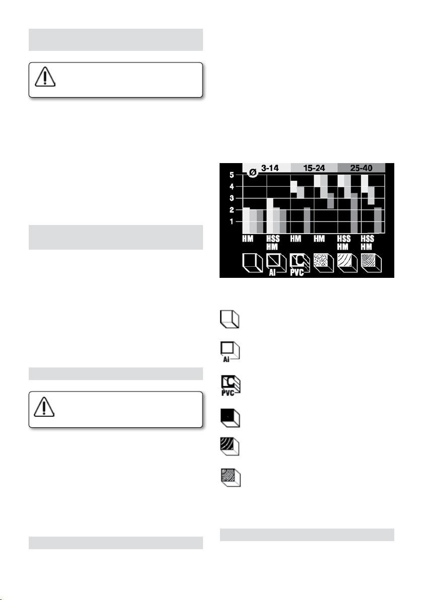
Tabla recomendada para seleccionar la velocidad de
acuerdo al material de trabajo y diámetro de fresa.
Simbología de materiales
Tableros de yeso, mampostería liviana
Aluminio
Verifique siempre que el voltaje de su red
eléctrica es el mismo que el voltaje indicado en la placa técnica de la máquina.
Encendido y apagado on/off del interruptor.
Encendido: Presione el botón de desbloqueo 8 (Fig. 8),
y luego presione la palanca de encendido 9 (Fig. 8).
Operación continua: Cuando la herramienta esté encendida presione más el botón 8 y bloquee el interruptor.
Presione el botón 8 y la palanca 9 hasta el final, luego
libere la palanca 9 y el botón 8.
Apagado: Presionando nuevamente la palanca 9 usted
puede apagar la máquina.
18. VELOCIDAD VARIABLE (TIPO FR278R)
Girando el botón 5 (Fig. 1) se puede variar la velocidad
desde 6000 hasta 27000 rpm.
Plásticos
Paneles aglomerados
Maderas suaves
Maderas duras
Encuentre la velocidad adecuada para su material de
trabajo por medio de una prueba práctica.
19. USO DE LA GUÍA PARALELA
Coloque la guía lateral 20 (Fig. 7) insertando los ejes
en los agujeros de la base 3 (Fig. 7), y ajustándolos a
la distancia deseada por medio de los pomos 2 (Fig. 7).
5
Page 6

Utilice el botón 18 para un ajuste más exacto sujetando
los dos tornillos 17 y aflojando los tornillos 19. Girando
el botón 18 (Fig. 7) usted puede mover las guías. Al girar
completamente la tuerca la distancia desplazada es de
1,25 mm. Apriete los tornillos 19 (Fig. 7) después del ajuste.
20. UTILIZACIÓN DE LAS GUÍAS PLANTILLAS
Las guías plantilla son utilizadas para el fresado de una
gran variedad de formas. La guía plantilla escogida 26
(Fig. 1) se sujeta a la base 3 (Fig. 1) por medio de los dos
tornillos de M5 que se entregan. Al realizar un copiado
aparece una diferencia de tamaño entre la plantilla y
la pieza fresada. Hay que tener siempre en cuenta la
diferencia entre el radio de la guía plantilla 13 (Fig.
11), y el de la herramienta al confeccionar la plantilla.
21. FRESADO CIRCULAR CON COMPÁS (Fig. 9)
Fije el compás 22 a uno de las columnas 27 ajustándolo
con la tuerca mariposa. Inserte la columna en uno de
los agujeros de la base de la máquina. Seleccione la
distancia deseada entre la fresadora y el punto de giro,
y fíjelo con el pomo 2 (Fig. 9).
22. SUJETANDO Y GUIANDO LA HERRAMIENTA
Sujete la herramienta con ambas manos mientras trabaja.
Enciéndala únicamente cuando la fresadora no toca la
superficie de la pieza de trabajo.
Antes que la fresadora alcance la pieza de trabajo, ésta
debe estar encendida.
No aplique presión sobre la herramienta mientras trabaja,
déjela que haga el trabajo por usted.
No incline la herramienta para evitar un fresado irregular.
Mantenga limpias y descubiertas las rejillas de ventilación del motor.
Al trabajar con la fresadora siga el siguiente orden:
1. Escoja una fresa y fíjela en la pinza.
2. Seleccione la profundidad deseada.
3. Ponga en marcha la herramienta.
4. Presione el motor hacia abajo y fije la palanca de
bloqueo.
5. Realice el fresado.
6. Libere el bloqueo
7. Apague la herramienta.
Dirección de desplazamiento de la máquina (Fig. 12)
Al fresar usted debe tener cuidado de la dirección
correcta de desplazamiento de la máquina respecto a
la pieza de trabajo.
Mueva la máquina en sentido opuesto al giro de la fresa.
Uso del tope giratorio
Al fresar en grandes profundidades, le recomendamos
hacerlo en fases a lo largo del meterial. Utilizando el tope
giratorio usted puede realizar el fresado en 2 o 3 fases o pases.
Seleccione la profundidad de fresado a la profundidad
máxima deseada 16 (Fig. 1). Luego realice fresados
intermedios utilizando pases a menor profundidad.
6
23. CAMBIO DE ESCOBILLAS
Es importante sustituir las escobillas cuando tengan una
longitud mínima de 5 mm.
Cambio de escobillas:
1. Desconectar la máquina de la red eléctrica.
2. Quitar los tornillos de la tapa.
3. Retirar con precaución el circuito electrónico (Sólo
en el modelo FR278R)
4. Extraer los portaescobillas y las escobillas.
5. Reemplazar las escobillas y montar el portaescobillas en
su alojamiento, comprobando que presione suavemente
sobre el colector.
6. Volver a montar como se ha indicado anteriormente.
Es aconsejable, mantener la máquina en marcha durante
unos 15 minutos una vez cambiadas las escobillas.
Si el colector presenta quemaduras o resaltes, se recomienda hacerlo reparar en un servicio técnico VIRUTEX.
Para esta operación no utilizar nunca papel esméril.
24. ACCESORIOS OPCIONALES
Opcionalmente pueden suministrarse los siguientes
accesorios opcionales:
7722116 Reductor de Ø 8 a 6 mm.
7722115 Reductor de Ø 8 a 6,35 mm (1/4").
6446073 Acoplamiento aspiración estandar 2,25 m.
7722123 Guía para lazo paso 26 mm.
7722161 Guía para lazo paso 16 mm.
7722162 Guía para lazo paso 34 mm.
7722160 Guía para plantilla AGB de herrajes oscilobatientes.
7722342 Guía plantilla para AGB 11-12
7740117 Fresa para plantilla AGB.
25. NIVEL DE RUIDO Y VIBRACIONES
Los niveles de ruido y vibraciones de esta herramienta
eléctrica han sido medidos de acuerdo con la Norma
Europea EN 60745-2-17 y EN 60745-1 y sirven como base
de comparación con máquinas de semejante aplicación.
El nivel de vibraciones indicado ha sido determinado para
las aplicaciones principales de la herramienta, y puede ser
utilizado como valor de partida para la evaluación de la
exposición al riesgo de las vibraciones. Sin embargo, el
nivel de vibraciones puede llegar a ser muy diferente al
valor declarado en otras condiciones de aplicación, con
otros útiles de trabajo o con un mantenimiento insuficiente
de la herramienta eléctrica y sus útiles, pudiendo llegar
a resultar un valor mucho más elevado debido a su ciclo
de trabajo y modo de uso de la herramienta eléctrica.
Por tanto, es necesario fijar medidas de seguridad de
protección al usuario contra el efecto de las vibraciones,
como pueden ser mantener la herramienta y útiles de
trabajo en perfecto estado y la organización de los
tiempos de los ciclos de trabajo (tales como tiempos
de marcha con la herramienta bajo carga, y tiempos de
marcha de la herramienta en vacío y sin ser utilizada
Page 7

realmente ya que la reducción de estos últimos puede
disminuir de forma sustancial el valor total de exposición).
26. GARANTÍA
Todas las máquinas electroportátiles VIRUTEX, tienen
una garantía válida de 12 meses a partir del día de su
suministro, quedando excluidas todas las manipulaciones
o daños ocasionados por manejos inadecuados o por
desgaste natural de la máquina. Para cualquier reparación
dirigirse al servicio oficial de asistencia VIRUTEX S.A.
27. RECICLAJE DE LAS HERRAMIENTAS ELÉCTRICAS
Nunca tire la herramienta eléctrica con el resto de residuos domésticos. Recicle las herramientas, accesorios y
embalajes de forma respetuosa con el medio ambiente.
Respete la normativa vigente de su país.
Aplicable en la Unión Europea y en países europeos
con sistemas de recogida selectiva de residuos:
La presencia de esta marca en el producto o en el
material informativo que lo acompaña, indica que al
finalizar su vida útil no deberá eliminarse junto con
otros residuos domésticos.
Conforme a la Directiva Europea 2002/96/CE los usuarios
pueden contactar con el establecimiento donde adquirieron el producto, o con las autoridades locales pertinentes,
para informarse sobre cómo y dónde pueden llevarlo
para que sea sometido a un reciclaje ecológico y seguro.
VIRUTEX se reserva el derecho de modificar sus productos
sin previo aviso.
1. TECHNICAL DATA
Type.........................................................FR277R
Universal motor.........................................50/60 Hz
Input power..................................................1010W
No-load speed.......................................24,000/min
Standard chuck diameter.................................8 mm
Routing depth............................................0-50 mm
Maximum bit diameter...................................40 mm
Revolving depth gauge...3-position depth adjustment
Weight..........................................................2.9 Kg
Weighted equivalent continuous
acoustic pressure level A.............................................91 dBA
Acoustic power level A..................................................102 dBA
Uncertainty...................................................................K = 3 dbA
Wear ear protection!
Vibration total values..............................................ah: 4.4 m/s
Uncertainty....................................................................K: 1.5 m/s
Type........................................................FR278R
Universal motor.........................................50/60 Hz
Input power..................................................1300W
No-load speed.............................6,000-27,000/min
Standard chuck diameter.................................8 mm
Routing depth.............................................0-50 mm
Maximum bit diameter...................................40 mm
Revolving depth gauge..3-position depth adjustment
Weight.............................................................3 Kg
Weighted equivalent continuous
acoustic pressure level A.............................................91 dBA
Acoustic power level A..................................................102 dBA
Uncertainty...................................................................K = 3 dbA
Wear ear protection!
Vibration total values..............................................ah: 4.4 m/s
Uncertainty....................................................................K: 1.5 m/s
2
2
2
2
ENGLISH
FR277R ROUTER
FR278R ELECTRONIC ROUTER
(ILUSTRATIONS IN PAGE 43)
Important
Read these OPERATING INSTRUCTIONS and
the attached GENERAL SAFETY INSTRUCTIONS
LEAFLET carefully before using the machine.
Make sure you have understood them before
operating the machine for the first time.
Keep both sets of instructions for any future
queries.
2. OPERATION RANGE
The router is a professional power tool intended for
surface milling of wood, plastics and aluminium. It is an
excellent tool for milling templates, contours, circles and
grooves, for making finishing laths and picture frames
and for engraving inscriptions.
3. SAFETY INSTRUCTIONS FOR
MACHINE OPERATION
Read the instructions for use and safety instructions
carefully before using the tool.
• Disconnect the plug before you perform any work
on the tool.
• Do not use the tool if the mains lead is damged. If the
mains lead is damaged while working, do not touch it
7
Page 8

but immediately disconnect the plug.
• Always keep the mains lead away from moving parts
of the tool.
Direct the mais lead to the rear fo the tool.
• Use only extension cord that is intended for outdoor
use and equipped with a splash-proof coupling-socket.
Connect the tool via a fault current (FI) circuit beaker
with a triggering current of 30 mA maximum.
• Wires of the extension cable must have a minimum
section of 1,5 mm2 and the cable must be fully unwound.
• Plug in the tool only if the switch is turned off.
• Always wear personal protective equipment, glasses
and footwear.
• Always hold the router with both hands.
• Switch off the motor after you have finished milling.
• Before you put down the tool, loosen the router table.
• Always put down the tool on a horizontal and clean
surface.
• Do not put any other tools on the workpiece.
• Workpiece must be clean, without any rests of ma-
terials, sawdust...
• Work place should have adequte lights, it is forbiidden
to use the tool in rooms with inflammable substances
and gases, switch on/off the tool only by the switch and
not by disconnesting the plug.
• Be careful of screws, nails and other objects in the
workpiece while milling.
• Start working only when the tool has reached full speed.
• Be aware of the sudden impact when the FR277R and
FR278R power tool is switched on.
• Prevent unintentional switching on of the tool.
• Always use undamaged and sharp router bits.
• When you do not use the tool, store it in a dry place
protected from dust.
• Do not wear loose clothes of jewelry the tool could
take hold of and pull it towards it. If you have long hair,
wear a protective head-covering. When working outside,
wear non-skid footwear.
• In case the tool is blocked, immediately switch off the
tool and disconnect the plug.
• Clamp the workpiece.
• Guide only switched on tool towards the workpice.
Switch off the tool when you when you have lifted the
tool from the workpiece.
• Use only original parts and accessories.
4. PACKAGE CONTENTS
Router
Parallel guide
Compass
Wrench
Dust extraction adapter
Instructions for use, guarantee card
8
5. PREPARING THE TOOL FOR MILLING
Always disconnect the plug from power
source before making any adjustments
or changing any accessory.
6. DUST SUCTION
Milling and grinding wood generate sawdust and dust
that endanger safety and health. Using dust suction
prevents air pollution for breathing and makes easier
removal of wastes.
7. MOUNTING DUST EXTRACTION ADAPTER
Put the dust extraction adapter 15 (Fig. 2) baseplate 3
(Fig. 2) so that the twin column guide A (Fig. 2) is inside
the mouth of the dust extraction adapter.
Push the mouth with the right hand thumb in the
direction A (Fig. 2) towards the locking edge C so that
the lock D on the periphery is automatically cought in
the edge B (Fig. 2)
Connect the hose of a vacuum cleaner directly to the
dust extraction adapter 15 (Fig. 3), or connect it with a
suction hose with a turning connection for extracting
dust 4 (Fig. 3).
Fix the latter into the corresponding place below the
motor cover.
Mount the upper dust extraction adapter by pushing
it in the directions C until it snaps between the motor
gerabox and the motor cover. Then attach the lower
part of the hose to the dust extraction adapter 15 in
the direction D (Fig. 3).
Turning connection enables better view of the milling
area and setting the vacuum cleaner hose in the most
favourable position. The diameter of the dust extraction adapter is 35 mm, which corresponds to hoses of
standard vacuum cleaners.
Using STANDARD DUST COLLECTOR ATTACHMENT
Ref.6446073 (optional), the router may be connected
to our AS182K, AS282K, AS382L aspirator or to any
other industrial aspirator via the aspiration connector.
8. REMOVING UPPER DUST
EXTRACTION ADAPTERS (Fig. 3)
With the hose can be removed by first taking off the hose
from the dust extraction adapter 15 in the direction E,
and then push with the left hand thumb the upper part
of the dust extraction adapter in the direction F (Fig. 3).
9. REMOVING LOWER DUST
EXTRACTION ADAPTERS (Fig. 2)
Take off the hose of the dust extraction adapter 4. Press
the lock D on the periphery of the adapter 15 that much
Page 9
to release it and push in the direction of the arrow B.
Then take off the adapter (Fig. 2)
14. ROUGH DEPTH ADJUSTMENT
10. CHOOSING A ROUTER
Always use router bits of such diameters that
correspond the lock collet. The number of revolutions must not be higher then the allowed
speed of the router. It is forbidden to use
router bits of diamenters larger than 40 mm.
Carbide tipped bits (HM) are suitable for working hard
materials and enable higher cutting speeds.
11. CLAMPING ROUTER BITS
Always disconnect the plug from power
source before making any adjustments
or changing any accessory.
Clamp the bit with the collet 25 (Fig. 1) and the nut 13
(Fig. 1). The correct order for clamping bits:
• Unscrew the nut with the inserted collet on the spindle
by 1-2 threads.
• Insert a bit. The bit must be inserted at least 20 mm
deep. Pushing the lock-off button 12 (Fig. 1, 4) you block
the spindle, and then fasten the clamp nut 13 (Fig. 1)
with the fork wrench 23 (Fig. 1). Excessive fastening of
the nut can damage the thread on the spindle.
• Never drive in the clamp nut 13 till the end of the
shaft when there is no bit in the collet. Danger of
damaging the collet!
When removing the bit with one turn, first loosen the
clamp nut 13 (Fig. 1), and then continue unscrewing it
till the bit is completely loose.
12. CHANGING CLAMPING COLLET
Collet must be fixed in the clamp nut 13 (Fig. 10). When
you want to change it, pull it from the nut using a small
screwdriver which you insert between the nut and the
collet. Insert a new collet with a strong push into the
clamp nut (click).
Collet must be inserted in the nut in such
manner that the nut and the collet are
even at the front side.
13. FIXING ROUTER TABLE
Fix the router table to the desired height by the lever
24 (Fig. 5). Built-in telescopic spring returns the router
table in the original position after releasing the lever.
Always disconnect the plug from power
source before making any adjustments
or changing any accessory.
Set the depth of milling by the screws on the chip
deflector 16 (Fig. 6), together with the adjusting bit
10 (Fig. 6) by indicator 28 (Fig. 6). the three screws on
the chip deflector enable pre-setting of three depths
of milling. The range of setting is 50 mm.
Put the rpiter on the workpiece.
Release the lever 24 (Fig. 5) and slowly push down the
tool. When the router touches the surface, pull the
lever 24 (Fig. 5).
Turn the chip deflector 16 (Fig. 6) to the most favourable
depth of milling.
Unscrew the wing screw 11 (Fig. 6) and thereby you
loosen the movement of the adjusting bit 10.
Push down the adjusting bit 10 (Fig. 6) so that it is set
on the screw on the chip deflector.
Set the depth indicator 28 (Fig. 6) to 0.
Push the adjusting bit 10 (Fig. 6) upwards. When you
reach the desired depth on the scale 7 (Fig. 6), fasten
the wing screw 11 (Fig. 6).
Release the lever 24 (Fig. 5) and push the bit into the
new preadjusted position so that the adjusting bit 10
(Fig. 6) is laid on the screw and then pull the lever 24
(Fig. 5) again.
You must check the rough depth adjustmnet by a practical
test and then correct it if necessary.
15. FINE DEPTH ADJUSTMENT
Always disconnect the plug from power
source before making any adjustments
or changing any accessory.
Carry our fine depth adjustment if necessary. Having
set the rough depth adjustment you can set the desired
depth to 0.1 mm accurately by turning the knob of the
adjusting bit (1 line = 0.1 mm).
First release the lever 24 (Fig. 5). While you are pushing
the tool down, press the upper button of the adjusting
bit in the direction G (Fig. 6), so that it is laid on the
screw on the revorverskem nastavku 16 (Fig. 6). Adjust
the lower button with the upper one, then turn the
upper button in the direction H for a desired value. Pull
again the lever 24 (Fig. 5)
16. FINE DEPTH ADJUSTMENT WITH
THE ROUTER FIXED IN A TABLE
Support the adjusting bit 10 (Fig. 6) on the screw of the
9
Page 10

chip deflector by a hollow screw and a spring.
Fasten the hollow screw 14 (Fig. 6) to the adjusting bit
10. Pay attention to put the screwdriver in the inside
of the adjusting bit into the groove of the screw below
the nut 14. Pushing the cover of the tool you set the
approximate depth of cut and fasten the screw 11 (Fig.
6). Fine depth adjustment is carried out by turning the
upper lever in the direction H (Fig. 6).
Check the accuracy by a practical test or correct it
correspondingly.
17. WORK WITH THE ROUTER
Symbols of materials
Gypsum boards
Aluminium
Plastics
Always check that the supply voltage
is the same as the voltage indicated on
the nameplate.
Switch on/off.
Switch on: Press the lock-off button 8 (Fig. 8), and then
press the switch lever 9 (Fig. 8).
Continuous operation: When the tool is switched on,
push further button 8 and lock-off the switch. Press
button 8 and lever 9 to the end, then first release the
lever 9 and the then button 8.
Switch off: Pressing again the switch lever 9 you switch
off the tool.
18. FULL WAVE VARIABLE SPEED (TYPE FR278R)
Adjusting button 5 (Fig. 1) enables variable speed from
6000 to 27000 rpm.
Constant electronics
• Enables milling of all sorts of wood, laminates, plastics
and aluminium.
• Enables constant set number of revolutions at heavy
loads.
• Enables setting optimal working revolutions.
• Prolongs the service lives of routers.
• Soft start of the tool and overload protection.
• Enables corresponding adjustment and greater safety
when milling with rezkarji of large diameters.
Recommended table for choosing the number of revolutions regarding the worked material and bit's diameter
Panel
Softwood
Hardwood
Find out the corresponding number of revolutions by
a practical test.
19. USING PARALLEL GUIDE
Fix the parallel guide 20 (FIg. 7) by inserting the adjusting
bits in the holes in the base plate 3 (Fig. 7). and fasten
them to the desired depth by two wing screws 2 (Fig. 7).
Use knob 18 (Fig. 7) for more accurate depth adjustment
by fixing the two wing screws 17 and loosening wing
screws 19. Turning the button 18 you are moving the
bit away or close to the guide. When you fully turn the
nut, the distance changes by 1.25 mm. Fasten the two
screws 19 (Fig. 7) after the adjustment.
20. USE OF TEMPLATE GUIDES
Template guides are used for copy cutting of richly shaped
patterns. Selected template guide 26 (Fig. 1) is fixed to
base 3 (Fig. 1) using the two screws. When copying, a
diffrence in size between the template and the routed
item becomes apparent. The difference between the
radius of the template guide 13 (Fig. 11) and the radius
of the tool must always be taken into account when
preparing the template.
21. CIRCULAR MILLING WITH COMPASSES (Fig. 9)
Fix the compasses 22 to one of the depth adjusters 27
fasten the point with a wing nut. Insert the composed
compasess into one of the holes in the baseplate of the
router. Set the desired distance between the router and
the compasses' point, and fasten it with a wing nut.
22. HOLDING AND GUIDING THE TOOL
10
Hold the tool with both hands while working. Switch
Page 11

on the tool only when the router does not touch the
surface of the workpiece.
Before the router reaches the workpiece, the tool should
be switched on.
Do not apply pressure on the tool while working, let the
tool do the work for you.
Do not tilt the tool in order to avoid uneven milling.
Keep the ventilation slots uncovered.
Follow the next order when working with the router:
1. Choose abit and clamp it into the collet chuck.
2. Set the desired depth of milling.
3. Switch on the tool.
4. Push the motor downwards, pull the lock lever.
5. Start milling.
6. Release lock-off.
7. Switch off the tool.
Direction of moving the tool (Fig. 12)
While milling you must pay attention to the right
direction of moving the tool regarding the workpiece.
Move the router in the opposite direction of the bit's
turning (protitek).
Using chip deflector
When milling large depths, we recommend to mill in
stages by small depths odvzemi materiala. Using the
revolverskega nastavka, you can divide milling into
two or three stages.
Set the desired depth depth of milling to the maximum
depth of milling 16 (Fig. 1). Start the first two millings
at higher setting levels.
23. BRUSHES AND COLLECTOR
It is important to change the brushes when they reach
a minium length of 5 mm.
Changing brushes.
1. Disconnect the machine from the mains.
2. Remove screws from the cover.
3. Carefully remove electronic circuit (only in model
FR278R).
4. Take brush-holder and the brush.
5. Replace the brushes and replace the brush-holder
in its housing, ensuring that it exerts a slight pressure
on the collector.
6. Reassemble as indicated above. It is advisable to
operate the machine for about 15 minutes once the
brushes have been changed.
If burns or wear and tear are seen on the collector, it
is recommended that it should be repaired by VIRUTEX
technical service.
Never use emery paper for this operation.
7722123 Dovetailing guide 26 mm.
7722161 Dovetailing guide 16 mm.
7722162 Dovetailing guide 34 mm.
7722160 AGB template guide for botton-hung fittings.
7722342 AGB template guide
7740117 Bit for AGB template.
25. NOISE AND VIBRATION LEVEL
The noise and vibration levels of this device have been
measured in accordance with European standard EN
60745-2-17 and EN 60745-1 and serve as a basis for comparison with other machines with similar applications.
The indicated vibration level has been determined for
the device’s main applications and may be used as an
initial value for evaluating the risk presented by exposure to vibrations. However, vibrations may reach levels
that are quite different from the declared value under
other application conditions, with other tools or with
insufficient maintenance of the electrical device or its
accessories, reaching a much higher value as a result
of the work cycle or the manner in which the electrical
device is used.
Therefore, it is necessary to establish safety measures
to protect the user from the effects of vibrations, such
as maintaining both the device and its tools in perfect
condition and organising the duration of work cycles
(such as operating times when the machine is subjected
to loads, and operating times when working with no-load,
in effect, not in use, as reducing the latter may have a
considerable effect upon the overall exposure value).
26. WARRANTY
All VIRUTEX power tools are guaranteed for 12 months
from the date of purchase, exlcuding any domage which
is a result of incorrect use or of natural wear and tear
on the machine. All repairs should be carried out by the
official VIRUTEX technical assistance service.
27. RECYCLING ELECTRICAL EQUIPMENT
Never dispose of electrical equipment with domestic waste. Recycle equipment, accessories and packaging in ways
that minimise any adverse effect on the environment.
Comply with the current regulations in your country.
Applicable in the European Union and in European
countries with selective waste collection systems:
If this symbol appears on the product or in the accompanying information, at the end of the product's useful
life it must not be disposed of with other domestic waste.
24. OPTIONAL ACCESSORIES
The following optional accessories can be supplied:
7722116 Reducer of Ø 8 to 6 mm
7722115 Reducer of Ø 8 to 6.35 mm (1/4")
6446073 Standard dust collector attachment 2.25 m.
11
Page 12

In accordance with European Directive 2002/96/EC, users
may contact the establishment where they purchased the
product or the relevant local authority to find out where
and how they can take the product for environmentally
friendly and safe recycling.
VIRUTEX reserves the right to modify its products
without prior notice.
FRANÇAIS
DÉFONCEUSE FR277R
DÉFONCEUSE ÉLECTRONIQUE FR278R
(FIGURES EN PAGE 43)
Important
Avant d'utiliser la machine, lisez attentivement ce MANUEL D'INSTRUCTIONS et la
BROCHURE D'INSTRUCTIONS GÉNÉRALES
DE SÉCURITÉ qui vous sont fournis avec
cette machine. Assurez-vous de bien
avoir tout compris avant de commencer
à travailler sur la machine.
Gardez toujours ces deux manuels
d'instructions à portée de la main pour
pouvoir les consulter, en cas de besoin.
1. DONNÉES TECHNIQUES
Modèle.....................................................FR277R
Moteur universel........................................50/60 Hz
Puissance....................................................1010 W
Vitesse à vide.........................................24.000 /min
Diamètre pince standard.................................8 mm
Profondeur de fraisage...............................0-50 mm
Diamètre maximal de la fraise..........................40mm
Calibre de profondeu rotatif........réglage de profondeur
à 3 positions avec échelle
Poids...........................................................2,9 Kg
Niveau de pression acoustique
continu équivalent pondéré A..........................................91 dBA
Niveau de puissance acoustique A...............................102 dBA
Incertitude.....................................................................K = 3 dbA
Porter une protection acoustique!
Valeurs totales des vibrations..................................ah: 4,4 m/s
Incertitude..................................................................K: 1,5 m/s
Modèle.....................................................FR278R
Moteur universel........................................50/60 Hz
Puissance....................................................1300 W
Vitesse à vide...............................6.000-27.000/min
12
Diamètre pince standard................................8 mm
Profondeur de fraisage...............................0-50 mm
Diamètre maximal de la fraise..........................40mm
Calibre de profondeu rotatif..........réglage de profondeur
à 3 positions avec échelle
Poids..................................................................3 Kg
Niveau de pression acoustique
continu équivalent pondéré A..........................................91 dBA
Niveau de puissance acoustique A...............................102 dBA
Incertitude.....................................................................K = 3 dbA
Porter une protection acoustique!
Valeurs totales des vibrations..................................ah: 4,4 m/s
Incertitude..................................................................K: 1,5 m/s
2. EMPLOI
La défonceuse est un outil éléctrique professionnel conçu
pour le fraisage superficiel du bois, des masses artificielles
et de l'aluminium. C'est aussi un outil excellent pour le
fraisage des échantillons, des contours, des cercles et
des rainures, pour la fabrication des lattes de finition,
de listels et pour les gravures des inscriptions.
3. INSTRUCTIONS DE SÉCURITÉ POUR
LE MANIEMENT DE LA MACHINE
Avant de se mettre au travail lisez les instructions d'emploi
et conservez-les dans un lieu approprié.
• Débrancher l'outil de la source d'alimentation avant
de procéder à n'importe quelle manipulation de l'outil.
• N'utilisez pas l'outil avec le cordon endommagé. Si
le cordon de branchage s'abîme lors du travail, ne le
touchez pas! Débranchez immédiatement le cordon de
la prise de courant.
• Gardez toujours le cordon à bonne distance des parties
mobiles de l'outil.
Lors du travail le cordon doit se trouver en tout temps
derrière l'outil.
• Pour le travail à l'extérieur il est recommendé d'utiliser
le cordon de rallonge, protégé des éclabousures d'eau.
Branchez l'outil à l'interrupteur éléctrique protégé (FI)
ayant le courant maximum 30 mA.
• Le cordon de rallonge doit en diamètre de conducteurs
mésurer au moins 1,5 mm2 et doit être, lors de l'usage,
complètement déroulé.
• Avant de brancher l'outil à une prise de courant,
rassurez-vous que l'interrupteur est enclenché!
• Portez en tout temps l'équipement de sécurité appro-
2
prié tel que les luntettes de sécurité, les guants et les
2
chaussures appropriées.
• Maniez la fraiseuse des deux mains!
• Après avoir fini le fraisage, éteignez le moteur.
• Avant de poser l'outil, relâchez la table de fraisage.
• Posez toujours l'outil sur une surface propre et
horizontale.
2
2
Page 13

• Ne posez pas d'autres outils sur la pièce à usiner.
• La pièce doit être propre, sans les copieaux ou le sciage...
• Le lieu de travail doit être adéquatement éclairé!.
N'utilisez pas les outils éléctriques en atmosphères
explosives en présence de liquides ou gaz inflammables!
Débranchez et branchez à la prise de courant toujours
en utilisant l'interrupteur!
• Lors du fraisage faites attention aux écrous, clous et
autres éléments étrangers dans la pièce.
• Procédez au travail dès que l'accessoire a atteint le
régime choisi.
• Lors de la mise en marche de l'outil FR277R, FR278R,
méfiez-vous du rebond.
• Évitez la mise en marche accidentelle.
• Utilisez en tout temps les fraises tranchantes et intactes!
• Rangez l'outil quand il ne sert pas! Il doit être rangée
dans un endroit sec, protégé de la poussière.
• Potez des vêtements convenambes! Ne portez pas
des vêtements amples ni des bijoux car ils risquent de
s'accrocher dans les pièces mobiles. Pour des cheveux
longs nous conseillons le port d'un serre-tête. Lors du
travail à l'extérieur portez des chausseures à semmelle
antidérapante.
• Si l'outil s'arrète durant le fonctionnement, mettez
immédiatement l'interrupteur en position d'arrêt et
débranchez l'outil de la prise de courant.
• Attachez la pièce à usiner.
• Approchez la pièce seulement si l'outil est mis en
marche!. Arrêtez l'outil quand il est à bonne distance
due la pièce à usiner.
• Utilisez les accessoires et parties originales.
4. LE CONTENU DE L'EMBALAGE
Défonceuse
Guide latéral
Compas
Clé de service
Tuyeau d'aspiration
Mode d'emploi, et certificat de garantie
5. PRÉPARATION DE L'OUTIL
7. MONTAGE DE RACCORD DE L'ASPIRATEUR
Placez le raccord de l'aspirateur 15 (Fig. 2) sur la plaque
de dessous 3 (Fig. 2) de façon que les raccords de guide
restent A (Fig. 2) dans l'orifice du raccord de l'aspirateur.
Appuyez avec le pouce droit sur l'orifice en direction A
(Fig. 2) de bord C pour que le loquetau sur le cercle D
s'enclenche automatiquement B (Fig. 2).
Vouz pouvez attacher le tuyau de l'aspirateur directement
sur le raccord de l'aspirateur 15 (Fig. 3) oubien vouz
pouvez le relier, en utilisant le tuyau de l'aspirateur,
avec le raccord d'aspiration pivolant 4 (Fig. 3).
Le raccord pivotant doit être placé dans l'endroit monté
au dessous du tablier du moteur.
Montez le raccord supérieur de tuyau d'aspirateur de
façon de la poussez en direction C, jusqu'à ce que il ne
s'enclenche entre le capot et le tablier. Placez ensuite la
partie inférieure du tuyau sur le raccord de l'aspirateur
15 en direction D (Fig. 3).
Le raccord pivotant permet le contrôle plus grand sur l'aire
de fraisage et le placement du tuyau de l'aspirateur dans
la position la plus adéquate. Le raccord de l'aspirateur a
le diamètre 35 mm, ce qui convient les tuyaux standard
pour les aspirateurs.
À l'aide du connecteur d'aspiration, la fraiseuse peut
être connectée, moyennant un ACCOUPLEMENT
D'ASPIRATION STANDARD Réf.6446073 (optionnel), à
notre aspirateur AS182K, AS282K, AS382L ou à tout
autre aspirateur industriel.
8. DÉTACHEMENT DES RACCORDS
SUPÉRIEUR DE L'ASPIRATEUR (Fig. 3)
De façon de détacher le tuyau 15 en direction E, ensuite
appuyez avec le pouce gauche sur la partie supérieure
du raccord en direction F (Fig. 3)
9. DÉTACHEMENT DES RACCORDS
INFÉRIEUR DE L'ASPIRATEUR (Fig. 2)
Détachez le tuyau du raccord 4. Appuyez sur le loquetau
D sur le cercle de connextion 15 pour que vous puissiez
déclencher la prise et poussez en direction de la flèche
B. Ensuite détachez le raccord (Fig. 2).
Débrancher l'outil de la source
d'alimentation avant de procéder à
n'importe quelle manipulation de l'outil.
6. ASPIRATION DE LA POUSSIERE
Lors du fraisage ou brossage du bois il se produit du
sciage et de la poussière qui puissent compromettre
la sécurité et la santé du travailleur. L'aspiration de la
poussière previent la pollution de l'air, qui est difficile
à réspirer, et facilite l'élimination des copeaux.
10. LA CHOIX DES FRAISES
Utilisez toujours les fraises dont le diamètre de la hampe correspondent au
dispositif de serrage. La vitesse de rotation
de l'outil ne doit pas être supérieure à la
vitesse de rotation admissible de la fraise.
N'utilisez pas les fraises dont le diamètre
est supérieur à 40 mm!
Les fraises avant la partie dure en carbure (HM) sont
13
Page 14

approprié pour le travail des matériaux plus durs et
permettent les vitesses de fraisage plus grandes.
11. LE SERRAGE DES FRAISES
Débrancher l'outil de la source
d'alimentation avant de procéder à
n'importe quelle manipulation de l'outil.
Serrez la fraise dans le dispositif 25 (Fig. 1) et l'écrou
13 (Fig. 1) dans l'ordre suivant:
• Le dispositif est inséré dans l'écrou et le tout est vissé
sur l'arbre. Devisser l'écrou de 1-2 filets.
• Insérez la fraise. La hampe de la fraise doit être placé
au moins 20 mm en profondeur. En appuyant sur le
bouton d'arrêt 12 (Fig. 1, 4) bloquez l'arbre, ensuite avec
la clé fourchue 23 (Fig. 1) vissez l'écrou de serrage 13
(Fig. 1). Le vissage trop fort de l'écrou peut endommager
le filetage de l'arbre.
• L'écrou de serrage sans la fraise insérée ne doit etre
jamais vissé sur l'arbre à fond. Danger d'endommager
le dispositif!.
Pour le démonage de la fraise, devissez un peu l'écrou
de serrage 13 (Fig. 1), ensuite devissez jusqu'à ce que la
fraise n'est complètement déclenchée.
12. LE CHANGEMENT DU DISPOSITIF DE SERRAGE
Le dispositif est serré dans l'écrou de serrage 13 (Fig.
10). En changant le dispositif, retirez-le de l'écrou avec
un tourmevis petit que vous placez entre l'écrou et le
dispositif. Placez un dispositif nouveau de façon de le
presser fortement dans l'écrou de serrage (clic).
Le dispositif et l'écrou de serrage doivent
être nivelés sur le devant.
13. LE FIXAGE DE LA TABLE DE FRAISAGE
Fixez la table de fraisage au niveau désiré avec la manivelle 24 (Fig. 5). En relâchant la manivelle le ressort
téléscopique intégrant renvoie la table dans la position
originale.
14. LE RÉGLAGE BRUT DE LA
PROFONDEUR DE FRAISAGE
Débrancher l'outil de la source
d'alimentation avant de procéder à
n'importe quelle manipulation de l'outil.
Réglez la profondeur de fraisage en utilisant les vis sur
le raccord à révolver 16 (Fig. 6) et le bouchon de res-
14
triction 10 (Fig. 6) avec l'indicateur 28 (Fig. 6). Les trois
vis sur le raccord à révolver permettent l'avant-réglage
de trois profondeurs de fraisage. La circonference du
réglage est 50 mm.
Placez la fraiseuse sur la pièce à usiner.
Déclenchez la manivelle 24 (Fig. 5) et poussez doucement
l'outil vers le bas. Quand la fraiseuse touche la surface,
serrez la manivelle 24 (Fig. 5).
Réglez le raccord à révolver 16 (Fig. 6) à la profondeur
la plus appropriée.
Désserez le vis à ailettes 11 (Fig. 6) et en faisant celà
déclenchez le mouvement du bouchon de restriction 10.
Poussez le bouchon 10 (Fig. 6) vers le bas pour qu'il se
place sur le vis sur le raccord à révolver.
Placez l'indicateur de la profondeur 28 (Fig. 6) sur le 0.
Poussez le bouchon de restriction 10 (Fig. 6) vers le haut.
Quand l'échelle 7 (Fig. 6) indique la profondeur désirée,
serrez le vis à ailettes 11 (Fig. 6).
Relâchez la manivelle 24 (Fig. 5), en appuyant encore,
poussez la fraiseuse dans un avant-réglage noveau
jusqu'à le bouchon ne s'enclenche 10 (Fig. 6) sur le vis
et serrez de nouveau la manivelle 24 (Fig. 5).
Le réglage brut de la profondeur de fraisage doit être
contrôlé en faisant un essai et, si nécessaire, faire une
corréction.
15. LE RÉGLAGE PRÉCIS DE LA
PROFONDEUR DE FRAISAGE
Débrancher l'outil de la source
d'alimentation avant de procéder à
n'importe quelle manipulation de l'outil.
Le réglage précis de la profondeur de fraisage se fait en
cas de nécessité. Après le réglage brut réglez de profondeur désirée en torumant le bouton du bouchon ayant
la précision de 0,1 mm. (1 trait=0,1 mm).
D'abord délâchez la manivelle 24 (Fig. 5). En poussant
l'outil vers le bas, appuyez sur le bouton supérieur de
bouchon en direction de G (Fig. 6), pour que l'écrou puisse
se placer dans le vis de raccord à révolver 16 (Fig. 6).
Arrangez le bouton inférieur avec le bouton supérieur
et ensuite tournez le bouton supérieur en direction
H pour obtenir la valeur désiré. Serrez de nouveau la
manivelle 24 (Fig. 5).
16. LE RÉGLAGE PRÉCIS EN INSÉRANT
LA FRAISEUSE DANS LA TABLE
Appuyez le bouchon avec la douille et le ressort 10 (Fig.
6) sur le vis du raccord à révolver.
Serrez la douille qu filetage 14 (Fig. 6) sur le bouchon
10. Ajustez le vis à l'interieur du bouchon avec l'entaille
du vis au dessou de l'écrou 14. En appuyant sur le capot
de l'outil réglez la profondeur approximative du fraisage
Page 15

et serrez le vis 11 (Fig. 6). Le réglage précis se fait en
tournant la manivelle supérieure en direction de H (Fig. 6).
Contrôlez la précision du réglage en faisant un essai et,
si nécessaire, faites une correction.
17. LE TRAVAIL AVEC LA FRAISEUSE
Avant le travail rassurez-vous que la tension du circuit correspond à celle spécifiée
sur la plaquette emblématique.
Mise en marche/mise hors marche
Mise en marche: appuyez sur le bouton du méchanisme
de blocage 8 (Fig. 8), ensuite poussez la manivelle de
l'interrupteur 9 (Fig. 8).
Fonctionnement continu: l'interrupteur branché, mettez-le dans la position d'arret en appuyant le bouton 8.
Appuyez le bouton 8 et la manivelle 9 à fond, puis relachez
la manivelle 9, et ensuite relâchez aussi le bouton 8.
Mise hors marche: débranchez l'outil en appuyant de
nouveau sur la manivelle de l'interrupteur 9.
18. LA MISE AU POINT DE LA ROTATION
CONTINUELLE (TYPE FR278R)
Le bouton 5 (Fig. 1) permet la mise en point de la rotation
continue de 6000 à 27000 min-1.
L'éléctronique de régulation:
• Permet le fraisage de toutes sortes de bois, laminés
masses artificielles et l'aluminium.
• Permet la stabilité dès la mise en point de la rotation
n'importe la sollicitation.
• Permet le réglage de la rotation optimales.
• Prolonge la durée de vie des fraises.
• Permet le démarrage glissant de l'outil et une pro-
tection de surcharge.
• Permets une adaptabilité et sécurité plus grandes lors
du fraisage avec des fraises aux diamètres plus grandes.
Le tableau recommandant le choix de la mise en point
de la rotation en tenant compte du matériel et le diamètre de la fraise.
Symboles des matériaux
Plaques en plâtre
Aluminium
Plastique
Bois latté
Bois tendre
Bois dur
Le réglage de la rotation adéquate se vérifie en faisant
un essai.
19. L'UTILISATION DU GUIDE LATÉRAL
Attachez le guide latéral 20 (Fig. 7) de façon d'insérer
les deux bâtons guide dans les forures sur la plaque de
dessous 3 (Fig. 7) et serrez-les avec les vis à ailettes en
réglant aussi une distance désirée 2 (Fig. 7).
Pour le réglage plus précis appuyez le bouton 18 (Fig.
7), c'està-dire fixez les deux vis à ailettes 17 et relâchez
les vis 19. En tourant le bouton 18 (Fig. 7) la fraiseuse
se rapproche ou éloigne du guide. Avec chaque tour
complet de l'écrou la distance change de 1,25 mm. Aprèz
le réglage serrez les vis 19 (Fig. 7).
20. EMPLOI DE LA DOUILLE
On emploie la douille pour la coupure par reproduction,
surtout quand il s'agit d'un modèle à grande richesse
de contours. La douille choisi 26 (Fig. 1) se fixe sur la
base 3 (Fig. 1) avec les deux vis. En faisant une copie,
il apparaît une différence de taille entre le gabarit et
la pièce défoncée. Il faut toujours tenir compte de la
différence entre le rayon de la douille guidage 13 (Fig.
11) et celui de l'outil en faisant le gabarit.
21. LE FRAISAGE CIRCULAIRE AVEC
LE SIMBLEAU (FIG. 9)
Placez la bride du simbleau 22 sur un des bâtons de guide
27 attachez la pointe avec le vis à ailettes. Insérrez le
simbleau assemblé dans un des trous dans la plaque de
la fraiseuse. Réglez la distance désirée entre la fraise et
la pointe du simbleau et fixez-la avec la vis à ailettes.
15
Page 16

22. LA PRISE ET LE MANIEMENT DE L'OUTIL
Lors du travail maniez l'outil des deux mains. Branchez
l'interrupteur seulement quand la fraise ne touche pas
la surface de la pièce à usiner.
Avant que la fraise touche la pièce, l'outil doit être branché.
Ne pressez pas l'outil, faites travailler l'outil à votre place.
Ne penchez pas l'outil! Celà empêche le fraisage régulier
et uniforme de la pièce.
Ne couvrez pas les fentes de ventilation.
Lors fraisage on considère le processus suivant:
1. Choisissez la fraise et serrez-la dans le dispositif de
serrage.
2. Réglez le profondeur désirée du fraisage.
3. Branchez l'outil.
4. Appuyez le moteur vers le bas, serrez la manivelle
de blocage.
5. Fraisez.
6. Délachez le blocage.
7. Débranchez l'outil.
La direction de mouvement de l'outil (Fig. 12)
Lors du fraisage vous devez, en tenant compte de la
pièce à usiner, avancez l'outil dans la direction correcte.
Avancez l'outil en sens contraire à la rotation de la fraise
(la contre-marche).
Utilisation du raccord à révolver
Le fraisage en étapes avec plusieurs enlèvements du
matéril est recommandable en fraisant à une profondeur
plus grande. En utilisant le raccord à révolver vous pouvez
repartir le fraisage en deux ou trois niveaux.
Réglez la profondeur désirée 16 (Fig. 1). Commencez les
premiers deux fraisages en réglage plus élevé.
23. BALAIS ET COLLECTEUR
Il est important de changer les balais quand ils ont une
longueur minimum de 5 mm.
Changement des balais.
1. Débrancher la machine du secteur.
2. Enlever les vis du capuchon.
3. Retirer avec soin le circuit électronique (uniquement
sur le modèle FR278R).
4. Extraire le porte-balais et le balai.
5. Remplacer les balais et monter le porte-balais dans
son logement, en vérifiant qu'il fait légèrement pression
sur le collecteur.
6. Remonter le tout comme il est indiqué, ci-dessus. Il est
recommandé de laisser la machine en marche pendant
15 m après avoir changé les balais.
Si le collecteur présente des brûlures ou des ressauts,
il est recommandé de le faire réparer par un service
technique VIRUTEX.
Ne jamais utiliser de papier émeri pour cette opération.
24. ACCESSOIRES OPTIONNELS
En option, nous pouvons fournir les accessoires optionnels suivants:
16
7722116 Réducteur de diam. 8 à 6 mm.
7722115 Réducteur de diam. 8 à 6,35 mm (1/4")
6446073 Accouplement d'aspiration standard 2,25 m.
7722123 Guidage pour queue d'aronde pas 26 mm.
7722161 Guidage pour queue d'aronde pas 16 mm.
7722162 Guidage pour queue d'aronde pas 34 mm.
7722160 Guidage pour gabarit AGB.
7722342 Guidage pour gabarit AGB.
7740117 Fraise pour gabarit AGB.
25. NIVEAU DE BRUIT ET DE VIBRATIONS
Les niveaux de bruit et de vibrations de cet appareil
électrique ont été mesurés conformément à la norme
européenne EN 60745-2-17 et EN 60745-1 et font
office de base de comparaison avec des machines aux
applications semblables.
Le niveau de vibrations indiqué a été déterminé pour
les principales applications de l’appareil, et il peut être
pris comme valeur de base pour l’évaluation du risque
lié à l’exposition aux vibrations. Toutefois, dans d’autres
conditions d’application, avec d’autres outils de travail
ou lorsque l’entretien de l’appareil électrique et de ses
outils est insuffisant, il peut arriver que le niveau de
vibrations soit très différent de la valeur déclarée, voire
même beaucoup plus élevé en raison du cycle de travail
et du mode d'utilisation de l'appareil électrique.
Il est donc nécessaire de fixer des mesures de sécurité
pour protéger l'utilisateur contre les effets des vibrations,
notamment garder l’appareil et les outils de travail en
parfait état et organiser les temps des cycles de travail
(temps de fonctionnement avec l’appareil en service,
temps de fonctionnement avec l’appareil à vide, sans être
utilisé réellement), car la diminution de ces temps peut
réduire substantiellement la valeur totale d’exposition.
26. GARANTIE
Tous les machines électro-portatives VIRUTEX ont une
garantie velable 12 mois à partir de la date d'achat, en
étant exclus toutes manipulations ou dommages causés
par des maniements inadéquats ou par l'usure naturelle
de la machine. Pour toute réparation, s'adresser au service
officiel d'assistance technique VIRUTEX.
27. RECYCLAGE DES OUTILS ÉLECTRIQUES
Ne jetez jamais un outil électrique avec le reste des déchets ménagers. Recyclez les outils, les accessoires et les
emballages dans le respect de l'environnement. Veuillez
respecter la réglementation en vigueur dans votre pays.
Applicable au sein de l'Union Européenne et dans
les pays européens dotés de centres de tri sélectif
des déchets:
Ce symbole présent sur le produit ou sur la documentation informative qui l'accompagne, indique qu'en fin
de vie, ce produit ne doit en aucun cas être éliminé avec
le reste des déchets ménagers.
Page 17
Conformément à la directive européenne 2002/96/CE,
tout utilisateur peut contacter l'établissement dans
lequel il a acheté le produit, ou les autorités locales
compétentes, pour se renseigner sur la façon d’éliminer le
produit et le lieu où il doit être déposé pour être soumis
à un recyclage écologique, en toute sécurité.
VIRUTEX se réserve le droit de modifier ses produits
sans avis préalable.
DEUTSCH
TISCHFRÄSMASCHINE FR277R
ELEKTRO-TISCHFRÄSMASCHINE FR278R
(ABBILDUNGS IN SEITE 43)
Achtung!
Lesen Sie bitte vor Benutzung der Maschine die beiliegende GEBRAUCHSANWEISUNG und die ALLGEMEINEN SICHERHEITSHINWEISE sorgfältig durch.
Stellen Sie sicher, dass Sie sowohl die
Gebrauchsanweisung als auch die allegemeinen Sicherheitshinweise verstanden
haben, bevor Sie die Maschine bedienen.
Bewahren Sie beide Gebrauchsanweisungen zum späteren Nachschlagen auf.
1. TECHNISCHE DATEN
Modell......................................................FR277R
Universal motor..........................................50/60 Hz
Leistungsaufnahme.....................................1010 W
Leerlaufgeschwindigkeit......................24.000/min
Umgerechnetes akustisches
Durchmesser Standard-Spannfutter...............8 mm
Frästiefe....................................................0-50 mm
Maximaler Durchmesser der Fräse................40mm
Tiefendreh-lehre...Tiefeneinstellung von 3 Positionen
Gewicht.......................................................2,9 Kg
Gewichteter akustischer Dauerdruckpegel A.......91 dBA
Akustischer Druckpegel A.....................................102 dBA
Unsicherheit...............................................................K = 3 dBA
Gehörschutz tragen!
Schwingungsgesamtwerte....................................a
Unsicherheit.............................................................K = 1,5 m/s
: 4.4 m/s
h
Modell......................................................FR278R
Universal motor.........................................50/60 Hz
Leistungsaufnahme......................................1300 W
Leerlaufgeschwindigkeit............6.000-27.000/min
Durchmesser Standard-Spannfutter..............8 mm
Frästiefe...................................................0-50 mm
Maximaler Durchmesser der Fräse.................40 mm
Tiefendreh-lehre...Tiefeneinstellung von 3 Positionen
Gewicht..............................................................3 Kg
Gewichteter akustischer Dauerdruckpegel A.......91 dBA
Akustischer Druckpegel A.....................................102 dBA
Unsicherheit...............................................................K = 3 dBA
Gehörschutz tragen!
Schwingungsgesamtwerte....................................ah: 4.4 m/s
Unsicherheit.............................................................K = 1,5 m/s
2. ANWENDUNGSBEREICH
Die Fräse ist ein professionelles Werkzeug geeignet für
Fräsen von Holzoberflächen, Kunststoffmassen und
Aluminium. Es ist ein ausgezeichneter Hilfsmittel für
Fräsearbeiten mit Schablonen, Konturen und Nuten, für
die Fertigstellung von Deckleisten und Bildrahmenleisten,
wie auch für die Gravierung von Inschriften.
3. SICHERHEITSHINWEISE FÜR DIE
BEDIENUNG DER MASCHINE
Bitte diese Bedienungsanleitung sorgfältig lessen und
aufbewahren.
• Ziehen Sie grundsätzlich den Netzstecker, bevor Sie
beliebige Änderungen vornehmen.
• Werkzeug nicht weiter verwenden, wenn das Kabel bei
der Arbeit beschädigt ist. Kabel nicht berühren, sondern
sofort den Netzstecker ziehen.
• Halten Sie das Kabel immer von den rotierenden Teilen
Ihres Werkzeugs fern.
Führen Sie das Kabel immer nach hinten vom Werkzeug weg.
• Bei Aussenarbeiten nur die spritzwassergeschützte
Kabelverlängerung verwenden! Das Gerät muss über
den FI-Schutzschalter angeschlossen werden; max.
Differenzstrom 30 mA.
• Bei Benutzung von Verlängerungskabeln ist darauf zu
achten, dass das Kabel völlig abgerollt ist und Mindest-
querschnitt 1,5 mm
2
beträgt.
• Immer persönliche Schutzausrüstung wie Schutzbrille,
und Arbeitsschuhe tragen
• Die Fräse immer zweihändig leiten.
• Nach der Fräsenarbeit immer den Motor abschalten.
• Den Fräsentisch räumen, bevor Sie die Fräse absetzen.
• Die Fräse immer auf eine gerade und saubere Unter-
17
2
2
2
2
Page 18

lage ablegen.
• Legen Sie keine anderen Werkezuge auf das Werkstück.
• Das Werkstück muss sauber, ohne Sägenspäne sein.
• Der Arbeitsplatz muss entsprechend hell sein. Die
Benutzung des Gerätes ist in Räumen mit enflammbaren
Stoffen und Gasen nicht erlaubt. Das Gerät soll mit der
Taste eingeschaltet / ausgeschaltet werden und nicht
durch das Ziehen des Steckers aus der Steckdose.
• Beim Fräsen achten Sie auf Schrauben, Nägel und
andere Fremdkörper im Bearbeitungsmaterial.
• Beginnen Sie mit der Arbeit, nachdem das Gerät die
volle Drehzahl erreicht hat.
• Achten Sie auf den Stoss beim Einschalten des Gerätes
FR277R FR278R.
• Verhindern Sie eine unbeabsichtigte Einschaltung
des Gerätes.
• Benutzen Sie immer unbeschädigte und scharfe Fräser.
• Bei Nichtbenutzung des Gerätes, immer in trockenem
Raum staubgeschützt lagern.
• Tragen Sie keine lose Kledung oder Schmuck, die
das Gerät einfangen und einziehen könnte. Wenn Sie
lange Haare haben, tragen Sie eine Kopfbedeckung.
Bei Ausenarbeiten immer rutschfeste Schuhe tragen.
• Im Falle jeglichen Werkzeugstillstandes soll das Gerät
sofort abgeschlatet und der Stecker aus der Steckdose
herausgezogen werden.
• Das Werkstück befestigen.
• Bevor das Werkzeug das Werkstück berührt, muss
Ihr Werkzeug erst eingeschaltet werden. Vor dem
Ausschalten des Werkzeuges sollte dieses von Werkstück
abgenommen werden.
• Nur original - Zubehör verwenden
4. INHALT DER VERPACKUNG
Fräse
Seitenführung
Zirkel
Gabelschlüssel
Absaugadapter
Bedienungsanleitung, Garantieschein
5. VORBEREITUNG DES FRÄSEGERÄTES
7. ANSETZEN DES ABSAUGADAPTERS
Legen Sie den Absaugadapter 15 (Abb. 2) an die Fussplatte
3 (Abb. 2) so, dass die Leitansätze A (Abb. 2) im Inneren
der Absaugadaptermündung liegen.
Drücken Sie mit dem Daumen der rechten Hand die
Mündung in die Richtung A (Abb. 2) des Einfangrandes
C so, dass sich der Sperrriegel D am Umfang von alleine
am Rand B (Abb. 2) einfängt.
Das Staubaubsaugrohr kann man direkt an den Absaugadapter 15 (Abb. 3) anschlieβen oder es mit Hilfe des
Absaugrohres an den drehbaren Ansatz 4 (Abb. 3) der
Staubabsaugung verbinden.
Den letzten bringen Sie an die vorgesehene Stelle unter
der Motorhaube an.
Der obere Absaugadapter soll so montiert werden, damit
man ihm in die Richtung C, schieben kann, bis er zwischen dem Motorgehäuse und der Motorhaube einrastet.
Danach soll der untere Teil des Rohres an den Absaugadapter in der Richtung D (Abb. 3) eingesetzt werden.
Der drehbare Ansatz sichert eine bessere Übersicht des
Fräsegebietes und die günstigste Stellung des Staubabsaugrohres. Der Absaugadapter hat einen Durchmesser
von 35 mm, was den Anschlieβungen der Standardstaubabsaugungsrohren entspricht.
Über die Steckkupplung für die Absaugung kann die
Fräsmaschine mit Hilfe des STANDARDSAUGER-ANSCHLUSSES (Best.-Nr.6446073, Zubehör auf Wunsch) an
unseren Sauger AS182K, AS282K oder jedweden anderen
Industriesauger angeschlossen werden.
8. ENTFERNUNG DES ABSAUGADAPTERS (Abb. 3)
Oberer Absaugadapter (Abb. 3) kann mit dem Rohr so
entfernt werden, dass zuerst das Rohr aus dem Absaugadapter 15 in der Richtung E entfernt wird, dann drücken
Sie mit dem Daumen der rechten Hand am oberen Teil
des Absaugadapters in der Richtung F (Abb. 3).
9. UNTERER ABSAUGADAPTER (Abb. 2)
Das Rohr wird aus dem Absaugadapter 4 entfernt. Den
Sperrriegel D am Umfang des Anschlusses 15 so drücken,
dass der Griff gelöst wird und in die Richtung des Pfeiles
schieben B. Der Anschluss wird dann entfernt (Abb. 2).
Vor jeglicher Arbeit am Gerät Netzkabel
aus der Steckdose herausziehen
6. STAUBABSAUGUNG
Beim Fräsen, Schleifen, usw. am Holz enstehen Sägespäne und Staub, die die Gesundheit und Sicherheit
gefährden. Die Benutzung der Staubabsaugung verhindert die Atemluftbeschmutzung und erleichtert die
Abfallentsorgung.
18
10. FRÄSENAUSWAHL
Sie immer Fräser mit dem Durchmesser des
Schafts der der Spannhülse entspricht. Die Drehzahl des Gerätes darf nicht höher als die erlaubte
Geschwindigkeit der Fräser sein. Die benutzung
von Fräser mit dem durchmeser über 40mm
ist nicht erlaubt. Hartmetall Fräser sind für die
Bearbeitung von härteren Materialen geeinigt
und sichern höhere Fräsegeschwindigkeit.
Page 19
11. EINSPANNUNG DER FRÄSER
Vor jeglicher Arbeit am Gerät immer den
Stecker aus der Steckdose ziehen.
Den Fräser spannen sie mit Hilfe der Hülse 25 (Abb. 1)
und der Mutter 13 (Abb. 1) ein. Das Einspannen des Fräser
wird in der Regel nach folgenden Punkten ausgeführt:
• Lösen Sie die Mutter mit eingestzer Spannhülse, die
auf der Spindel angebracht ist, um 1-2 Drehungen.
• Setzen sie den Fräser ein. Der Fräserschaft muss mindestens 20 mm in die Tiefe reichen. Mit dem Drücken des
Aretierknopfes 12 (Abb. 1, 4)wird die Spindel blockiert.
Ziehen sie mit Hilfe eines Gabelschlüssels 23 (Abb. 1)
die Spannmutter 13 (Abb. 1) an. Zu festes Verschrauben
der Spannmutter führt zur Beschädigung des Gewindes
an der Spindel
• Die Spannmutter 13 soll nie ohne die eingesetzten
Fräser an die Welle festgezogen werden. Die Hülse kann
dadurch beschädigt werden!
Bei Demontage der Fräser wird zuerst mit einmaligen
Schwenkung die Einspannmutter 13 (Abb. 1) gelöst,
dann wird die Schraube solange gelöst, bis die Fräser
ganz entspannt werden.
10 (Abb. 6) und dem Zeiger 28 (Abb. 6) eingestellt. Die
drei Schrauben am Revolveransatz ermöglichen eine
Voreinstellung dreier Fräsetiefen. Einstellungsbereich
beträgt 50 mm.
Stellen Sie die Fräse an das Bearbeitungsstück. Lösen Sie
den Hebel und schieben Sie langsam das Gerät hinunter.
Wenn der Fräser die Oberfläche berührt, ziehen Sie den
Hebel. 24 (Abb. 5) fest.
Schwenken Sie den Revolveransatz 16 (Abb. 6) an die
günstigste Fräsetiefe.
Schrauben Sie die Flügelschraube 11 (Abb. 6) aus. Damit
wird der Anschlagbolzen 10 gelöst.
Schieben Sie den Anschlagbolzen 10 (Abb. 6) nach unten, so dass er an die Schraube am Revolveransatz gut
anliegt. Stellen Sie den Tiefenzeiger 28 (Abb. 6) auf 0.
Schieben Sie den Anschlagbolzen 10 (Abb. 6) nach oben.
Wenn die gewünschte Tiefe erreicht wird, ziehen Sie die
Flügelschraube 11 (Abb. 6) fest.
Lösen Sie den Hebel 24 (Abb. 5), mit zusätzlichem Druck
schieben Sie die Fräze in die neue voreingestellte Position,
bis der Bolzen 10 (Abb. 6) an der Schraube anliegt. Den
Hebel 24 (Abb. 5) dann noch einmal festziehen.
Die Grobeinstellung der Tiefe muss praktisch überprüft
und entsprechend korrigiert werden.
15. FEINEINSTELLUNG DER FRÄSETIEFE
12. WECHSEL DES FRÄSENTISCHES
Die Spindel ist in der Einspannmutter 13 (Abb. 10) befestigt. Beim Weschseln ziehen sie mit Hilfe eines kleineren
Schraubenziehers die Spindel aus der Spannmutter, so
dass Sie den Schraubenzieher zwischen die Mutter und
die Sindel stellen. Die neue Spindel wird durch kräftiges
Drücken in die Spannmutter eingesetzt (klick).
die Spindel soll in die Mutter so eingesetzt
werden, dass sich die Mutter und die Spindel an der Vorderseite geraderichten.
13. FIXIERUNG DES FRÄSETISCHES
Der Fräsertisch wird mit Hilfe des Hebels 24 (Abb. 5) an
der gewünschte Höhe fixiert. Die eingebaute Teleskopfederung bringt den Fräsertisch, nach lösen des Hebels,
in die Ausgangstellung.
14. GROBEINSTELLUNG DER FRÄSETIEFE
Vor jeglicher Arbeit am Gerät immer den
Stecker aus der Steckdose ziehen.
Die Fräsetiefe wird mit Hilfe der Schrauben an den Revolveransatz 16 (Abb. 6), zusammen mit dem Anschlagbolzen
Vor jeglicher Arbeit am Gerät immer den
Stecker aus der Steckdose ziehen.
Die Feineinstellung der Fräsetiefe wird nach Bedarf
ausgeführt. Nach der Grobeinstellung kann man mit
dem Knopfdrehen des Anschlagbolzens die gewünschte
Tiefe bis zu 0,1 mm genau einstellen. (1 Strich = 0,1 mm).
Als Erstes den Hebel 24 (Abb. 5) lösen. Indem Sie das
Gerät nach unten drücken, schieben Sie den oberen
Knopf des Anschlagbolzens in die Richtung G (Abb. 6)
und zwar so, dass der Schraubenzieher an der Schraube
am Revolveransatz 16 (Abb. 6) anliegt. Gleichen Sie
den unteren Knopf mit dem oberen. Drehen Sie den
oberen Knopf in die Richtung H und stellen damit den
gewünschten Wert ein. Nochmal den Hebel 24 (Abb.
5) betätigen.
16. FEINEINSTELLUNG BEIM EINSPANNEN
DER FRÄSE IN DEN TISCH
Stützen Sie den Anschlagbolzen 10 (Abb. 6) auf die
Schraube des Revolveransatzes mit Hülse und Feder.
Schrauben Sie die Wickelhülse 14 (Abb. 6) an den
Anschlagbolzen 10. Achten Sie darauf, dass sich der
Schraubenzieher, der sich im Inneren des Anschlagbolzens befindet, in den Schraubenschlitz unter der Mutter
14 einfängt. Mit einfachem Druck auf den Gerätedeckel
stellen Sie die ungefähre Fräsetiefe ein und ziehen Sie
19
Page 20
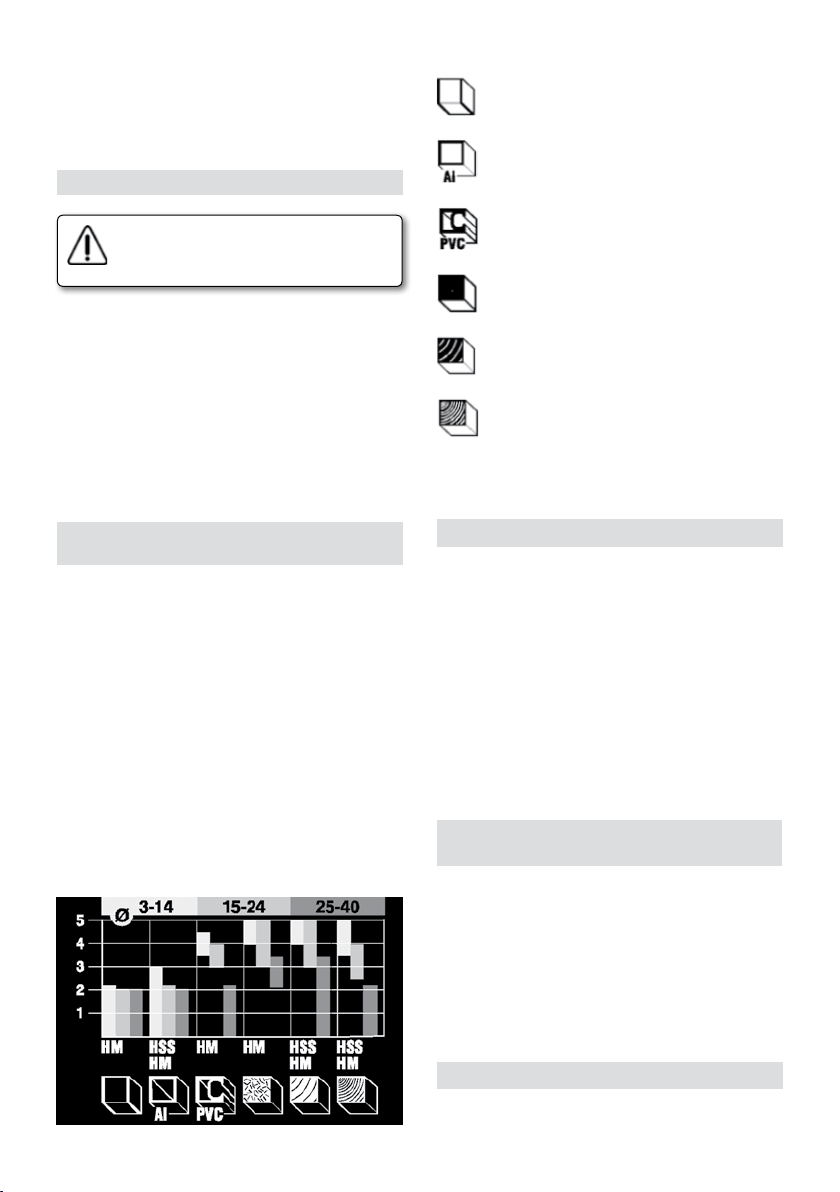
die Schraube 11 (Abb. 6) fest.
Die Feineinstellung der Fräsetiefe erfolgt durch das
Drehen vom oberen Hebel in die Richtung H (Abb. 6).
Die Genauigkeit der Einstellung soll praktisch überprüft
und ggf. nachjustiert werden.
Materialsymbole
Gypsum boards
17. ARBEITEN MIT DEM FRÄSEGERÄT
Vor der Arbeit überprüfen Sie, ob die
Netzspannung und die Spannung am
Typenschild übereinstimmen.
Einschalten / Ausschalten
Einschalten: Den Knopf der Schaltsperre 8 (Abb. 8)
drücken, dann den Hauptschalter 9 (Abb. 8) betätigen.
Dauerbetrieb: Bei eingeschaltetem Gerät weiter den
Knopf der Schaltsperre 8 drücken, um ihn zu arretieren.
Schaltsperre 8 und Hauptschalter 9 bis zum Anschlag
drücken, dann zuerst den Hauptschalter 9 loslassen und
dann noch die Schaltsperre 8.
Ausschalten: Mit einem kurzen Druck auf den Hauptschalter 9 wird das Gerät ausgeschaltet.
18. STUFENLOSE
DREHZAHLEINSTELLUNG (Typ FR278R)
Der Einstellknopf 5 (Abb. 1) ermöglicht eine stufenlose
Einstellung der Drehzahl von 6000 bis 27000 min-1.
Steuerelektronik
• Ermöglicht das Fräsen von Holz aller Art, Fräsen von
Laminaten, Kunstoffen und Aluminium.
• Gewährleistet eine gleichmässige Drehzahl unter
Belastung
• Ermöglicht die optimale Einstellung der Arbeitsdrehzahl
• Verlängert die Lebensdauer von Fräsern
• Ermöglicht einen sanften Anlauf und Überlastschutz
• Ermöglicht beim Fräsen mit grösseren Fräserdurch-
messern eine entsprechende Anpassung und bessere
Sicherheit.
Empfehlungstabelle für optimale Drehzahleinstellung
in Hinsicht auf das Bearbeitungsmaterial und den
Durchmesser der Fräser.
Aluminium
Plastics
Panel
Softwood
Hardwood
Die passende Arbeitsdrehzahl soll praktisch festgestellt
werden.
19. BEDIENUNG DER SEITENFÜHRUNG
Die Seitenführung 20 (Abb. 7) befestigen Sie mit Hilfe
zweier Führungsstäbe, die in die Bohrungen am Gerätefuss 3 (Abb. 7) eingesetzt werden. Die Führungsstäbe
werden dann mit Flügelschrauben 2 (Abb. 7) im gewünschtem Abstand befestigt.
Für genauere Abstandseinstellung benutzen Sie den
Knopf 18 und zwar so, dass Sie die Flügelschrauben
17 fixieren und Flügelschrauben 19 lösen. Durch das
Drehen am Knopf 18 (Abb. 7) können Sie die Fräse
näher oder weiter an die Führung heran bringen. Bei
jeder vollen Drehung der Mutter wird der Abstand um
1,25 mm verändert. Nach der Einstellung werden noch
die Schrauben 19 festgeschraubt.
20. VERWENDUNG DER
SCHABLONENFÙHRUNGEN
Die Schablonenführungen werden zum Fräsen vieler
verschiedener Formen verwendet. Die gewählte Schablonenführung 26 (Abb. 1) wird mit den zwei Schrauben
am Unterteil 3 (Abb. 1) befestigt.
Wenn man kopiert, gibt es einen Größenunterschied
zwischen der Schablone und dem gefrästen Teil. Berücksichtigen Sie immer den Unterschied zwischen dem Radius
der Schablonenführung und dem des Werkzeugs, wenn
Sie die Schablone herstellen.
21. RUNDFRÄSEN MIT ZIRKEL (Abb. 9)
Auf einen der beiden Führungsstäbe 27 die Zirkellasche 22
anbringen, die Nadel dann mit Flügelmutter befestigen.
20
Page 21

Den auf diese Weise zusammengesetzten Zirkel in die
Öffnung am Gerätefuss einsetzen.
Den gewünschten Abstand zwischen den Fräser und
Zirkelspitze einstellen und mit Flügelmutter fixieren.
22. DAS GERÄT HALTEN UND FÜHREN
Halten sie das Gerät während der Arbeit mit beiden
Händen fest. Den Schalter nur dann betätigen, wenn
der Fräser die Oberfläche des Werkstücks nicht berührt.
Bevor der Fräser das Werkstück berührt, muss das Gerät
eingeschaltet sein.
Drücken sie das Gerät nicht zu fest gegen das Bearbeitungsmaterial; lassen Sie es für Sie arbeiten.
Neigen Sie das Gerät nicht zuviel. Damit verhindern Sie
gleichmässiges Fräsen.
Lüftungsschlitze sauber halten.
Beim Fräsen folgende Hinweise beachten:
1. den Fräser wählen und ihn in die Spannhülse einspannen
2. gewünschte Fräsetiefe einstellen
3. das Gerät einschalten
4. Gerät eintauchen, Verriegelungshebel festziehen
5. Fräsen
6. Verriegelung lösen
7. Gerät ausschalten
Bewegungsrichtung des Gerätes (Abb. 12)
Beim Fräsen muss auf die richtige Richtung in Hinsicht
auf das Werkstück geachtet werden.
Die Fräse soll sich gegen die Drehrichtung vom Fräser
bewegen (Gegenlauf).
Verwendung von Revolveransatz
Bei grösseren Fräsetiefen ist es empfehlenswert stufenweise vorzugehen und wenig Material abzunehmen.
Mit Hilfe von Revolveransatz können Sie das Fräsen in
zwei oder drei Vorgangsstufen einteilen.
Die gewünschte Fräsetiefe auf max. Tiefe einstellen. Die
ersten zwei Fräsearbeiten beginnen Sie mit der höheren
Einstellungsstufen.
23. BÜRSTEN UND SCHLEIFRING
Es ist wichtig, die Bürsten auszuwechseln, wenn sie eine
minimale Länge von 5 mm erreicht haben.
Auswechseln der Bürsten
1. Ziehen Sie den Netzstecker.
2. Drehen Sie die Schrauben 1 (Abb. 8) aus dem Deckel
heraus.
3. Nehmen Sie vorsichtig den Elektronik-Schaltkreis 2
heraus (nur beim Modell FR278R).
4. Nehmen Sie den Bürstenhalter 4 aus der Führung
und die Bürste heraus.
5. Wechseln Sie die Bürsten und montieren Sie den
Bürstenhalter in seiner Aufnahme. Achten Sie darauf,
daß er leicht auf den Schleifring drückt.
6. Bauen Sie wie oben angegeben alles wieder zusammen.
Es ist ratsam, die Maschine nach dem Bürstenwechsel
ca. 15 Minuten lang laufen zu lassen.
Sollte der Schleifring Brandspuren oder abgesprungene Stellen aufweisen, empfehlen wir, ihn von einem
VIRUTEX-Kundendienst reparieren zu lassen.
Verwenden Sie dazu nie Schleifpapier.
24. ZUBEHÖR AUF WUNSCH
Auf Wunsch kann folgendes Extra-Zubehör geliefert
werden:
7722116 Durchmesser-Reduzierstück für 6 statt 8 mm.
7722115 Durchmesser-Reduzierstück für 6,35 mm
(1/4") statt 8 mm.
6446073 Anschluß Standardsauger 2,25 m
7722123 Führung für wellenförmige Holzverbindungen,
Zapfenabstand 26 mm.
7722161 Führung für wellenförmige Holzverbindungen,
Zapfenabstand 16 mm.
7722162 Führung für wellenförmige Holzverbindungen,
Zapfenabstand 34 mm.
7722160 Führung für die AGB-Schablone.
7722342 Führung für die AGB-Schablone.
7740117 Fräse für die AGB-Schablone.
25. GERÄUSCHPEGEL UND VIBRATIONSSTÄRKE
Die Lärm- und Vibrationswerte dieses Elektrowerkzeugs
wurden in Übereinstimmung mit der europäischen
Norm EN 60745-2-17 und EN 60745-1 gemessen und
dienen als Vergleichsgrundlage bei Maschinen für
ähnliche Anwendungen.
Der angegebene Vibrationspegel wurde für die
wesentlichen Einsatzzwecke des Werkzeugs ermittelt
und kann bei der Beurteilung der Gefahren durch
die Aussetzung unter Vibrationen als Ausgangswert
benutzt werden. Die Vibrationswerte können sich
jedoch unter anderen Einsatzbedingungen, mit anderen
Arbeitswerkzeugen oder bei einer ungenügenden
Wartung des Elektrowerkzeugs oder seiner Werkzeuge
stark vom angegebenen Wert unterscheiden und
aufgrund des Arbeitszyklus und der Einsatzweise des
Elektrowerkzeugs einen bedeutend höheren Wert
aufweisen.
Es ist daher erforderlich, Sicherheitsmaßnahmen zum
Schutz des Anwenders vor den Vibrationen festzulegen.
Dazu können die Aufrechterhaltung des einwandfreien
Zustands des Werkzeugs und der Arbeitsutensilien sowie
die Festlegung der Zeiten der Arbeitszyklen gehören (wie
Laufzeiten des Werkzeugs unter Last und im Leerlauf,
ohne tatsächlich eingesetzt zu werden, wodurch die
Gesamtzeit der Vibrationsauswirkungen bedeutend
verringert werden kann).
26. GARANTIE
Alle Elektrowerkzeuge von VIRUTEX habe eine garantie
21
Page 22
von 12 Monaten ab dem Lieferdatum. Hiervon ausgeschlossen sind alle Eingriffe oder Schäden aufgrund von
unsachgemässen Gebrauch oder natürlicher Abnutzung
des Geräts.
Wenden Sie sich im Falle einer Reparatur immer an den
zugelassenen Kundendiest von VIRUTEX.
27. RECYCLAGE DES OUTILS ÉLECTRIQUES
Ne jetez jamais un outil électrique avec le reste des déchets ménagers. Recyclez les outils, les accessoires et les
emballages dans le respect de l'environnement. Veuillez
respecter la réglementation en vigueur dans votre pays.
Applicable au sein de l'Union Européenne et dans
les pays européens dotés de centres de tri sélectif
des déchets:
Ce symbole présent sur le produit ou sur la documentation informative qui l'accompagne, indique qu'en fin
de vie, ce produit ne doit en aucun cas être éliminé avec
le reste des déchets ménagers.
Conformément à la directive européenne 2002/96/CE,
tout utilisateur peut contacter l'établissement dans
lequel il a acheté le produit, ou les autorités locales
compétentes, pour se renseigner sur la façon d’éliminer le
produit et le lieu où il doit être déposé pour être soumis
à un recyclage écologique, en toute sécurité.
VIRUTEX behält sich das Recht vor, die Produkte ohne
vorherige Ankündigung zu verändern.
ITALIANO
FRESATRICE TOUPIE FR277R
FRESATRICE TOUPIE ELETTRONICA FR278R
(FIGURE IN PAGINA 43)
Importante
Prima di utilizzare la macchina, leggere
attentamente questo MANUALE DI ISTRUZIONI e il PROSPETTO DELLE NORME
GENERALI DI SICUREZZA allegato. Non
cominciate a lavorare con la macchina
se non siete sicuri di avere compreso
integralmente il loro contenuto.
Conservare tutti e due i manuali per
eventuali consultazioni successive.
22
1. DATI TECNICI
Tipo.......................................................FR277R
Motore universale......................................50/60 Hz
Potenza........................................................1010 W
Velocità a vuoto.........................................24.000/m
Diametro pinza standard.................................8 mm
Profondità di fresatura................................0-50 mm
Diametro massimo della fresa.........................40 mm
Calibro di profondità
girevole.......Regolazione della profondità a 3 posizioni
Peso.............................................................2,9 Kg
Livello di pressione acustica continuo equivalente
ponderato A....................................................................91 dBA
Livello di potenza acustica A.......................................102 dBA
Incertezza della misura...............................................K = 3 dBA
Usare la protezione acustica!
Valori totali delle oscillazioni..................................ah: 4.4 m/s
Incertezza della misura...............................................K: 1,5 m/s
Tipo..........................................................FR278R
Motore universale......................................50/60 Hz
Potenza......................................................1300 W
Velocità a vuoto..............................6.000-27.000/m
Diametro pinza standard........................................8 mm
Profondità di fresatura................................0-50 mm
Diametro massimo della fresa........................40 mm
Calibro di profondità
girevole.....Regolazione della profondità a 3 posizioni
Peso.............................................................3 Kg
Livello di pressione acustica continuo equivalente
ponderato A....................................................................91 dBA
Livello di potenza acustica A.......................................102 dBA
Incertezza della misura...............................................K = 3 dBA
Usare la protezione acustica!
Valori totali delle oscillazioni..................................ah: 4.4 m/s
Incertezza della misura...............................................K: 1,5 m/s
2. CAMPO DI LAVORO
La fresatrice è un utensile professionale, studiato per
la fresatura di superfici in legno, plastica e alluminio. È
particolarmente adatta per fare sagome, bordi, cerchi,
scanalature, listelli, telai per quadri e incisioni di scritte.
3. ISTRUZIONI DI SICUREZZA PER
L'USO DELLA MACCHINA
• Prima di utilizzare l'utensile, leggere attentamente le
istruzioni per l'uso e le norme di sicurezza.
• Prima di qualsiasi intervento sull'utensile, disinserire
sempre la spina dalla presa di alimentazione.
• Non usare mai l'utensile con un cavo difettoso. Se
2
2
2
2
Page 23

durante il lavoro il cavo viene danneggiato, non toccarlo.
Estrarre subito la spina dalla presa di alimentazione.
• Fare attenzione che il cavo di alimentazione non entri
in contatto con le parti mobili dell'utensile.
• Durante la lavorazione, guidare il cavo dietro
all'utensile.
• In caso di lavoro all'aperto, usare una prolunga idonea protetta contro l'acqua. Usare un interruttore di
protezione (FID) con spegnimento a 30 mA.
• La dimensione minima del conduttore della prolunga
deve essere di 1,5 mm
2
. Se si utilizza un avvolgitore,
srotolare il cavo per l'intera lunghezza.
• Inserire la spina nella presa di alimentazione soltanto
ad interruttore spento.
• Utilizzare mezzi di protezione personale quali occhiali
protettivi, guanti e protezioni contro il rumore e le polveri.
• Guidare sempre la fresatrice con ambedue le mani.
• Dopo la fresatura, spegnere il motore.
• Prima di deporre l'utensile, liberare il piano di fresatura.
• Deporre sempre l'utensile su un piano orizzontale
e pulito.
• Non appoggiare altri utensili sul pezzo in lavorazione.
• Il pezzo in lavorazione deve essere pulito, senza resti
di materiale, di segatura ecc.
• Il luogo di lavoro deve essere ben illuminato; l'uso
dell'apparecchio in luoghi dove sono presenti materiali
infiammabili o gas è severamente vietato. Accendere/
spegnere l'utensile con l'interruttore, non staccando la
spina dalla presa di corrente.
• Durante la fresatura, fare attenzione alle viti, ai chiodi
e altri oggetti presenti nel pezzo in lavorazione.
• Iniziare la lavorazione quando l'utensile raggiunge la
massima velocità di rotazione.
• Fare attenzione al contraccolpo all'accensione del
modello FR277R, FR278R.
• Rendere impossibile un'accensione accidentale
dell'utensile.
• Usare sempre frese affilate e non danneggiate.
• Quando l'utensile non è in uso, tenerlo in luogo asciutto
e a riparo dalla polvere.
• Non indossare abiti larghi o gioielli che possono
incastrarsi nell'utensile. I capelli lunghi vanno portati
sotto a un adeguata cuffia di protezione. Lavorando
all'aperto, indossare scarpe antisdrucciolo.
• In caso di qualsiasi tipo di bloccaggio dell'utensile,
spegnerlo immediatamente ed estrarre la spina dalla
presa di corrente.
• Fissare il pezzo in lavorazione.
• Guidare l'utensile sul pezzo in lavorazione soltanto
quando è acceso. Spegnere l'utensile quando lo si
allontana dal pezzo.
• Usare soltanto parti di ricambio originali.
Guida parallela
Compasso
Chiave
Corredo raccolta polvere
Istruzioni per l'uso, garanzia
5. MONTAGGIO E REGOLAZIONE
Prima di qualsiasi operazione sull'utensile,
staccarlo dalla rete di alimentazione
6. ASPIRAZIONE DELLA POLVERE
Durante la fresatura, la levigatura ecc. del legno si
formano segatura e polvere, i quali mettono in pericolo
la vostra sicurezza e salute. L'aspirazione della polvere
previene l'inquinamento dell'aria, nocivo alla respirazione, e facilita l'eliminazione dei rifiuti.
7. MONTAGGIO DEL DISPOSITIVO
DI COLLEGAMENTO PER L'ASPIRAZIONE
Appoggiare il dispositivo di collegamento per l'aspirazione
15 (Fig. 2) al basamento 3 (Fig. 2) in modo che le due
guide A (Fig. 2) si trovino all'interno dell'apertura del
dispositivo di collegamento.
Con il pollice della mano destra premere l'apertura in
direzione A (Fig. 2) verso il bordo di incastro C, facendo
in modo che la sporgenza sul perimetro D si incastri al
bordo B (Fig. 2).
Il tubo dell'aspiratore può essere attaccato direttamente
al dispositivo 15 (Fig. 3) oppure può essere collegato al
dispositivo di collegamento girevole per l'aspirazione 4
(Fig. 3) con il tubo di aspirazione.
Sistemate il dispositivo girevole nell'apposito luogo sotto
al coperchio del motore.
Il dispositivo di collegamento superiore va montato
girandolo nella direzione C fino a che non si incastra
tra l'involucro e il coperchio del motore. Quindi attaccare la parte inferiore del tubo al dispositivo 15 nella
direzione D (Fig. 3).
Il dispositivo di collegamento girevole garantisce un
maggiore controllo dell'area di lavoro e il posizionamento
più favorevole del tubo di aspirazione. Il dispositivo ha
un diametro di 35 mm ed è quindi compatibile con i
tubi standard degli aspirapolvere.
Per mezzo del raccordo di aspirazione, la fresatrice
può essere collegata, tramite il nostro KIT ASPIRATORE
STANDARD Cod. 6446073 (opzionale), los nostros aspiratores AS182K, AS282K, AS382L o a qualsiasi altro
aspiratore industriale.
4. CONTENUTO DELL'IMBALLAGGIO
Fresatrice
8. RIMOZIONE DEI DISPOSITIVI DI
COLLEGAMENTO PER L'ASPIRAZIONE (Fig. 3)
Il dispositivo di collegamento per l'aspirazione superiore
23
Page 24
(Fig. 3) va tolto smontando prima il tubo dal dispositivo
15 nella direzione E, quindi premendo con il pollice della
mano sinistra sulla parte superiore del dispositivo nella
direzione F (Fig. 3).
9. DISPOSITIVO DI COLLEGAMENTO
PER L'ASPIRAZIONE INFERIORE (Fig. 2)
Togliere il tubo del dispositivo di collegamento per
l'aspirazione 4. Premere la manopola di bloccaggio D
sul perimetro del dispositivo quanto basta per allentarlo
e premere in direzione della freccia B. Quindi togliere il
dispositivo di collegamento. (Fig. 2)
nel dado (click).
Il mandarino deve essere posizionato nel
dato in modo che il dado e il mandarino
siano allineati sul davanti.
13. FISSAGGIO DEL PIANO DI FRESATURA
Il piano di fresatura va fissato all'altezza desiderata con
la manopola 24 (Fig. 5). La molla telescopica inserita in
esso farà tornare il piano nella posizione iniziale una
volta che la manopola verrà allentata.
10. SCELTA DELLA FRESA
Usare sempre frese con lo stesso diametro
del mandarino. Il numero di giri non deve
superare la velocità massima della fresa.
Non è consentito l'utilizzo di frese dal
diametro superiore a 40 mm.
Le frese al carburo (HM) sono adatte per la fresatura
di materiali duri e permettono velocità di lavorazione
più elevate.
11. POSIZIONAMENTO DELLE
FRESA
Prima di qualsiasi operazione sull'utensile,
staccarlo dalla rete di alimentazione.
La fresa va fissata con il mandarino 25 (Fig. 1) e il dado
13 (Fig. 1) nell'ordine seguente:
• Svitare di 1-2 giri il dado con il mandarino, che è
avvitato all'albero.
• Inserire la fresa facendola rientrare per un minimo
di 20 mm in profondità. Premendo la piastra di blocco
12 (Fig. 1, 4) bloccare l'albero, quindi con la chiave in
dotazione 23 (Fig. 1) avvitare il dado del mandarino
13 (Fig. 1). Un eccessivo avvitamento del dado può
danneggiare la filettatura dell'albero.
• Se non contiene la fresa, il dado del mandarino non
deve essere mai avvitato all'albero completamente. Ciò
può danneggiare il mandarino.
Per rimuovere la fresa, allentare il dado 13 (Fig. 1) di
un giro, poi continuare a svitare fino a che la fresa è
completamente libera.
14. REGOLAZIONE BASE DELLA
PROFONDITÀ DI FRESATURA
Prima di qualsiasi operazione sull'utensile,
staccarlo dalla rete di alimentazione.
La profondità della fresatura va regolata con le viti
sul dispositivo a revolver 16 (Fig. 6), unite al paletto di
fermo 10 (Fig. 6) e all'indicatore 28 (Fig. 6). Le tre viti
sul dispositivo a revolver permettono di scegliere tra
le tre profondità preimpostate. La profondità massima
è di 50 mm.
Posizionare la fresatrice sul pezzo in lavorazione.
Allentare la leva di blocco 24 (Fig. 5) e premere lentamente
l'utensile verso il basso. Quando tocca la superficie del
materiale, stringere la leva di blocco 24 (Fig. 5).
Girare il dispositivo a revolver 16 (Fig. 6) per impostare
la profondità di fresatura desiderata.
Svitare la vite ad alette 11 (Fig. 6) permettendo al paletto
di fermo 10 di essere mosso.
Premere il paletto di fermo 10 (Fig. 6) verso il basso, in
modo che esso si adagi sulla vite del dispositivo a revolver.
Posizionare l'indicatore di profondità 28 (Fig. 6) a 0.
Premere il paletto di fermo 10 (Fig. 6) verso l'alto. Quando
la profondità desiderata è raggiunta sull'indicatore 7
(Fig. 6), avvitare la vite ad alette 11 (Fig. 6).
Allentare la leva di blocco 24 (Fig. 5), impostare poi la
fresa in un'altra posizione preregolata fino a che il paletto
di fermo 10 (Fig. 6) non si incastra sulla vite e stringere
nuovamente la leva di blocco 24 (Fig. 5).
La regolazione base va sperimentata in pratica e modificata in base alle osservazioni.
15. REGOLAZIONE FINE DELLA
PROFONDITÀ DI FRESATURA
12. SOSTITUZIONE DEL MANDARINO
Il mandarino è fissato nel dado 13 (Fig. 10). Quando si
vuole cambiarlo, bisogna estrarlo dal dado con un piccolo
cacciavite che va inserito tra il dado e il mandarino. Il
nuovo mandarino viene inserito premendolo con forza
24
Prima di qualsiasi operazione sull'utensile,
staccarlo dalla rete di alimentazione.
La regolazione fine della profondità di fresatura va
Page 25
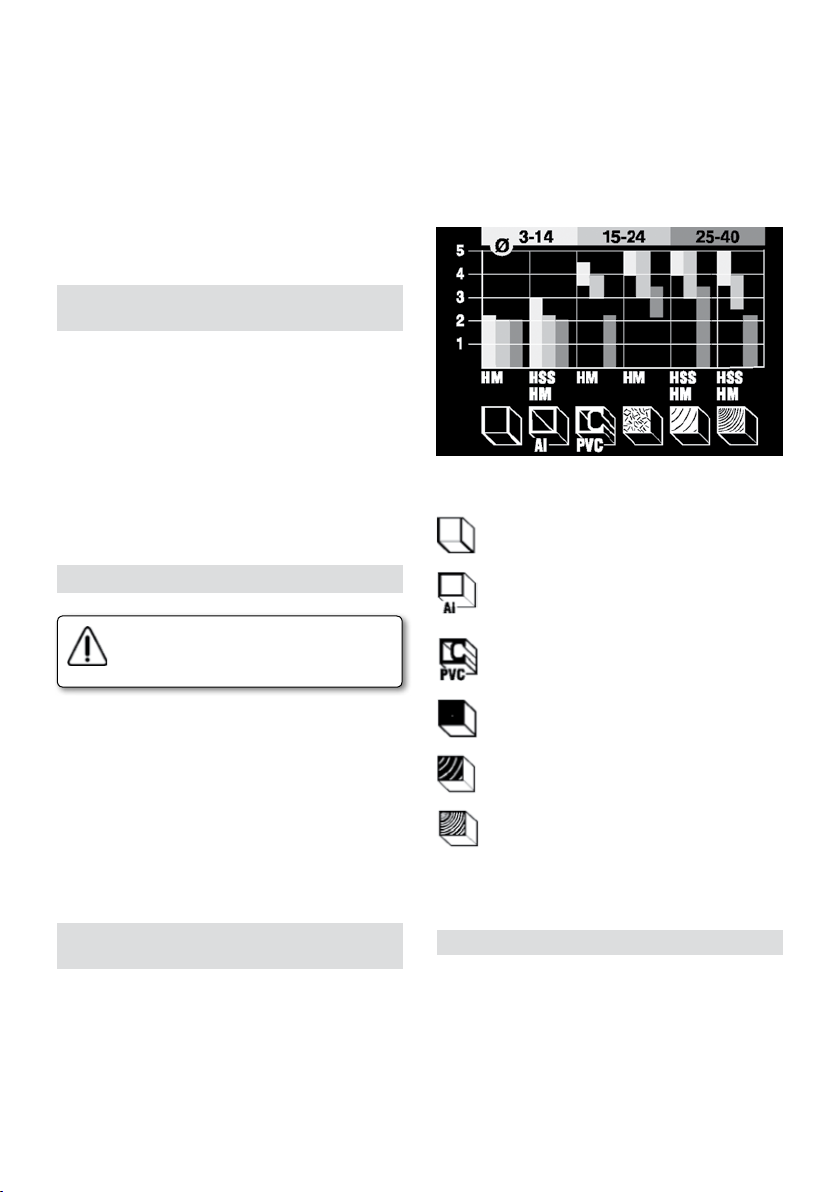
effettuata se necessaria. Dopo la regolazione base si può
regolare la profondità desiderata girando la manopola
del paletto di fermo con una precisione di 0,1 mm (una
lineetta = 0,1 mm).
Allentare la leva di blocco 24 (Fig. 5). Mentre si preme
l'utensile verso il basso, premere il pulsante superiore del
paletto di fermo nella direzione G (Fig. 6), in modo che
si incastri alla vite del dispositivo a revolver 16 (Fig. 6).
Allineare il pulsante inferiore a quello superiore, quindi
girare il pulsante superiore nella direzione H nella misura
desiderata. Stringere di nuovo la leva di blocco 24 (Fig. 5).
16. REGOLAZIONE FINE CON LA
FRESATRICE FISSATA AL PIANO DI LAVORO
Appoggiare il paletto di fermo 10 (Fig. 6) alla vite del
dispositivo a revolver con la colonna filettata e la molla.
Avvitare la colonna filettata 14 (Fig. 6) al paletto di fermo
10. Fare attenzione che il cacciavite che si trova all'interno
del paletto di fermo si incastri nella filettatura della vite
sotto al dado 14. Premendo sul coperchio dell'utensile,
regolare la profondità approssimativa e stringere la vite
11 (Fig. 6). La regolazione fine va effettuata girando la
manopola superiore nella direzione H (Fig. 6).
La precisione della regolazione va controllata con una
prova pratica e va quindi modificata adeguatamente.
17. COME SI USA LA FRESATRICE
Prima di utilizzare l'utensile, verificare che
la tensione indicata sulla targhetta sia
conforme alla tensione della rete.
• Allunga la vita delle frese.
• Permette un avviamento morbido dell'utensile e lo
protegge dal sovraccarico.
• Durante la fresatura di diametri più larghi, permette
un maggiore adeguamento e offre maggiore sicurezza.
Tabella dei valori consigliati nella scelta della regolazione
in rapporto al materiale in lavorazione e al diametro
della fresa.
Simboli dei materiali
Pannelli in gesso
Alluminio
Plastica
Accensione / spegnimento
Accensione: premere il pulsante del bloccaggio di
antiaccensione 8 (Fig. 8), quindi manovrare la levetta
dell'interruttore 9 (Fig. 8).
Lavorazione prolungata: premendo il pulsante 8 ad
interruttore acceso, questo viene bloccato. Premere
il pulsante 8 e la manopola 9 completamente, quindi
lasciare andare prima la manopola 9 e poi il pulsante 8.
Spegnimento: premendo nuovamente la manopola
dell'interruttore 9 l'utensile si spegne.
18. REGOLAZIONE DELLA VELOCITÀ DI
ROTAZIONE SCORREVOLE (TIPO FR278R)
Usando il pulsante di regolazione 5 (Fig. 1) si può ottenere un passaggio scorrevole tra i 6000 e i 27000 min-1.
La regolazione elettronica
• Permette la fresatura di tutti i tipi di legno, laminati,
materiali artificiali e alluminio.
• Permette che la velocità di rotazione preimpostata
rimanga costante durante la lavorazione.
• Permette la scelta della velocità di rotazione ottimale.
Pannelli compensati
Legno dolce
Legno duro
Trovare la velocità di rotazione adatta con una prova
pratica.
19. UTILIZZO DELLA GUIDA PARALLELA
La guida parallela 20 (Fig. 7) va fissata inserendo le due
barre guida nei fori sul basamento 3 (Fig. 7) e avvitandole
alla distanza desiderata con le viti ad alette 2 (Fig. 7).
Per una regolazione più precisa, usare la manopola 18,
fissando le viti ad alette 17 e allentando le viti ad alette
19. Girando la manopola 18 (Fig. 7), la fresatrice si avvicina o si allontana dalla guida. Per ogni giro completo
del dado, la distanza si modifica di 1,25 mm. Dopo la
regolazione, stringere le viti 19 (Fig. 7).
25
Page 26

20. UTILIZZAZIONE DEL PALPATORE DI SAGOMA
I palpatori di sagoma sono utilizzati per la fresatura di
una gran varietà di forme. La guida sagoma prescelta 26
(Fig. 1) va fissata alla base 3 (Fig. 1) per mezzo della due
viti. Quando si esegue una copiatura, c'è una differenza
di dimensione tra la guida e il pezzo fresato. Quando si
prepara la sagoma, bisogna tenere sempre in considerazione la differenza esistente tra il raggio della guida
sagoma 13 (Fig. 11) e quello dell'utensile.
21. FRESATURA CIRCOLARE
CON IL COMPASSO (Fig. 9)
Sistemare su una delle barre di guida 27 lo snodo del
compasso 22, e fissare la punta con una vite ad alette.
Quindi porre il tutto in una delle fessure del basamento
della fresatrice. Regolare la distanza desiderata tra la fresa
e la punta del compasso e fissarla con la vite ad alette.
22. IMPUGNATURA E GUIDA DELL'UTENSILE
Durante la lavorazione, impugnare sempre l'utensile
con ambedue le mani. Accendere l'interruttore solo
quando la fresa non è in contatto con la superficie del
pezzo in lavorazione.
Prima che la fresa tocchi il pezzo in lavorazione,
l'apparecchio deve essere in funzione.
Non premere l'utensile durante la lavorazione, lasciare
che esso lavori per voi.
Non inclinare l'utensile, in tal modo si eviterà
un'irregolare esportazione di materiale.
Evitare di coprire le feritoie di ventilazione.
Durante la lavorazione con la fresatrice, rispettare
il seguente ordine:
1. scegliere la fresa e inserirla nel mandarino,
2. regolare la profondità desiderata,
3. azionare l'utensile,
4. premere il motore verso il basso, stringere la leva
di blocco,
5. fresare,
6. allentare la leva di blocco,
7. spegnere l'utensile.
Direzione dell'avanzamento dell'utensile (Fig. 12)
Durante la fresatura fare attenzione che la direzione
d'avanzamento sia corretta in relazione al pezzo in
lavorazione.
Far avanzare la fresatrice in senso contrario a quello
della fresa.
Utilizzo del dispositivo a revolver per la profondità
Per profondità di fresatura più elevate è opportuna una
fresatura graduale, con piccole asportazioni di mate-
riale. Usando il dispositivo a revolver si può dividere la
fresatura in due o tre fasi.
Regolare la profondità desiderata usandola come profondità maggiore di fresatura 16 (Fig. 1). I primi due
gradi vanno posizionati più verso l'alto.
26
23. SPAZZOLE E COLLETTORE
È molto importante sostituire le spazzole quando la loro
lunghezza minima è di 5 mm.
Sostituzione delle spazzole.
1. Staccare la macchina dalla rete elettrica.
2. Togliere le viti del coperchio.
3. Estrarre con precauzione il circuito elettronico 2 (solo
nel modello FR278R).
4. Estrarre il portaspazzole 4 dalla guida e togliere la spazzola.
5. Sosriruire le spazzole e montare il portaspazzole nella sua
sede, controllando che poggi delicatamente sul collettore.
6. Rimontare come precedentemente indicato. Dopo la
sostituizone delle spazzole, è consigliabile lasciare la
macchina in moto per una quindicina di muniti.
Se il collettore presenta bruciature o rigonfiamenti,
si raccomanda di farlo rettificare presso un servizio di
assistenza tecnica VIRUTEX.
Non usare mai carta smerigliata per eseguire questa operazione.
24. ACCESSORI OPZIONALI
Sono disponibili i seguenti accessori opzionali:
7722116 Riduttore di Ø da 8 a 6 mm
7722115 Riduttore di Ø da 8 a 6,35 mm (1/4")
6446073 Kit aspiratore standard 2,25 m
7722123 Guida per coda di rondine da 26 mm
7722161 Guida per coda di rondine da 16 mm
7722162 Guida per coda di rondine da 34 mm
7722160 Guida per sagoma AGB.
7722342 Guida per sagoma AGB.
7740117 Fresa per sagoma AGB.
25. LIVELLI DI RUMORE E DI VIBRAZIONI
I livelli di rumore e vibrazioni di questo apparato elettrico sono stati misurati in conformità con la Norma
Europea EN 60745-2-17 e EN 60745-1 e fungono da
base di confronto con macchine per applicazioni simili.
Il livello di vibrazioni indicato è stato determinato per
le principali applicazioni dell’apparato e può essere
utilizzato come punto di partenza per la valutazione
dell’esposizione al rischio delle vibrazioni. Ciononostante,
il livello di vibrazioni può variare notevolmente rispetto
al valore dichiarato in altre condizioni di applicazione,
con altri strumenti di lavoro o in caso di manutenzione
insufficiente dell’apparato elettrico e dei suoi strumenti,
e può aumentare notevolmente come conseguenza del
ciclo di lavoro e del modo d’uso dell’apparato elettrico.
Pertanto è necessario stabilire misure di sicurezza per
la protezione dell’utente dall’effetto delle vibrazioni,
ad esempio mantenendo l’apparato e gli strumenti
di lavoro in perfetto stato e pianificando i tempi dei
cicli lavorativi (ad esempio i tempi di funzionamento
dell’apparato sotto carico e i tempi di funzionamento
a vuoto quando l'apparato non viene realmente utilizzato, dato che la riduzione di questi ultimi può ridurre
in modo sostanziale il valore totale dell’esposizione).
Page 27

26. GARANZIA
Tutte le macchine elettroportatili VIRUTEX hanno una
garanzia di 12 mesi valida a partire della data di consegna, con l'esclusione di tutte le manipolazioni o danni
derivanti da un uso inadeguato o dall'usura normale
della macchina.
Per qualunque riparazione rivolgersi al servizio autorizzato di assistenza tecnica VIRUTEX.
27. SMALTIMENTO DI APPARECCHI ELETTRICI
Non buttare mai gli apparecchi elettrici con il resto dei
rifiuti domestici. Smaltire gli apparecchi, gli accessori
e gli imballaggi nel rispetto dell'ambiente. Rispettare la
normativa vigente nazionale.
Applicabile nell’Unione Europea e nei paesi europei
con sistemi di raccolta differenziata dei rifiuti:
La presenza di questo marchio sul prodotto o sul materiale
informativo che lo accompagna indica che, al termine
della sua vita utile, non dovrà essere eliminato insieme
ad altri rifiuti domestici.
Conformemente alla Direttiva Europea 2002/96/CE,
gli utenti possono contattare il punto vendita presso
cui è stato acquistato il prodotto, o le autorità locali
pertinenti, per informarsi su come e dove portarlo per
il suo smaltimento ecologico e sicuro.
La VIRUTEX si riserva il diritto di modificare i propi
prodotti senza preaviso.
PORTUGUÉS
FRESADORA TUPIA FR277R
FRESADORA TUPIA ELECTRÓNICA FR278R
(FIGURAS EM PAGINA 43)
Importante
Antes de utilizar a máquina leia atentamente este MANUAL DE INSTRUÇÕES e
o FOLHETO DE INSTRUÇÕES GERAIS DE
SEGURANÇA anexo. Assegure-se de os
ter compreendido antes de começar a
trabalhar com a máquina.
Conserve os dois manuais de instruções
para possíveis consultas posteriores.
1. DADOS TECNICOS
Tipo..........................................................FR277R
Motor universal..........................................50/60 Hz
Potência........................................................1010 W
Velocidade sem carga..............................24.000/m
Diâmetro da pinça standard..............................8 mm
Profundidade de fresagem..........................0-50 mm
Diâmetro máximo da fresa..............................40 mm
Galga de profundidade
giratória...........ajuste de profundidade de 3 posições
Peso.............................................................2,9 Kg
Nível de pressão acústica contínuo
equivalente ponderado A...............................................91 dBA
Nível de potência acústica A.........................................102 dBA
Incerteza.........................................................................K = 3 dBA
Usar protecção auricular!
Valores totais de vibração.....................................ah: 4.4 m/s
Incerteza........................................................................K: 1,5 m/s
Tipo..........................................................FR278R
Motor universal.........................................50/60 Hz
Potência........................................................1300 W
Velocidade sem carga....................6.000-27.000/m
Diâmetro da pinça standard.............................8 mm
Profundidade de fresagem........................0-50 mm
Diâmetro máximo da fresa.............................40 mm
Galga de profundidade
giratória..........ajuste de profundidade de 3 posições
Peso....................................................................3 Kg
Nível de pressão acústica contínuo
equivalente ponderado A...............................................91 dBA
Nível de potência acústica A.........................................102 dBA
Incerteza.........................................................................K = 3 dBA
Usar protecção auricular!
Valores totais de vibração.....................................ah: 4.4 m/s
Incerteza........................................................................K: 1,5 m/s
2. GAMA DE TRABALHO
A fresadora de madeira ou tupi é uma ferramenta profissional desenhada para lavrar desenhos em madeira,
plástico e alumínio. É uma excelente ferramenta para
lavrar bastidores, realizar contornos, círculos, entalhes,
para elaborar acabamentos em molduras ou realizar
inscrições.
3. INSTRUÇÕES DE SEGURANÇA
PARA O MANEJO DA MÁQUINA
Leia as instruções de uso e de segurança detidamente
antes de utilizar a ferramenta.
• Desconecte o plugue antes de realizar qualquer ajuste
27
2
2
2
2
Page 28

na máquina.
• Não utilize a ferramenta se o cabo estiver danificado.
Se o cabo se danifica durante o trabalho, não o toque,
desconecte-o da tomada imediatamente.
• Mantenha sempre o cabo longe das partes móveis
da ferramenta. Dirija o cabo para a parte traseira da
ferramenta.
• Use somente um cabo de extensão apropriado para uso
exterior e equipado com uma tomada à prova d'água.
Conecte a ferramenta a uma fonte equipada com um
interruptor-protetor de falha de corrente (FI) com uma
corrente de acionamento de 30 mA máximo.
• A seção dos cabos deve ter uma seção mínima de 1,5
2
mm
e o cabo deve estar completamente desenrolado.
• Conecte o plugue unicamente se o interruptor estiver
em posição de apagado.
• Utilize sempre equipamento de proteção pessoal:
protetores auditivos, óculos e botas de trabalho.
• Sujeite sempre a máquina com ambas mãos.
• Apague o motor depois de terminar o trabalho.
• Antes de deixar a máquina libere a base deslizante.
• Ponha sempre a máquina em uma superfície hori-
zontal limpa.
• Não coloque nenhuma outra ferramenta sobre a
superfície de trabalho.
• A peça de trabalho deve estar limpa, livre de pó,
lascas, aparas, etc.
• O lugar de trabalho deve ter uma iluminação adequada.
É proibido utilizar a ferramenta em habitações com
substâncias inflamáveis ou gases. Ligue ou desligue a
ferramenta utilizando o interruptor e não desconectando o plugue.
• Tenha cuidado com parafusos, pregos ou outros objetos
que possam estar na superfície de trabalho.
• Comece a trabalhar somente quando a ferramenta
tiver alcançado a sua velocidade máxima.
• Cuidado com um movimento forte ao ligar a FR277R,
FR278R.
• Previna qualquer acionamiento acidental do interruptor.
• Utilize somente freses em bom estado e corretamente
afiadas.
• Quando não estiver utilizando a ferramenta, guarde-a
em um lugar fresco e limpo, livre de umidade.
• Não utilize roupa frouxa ou jóias que possam ficar
presas à máquina. Se você tem cabelo comprido, use
uma rede protetora. Ao trabalhar em exteriores, utilize
calçado antideslizante.
• Em caso de bloqueio da ferramenta, desligue imedia-
tamente o interruptor e desconecte o plugue da tomada.
• Assegure firmemente a peça de trabalho.
• Somente guie a ferramenta sobre a peça de trabalho.
Desligue o interruptor depois de retirar a máquina da
superfície de trabalho.
• Utilize unicamente acessórios e peças originais.
28
4. CONTEÚDO DO PACOTE
Fresadora
Guia lateral
Compasso
Chave de boca
Adaptador para extração de pó
Instruções de uso, garantia
5. PREPARANDO-SE PARA O TRABALHO
Sempre desconecte o plugue da tomada
antes de realizar ajustes ou trocar os
acessórios.
6. ASPIRAÇÃO DE PÓ
Trabalhar com madeira gera pó, lascas e aparas que
compromentem a segurança e a saúde. Aspirar o pó
evita a contaminação do ar e facilita a eliminação de
desperdícios.
7. MONTAGEM DO ADAPTADOR DE PÓ
Coloque o adaptador inferior de pó 15 (Fig. 2) na base
3 (Fig. 2) de modo que as guias A (Fig. 2) fiquem dentro
do bocal do adaptador.
Pressione o bocal com o polegar direito na direção A (Fig.
2) do fechamento limite C de modo que o seguro no
perímetro se sujeite automaticamente à borda B (Fig. 2).
Conecte o tubo do aspirador diretamente ao adaptador
de pó 15 (Fig. 3), ou conecte-o com uma mangueira
equipada com um tubo articulado para extrair o pó 4
(Fig. 3). Fixe-o debaixo da tampa do motor.
Monte o adaptador superior de extração pressionando
na direção C até que ele se acople entre a caixa de en-
grenagens e a tampa do motor. A seguir, conecte a parte
inferior do tubo ao adaptador 15 na direção D (Fig. 3).
A conexão articulada permite uma melhor vista da área
a ser trabalhada e também coloca a aspiradora em uma
posição mais favorável. O diâmetro do adaptador de pó
é de 35 mm, correspondendo ao padrão das mangueiras
das aspiradoras no mercado.
Através do conector de aspiração, a fresadora pode
ser ligada, por meio do ACOPLAMENTO ASPIRAÇÃO
STANDARD Refª 6446073 (optativo), ao nossos aspiradores AS182K, AS282K, AS382L ou a qualquer outro
aspirador industrial.
8. RETIRANDO O ADAPTADOR SUPERIOR
DE EXTRAÇÃO DE PÓ (Fig. 3)
O adaptador superior (Fig. 3) com o tubo pode ser removido primeiramente retirando a mangueira do adaptador
inferior 15 na direção E e, a seguir, empurrando com
o polegar esquerdo a parte superior do extrator de pó
Page 29

na direção F (Fig. 3).
9.RETIRANDO O ADAPTADOR INFERIOR
DE EXTRAÇÃO DE PÓ (Fig. 2)
Retire a mangueira do adaptador de extração de pó 4.
Pressione o seguro D na parte externa do adaptador
15 o suficiente para liberá-lo e empurre na direção da
flecha B. A seguir, retire o adaptador. (Fig. 2)
10. ESCOLHENDO A FRESE
Sempre use freses cujos veios correspondam ao diâmetro da pinça. A velocidade de
trabalho não deve exceder as revoluções
permitidas pela frese. Está proibido utilizar freses de diâmetro maior a 40 mm.
As freses dotadas de dentes de carbureto (HM) são
adequadas para trabalhar em materiais mais duros e
em maiores velocidades.
11. COLOCANDO AS FRESES
Sempre desconecte o plugue da tomada
antes de realizar ajustes ou trocas de
acessórios.
Fixe a frese com a pinça 25 (Fig. 1) e a porca 13 (Fig. 1).
A ordem correta para ajustar é:
• Afrouxe a porca que sujeita a pinça na árvore em 1
ou 2 voltas.
• Insira uma frese. A frese deve penetrar ao menos 20
mm dentro da pinça. Pressionando o botão de bloqueio
12 (Fig. 1, 4) se imobiliza a árvore e é possível ajustar
a porca 13 (Fig. 1) utilizando a chave de boca 23 (Fig.
1). O ajuste excessivo da porca pode danificar o fio da
rosca da árvore.
• Nunca ajuste até o tope a porca se a frese não estiver
colocada na pinça. Perigo de danificar a pinça!
Para remover a frese em uma só volta bloqueie a ár-
vore e afrouxe primeiro a porca 13 (Fig. 1), e continue
afrouxando-a até que a frese esteja totalmente livre.
12. TROCA DE PINÇA
A pinça deve estar fixa na porca de ajuste 13 (Fig. 10).
Quando você quiser trocá-la, puxe-a utilizando uma
chave de fenda pequena, a qual deve inseri-la entre
a porca e a pinça. Insira a nova pinça empurrando-a
fortemente dentro da porca (click).
Atenção: A pinça deve ser inserida na porca, de modo
que se alinhem no lado frontal.
13. AJUSTE DA BASE
Ajuste a base da máquina na altura desejada por meio da
alavanca 24 (Fig. 5). Resortes internos fazem com que a
base volte à posição original quando se libera a alavanca.
14. AJUSTE VASTO DE PROFUNDIDADE
Sempre desconecte o plugue da tomada
antes de realizar ajustes ou trocas de
acessórios.
Calibre a profundidade de fresado mediante os parafusos
do tope-revólver 16 (Fig. 6), junto com a cavilha de ajuste
10 (Fig. 6) no indicador 28 (Fig. 6). Os três parafusos
no tope-revólver permitem realizar um pré-ajuste de
3 profundidades diferentes. A escala total é de 50 mm.
Coloque a máquina sobre a superfície de trabalho.
Libere a alavanca 24 (Fig. 5) e lentamente pressione a
ferramenta para baixo. Quando a frese tocar a superfície,
puxe a alavanca 24 (Fig. 5).
Gire o tope-revólver 16 (Fig. 6) até o parafuso de altura
mais favorável.
Afrouxe o parafuso borboleta 11 (Fig. 6) para permitir
o movimento da cavilha de ajuste 10.
Empurre a cavilha de ajuste para baixo 10 (Fig. 6) até
que ela encoste na cabeça do parafuso do tope-revólver.
Calibre a regleta de profundidade 28 (Fig. 6) a 0.
Empurre a cavilha de ajuste 10 (Fig. 6) para cima. Ao
alcançar a profundidade desejada na escala 7 (Fig. 6),
ajuste o parafuso borboleta 11 (Fig. 6).
Libere a alavanca 24 (Fig. 5) e empurre a cavilha até a
nova posição pré-establecida de maneira que a cavilha
de ajuste 10 (Fig. 6) descanse sobre o parafuso, e depois
puxe a alavanca 24 (Fig. 5) novamente.
Verifique o ajuste vasto através de uma prova prática e
corrija-o caso seja necessário.
15. AJUSTE FINO DA PROFUNDIDADE
DE FRESADO
Sempre desconecte o plugue da tomada
antes de realizar ajustes ou trocas de
acessórios.
Realize uma calibração fina caso seja necessário. Depois de configurar o ajuste vasto, você pode calibrar a
profundidade de fresado até com 0,1 mm de precisão
girando o botão da cavilha de ajuste (1 linha = 0,1 mm).
Primeiro libere a alavanca 24 (Fig. 5). Enquanto você
pressiona a ferramenta para baixo, pressione o botão
superior da cavilha de ajuste na direção G (Fig. 6), de
maneira que esta descanse sobre a cabeça do parafuso
29
Page 30

do tope-revólver 16 (Fig. 6). Ajuste o botão inferior com
o superior e logo gire o botão superior na direção H ao
valor desejado. Puxe novamente a alavanca 24 (Fig. 5).
16. AJUSTE FINO DA PROFUNDIDADE DE FRESADO QUANDO A FRESADORA ESTÁ FIXA EM
UMA MESA
Mantenha a cavilha 10 (Fig. 6) sobre o jogo de parafuso
e mola do tope-revólver.
Ajuste o parafuso com agulheiro 14 (Fig. 6) contra a
cavilha de ajuste 10. Preste atenção ao pôr a chave de
fenda no interior da ranhura do parafuso com agulheiro
14. Pressionando a tampa da ferramenta, você pode fixar
a profundidade aproximada de corte e ajustar o parafuso
11 (Fig. 6). Calibre finamente girando a alavanca superior
em sentido H (Fig. 6).
Verifique a precisão através de uma prova prática e
corrija-a caso seja necessário.
Simbologia de materiais
Tabuleiros de gesso, alvenaria leviana
17. TRABALHANDO COM A FRESADORA
Verifique sempre que a voltagem disponível seja a mesma voltagem indicada na
placa técnica da máquina.
Ligar e desligar on / off
Ligar: Pressione o botão de desbloqueio 8 (Fig. 8), e logo
pressione a alavanca do interruptor 9 (Fig. 8).
Operação Contínua: Quando a ferramenta estiver ligada
pressione mais o botão 8 e bloqueie o interruptor. Pressione o botão 8 e a alavanca 9 até o final, logo libere a
alavanca 9 e o botão 8.
Desligar: Pressionando novamente a alavanca 9 ,você
pode apagar a máquina.
18. VELOCIDADE VARIÁVEL DE
ONDA COMPLETA (TIPO FR278R)
Girando o botão 5 (Fig. 1) pode variar-se a velocidade
desde 6000 até 27000 rpm.
Eletrônica constante
• Permite trabalhar em todo tipo de madeiras, laminados,
plásticos e alumínio
• Permite manter a velocidade do motor constante
mesmo com cargas elevadas
• Permite selecionar a melhor velocidade de trabalho
• Alarga a vida útil da ferramenta
• Oferece um arranque suave e uma proteção contra
as sobrecargas
• Permite un ajuste adequado e oferece maior segurança
ao trabalhar com fresas de diâmetros grandes
Tabela recomendada para selecionar a velocidade de
acordo ao material de trabalho e diâmetro de frese
30
Alumínio
Plásticos
Painéis aglomerados
Madeiras suaves
Madeiras duras
Encontre a velocidade adequada para seu material de
trabalho através de uma prova prática.
19. USO DA GUIA LATERAL
Coloque a guia lateral 20 (Fig. 7) inserindo os eixos nos
agulheiros da base 3 (Fig. 7), e ajustando-os na distância
desejada através dos parafusos borboleta 2 (Fig. 7).
Utilize o botão 18 para um ajuste mais exato, aperte os
dois parafusos 17 e afrouxe os parafusos 19. Girando
o botão 18 (Fig. 7), você pode mover as guias. Ao girar
completamente a porca, a distância deslocada é de 1,25
mm. Aperte os parafusos 19 (Fig. 7) depois do ajuste.
20. UTILIZAÇÃO DOS APALPADORES DE MOLDE
Os apalpadores de molde são utilizados para fresar uma
grande variedade de formas. A guia molde escolhida
26 (Fig. 1) agarra-se à base 3 (Fig. 1) por meio dos dois
parafusos.
Ao realizar uma cópia aparece uma diferença de tamanho
entre o molde e a peça fresada.
Page 31

Ao confeccionar o molde, há que ter sempre em linha
de conta a diferença entre o raio da guia molde 13 (Fig.
11) e o da ferramenta.
21. FRESADO CIRCULAR COM COMPASSO (Fig. 9)
Fixe o compasso 22 a uma das columnas 27 ajustandoo com a porca borboleta. Insira a coluna em um dos
agulheiros da base da máquina. Selecione a distância
desejada entre a fresadora e o ponto de giro. Ajuste-o
com uma porca borboleta 2 (Fig. 9).
22. SUJEITANDO E GUIANDO A FERRAMENTA
Sujeite a ferramenta com ambas mãos enquanto trabalha. Antes que a fresadora toque a peça de trabalho,
ela deve estar ligada. Nunca a ligue quando ela estiver
tocando a peça de trabalho.
Não aplique pressão sobre a ferramenta enquanto trabalha, deixa que ela faça o trabalho por você.
Não incline a ferramenta para evitar um fresado irregular.
Mantenha limpas e descobertas as redes de ventilação
do motor.
Ao trabalhar com a fresadora siga a seguinte ordem:
1. Escolha uma frese e fixe-a na pinça
2. Selecione a profundidade desejada
3. Ligue a ferramenta
4. Pressione o motor para baixo, puxe a alavanca de
bloqueio
5. Realize o fresado
6. Libere o bloqueio
7. Apague a ferramenta
Direção de deslocamento da máquina (Fig. 12)
Ao fresar, você deve ter cuidado com a direção correta de
deslocamento da máquina em relação à peça de trabalho.
Mova a máquina em sentido oposto ao giro da frese
(protitek).
Uso do tope-revólver
Ao fresar em grandes profundidades, lhe recomendamos
fazê-lo em fases ao longo do material. Utilizando o
tope revólver, você pode realizar o fresado em 2 ou 3
fases ou passes.
Selecione a profundidade de fresado na profundidade
máxima desejada 16 (Fig. 1). A seguir, realize fresados
intermediários utilizando passes a menor profundidade.
23. ESCOVAS E COLECTOR
Torna-se importante substituir as escovas quando estas
tiverem um comprimento mínimo de 5 mm.
Substituição das escovas
1. Desligar a máquina da corrente eléctrica.
2. Retirar os parafusos da tampa.
3. Com precaução, retirar o circuito electrónico (só no
modelo FR278R).
4. Extrair o porta-escovas 4 da guia e a escova.
5. Substituir as escovas e montar o porta-escovas no
seu alojamento, verificando que pressione suavemente
no colector.
6. Voltar a montar, tal e como foi indicado anteriormente.
Depois de susbstituídas as escovas, é aconselhável ter a
máquina em funcionamento durante uns 15 minutos.
Se o colector apresentar queimaduras ou saliências. é
recomendável proceder à sua reparação num Serviço
Técnico VIRUTEX.
Para esta operação, não utilizar jamais papel de lixa.
24. ACESSÓRIOS OPTATIVOS
Podem ser fornecidos os seguintes acessórios optativos:
7722116 Reductor de Ø 8 a 6 mm.
7722115 Reductor de Ø 8 a 6,35 mm. (1/4").
6446073 Acoplamento aspiração standard 2,25 m.
7722123 Guia para laço passagem 26 mm.
7722161 Guia para laço passagem 16 mm.
7722162 Guia para laço passagem 34 mm.
7722160 Guia para molde AGB.
7722342 Guia para molde AGB.
7740117 Fresa para molde AGB.
25. NIVEL DE RUIDO E VIBRAÇÕES
Os níveis de ruído e vibrações desta ferramenta eléctrica foram medidos de acordo com a Norma Europeia
EN 60745-2-17 e EN 60745-1 e servem como base de
comparação com uma máquina de aplicação semelhante.
O nível de vibrações indicado foi determinado para as
principais aplicações da ferramenta e pode ser utilizado
como valor de partida para a avaliação da exposição ao
risco das vibrações. Contudo, o nível de vibrações pode
alcançar valores muito diferentes do valor indicado
noutras condições de aplicação, com outros dispositivos
de trabalho ou com uma manutenção deficiente da
ferramenta eléctrica e respectivos dispositivos, podendo
resultar num valor muito mais elevado devido ao seu
ciclo de trabalho e modo de utilização.
Por conseguinte, é necessário estabelecer medidas de
segurança para protecção do utilizador contra o efeito
das vibrações, tais como a manutenção da ferramenta,
conservação dos respectivos dispositivos em perfeito
estado e organização dos períodos de trabalho (tais
como os períodos de trabalho com a ferramenta em
carga e períodos de trabalho com a ferramenta em vazio
e sem ser realmente utilizada, uma vez que a redução
da carga pode diminuir de forma substancial o valor
total da exposição).
26. GARANTIA
Todas as máquinas electro-portáteis VIRUTEX possuem
uma garantia válida por 12 meses contados a partir
do dia do seu fornecimiento, ficando dela excluídas
todas aquelas manipulações ou danos ocasionados por
utilizações não adequadas ou pelo desgaste natural da
31
Page 32
máquina. Para qualquer reparação, há que se dirigir ao
Serviço Oficial de Assistência Técnica VIRUTEX.
27. RECICLAGEM DAS FERRAMENTAS ELÉTRICAS
Nunca elimine a ferramenta elétrica com os restantes
resíduos domésticos. Recicle as ferramentas, os acessórios
e as embalagens de uma forma que respeite o meio
ambiente. Respeite os regulamentos em vigor no seu país.
Aplicável na União Europeia e nos países europeus
com sistemas de recolha seletiva de resíduos:
A presença deste símbolo no produto ou no material
informativo que o acompanha indica que, no final da
sua vida útil, não se deve proceder à sua eliminação em
conjunto com outros resíduos domésticos.
Nos termos da Diretiva Europeia 2002/96/CE, os utilizado-
res podem contactar o estabelecimento onde adquiriram
o produto, ou as autoridades locais competentes, para
obter informações sobre como e onde poderão levar o
produto para que este seja submetido a uma reciclagem
ecológica e segura.
A VIRUTEX reserva para si o direito de poder modificar
os seus productos, sin a necessidade de aviso prévio.
Универсальный двигатель.....................50/60 Гц
Мощность.................................................1010 Вт
Холостой ход.......................24.000 оборотов/мин
Диаметр стандартной цанги..........................8 мм
Глубина фрезерования............................0-50 мм
Максимальный диаметр фрезы.............40 мм
Вращающийся шаблон
глубины..трехпозиционная регулировка глубины
Вес..................................................................2,9 кг
Эквивалентный уровень
акустического давления A........................91 дБ(A)
Уровень акустического давления A.......102 дБ(A)
Диапазон колебания.............................K = 3 дБ(A)
Используйте индивидуальные
средства защиты слуха!
Уровень вибрации общий...............ah: 4.4 м/с
Диапазон колебания...............................K: 1,5 м/с
Модель.....................................................FR278R
Универсальный двигатель........................50/60 Гц
Мощность..................................................1300 Вт
Холостой ход..............6.000 - 27.000 оборотов/мин
Диаметр стандартной цанги...........................8 мм
Глубина фрезерования..........................0-50 мм
Максимальный диаметр фрезы...................40 мм
Вращающийся шаблон
глубины..трехпозиционная регулировка глубины
Вес.....................................................................3 кг
акустического давления A........................91 дБ(A)
Уровень акустического давления A.......102 дБ(A)
Диапазон колебания.............................K = 3 дБ(A)
2
2
РУССКИЙ
ФРЕЗЕР FR277R ФРЕЗЕР С
ЭЛЕКТРОННОЙ РЕГУЛИРОВКОЙ FR278R
(Иллюстрации на стр. 43)
Очень важно
Прежде чем начать пользоваться
станком прочтите внимательно
это РУКОВОДСТВО и прилагаемую
БРОШЮРУ С ИНСТРУКЦИЯМИ
ПО БЕЗОПАСНОСТИ. До того, как
приступить к работе на станке
удостоверьтесь, что Вы хорошо
освоили их содержание.
Сохраните руководство и брошюру
для последующих возможных
консультаций.
1. ТЕХНИЧЕСКИЕ ДАННЫЕ
Модель.....................................................FR277R
32
Используйте индивидуальные
средства защиты слуха!
Уровень вибрации общий...............ah: 4.4 м/с
Диапазон колебания...............................K: 1,5 м/с
2. ПРИМЕНЕНИЕ
Этот фрезер является профессиональным
инструментом, предназначенным для
фрезерования по дереву, пластикам и
алюминию. Это отличный инструмент для
обработки рам, копирования с помощью
шаблона, вырезания круглых отверстий и
желобков, гравировальных работ и изготовления
рамок.
3. ИНСТРУКЦИЯ ПО БЕЗОПАСНОМУ
ИСПОЛЬЗОВАНИЮ ФРЕЗЕРА
Прежде, чем начать пользоваться фрезером,
прочтите внимательно руководство и инструкцию
по технике безопасности.
• При любой регулировки или наладке фрезера
необходимо отключить фрезер от сети.
• В случае, если кабель поврежден не
2
2
Page 33

пользуйтесь фрезером. Если повреждение
кабеля произойдет во время работы, то
не дотрагивайтесь до него, а отсоедините
немедленно станок от электросети.
• Кабель должен находиться всегда в отдалении
от движущихся частей станка. Направляйте
кабель к задней части станка.
• Пользуйтесь удлинителем, предназначенным
исключительно для работ под открытым небом
и снабженным водонепроницаемой розеткой.
Подключайте станок к источнику переменного
тока, снабженному предохранительным
выключателем нулевого напряжения (FI) и током
срабатывания не более 30 мА.
• Минимальное сечение кабеля – 1,5 мм
2
. Кабель
должен быть полностью размотан.
• Втыкайте штепсель в розетку лишь в том
случае, когда выключатель находится в
положении выключения.
• Пользуйтесь всегда индивидуальной защитной
экипировкой: тампоны для ушей, защитные очки
и рабочие сапоги.
• Направляйте всегда фрезер обеими руками.
• После окончания работы выключайте
двигатель.
• Прежде, чем покинуть рабочее место,
освободите передвигающуюся основу.
• Устанавливайте всегда фрезер на
горизонтальной и чистой поверхности.
• Не кладите другие инструменты на рабочую
поверхность.
• Обрабатываемая деталь должна быть чистой и
свободной от щепок, пыли, стружек и т. д.
• Рабочее место должно иметь хорошее
освещение. Запрещается пользоваться
инструментом в помещениях с
воспламеняющимися веществами и газами.
При включении или выключении фрезера
пользуйтесь выключателем, а не включая или
отключая кабель из штепсельной розетки.
• Будьте осторожны с винтами, гвоздями или
другими предметами, которые могут находиться
на рабочей поверхности.
• Начинайте работу лишь тогда, когда фрезер
достигнет максимальной скорости.
• Приготовьтесь к сильному рывку при пуске
FR277R и FR278R.
• Будьте внимательны, чтобы случайно не
привести в действие выключатель.
• Пользуйтесь исключительно фрезами в
хорошем состоянии и правильно заточенными.
• Когда вы не пользуйтесь фрезером, держите
его в чистом, свежем и сухом месте.
• Не одевайте слишком свободно сидящую
одежду ни драгоценности, которые могут быть
зацеплены фрезером. Если у Вас длинные
волосы, то пользуйтесь сеточкой для волос.
При работе на свежем воздухе одевайте
нескользящую обувь.
• В случае, если произойдет блокировка
фрезера, отключите его немедленно при
помощи выключателя и отсоедините кабель от
сети, вынув штекер из розетки.
• Хорошо закрепите обрабатываемую деталь.
• Направляйте фрезер исключительно по
обрабатываемой детали. Выключайте фрезер
после удаления его с рабочей поверхности.
• Пользуйтесь только оригинальными
запчастями и вспомогательным оборудованием.
4. СОДЕРЖАНИЕ ТАРЫ
Фрезер
Боковая направляющая
Циркуль
Гаечный ключ
Пылесборное приспособление
Руководство, гарантия
5. ПОДГОТОВЛЕНИЕ К РАБОТЕ
Перед началом любой настройки
или замене аксессуаров
отключайте фрезер от сети,
вынимая штекер из розетки.
6. ОТСАСЫВАНИЕ ПЫЛИ
Обработка дерева порождает пыль, щепки
и стружки, действующие отрицательно на
безопасность и здоровье. Отсасывание
пыли предотвращает загрязнение воздуха и
способствует удалению отходов.
7. МОНТАЖ ПЫЛЕСБОРНОГО ПРИСПОСОБЛЕНИЯ
Установите нижнее пылесборное
приспособление 15 (рис. 2) на основании 3 (рис.
2) таким образом, чтобы направляющие А (рис.
2) очутились во всасывающем отверстии этого
приспособления.
Нажмите на отверстие по направлению стрелки
А (рис. 2) к конечной кромке С таким образом,
чтобы предохранитель D на периметре
автоматически закрепился на краю В (рис. 2).
Присоедините трубку пылеуловителя
непосредственно к пылесборному
приспособлению 15 (рис. 3) или к шлангу
для отсасывания пыли, снабженному
шарнирным коленом 4 (рис. 3). Закрепите его в
соответствующем месте за кожухом двигателя.
Вмонтируйте верхнее пылесборное
приспособление, оказывая давление по
направлению стрелки С до тех пор, пока оно
не будет пригнано между коробкой скоростей
и кожухом двигателя. Потом присоедините
нижнюю часть трубки к пылесборному
приспособлению 15 по направлению стрелки D
(рис. 3).
Шарнирное соединение позволяет лучше видеть
33
Page 34
рабочее место и установить пылеуловитель
в более выгодном положении. Диаметр
пылесборного приспособления равен 35 мм,
соответствующий стандартным размерам
шланга для пылесосов.
Фрезер может быть подключен при помощи
6446073, стандартного отсасывающего
соединения, (факультативное вспомогательное
приспособление), к нашим пылеуловителям
AS182K, AS282K, AS382L или к любому другому
промышленному пылеуловителю.
8. СНЯТИЕ ВЕРХНЕГО ПЫЛЕСБОРНОГО
ПРИСПОСОБЛЕНИЯ (РИС. 3)
Верхнее пылесборное приспособление (рис.
3) может быть снято вместе с трубкой, удалив
прежде шланг нижнего приспособления 15
по направлению стрелки Е, а потом оказывая
давление на верхнюю часть пылесборного
приспособления по направлению стрелки В.
После этого снимите приспособление (рис. 2).
9. СНЯТИЕ НИЖНЕГО ПЫЛЕСБОРНОГО
ПРИСПОСОБЛЕНИЯ (РИС. 2)
Удалите шланг пылесборного приспособления
4. Освободите пылесборное приспособление
нажимом на предохранительное устройство
D, расположенное на его наружной части, и
окажите давление по направлению стрелки В.
Затем снимите приспособление (рис. 2).
10. ВЫБОР ФРЕЗЫ
Пользуйтесь всегда фрезами,
стержни которых соответствуют
диаметру цанги. Рабочая скорость
не должна превышать число
оборотов, предусмотренных для
фрезы. Запрещено пользоваться
фрезами диаметром более 40 мм.
Фрезы с карбидовыми зубьями (НМ) пригодны
для обработки твердых материалов и работе
при более высоких скоростях.
11. УСТАНОВКА ФРЕЗ
Перед началом любой настройки
или замене аксессуаров
отключайте фрезер от сети,
вынимая штекер из розетки.
Зафиксируйте фрезу цангой 25 (рис. 1) и гайкой
13 (рис. 1). Приводим правильный порядок
наладки:
• Ослабьте гайку на 1 или 2 оборота.
34
• Вставьте фрезу. Стержень должен войти, по
крайней мере, на 20 мм в цангу. Нажав на кнопку
блокировки 12 (рис. 1 и 4), зафиксируется ротор,
что позволит затянуть гайку 13 (рис. 1) при
помощи гаечного ключа 23 (рис. 1). Чрезмерная
затяжка гайки может повредить нить резьбы
ротора.
• Никогда не затягивайте до конца гайку 13, если
фреза не вставлена в цангу. Этим Вы можете
повредить цангу!
Для того, чтобы извлечь фрезу, заблокируйте
ось и ослабьте гайку 13 (рис.1), продолжая ее
ослаблять до тех пор, пока фреза окончательно
не освободится.
12. ЗАМЕНА ЦАНГИ
Цанга удерживается в зажимной гайке 13 (рис.
10). Если Вы желаете сменить цангу, то Вы
должны ее вытянуть, пользуясь небольшой
отверткой, которую нужно вставить между гайкой
и цангой. Вставьте новую цангу, вдавливая ее в
гайку до характерного щелчка.
Цанга должна быть вставлена в
гайку таким образом, чтобы гайка и
цанга очутились на одном уровне
на передней стороне.
13. НАЛАДКА ОСНОВАНИЯ
Установите основание на требуемой высоте при
помощи рычага 24 (рис. 5). Освободив рычаг,
встроенные пружины возвращают основание в
исходное положение.
14. ГРУБАЯ РЕГУЛИРОВКА ГЛУБИНЫ
ФРЕЗЕРОВАНИЯ
Перед началом любой настройки
или замене аксессуаров
отключайте фрезер от сети,
вынимая штекер из розетки.
Прокалибруйте глубину фрезерования при
помощи винтов упора-револьвера 16 (рис. 6) и
регулировочного штифта 10 (рис. 6) на шкале 28
(рис. 6). Три винта упора-револьвера позволяют
совершить предварительную регулировку трех
различных глубин. Общий диапазон равен 50-ти
мм.
Установите фрезу на рабочей поверхности.
Освободите рычаг 24 (рис. 5) и медленно
оказывайте давление сверху вниз на режущий
инструмент. Когда фреза коснется поверхности
зафиксируйте рычаг 24 (рис. 5).
Вращайте упор-револьвер 16 (рис. 6) до винта,
соответствующего самой подходящей высоте.
Ослабьте круглую ручку 11 (рис. 6) для того,
Page 35
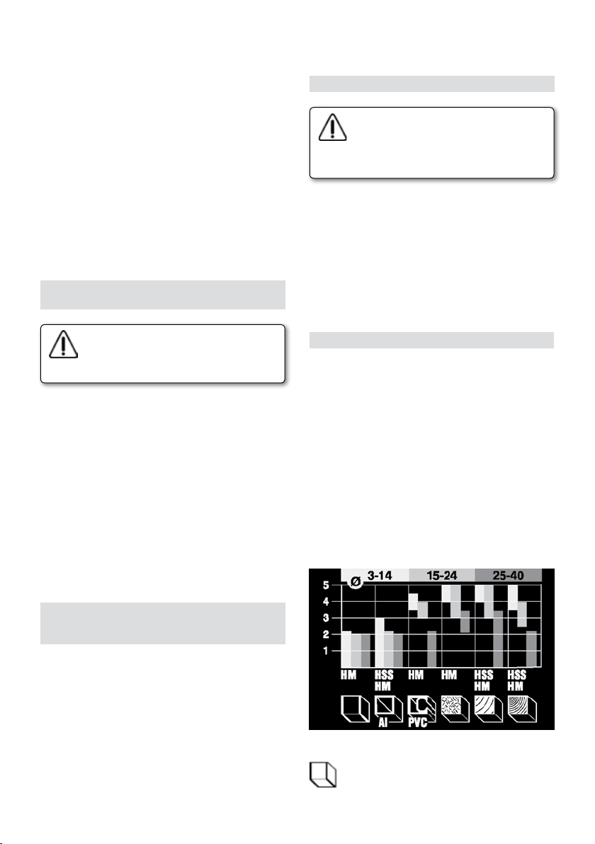
чтобы позволить перемещение регулировочного
штифта 10.
Нажимайте сверху вниз на регулировочный
штифт 10 (рис. 6) пока он не упрется в головку
винта упора-револьвера.
Отрегулируйте рейку глубины 28 (рис. 6) на 0.
Нажмите на регулировочный штифт 10 (рис. 6)
по направлению вверх. Когда будет достигнута
требуемая глубина на шкале 7 (рис. 6),
зафиксируйте круглую ручку 11 (рис. 6).
Освоботите рычаг 24 (рис. 5) и переместите
штифт до нового заданного положения таким
образом, чтобы регулировочный штифт
опирался на винт, после чего зафиксируйте
снова рычаг 24 (рис. 5).
Необходимо проверить грубую регулировку
соответствующим практическим испытанием и, в
случае надобности, исправить ее.
15. ТОЧНАЯ РЕГУЛИРОВКА ГЛУБИНЫ
ФРЕЗЕРОВАНИЯ
Перед началом любой настройки
или замене аксессуаров
отключайте фрезер от сети,
вынимая штекер из розетки.
В случае надобности проведите точную
калибровку. После осуществления грубой
калибровки Вы можете калибровать глубину
фрезерования с точностью до 0,1 мм, вращая
кнопку регулировочного штифта (1 деление = 0,1
мм). Первым делом освободите рычаг 24 (рис.
5). В то время как Вы нажимайте сверху вниз
на фрезу, нажмите на кнопку регулировочного
штифта по направлению стрелки G (рис. 6)
таким образом, чтобы штифт уперся в головку
винта упора-револьвера 16 (рис. 6). Подгоните
нижнюю кнопку к верхней после чего вращайте
верхнюю кнопку по направлению стрелок
Н пока не достигните требуемой величины.
Зафиксируйте снова рычаг 24 (рис. 5).
испытанием и, в случае надобности, исправьте
ее.
17. РАБОТА НА ФРЕЗЕРЕ
Прежде, чам включить фрезер
удостоверьтесь, что напряжение
сети совпадает с указанным
в документации техническиx
характеристик станка.
Включение и выключение соответствует
положениям on/o выключателя.
Включение: нажмите на кнопку деблокировки
8 (рис. 8) после чего нажмите на рукоятку
выключателя 9 (рис. 8).
Непрерывный процесс: Для того, чтобы
заблокировать выключатель в положении on,
нажмите на кнопку 8 и рычаг 9 до конца.
Выключение: нажав снова на рукоятку 9 Вы
выключите фрезер.
18. ПЕРЕМЕННАЯ СКОРОСТЬ (МОДЕЛЬ FR278R)
Вращая кнопку 5 (рис. 1) можно регулировать
скорость от 6.000 до 27.000 оборотов в минуту.
• Позволяет обрабатывать дерево, прокатку,
пластик и алюминий.
• Позволяет поддерживать постоянную скорость
даже при большой нагрузке.
• Позволяет выбирать оптимальную рабочую
скорость.
• Увеличивает срок службы фрезера.
• Обеспечивает плавный пуск фрезера и
предохраняет его от перегрузки.
• Позволяет совершать соответствующую
регулировку и обеспечивает большую надежность
при работе с фрезами большого диаметра.
Таблица для выбора скорости в зависимости от
обрабатываемого материала и диаметра фрезы.
16. ТОЧНАЯ РЕГУЛИРОВКА ГЛУБИНЫ
ФРЕЗЕРОВАНИЯ ПРИ
РАЗМЕЩЕНИИ ФРЕЗЕРА ПОД СТОЛОМ
Держите штифт 10 (рис. 6) над винтом и
пружиной упора-револьвера.
Подгоните винт с отверстием 14 (рис. 6)
к регулировочному штифту 10. Будьте
внимательны, вставляя отвертку в прорезь
винта с отверстием 14. Оказывая давление
на кожух фрезера Вы можете зафиксировать
приблизительную глубину резки и
отрегулировать винт 11 (рис. 6). Осуществите
точную калибровку, вращая верхнюю кнопку по
направлению стрелки Н (рис. 6).
Проверьте точность калибровки практическим
Условное обозначение материалов
Гипсовые панели, легкий футеровочный
материал
35
Page 36

Алюминий
Пластик
Древесно-стружечные плиты
Мягкая древесина
Древесина твердолиственных пород
Найдите подходящую скорость для
обрабатываемого Вами материала путем
практического испытания.
19. ИСПОЛЬЗОВАНИЕ ПАРАЛЛЕЛЬНОЙ
НАПРАВЛЯЮЩЕЙ
Установите боковую направляющую 20 (рис. 7),
вставив оси в отверстия основания 3 (рис. 7) и
отрегулировав их на требуемом расстоянии при
помощи кнопок 2 (рис. 7).
Пользуйтесь кнопкой 18 для более точной
регулировки, затянув оба винта 17 и ослабив
винты 19. Вращая кнопку 18 (рис. 7), Вы сможете
перемещать направляющие. Один оборот гайки
соответствует 1,25 мм. После регулировки
затяните винты 19 (рис. 7).
20. ИСПОЛЬЗОВАНИЕ ШАБЛОННЫХ
НАПРАВЛЯЮЩИХ
Шаблонные направляющие используются для
фрезерования большого количества разных
форм. Выбранная шаблонная направляющая
26 (рис. 1) прикрепляется к основанию двумя
поставляемыми винтами М5. Во время
копирования появляется разница в размере
между шаблоном и обрабатываемой деталью.
При изготовлении шаблона необходимо
учитывать разницу между радиусом шаблонной
направляющей и радиусом инструмента.
21. ФРЕЗЕРОВАНИЕ КРИВОЛИНЕЙНЫХ
ПОВЕРХНОСТЕЙ (рис. 9)
Установите циркуль 22 на одной из
направляющих тяг 27, закрепив его крыльчатой
гайкой. Вставьте направляющую тягу в одно
из отверстий основания станка. Установите
требуемое расстояние между фрезером и точкой
поворота и зафиксируйте кнопкой 2 (рис. 9).
22. КАК ДЕРЖАТЬ И НАПРАВЛЯТЬ ФРЕЗЕР
Держите всегда фрезер обеими руками.
Включайте фрезер исключительно когда он не
36
касается поверхности обрабатываемой детали.
До того как фрезер коснется обрабатываемой
детали он должен быть включен.
Во время работы не нажимайте на фрезер.
Пусть он делает за Вас работу.
Не наклоняйте фрезер во избежание неровного
фрезерования.
Держите в чистоте и в незакрытом виде
вентиляционные решетки электродвигателя.
При работе на фрезере придерживайтесь
следующего порядка:
1. Выберите фрезу и зафиксируйте ее на цанге.
2. Установите требуемую скорость.
3. Включите фрезер.
4. Нажмите сверху на двигатель и закрепите
рычаг блокировки.
5. Проводите фрезерование.
6. Освободите блокировку.
7. Выключите фрезер.
Направление перемещения фрезера (рис. 12)
Во время фрезерования необходимо обращать
внимание на правильное перемещение фрезера
по отношению обрабатываемой детали.
Перемещайте фрезер в обратном направлении
вращению фрезы.
Использование упора-револьвера
При очень глубоком фрезеровании рекомендуется
совершать работу в несколько приемов.
Пользуясь упором-револьвером, Вы сможете
совершить фрезерование в 2 или 3 приема.
Установите глубину фрезерования на
максимальную требуемую глубину 16 (рис.
1). После этого совершайте промежуточные
фрезерования, пользуясь проходами на
меньшей глубине.
23. ЩЕТКИ И КОЛЛЕКТОР
Очень важно производить замену щеток, когда
их минимальная длина равна 5 мм.
Замена щеток
1. Отсоедините фрезер от сети.
2. Открутите винты крышки.
3. Осторожно удалите электронную схему
(только для модели FR278R)
4. Вытащите щеткодержатель и щетки.
5. Замените старые щетки новыми, установите
щеткодержатель на место, проследя за тем,
чтобы он слегка надавливал на коллектор.
6. Установите заново крышку.
Мы рекомендуем включить фрезер на 15 минут
после смены щеток.
Если Вы заметили какие-либо повреждения
или выступы на коллекторе, обратитесь в
технический центр VIRUTEX для ремонта.
Никогда не прибегайте к наждачной бумаге для
устранения этих повреждений.
24. ДОПОЛНИТЕЛЬНЫЕ АКСЕССУАРЫ
Могут быть заказаны следующие
Page 37
факультативные аксессуары
7722116 Переходник диаметра с 8 на 6 мм.
7722115 Переходник диаметра с 8 на 6,35 мм
(1/4”).
6446073 Стандартный шланг всасывания 2,25 м.
7722123 Кольцо копировальное для PLII, шаг 26 мм.
7722161 Кольцо копировальное для PLII, шаг 16 мм.
7722162 Кольцо копировальное для PLII, шаг 34 мм.
7722160 Направляющая для шаблона AGB для
навесных петель.
7722342 Направляющая для шаблона AGB 11-12
7740117 Фреза для шаблона AGB.
25. УРОВЕНЬ ШУМА И ВИБРАЦИИ
Уровень шума и вибрации этого устройства
были измерены в соответствии с европейским
стандартом EN 60745-2-17 и EN 60745-1 и
служат основанием для сравнения с другими
машинами с подобными характеристиками.
Обозначенный уровень вибрации был определен
для основных операций и может использоваться
как начальное значение для того, чтобы
оценить риски, возникающие вследствие
вибрации. Однако, колебания могут достигнуть
уровней, которые отличаются от объявленного
значения при других условиях эксплуатации, с
другими инструментами или с недостаточным
техническим обслуживанием устройства или
его приспособлений, достигая намного более
высокой величины в результате цикла работы
или способа, которым используется устройство.
Необходимо принять меры по обеспечению
безопасности пользователя от повышенной
вибрации, например, поддержание устройства
в чистоте и своевременное техническое
обслуживание устройства, приспособлений
и инструмента, а также организация
продолжительности циклов работы (например,
операционное время под нагрузкой и время
простоя, т.к. сокращение последнего может
существенно влиять на уровень вибрации).
26. ГАРАНТИЯ
Для всех переносных электрических
инструментов фирмы VIRUTEX дается гарантия
сроком на 12 месяцев, начиная от даты
поставки.
Гарантия не распространяется на случаи, когда
ущерб или повреждения были нанесены в
результате неправильного использования или
естественного износа изделия.
Для проведения ремонта изделия обращайтесь
в сервисные центры фирмы VIRUTEX.
27. УТИЛИЗАЦИЯ ЭЛЕКТРИЧЕСКОГО
ИНСТРУМЕНТА
Никогда не выбрасывайте электрический
инструмент вместе с бытовыми отходами.
Переработка оборудования, оснастки и
тары должна осуществляться методами,
минимизирующими отрицательное воздействие
на окружающую среду. Свяжитесь с
соответствующими органами, регулирующими
эти вопросы в вашей стране
Применяется для стран Евросоюза и
Европейских стран с селективной системой
сбора отходов:
В случае если указанный символ присутствует
на оборудовании или в сопроводительной
документации, в конце жизненного цикла
инструмента он не может быть утилизирован с
бытовыми отходами.
В соответствии с требованиями Европейской
Директивы 2002/96/EC, пользователь может
обратиться к властям для поиска, где и как
он может сдать продукт на переработку
максимально дружественным для окружающей
среды и безопасным способом.
Фирма VIRUTEX сохраняет за собой право
на внесения технических изменений без
предварительного объявления об этом.
РOLSKI
FREZARKA GÓRNOWRZECIONOWA FR277R
ELEKTRONICZNA FREZARKA GÓRNOWRZECIONOWA FR278R
(Rysunki na stronie 43)
WAŻNE
Przed przystąpieniem do pracy
z urządzeniem należy dokładnie
przeczytać niniejszą INSTRUKCJĘ
OBSŁUGI oraz załączoną
INSTRUKCJĘ BEZPIECZEŃSTWA.
Należy się upewnić, że wszystkie
informacje zostały zrozumiane przed
użyciem urządzenia po raz pierwszy.
1. DANE TECHNICZNE
Typ.............................................FR277R
Uniwersalny silnik…………..…......………...50/60 Hz
Moc...............................................................1010 W
Prędkość bez obciążenia..........................24000/min
Tulejka.....................................................8 mm
37
Page 38

Głębokość frezowania...............................0-50 mm
Maksymalna średnica frezu.............................40 mm
Obrotowa blokada
głębokości……...ustawianie 3 pozycji głębokości
Waga........................................................2,9 kg
Poziom pomiaru ciśnienia akustycznego....91 dB(A)
Poziom napięcia akustycznego.................102 dB(A)
Margines błędu..........................................K = 3 dbA
Stosować środki ochrony słuchu!
Poziom wibracji (ramie-ręka).................ah: <4.4 m/s
Margines błędu........................................K: 1.5 m/s
Typ............................................................FR278R
Uniwersalny silnik.....................................50/60 Hz
Moc..................................................1300 W
Prędkość bez obciążenia................6000-27000/min
Tulejka................................................8 mm
Głębokość frezowania...............................0-50 mm
Maksymalna średnica frezu...........................40 mm
Obrotowa blokada
głębokości..................ustawianie 3 pozycji głębokości
Waga..................................................3kg
Poziom pomiaru ciśnienia akustycznego...91 dB(A)
Poziom napięcia akustycznego...............102 dB(A)
Margines błędu.......................................K = 3 dbA
Stosować środki ochrony słuchu!
Poziom wibracji (ramie-ręka)...........ah: <4.4 m/s
Margines błędu....................................K: 1.5 m/s
2. PRZEZNACZENIE URZĄDZENIA
Frezarka górnowrzecionowa jest profesjonalnym
urządzeniem używanym do obróbki drewna, plastiku i aluminium. Jest również doskonała do pracy z
szablonami, przycinania brzegów, konturów, wycinania kopii, okręgów, elips, pomniejszania, robienia
ram lub wykonywania inskrypcji.
3. WSKAZÓWKI BEZPIECZEŃSTWA PRZY
OBSŁUDZE URZĄDZENIA
Przed użyciem urządzenia należy uważnie
przeczytać instrukcję obsługi oraz instrukcję
bezpieczeństwa.
• Przed przystąpieniem do jakichkolwiek prac
naprawczych, konserwacyjnych lub dostosowawczych, odłącz urządzenie od źródła zasilania.
• Nie używać urządzenia jeśli kabel jest uszkodzony. W takim przypadku należy bezzwłocznie
odłączyć urządzenie od źródła zasilania, lecz
unikać przy tym kontaktu z uszkodzonym kablem.
• Zawsze utrzymuj kabel z dala od ruchomych
elementów urządzenia.
• Korzystaj jedynie z przedłużaczy, które
można używać także na zewnątrz warsztatów,
posiadających wtyczkę z osłoną.
38
• Kable przedłużacza muszą mieć minimalny
przekrój 1,5mm2, kable muszą być całkowicie
rozwinięte.
• Podłączaj urządzenie do źródła zasilania tylko jeśli
włącznik jest ustawiony w pozycji OFF.
• Zawsze noś odzież ochroną, okulary ochronne i
odpowiednie obuwie.
• Zawsze trzymaj frezarkę w dwóch rękach.
• Wyłączaj urządzenie po zakończeniu frezowania.
• Zanim odstawisz frezarkę, poluzuj jej stolik roboczy.
• Zawsze odstawiaj narzędzie na płaskiej, czystej
powierzchni.
2
• Nie kładź żadnych innych narzędzi na elemencie,
2
który poddajesz obróbce.
• Element poddawany obróbce musi być czysty,
wolny od resztek materiałów, odpadków po innej
obróbce, etc.
• Miejsce pracy zawsze powinno być oświetlone
w odpowiedni sposób. Zabronione jest używanie
frezarki w pomieszczeniach z łatwopalnymi substancjami i gazami. Włączaj/wyłączaj urządzenie
jedynie za pomocą wyłącznika, a nie za pomocą
samej wtyczki.
• W czasie pracy uważaj na śruby, gwoździe i
inne obiekty mogące się znajdować w elemencie
poddawanym obróbce.
• Rozpoczynaj frezowanie dopiero wtedy, gdy
urządzenie osiągnie pełną prędkość roboczą.
• Uważaj na możliwość nagłego wstrząsu przy
uruchamianiu FR277R i FR278R.
• Unikaj niepożądanego uruchamiania urządzenia.
2
• Zawsze używaj nieuszkodzonych i naostrzonych
2
frezów.
• Gdy nie używasz urządzenia, przechowuj je w
suchym miejscu, zabezpieczone przed wilgocią.
• Nie zakładaj do pracy luźnej odzieży ani biżuterii,
jako że urządzenie może chwycić i wciągnąć te
elementy. Jeśli masz długie włosy, zawsze zakładaj
ochronne przykrycie głowy. Przy pracy na zewnątrz,
ubieraj obuwie antypoślizgowe.
• Na wypadek zablokowania się urządzenia,
bezzwłocznie wyłącz je i odłącz od źródła zasilania.
• Element poddawany obróbce musi być unieruchomiony.
• Prowadź urządzenie po elemencie do obróbki tylko, gdy jest ono włączone (w pozycji ON).
Wyłącz urządzenie (przełącz na pozycję OFF) po
podniesieniu urządzenia nad element poddawany
obróbce.
• Używaj jedynie oryginalnych części zamiennych i
akcesoriów.
4. STANDARDOWE WYPOSAŻENIE
Frezarkę
Prowadnicę na ramionach
Specjalną prowadnicę (cyrkiel)
Adapter do rury do urządzenia odpylającego
Instrukcje obsługi, karty gwarancyjne
Page 39

5. PRZYGOTOWANIE URZĄDZENIA DO FREZOWANIA
10. WYBÓR FREZU
Zawsze odłączaj urządzenie od
źródła zasilania przed przystąpieniem
do jakichkolwiek dostosowań lub
wymiany akcesoriów.
6. ODCIĄG
Procesy frezowania i żłobienia powodują powstawanie pyłów, które mogą zagrażać zdrowiu i
bezpieczeństwu pracy. Korzystanie z urządzenia
odpylającego zapobiega kumulowaniu się tych
pyłów w otoczeniu, a co za tym idzie, ich wdychaniu
oraz ułatwia usuwanie odpadków.
7. ZAKŁADANIE ADAPTERA DO URZĄDZENIA
ODPYLAJĄCEGO
Załóż adapter do urządzenia odpylającego 15 (Rys.
2) na płycie podstawy 3 (Rys. 2) w taki sposób, że
zaczepy A (Rys. 2) znajdą się wewnątrz otworu
adaptera.
Dosuń otwór adaptera w kierunku A (Rys. 2) do
krawędzi blokującej C tak, aby boczna blokada D
"wskoczyła” samoczynnie w krawędź B (Rys. 2).
Podłącz wąż urządzenia odpylającego
bezpośrednio do adaptera 15 (Rys. 3), lub podłącz
go do węża odciągu z nagwintowaną końcówką do
ekstrakcji odpadków 4 (Rys. 3).
Zamontuj wąż w jego miejscu poniżej osłony silnika.
Zamontuj górny adapter urządzenia odpylającego
dociskając go w kierunku C (Rys. 3), dopóki nie
"wskoczy" pomiędzy osłonę silnika a obudowę.
Następnie połącz dolną część węża z adapterem
15 wsuwając go w kierunku D (Rys. 3).
Wkręcane połączenie umożliwia lepsze pole
widzenia oraz ułożenie węża odciągu w dogodnej
pozycji. Średnica adaptera wynosi 35 mm, co
odpowiada średnicy standardowych węży urządzeń
odpylających.
Używając opcjonalnego Węża systemu odpylania
Nr kat. 6446073, frezarka może być podłączona
do naszego urządzenia odpylającego AS182K,
AS282K lub AS382L, lub do jakichkolwiek innych
urządzeń odpylających za pośrednictwem złączki.
Zawsze używaj frezów o wymiarach
odpowiadających tulejce frezarki.
Liczba obrotów nie może być wyższa
niż dozwolona prędkość pracy frezarki. Zabronione jest używanie frezów o
średnicy większej niż 40 mm.
Frezy HM są adekwatne do pracy na twardszych
materiałach i umożliwiają pracę na wysokich
obrotach.
11. ZAKŁADANIE FREZÓW
Zawsze odłączaj urządzenie od źródła
zasilania przed przystąpieniem do jakichkolwiek dostosowań lub wymiany
akcesoriów.
Zamontuj frez w tulejce 25 (Rys. 1) za pomocą gałki
13 (Rys. 1). Działaj według następującej kolejności:
• Odkręć 1-2 ruchami gałkę z włożoną w środku
tulejką.
• Włóż frez. Frez musi być włożony co najmniej na
głębokość 20mm. Wciskając przycisk blokujący 12
(Rys. 1, 4) zablokuj trzpień, po czym zaciśnij gałkę
13 (Rys. 1) za pomocą klucza 23 (Rys. 1). Zbyt
mocne zaciskanie może doprowadzić do zniszczenia trzpienia.
• Nigdy nie zakręcaj do końca gałki 13 jeśli nie ma
w niej włożonego frezu. Grozi to uszkodzeniem
tulejki!
Przy usuwaniu frezu, najpierw poluzuj gałkę 13
(Rys. 1), a następnie kontynuuj odkręcanie, dopóki
frez będzie całkiem luźno.
12. WYMIANA TULEJKI
Tulejka musi być zamocowana w gałce 13 (Rys.
10). Jeśli chcesz ją wymienić, wyciągnij ją z gałki za
pomocą małego śrubokręta, wkładając go pomiędzy
gałkę a tulejkę. Włóż nową tulejkę, mocno
wciskając ją w gałkę (do usłyszenia "kliknięcia").
8. ZDEJMOWANIE GÓRNEGO ADAPTERA DO
URZĄDZENIA ODPYLAJĄCEGO (Rys. 3)
Należy w pierwszej kolejności zdjąć wąż z adaptera
15 w kierunku E, a następnie wypchnąć jego górną
część w kierunku F (Rys. 3).
9. ZDEJMOWANIE DOLNEGO ADAPTERA DO
URZĄDZENIA ODPYLAJĄCEGO (Rys. 2)
Zdejmij wąż z adaptera. Naciśnij boczną blokadę D
adaptera 15 tak, aby go zwolnić, po czym wypchnij
go w kierunku B (Rys. 2).
Tulejka musi być włożona w gałkę
w taki sposób, że gałka oraz tulejka
będą na równym poziomie.
13. DOPASOWANIE STOLIKA FREZARKI
Dopasuj stolik frezarki do wymaganej wysokości za
pomocą dźwigni 24 (Rys. 5). Wbudowana sprężyna
teleskopowa powoduje powrót stolika do pozycji
pierwotnej po zwolnieniu dźwigni.
14. DOSTOSOWANIE GŁĘBOKOŚCI FREZOWANIA
39
Page 40
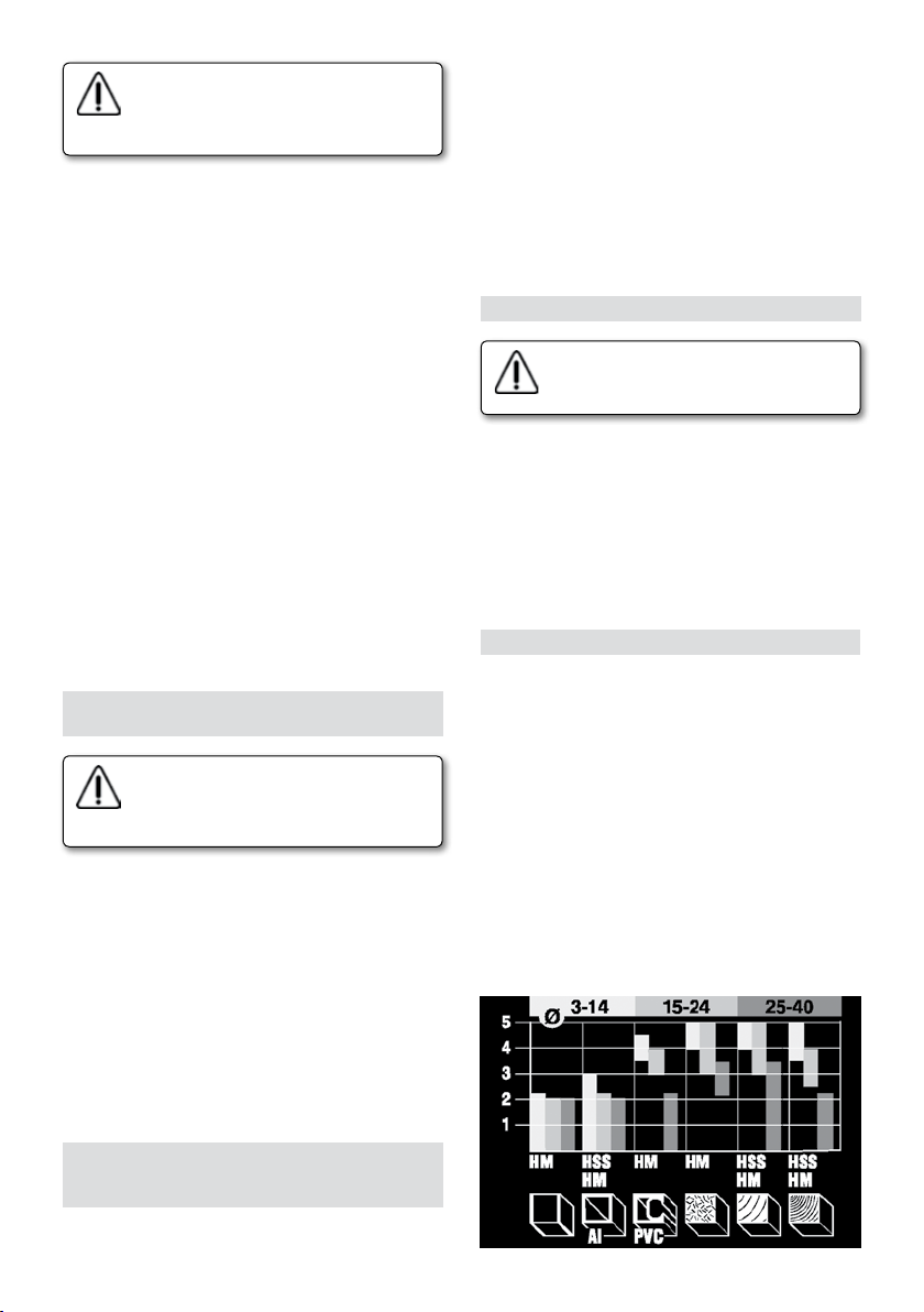
Zawsze odłączaj urządzenie od źródła
zasilania przed przystąpieniem do jakichkolwiek dostosowań lub wymiany
akcesoriów.
Ustaw głębokość frezowania za pomocą śrub na
deektorze 16 (Rys. 6), dostosowując jednocześnie
trzpień 10 (Rys. 6) za pomocą wskaźnika 28
(Rys.6). Trzy śruby na deektorze umożliwiają
ustawienie trzech głębokości frezowania. Zakres
ustawienia wynosi 50 mm.
Ustaw urządzenie na elemencie do obróbki. Zwolnij
dźwignię 24 (Rys. 5) i powoli opuść urządzenie
w dół. Gdy frezarka dotknie elementu, zablokuj
dźwignię 24 (Rys 5).
Ustaw (obracając) deektor 16 (Rys. 6) na pozycji
pożądanej głębokości frezowania. Odkręć śrubę
motylkową 11 (Rys. 6), zwalniając w ten sposób
trzpień 10. Pchnij w dół trzpień 10 (Rys. 6) tak, aby
ustawić go na śrubie deektora. Ustaw wskaźnik
głębokości 28 (Rys. 6) na 0. Pchnij trzpień 10 (Rys.
6) w górę. Gdy osiągniesz wymaganą głębokość na
skali 7 (Rys. 6), zaciśnij śrubę motylkową 11 (Rys. 6).
Zwolnij dźwignię 24 (Rys. 5) i ustaw trzpień w
nowej, dostosowanej pozycji, w taki sposób, że
trzpień 10 (Rys. 6) opierać się będzie na śrubie, po
czym zaciśnij ponownie dźwignię 24 (Rys 5).
Należy sprawdzić ustawioną w ten sposób
głębokość, wykonując test praktyczny i w razie
potrzeby dokonać poprawek.
15. PRECYZYJNE DOSTOSOWANIE GŁĘBOKOŚCI
FREZOWANIA
Zawsze odłączaj urządzenie od źródła
zasilania przed przystąpieniem do jakichkolwiek dostosowań lub wymiany
akcesoriów.
W razie konieczności możesz wykonać precyzyjne ustawienie głębokości frezowania. Po
dokonaniu ustawienia opisanego w poprzednim
rozdziale, możesz ustawić wymaganą głębokość z
dokładnością do 0,1mm, obracając pokrętło trzpienia (1 linijka=0.1mm).
Na początku zwolnij dźwignię 24 (Rys. 5). W
trakcie opuszczania urządzenia w dół, wciśnij górny
przycisk pokrętła trzpienia w kierunku G (Rys. 6),
tak aby oparł się na śrubie (trał w rowek śruby)
deektora 16 (Rys. 6). Przekręcaj górne pokrętło
trzpienia w kierunku H, do uzyskania pożądanej
głębokości. Zaciśnij ponownie dźwignię 24 (Rys 5).
6) deektora do trzpienia 10. Zwróć szczególną
uwagę aby trać końcem trzpienia w rowek śruby
będącej poniżej gałki 14. naciskając na obudowę
urządzenia, uzyskasz odpowiednią głębokość
frezowania, po czym zaciśnij śrubę motylkową 11
(Rys. 6). Precyzyjne ustawienie głębokości dokonuje się poprzez obracanie górnego pokrętła trzpienia
w kierunku H (Rys. 6).
Należy sprawdzić ustawioną w ten sposób
głębokość, wykonując test praktyczny i w razie
potrzeby dokonać poprawek.
17. PRACA Z FREZARKĄ
Zawsze się upewnij czy zasilanie w
sieci odpowiada zasilaniu podanemu
na tablicy znamionowej urządzenia.
Włączanie/wyłączanie
Włączanie: Wciśnij przycisk 8 (Rys. 8), a następnie
wciśnij dźwignię włącznika 9 (Rys. 8).
Praca ciągła: Gdy urządzenie jest włączone, wciśnij
głębiej przycisk 8 odblokowując go. Wciśnij przycisk
8 i dźwignię 9 do końca, po czym po kolei zwolnij
najpierw dźwignię 9 a potem przycisk 8.
Wyłączanie: Wyłączysz urządzenie wciskając
ponownie dźwignię 9.
18. REGULACJA PRĘDKOŚCI (MODEL FR278R)
Przycisk dostosowawczy 5 (Rys.1) umożliwia
regulację prędkości od 6000 do 27000 r.p.m.
Stała kontrola elektroniczna.
• Umożliwia frezowanie w każdego rodzaju drewnie,
laminatach, materiałach plastikowych i aluminiowych.
• Umożliwia ustawienie stałej ilości obrotów
niezależnie od rodzaju obciążenia.
• Umożliwia ustawienie optymalnej ilości obrotów.
• Przyczynia się do przedłużenia żywotności urządzenia.
• Funkcja "soft start” i ochrona przed przeładowaniem.
• Umożliwia wykonywanie niezbędnych dostosowań
i zapewnia większe bezpieczeństwo podczas pracy
z frezami o większych średnicach.
Tabela odniesienia pomocna przy wyborze ilości
obrotów adekwatnie do obrabianego materiału i
średnicy frezu.
16. PRECYZYJNE DOSTOSOWANIE GŁĘBOKOŚCI
FREZOWANIA, GDY FREZARKA JEST ZAMOCOWANA DO STOLIKA
Oprzyj trzpień 10 (Rys. 6) na wyżłobionej śrubie
deektora. Przymocuj wyżłobioną śrubę 14 (Rys.
40
Page 41

Symbole materiałów
Płyty gipsowe
Aluminium
Plastiki
Panele
Drewno miękkie
Drewno twarde
Sprawdź optymalne ilości obrotów za pomocą
testów praktycznych.
19. UŻYCIE PROWADNICY RÓWNOLEGŁEJ
Zamontuj prowadnicę równoległą 20 (Rys.
7) wkładając jej pręty w otwory w podstawie
urządzenia 3 (Rys. 7), po czym dostosuj je do
wymaganej głębokości za pomocą dwóch śrub
motylkowych 2 (Rys. 7).
Użyj pokrętła 18 (Rys. 7) do bardziej precyzyjnego dostosowania głębokości zaciskając śruby
motylkowe 17 (Rys. 1) oraz poluzowując śruby
motylkowe 19. przekręcając pokrętło 18, ustawiasz
frez bliżej lub dalej względem prowadnicy. Poprzez
pełny obrót pokrętła, zmieniasz dystans o 1,25 mm.
Po dokonaniu dostosowań, zaciśnij obie śruby 19
(Rys. 7).
20. PIERŚCIENIE PROWADZĄCE
Pierścienie prowadzące służą do odwzorowywania rozmaitych kształtów szablonów. Adekwatny
pierścień prowadzący 26 (Rys. 1) jest mocowany
do podstawy 3 (Rys. 1) za pomocą dwóch śrub.
W trakcie kopiowania, widoczna staje się różnica
w rozmiarach między szablonem a elementem
poddawanym frezowaniu. Przy przygotowywaniu szablonu należy zawsze uwzględnić różnicę
pomiędzy promieniem pierścienia 13 (Rys. 11) a
promieniem frezu.
21. FREZOWANIE PO OKRĘGU ZA POMOCĄ
CYRKLA (Rys. 9)
Zamocuj końcówkę cyrkla 22 na jednym z ramion
27, zaciśnij za pomocą śruby motylkowej. Włóż tak
skomponowany cyrkiel w jeden z otworów w podstawie frezarki. Ustaw wymagany dystans pomiędzy
frezarką a punktem przyłożenia cyrkla i zaciśnij za
pomocą śruby motylkowej.
22. TRZYMANIE I PROWADZENIE URZĄDZENIA
W trakcie pracy trzymaj urządzenie dwoma rękoma.
Wolno uruchamiać urządzenie tylko gdy nie dotyka
ono powierzchni obrabianego elementu.
Zanim frezarka dosięgnie obrabianego elementu,
urządzenie należy włączyć.
Nie naciskaj na urządzenie w czasie pracy, niech
frezarka wykonuje pracę za Ciebie.
Nie przechylaj urządzenia aby uniknąć nierównego
frezowania.
Upewnij się, że otwory wentylacyjne nie są zasłonięte.
Podczas pracy z frezarką postępuj według
kolejności:
1. Wybierz frez i umieść go w tulejce.
2. Ustaw wymaganą głębokość frezowania.
3. Włącz urządzenie (on).
4. Opuść silnik w dół, zablokuj dźwignię.
5. Rozpocznij frezowanie.
6. Zwolnij blokadę.
7. Wyłącz urządzenie (o).
Kierunek ruchu urządzenia (Rys. 12)
Musisz zwracać uwagę aby w trakcie pracy
przesuwać urządzenie w odpowiednim kierunku po
obrabianym elemencie.
Przesuwaj frezarkę w kierunku przeciwnym do
kierunku obrotów frezu.
Deektor
Przy frezowaniu na większe głębokości, zalecamy
stopniowe frezowanie na coraz większą głębokość.
Korzystając z deektora, można frezować w dwóch
lub trzech etapach (stopniach).
Sprawdź czy wymagana maksymalna głębokość
odpowiadałaby maksymalnej głębokości deektora
16 (Rys. 1). Pierwsze dwa frezowania wykonaj na
najniższej i na średniej głębokości deektora.
23. SZCZOTKI I KOLEKTOR
Ważne jest aby wymieniać szczotki kiedy osiągną
długość 5 mm.
Wymiana szczotek.
1.Odłączyć maszynę od prądu.
2.Usunąć śruby z pokrywy.
3.Ostrożnie usunąć obwód elektroniczny (dotyczy
tylko modelu FR278R).
4.Wyciągnąć trzymadełko szczotek i szczotki z
urządzenia.
5.Wymienić szczotki i trzymadełko szczotek, upewniając
się, że wywierają nieznaczny nacisk na kolektor.
6. Zainstalować ponownie jak powyżej. Zaleca się
włączenie maszyny na ok. 15 minut po wymianie
szczotek.
Jeśli na kolektorze widoczne są oznaki zużycia lub
otarcia, należy oddać urządzenie do naprawy w
serwisie technicznym VIRUTEX.
Nigdy nie używaj do tej operacji papieru ściernego.
24. AKCESORIA DODATKOWE
Podane akcesoria mogą być dołączone opcjonalnie:
41
Page 42

7722116 redukcja z 8 do 6 mm
7722115 redukcja z 8 do 6,35 mm (1/4’’)
6446073 standardowy zestaw do urządzenia
odpylającego o długości 2,25 m
7722123 pierścień prowadzący do wycinania
połączeń "na pióro" na szerokość 26 mm.
7722161 pierścień prowadzący do wycinania
połączeń "na pióro" na szerokość 16 mm.
7722162 pierścień prowadzący do wycinania
połączeń "na pióro” na szerokość 34 mm.
7722160 pierścień prowadzący do szablonu AGB
do zawiasów
7722342 pierścień prowadzący do szablonu AGB
7740117 frez do szablonu AGB
25. HAŁAS I POZIOM WIBRACJI
Hałas i poziom wibracji urządzenia zostały zmierzone według europejskich standardów EN50144.
Zaleca się, aby używać dodatkowych środków
ochronnych uszu.
26. GWARANCJA
Wszystkie narzędzia rmy VIRUTEX są objęte
12-miesięczną gwarancją od daty zakupu. Gwarancja nie obejmuje naprawy usterek powstałych w wyniku nieprawidłowego użytkowania urządzenia lub
naturalnego wyeksploatowania i zużycia urządzenia.
Wszystkie naprawy powinny być wykonane w ocjalnym punkcie serwisowym rmy VIRUTEX.
27. UTYLIZACJA SPRZĘTU ELEKTRYCZNEGO
Nigdy nie wyrzucaj sprzętu elektrycznego razem z
odpadkami domowymi. Utylizuj sprzęt, akcesoria i
opakowania w sposób, który zminimalizuje jakikolwiek niekorzystny wpływ na środowisko. Postępuj
zgodnie z przepisami aktualnymi w Twoim kraju.
Wytyczne zgodne z Unią Europejską i krajami
europejskimi stosującymi się do zaleceń zasad
selekcji odpadów:
Jeśli na produkcie, lub w dołączonej do niego
dokumentacji pojawia się ten symbol, produkt taki
nie może być po zakończeniu swojej żywotności
zutylizowany wraz z odpadkami domowymi.
Zgodnie z Dyrektywą Europejską 2002/96/
EC, użytkownik może skontaktować się z
przedsiębiorstwem, w którym zakupił produkt, lub z
odpowiednimi władzami lokalnymi, aby dowiedzieć
się gdzie i jak może zutylizować produkt w sposób
bezpieczny i przyjazny środowisku.
VIRUTEX zastrzega sobie prawo do dokonywania
zmian technicznych w urządzeniach bez uprzedzenia
42
Page 43

Fig. 1
43
Page 44

Fig. 2
Fig. 4
44
Fig. 3
Fig. 5
Page 45

Fig. 6
Fig. 7
Fig. 8
45
Page 46

Fig. 9
Fig. 10 Fig. 11
Fig. 12
Page 47

Page 48
http://www.virutex.es/registre
Acceda a toda la información técnica.
Access to all technical information.
Accès à toute l’information technique.
Zugang zu allen technischen Daten.
Accedere a tutte le informazioni tecniche.
Aceso a todas as informações técnicas.
Dostęp do wszystkich informacji technicznych.
Доступ ко всей технической информации.
7796502 092021
08191 Rubí (Barcelona) (Spain)
Virutex, S.A.
Av. de la Llana, 57
www.virutex.com
 Loading...