


Fresadora tupí
Router
Défonceuse
Tischfräsmaschine
Fresatrice toupie
Fresadora tupia
Фрезер
FR277R / FR278R
MANUAL DE INSTRUCCIONES
OPERATING INSTRUCTIONS
MODE D’ EMPLOI
GEBRAUCHSANWEISUNG
MANUALE D’ISTRUZIONI
MANUAL DE INSTRUÇÕES
ИНСТРУКЦИЯ ПО ЭКСПЛУАТАЦИИ
7
ENGLISH
FR277R ROUTER
FR278R ELECTRONIC ROUTER
(ILUSTRATIONS IN PAGE 39)
Important
Read these OPERATING INSTRUCTIONS
and the attached GENERAL SAFETY
INSTRUCTIONS LEAFLET carefully before
using the machine. Make sure you have
understood them before operating the
machine for the first time.
Keep both sets of instructions for any
future queries.
1. TECHNICAL DATA
Type.........................................................FR277R
Universal motor.........................................50/60 Hz
Input power..................................................1010W
No-load speed.......................................24,000/min
Standard chuck diameter.................................8 mm
Routing depth............................................0-50 mm
Maximum bit diameter...................................40 mm
Revolving depth gauge...3-position depth adjustment
Weight..........................................................2.9 Kg
Weighted equivalent continuous
acoustic pressure level A.............................................91 dBA
Acoustic power level A..................................................102 dBA
Uncertainty...................................................................K = 3 dbA
Wear ear protection!
Vibration total values..............................................ah: 4.4 m/s
2
Uncertainty....................................................................K: 1.5 m/s
2
Type........................................................FR278R
Universal motor.........................................50/60 Hz
Input power..................................................1300W
No-load speed.............................6,000-27,000/min
Standard chuck diameter.................................8 mm
Routing depth.............................................0-50 mm
Maximum bit diameter...................................40 mm
Revolving depth gauge..3-position depth adjustment
Weight.............................................................3 Kg
Weighted equivalent continuous
acoustic pressure level A.............................................91 dBA
Acoustic power level A..................................................102 dBA
Uncertainty...................................................................K = 3 dbA
Wear ear protection!
Sin embargo, el nivel de vibraciones puede llegar a ser
muy diferente al valor declarado en otras condiciones
de aplicación, con otros útiles de trabajo o con un
mantenimiento insuficiente de la herramienta eléctrica
y sus útiles, pudiendo llegar a resultar un valor mucho
más elevado debido a su ciclo de trabajo y modo de uso
de la herramienta eléctrica.
Por tanto, es necesario fijar medidas de seguridad de
protección al usuario contra el efecto de las vibraciones,
como pueden ser mantener la herramienta y útiles de
trabajo en perfecto estado y la organización de los
tiempos de los ciclos de trabajo (tales como tiempos
de marcha con la herramienta bajo carga, y tiempos de
marcha de la herramienta en vacío y sin ser utilizada
realmente ya que la reducción de estos últimos puede
disminuir de forma sustancial el valor total de exposición).
26. GARANTÍA
Todas las máquinas electroportátiles VIRUTEX, tienen
una garantía válida de 12 meses a partir del día de su
suministro, quedando excluidas todas las manipulaciones
o daños ocasionados por manejos inadecuados o por
desgaste natural de la máquina. Para cualquier reparación
dirigirse al servicio oficial de asistencia VIRUTEX S.A.
27. RECICLAJE DE LAS
HERRAMIENTAS ELÉCTRICAS
Nunca tire la herramienta eléctrica con el resto de resi-
duos domésticos. Recicle las herramientas, accesorios y
embalajes de forma respetuosa con el medio ambiente.
Respete la normativa vigente de su país.
Aplicable en la Unión Europea y en países europeos
con sistemas de recogida selectiva de residuos:
La presencia de esta marca en el producto o en el
material informativo que lo acompaña, indica que al
finalizar su vida útil no deberá eliminarse junto con
otros residuos domésticos.
Conforme a la Directiva Europea 2002/96/CE los usuarios
pueden contactar con el establecimiento donde adquirie-
ron el producto, o con las autoridades locales pertinentes,
para informarse sobre cómo y dónde pueden llevarlo
para que sea sometido a un reciclaje ecológico y seguro.
VIRUTEX se reserva el derecho de modificar sus productos
sin previo aviso.
8
wear a protective head-covering. When working outside,
wear non-skid footwear.
• In case the tool is blocked, immediately switch off the
tool and disconnect the plug.
• Clamp the workpiece.
• Guide only switched on tool towards the workpice.
Switch off the tool when you when you have lifted the
tool from the workpiece.
• Use only original parts and accessories.
4. PACKAGE CONTENTS
Router
Parallel guide
Compass
Wrench
Dust extraction adapter
Instructions for use, guarantee card
5. PREPARING THE TOOL FOR MILLING
Always disconnect the plug from power
source before making any adjustments
or changing any accessory.
6. DUST SUCTION
Milling and grinding wood generate sawdust and dust
that endanger safety and health. Using dust suction
prevents air pollution for breathing and makes easier
removal of wastes.
7. MOUNTING DUST EXTRACTION ADAPTER
Put the dust extraction adapter 15 (Fig. 2) baseplate 3
(Fig. 2) so that the twin column guide A (Fig. 2) is inside
the mouth of the dust extraction adapter.
Push the mouth with the right hand thumb in the
direction A (Fig. 2) towards the locking edge C so that
the lock D on the periphery is automatically cought in
the edge B (Fig. 2)
Connect the hose of a vacuum cleaner directly to the
dust extraction adapter 15 (Fig. 3), or connect it with a
suction hose with a turning connection for extracting
dust 4 (Fig. 3).
Fix the latter into the corresponding place below the
motor cover.
Mount the upper dust extraction adapter by pushing
it in the directions C until it snaps between the motor
gerabox and the motor cover. Then attach the lower
part of the hose to the dust extraction adapter 15 in
the direction D (Fig. 3).
Turning connection enables better view of the milling
area and setting the vacuum cleaner hose in the most
favourable position. The diameter of the dust extrac-
Vibration total values..............................................a
h
: 4.4 m/s
2
Uncertainty....................................................................K: 1.5 m/s
2
2. OPERATION RANGE
The router is a professional power tool intended for
surface milling of wood, plastics and aluminium. It is an
excellent tool for milling templates, contours, circles and
grooves, for making finishing laths and picture frames
and for engraving inscriptions.
3. SAFETY INSTRUCTIONS FOR
MACHINE OPERATION
Read the instructions for use and safety instructions
carefully before using the tool.
• Disconnect the plug before you perform any work
on the tool.
• Do not use the tool if the mains lead is damged. If the
mains lead is damaged while working, do not touch it
but immediately disconnect the plug.
• Always keep the mains lead away from moving parts
of the tool.
Direct the mais lead to the rear fo the tool.
• Use only extension cord that is intended for outdoor
use and equipped with a splash-proof coupling-socket.
Connect the tool via a fault current (FI) circuit beaker
with a triggering current of 30 mA maximum.
• Wires of the extension cable must have a minimum
section of 1,5 mm2 and the cable must be fully unwound.
• Plug in the tool only if the switch is turned off.
• Always wear personal protective equipment, glasses
and footwear.
• Always hold the router with both hands.
• Switch off the motor after you have finished milling.
• Before you put down the tool, loosen the router table.
• Always put down the tool on a horizontal and clean
surface.
• Do not put any other tools on the workpiece.
• Workpiece must be clean, without any rests of ma-
terials, sawdust...
• Work place should have adequte lights, it is forbiidden
to use the tool in rooms with inflammable substances
and gases, switch on/off the tool only by the switch and
not by disconnesting the plug.
• Be careful of screws, nails and other objects in the
workpiece while milling.
• Start working only when the tool has reached full speed.
• Be aware of the sudden impact when the FR277R and
FR278R power tool is switched on.
• Prevent unintentional switching on of the tool.
• Always use undamaged and sharp router bits.
• When you do not use the tool, store it in a dry place
protected from dust.
• Do not wear loose clothes of jewelry the tool could
take hold of and pull it towards it. If you have long hair,
9
tion adapter is 35 mm, which corresponds to hoses of
standard vacuum cleaners.
Using STANDARD DUST COLLECTOR ATTACHMENT
Ref.6446073 (optional), the router may be connected
to our AS182K, AS282K, AS382L aspirator or to any
other industrial aspirator via the aspiration connector.
8. REMOVING UPPER DUST
EXTRACTION ADAPTERS (Fig. 3)
With the hose can be removed by first taking off the hose
from the dust extraction adapter 15 in the direction E,
and then push with the left hand thumb the upper part
of the dust extraction adapter in the direction F (Fig. 3).
9. REMOVING LOWER DUST
EXTRACTION ADAPTERS (Fig. 2)
Take off the hose of the dust extraction adapter 4. Press
the lock D on the periphery of the adapter 15 that much
to release it and push in the direction of the arrow B.
Then take off the adapter (Fig. 2)
10. CHOOSING A ROUTER
Always use router bits of such diameters that
correspond the lock collet. The number of re-
volutions must not be higher then the allowed
speed of the router. It is forbidden to use
router bits of diamenters larger than 40 mm.
Carbide tipped bits (HM) are suitable for working hard
materials and enable higher cutting speeds.
11. CLAMPING ROUTER BITS
Always disconnect the plug from power
source before making any adjustments
or changing any accessory.
Clamp the bit with the collet 25 (Fig. 1) and the nut 13
(Fig. 1). The correct order for clamping bits:
• Unscrew the nut with the inserted collet on the spindle
by 1-2 threads.
• Insert a bit. The bit must be inserted at least 20 mm
deep. Pushing the lock-off button 12 (Fig. 1, 4) you block
the spindle, and then fasten the clamp nut 13 (Fig. 1)
with the fork wrench 23 (Fig. 1). Excessive fastening of
the nut can damage the thread on the spindle.
• Never drive in the clamp nut 13 till the end of the
shaft when there is no bit in the collet. Danger of
damaging the collet!
When removing the bit with one turn, first loosen the
clamp nut 13 (Fig. 1), and then continue unscrewing it
till the bit is completely loose.
12. CHANGING CLAMPING COLLET
Collet must be fixed in the clamp nut 13 (Fig. 10). When
you want to change it, pull it from the nut using a small
screwdriver which you insert between the nut and the
collet. Insert a new collet with a strong push into the
clamp nut (click).
Collet must be inserted in the nut in such
manner that the nut and the collet are
even at the front side.
13. FIXING ROUTER TABLE
Fix the router table to the desired height by the lever
24 (Fig. 5). Built-in telescopic spring returns the router
table in the original position after releasing the lever.
14. ROUGH DEPTH ADJUSTMENT
Always disconnect the plug from power
source before making any adjustments
or changing any accessory.
Set the depth of milling by the screws on the chip
deflector 16 (Fig. 6), together with the adjusting bit
10 (Fig. 6) by indicator 28 (Fig. 6). the three screws on
the chip deflector enable pre-setting of three depths
of milling. The range of setting is 50 mm.
Put the rpiter on the workpiece.
Release the lever 24 (Fig. 5) and slowly push down the
tool. When the router touches the surface, pull the
lever 24 (Fig. 5).
Turn the chip deflector 16 (Fig. 6) to the most favourable
depth of milling.
Unscrew the wing screw 11 (Fig. 6) and thereby you
loosen the movement of the adjusting bit 10.
Push down the adjusting bit 10 (Fig. 6) so that it is set
on the screw on the chip deflector.
Set the depth indicator 28 (Fig. 6) to 0.
Push the adjusting bit 10 (Fig. 6) upwards. When you
reach the desired depth on the scale 7 (Fig. 6), fasten
the wing screw 11 (Fig. 6).
Release the lever 24 (Fig. 5) and push the bit into the
new preadjusted position so that the adjusting bit 10
(Fig. 6) is laid on the screw and then pull the lever 24
(Fig. 5) again.
You must check the rough depth adjustmnet by a practical
test and then correct it if necessary.
15. FINE DEPTH ADJUSTMENT

10
Always disconnect the plug from power
source before making any adjustments
or changing any accessory.
Carry our fine depth adjustment if necessary. Having
set the rough depth adjustment you can set the desired
depth to 0.1 mm accurately by turning the knob of the
adjusting bit (1 line = 0.1 mm).
First release the lever 24 (Fig. 5). While you are pushing
the tool down, press the upper button of the adjusting
bit in the direction G (Fig. 6), so that it is laid on the
screw on the revorverskem nastavku 16 (Fig. 6). Adjust
the lower button with the upper one, then turn the
upper button in the direction H for a desired value. Pull
again the lever 24 (Fig. 5)
16. FINE DEPTH ADJUSTMENT WITH
THE ROUTER FIXED IN A TABLE
Support the adjusting bit 10 (Fig. 6) on the screw of the
chip deflector by a hollow screw and a spring.
Fasten the hollow screw 14 (Fig. 6) to the adjusting bit
10. Pay attention to put the screwdriver in the inside
of the adjusting bit into the groove of the screw below
the nut 14. Pushing the cover of the tool you set the
approximate depth of cut and fasten the screw 11 (Fig.
6). Fine depth adjustment is carried out by turning the
upper lever in the direction H (Fig. 6).
Check the accuracy by a practical test or correct it
correspondingly.
17. WORK WITH THE ROUTER
Always check that the supply voltage
is the same as the voltage indicated on
the nameplate.
Switch on/off.
Switch on: Press the lock-off button 8 (Fig. 8), and then
press the switch lever 9 (Fig. 8).
Continuous operation: When the tool is switched on,
push further button 8 and lock-off the switch. Press
button 8 and lever 9 to the end, then first release the
lever 9 and the then button 8.
Switch off: Pressing again the switch lever 9 you switch
off the tool.
18. FULL WAVE VARIABLE SPEED (TYPE FR278R)
Adjusting button 5 (Fig. 1) enables variable speed from
6000 to 27000 rpm.
Constant electronics
• Enables milling of all sorts of wood, laminates, plastics
and aluminium.
• Enables constant set number of revolutions at heavy
loads.
• Enables setting optimal working revolutions.
• Prolongs the service lives of routers.
• Soft start of the tool and overload protection.
• Enables corresponding adjustment and greater safety
when milling with rezkarji of large diameters.
Recommended table for choosing the number of revolu-
tions regarding the worked material and bit's diameter
Symbols of materials
Gypsum boards
Aluminium
Plastics
Panel
Softwood
Hardwood
Find out the corresponding number of revolutions by
a practical test.
19. USING PARALLEL GUIDE
Fix the parallel guide 20 (FIg. 7) by inserting the adjusting
bits in the holes in the base plate 3 (Fig. 7). and fasten
them to the desired depth by two wing screws 2 (Fig. 7).
Use knob 18 (Fig. 7) for more accurate depth adjustment
by fixing the two wing screws 17 and loosening wing
screws 19. Turning the button 18 you are moving the
bit away or close to the guide. When you fully turn the

nut, the distance changes by 1.25 mm. Fasten the two
screws 19 (Fig. 7) after the adjustment.
20. USE OF TEMPLATE GUIDES
Template guides are used for copy cutting of richly shaped
patterns. Selected template guide 26 (Fig. 1) is fixed to
base 3 (Fig. 1) using the two screws. When copying, a
diffrence in size between the template and the routed
item becomes apparent. The difference between the
radius of the template guide 13 (Fig. 11) and the radius
of the tool must always be taken into account when
preparing the template.
21. CIRCULAR MILLING WITH
COMPASSES (Fig. 9)
Fix the compasses 22 to one of the depth adjusters 27
fasten the point with a wing nut. Insert the composed
compasess into one of the holes in the baseplate of the
router. Set the desired distance between the router and
the compasses' point, and fasten it with a wing nut.
22. HOLDING AND GUIDING THE TOOL
Hold the tool with both hands while working. Switch
on the tool only when the router does not touch the
surface of the workpiece.
Before the router reaches the workpiece, the tool should
be switched on.
Do not apply pressure on the tool while working, let the
tool do the work for you.
Do not tilt the tool in order to avoid uneven milling.
Keep the ventilation slots uncovered.
Follow the next order when working with the router:
1. Choose abit and clamp it into the collet chuck.
2. Set the desired depth of milling.
3. Switch on the tool.
4. Push the motor downwards, pull the lock lever.
5. Start milling.
6. Release lock-off.
7. Switch off the tool.
Direction of moving the tool (Fig. 12)
While milling you must pay attention to the right
direction of moving the tool regarding the workpiece.
Move the router in the opposite direction of the bit's
turning (protitek).
Using chip deflector
When milling large depths, we recommend to mill in
stages by small depths odvzemi materiala. Using the
revolverskega nastavka, you can divide milling into
two or three stages.
Set the desired depth depth of milling to the maximum
depth of milling 16 (Fig. 1). Start the first two millings
at higher setting levels.
23. BRUSHES AND COLLECTOR
It is important to change the brushes when they reach
a minium length of 5 mm.
Changing brushes.
1. Disconnect the machine from the mains.
2. Remove screws from the cover.
3. Carefully remove electronic circuit (only in model
FR278R).
4. Take brush-holder and the brush.
5. Replace the brushes and replace the brush-holder
in its housing, ensuring that it exerts a slight pressure
on the collector.
6. Reassemble as indicated above. It is advisable to
operate the machine for about 15 minutes once the
brushes have been changed.
If burns or wear and tear are seen on the collector, it
is recommended that it should be repaired by VIRUTEX
technical service.
Never use emery paper for this operation.
24. OPTIONAL ACCESSORIES
The following optional accessories can be supplied:
7722116 Reducer of Ø 8 to 6 mm
7722115 Reducer of Ø 8 to 6.35 mm (1/4")
6446073 Standard dust collector attachment 3.5 m.
7722123 Dovetailing guide 26 mm.
7722161 Dovetailing guide 16 mm.
7722162 Dovetailing guide 34 mm.
7722160 AGB template guide for botton-hung fittings.
7722342 AGB template guide
7740117 Bit for AGB template.
25. NOISE AND VIBRATION LEVEL
The noise and vibration levels of this device have been
measured in accordance with European standard EN
60745-2-17 and EN 60745-1 and serve as a basis for comparison with other machines with similar applications.
The indicated vibration level has been determined for
the device’s main applications and may be used as an
initial value for evaluating the risk presented by exposure to vibrations. However, vibrations may reach levels
that are quite different from the declared value under
other application conditions, with other tools or with
insufficient maintenance of the electrical device or its
accessories, reaching a much higher value as a result
of the work cycle or the manner in which the electrical
device is used.
Therefore, it is necessary to establish safety measures
to protect the user from the effects of vibrations, such
as maintaining both the device and its tools in perfect
condition and organising the duration of work cycles
(such as operating times when the machine is subjected
to loads, and operating times when working with no-load,
in effect, not in use, as reducing the latter may have a
11

12
considerable effect upon the overall exposure value).
26. WARRANTY
All VIRUTEX power tools are guaranteed for 12 months
from the date of purchase, exlcuding any domage which
is a result of incorrect use or of natural wear and tear
on the machine. All repairs should be carried out by the
official VIRUTEX technical assistance service.
27. RECYCLING ELECTRICAL EQUIPMENT
Never dispose of electrical equipment with domestic was-
te. Recycle equipment, accessories and packaging in ways
that minimise any adverse effect on the environment.
Comply with the current regulations in your country.
Applicable in the European Union and in European
countries with selective waste collection systems:
If this symbol appears on the product or in the accom-
panying information, at the end of the product's useful
life it must not be disposed of with other domestic waste.
In accordance with European Directive 2002/96/EC, users
may contact the establishment where they purchased the
product or the relevant local authority to find out where
and how they can take the product for environmentally
friendly and safe recycling.
VIRUTEX reserves the right to modify its products
without prior notice.
FRANÇAIS
DÉFONCEUSE FR277R
DÉFONCEUSE ÉLECTRONIQUE FR278R
(FIGURES EN PAGE 39)
Important
Avant d'utiliser la machine, lisez attenti-
vement ce MANUEL D'INSTRUCTIONS et la
BROCHURE D'INSTRUCTIONS GÉNÉRALES
DE SÉCURITÉ qui vous sont fournis avec
cette machine. Assurez-vous de bien
avoir tout compris avant de commencer
à travailler sur la machine.
Gardez toujours ces deux manuels
d'instructions à portée de la main pour
pouvoir les consulter, en cas de besoin.
1. DONNÉES TECHNIQUES
Modèle.....................................................FR277R
Moteur universel........................................50/60 Hz
Puissance....................................................1010 W
Vitesse à vide.........................................24.000 /min
Diamètre pince standard.................................8 mm
Profondeur de fraisage...............................0-50 mm
Diamètre maximal de la fraise..........................40mm
Calibre de profondeu rotatif........réglage de profondeur
à 3 positions avec échelle
Poids...........................................................2,9 Kg
Niveau de pression acoustique
continu équivalent pondéré A..........................................91 dBA
Niveau de puissance acoustique A...............................102 dBA
Incertitude.....................................................................K = 3 dbA
Porter une protection acoustique!
Valeurs totales des vibrations..................................ah: 4,4 m/s
2
Incertitude..................................................................K: 1,5 m/s
2
Modèle.....................................................FR278R
Moteur universel........................................50/60 Hz
Puissance....................................................1300 W
Vitesse à vide...............................6.000-27.000/min
Diamètre pince standard................................8 mm
Profondeur de fraisage...............................0-50 mm
Diamètre maximal de la fraise..........................40mm
Calibre de profondeu rotatif..........réglage de profondeur
à 3 positions avec échelle
Poids..................................................................3 Kg
Niveau de pression acoustique
continu équivalent pondéré A..........................................91 dBA
Niveau de puissance acoustique A...............................102 dBA
Incertitude.....................................................................K = 3 dbA
Porter une protection acoustique!
Valeurs totales des vibrations..................................ah: 4,4 m/s
2
Incertitude..................................................................K: 1,5 m/s
2
2. EMPLOI
La défonceuse est un outil éléctrique professionnel conçu
pour le fraisage superficiel du bois, des masses artificielles
et de l'aluminium. C'est aussi un outil excellent pour le
fraisage des échantillons, des contours, des cercles et
des rainures, pour la fabrication des lattes de finition,
de listels et pour les gravures des inscriptions.
3. INSTRUCTIONS DE SÉCURITÉ POUR
LE MANIEMENT DE LA MACHINE
Avant de se mettre au travail lisez les instructions d'emploi
et conservez-les dans un lieu approprié.
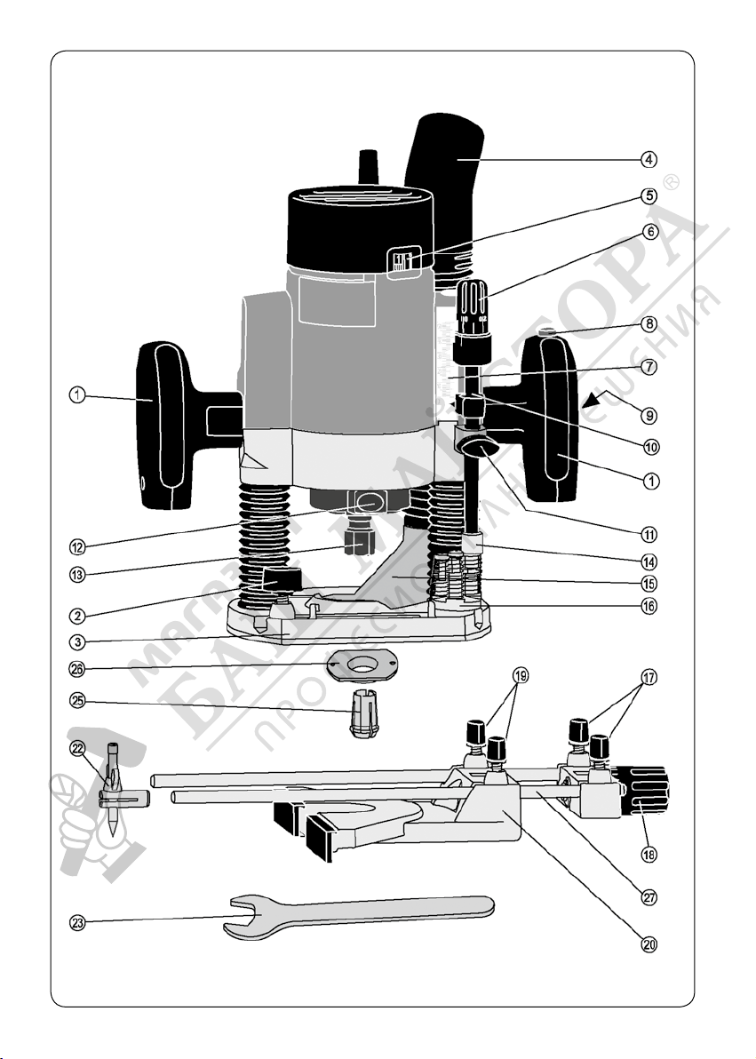
Fig. 1
39

Fig. 2
Fig. 4
40
Fig. 3
Fig. 5
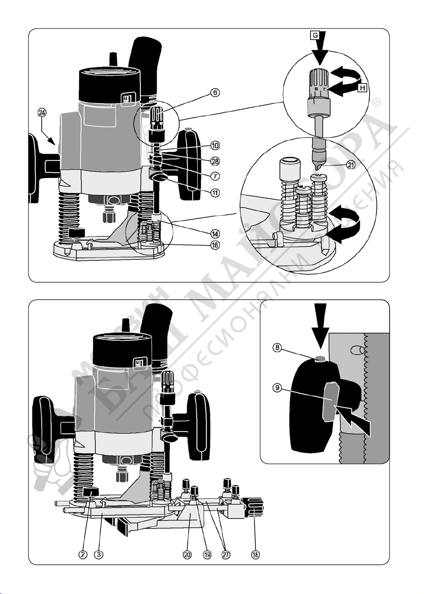
Fig. 6
Fig. 7
Fig. 8
41
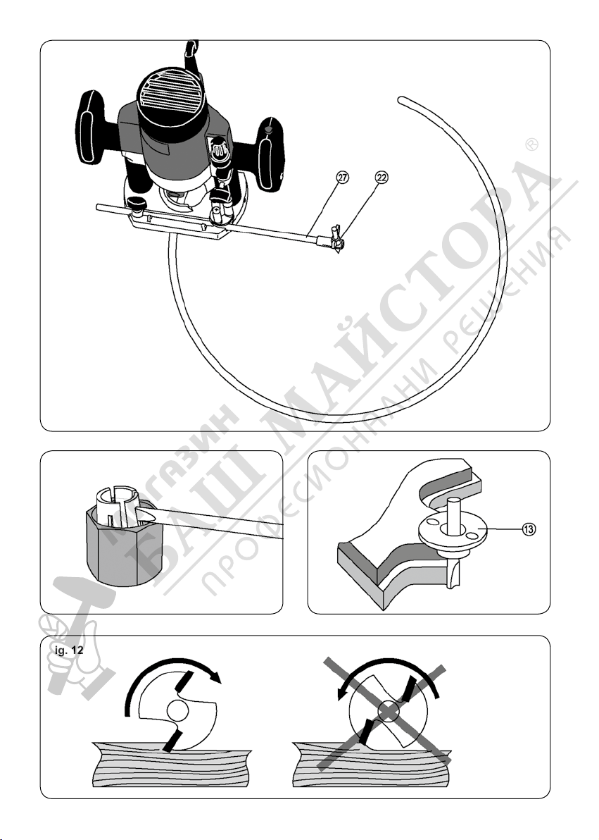
Fig. 9
Fig. 10 Fig. 11
Fig. 12
 Loading...