

Page 1
FR160P / FRE160P
Fresadora tupí
Router
Défonceuse
Tischfräsmaschine
Fresatrice toupie
Fresadora tupia
Ручной фрезер
Frezarka górnowrzecionowa
MANUAL DE INSTRUCCIONES
OPERATING INSTRUCTIONS
MODE D’ EMPLOI
GEBRAUCHSANWEISUNG
MANUALE D’ISTRUZIONI
MANUAL DE INSTRUÇÕES
ИНСТРУКЦИЯ ПО ЭКСПЛУАТАЦИИ
INSTRUKCJA OBSŁUGI
Page 2
7
sorios y embalajes de forma respetuosa con el medio
ambiente. Respete la normativa vigente de su país.
Aplicable en la Unión Europea y en países europeos
con sistemas de recogida selectiva de residuos:
La presencia de esta marca en el producto o en el
material informativo que lo acompaña, indica que
al finalizar su vida útil no deberá eliminarse junto
con otros residuos domésticos.
Conforme a la Directiva Europea 2002/96/CE los
usuarios pueden contactar con el establecimiento
donde adquirieron el producto, o con las autoridades
locales pertinentes, para informarse sobre cómo y
dónde pueden llevarlo para que sea sometido a un
reciclaje ecológico y seguro.
VIRUTEX se reserva el derecho de modificar sus
productos sin previo aviso.
ENGLISH
FR160P-FRE160P ROUTER
(Ilustrations in page 43)
Important
Read these OPERATING INSTRUCTIONS
and the attached GENERAL SAFETY
INSTRUCTIONS LEAFLET carefully
before using the machine. Make sure
you have understood them before ope-
rating the machine for the first time.
Keep both sets of instructions for any
future queries.
1. TECHNICAL DATA
FR160P
Universal motor.........................................50/60 Hz
Input power................................................1,500 W
No-load speed.......................................25,000/min
Chuck collet Ø.............................................12 mm
Routing depth............................................0-60 mm
Revolving depth
gauge.......................6-position depth adjustment
Weight...........................................................5.4 Kg
Weighted equivalent continuous
acoustic pressure level A............................................92 dBA
Acoustic power level A.............................................103 dBA
Uncertainty...........................................................K = 3 dbA
Wear ear protection!
Vibration total values.................................a
h
: <2.5 m/s
2
Uncertainty..........................................................K: 1.5 m/s
2
FRE160P
Universal motor..........................................50 Hz
Input power................................................1,800 W
No-load speed............................11,500-23,000/min
Chuck collet Ø.............................................12 mm
Routing depth............................................0-60 mm
Revolving depth
gauge.......................6-position depth adjustment
Weight...........................................................5.4 Kg
Weighted equivalent continuous
acoustic pressure level A............................................92 dBA
Acoustic power level A............................................103 dBA
Uncertainty.............................................................K = 3 dbA
Wear ear protection!
Vibration total values........................................a
h
: <2.5 m/s
2
Uncertainty............................................................K: 1.5 m/s
2
2. OPERATION RANGE
The router is an electric appliance used for routing
wood and plastics. It is also very convenient for
trimming edges, cutting out of knots, copy cutting,
rebate cutting, making of frames and engraving.
Together with parallel guide, template followers,
compasses and profile cutters, it is an exceedingly
useful appliance.
3. SAFETY INSTRUCTIONS FOR
MACHINE OPERATION
Before using the router, carefully read
the GENERAL SAFETY INSTRUCTIONS
LEAFLET included with the machine
documentation.
- When changing tools or carrying out any other
operation near the cutting head, take your hand
from the on/off lever and unplug the machine from
Page 3
8
the mains.
- Use safety goggles when working with the router.
- Always guide the router with both hands, using
the machine's two handles.
- When you have finished working, disconnect the
motor and release the base before leaving the router.
- Always place the router on its base on a flat, clean
surface.
- Always start the router by using the main on/
off lever.
- Make sure that the router cannot be accidentally
knocked over.
- Always use cutter bits with the appropriate shaft
diameter for the chuck collet and the router speed
to be used.
- The specifications of the cutter bits in the VIRUTEX
range are especially suitable for use with this router;
we recommend using cutter bits from the wide
VIRUTEX range or bits with the same specifications.
4. STANDARD EQUIPMENT
The box contains the following items:
- FR160P - FRE160P router
- A/f service key: 24
- Ø 19 mm template guide for 26-mm pitch loops.
- Lateral fence assembly
- Dust collector connection
- Operating instructions and miscellaneous docu-
mentation.
- 6022387 Cutter bit 12 to 8 adaptor
- 6022388 Cutter bit 12 to 6 adaptor
5. STARTING UP THE MACHINE
This tool has an operating switch A (Fig. 1) in the
handle, enabling the machine to be turned on and
off without releasing it.
To prevent the machine from starting up accidentally,
the switch can only be operated when the lateral
safety catch B (Fig. 3) has been released. Once the
switch is in the on position, pressure need no longer
be applied to the safety catch.
Always make sure that the router is
not in contact with the part being
worked before operating the switch.
Once the machine has reached its
maximum speed, bring the machine
into contact with the material, and
stop the machine once it is completely
clear of the part. This will improve the
quality of the work.
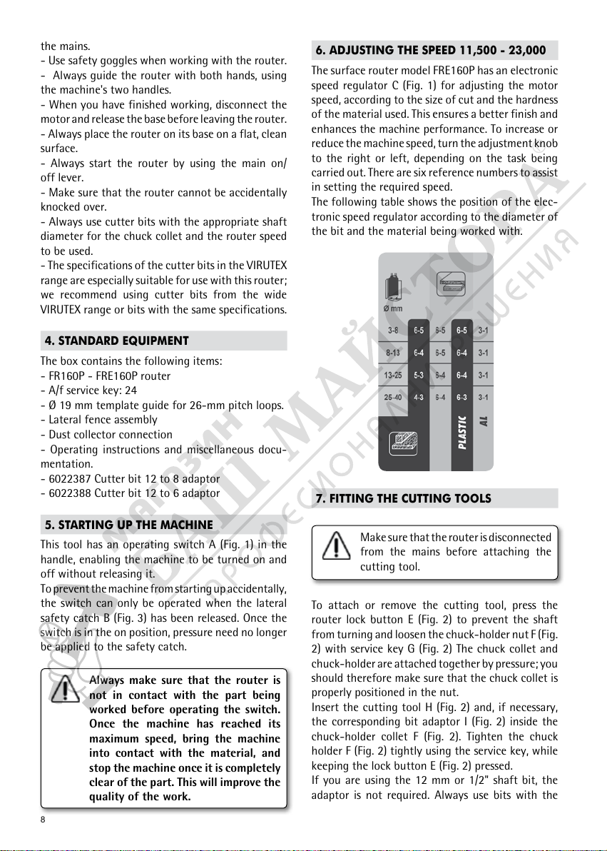
6. ADJUSTING THE SPEED 11,500 - 23,000
The surface router model FRE160P has an electronic
speed regulator C (Fig. 1) for adjusting the motor
speed, according to the size of cut and the hardness
of the material used. This ensures a better finish and
enhances the machine performance. To increase or
reduce the machine speed, turn the adjustment knob
to the right or left, depending on the task being
carried out. There are six reference numbers to assist
in setting the required speed.
The following table shows the position of the elec-
tronic speed regulator according to the diameter of
the bit and the material being worked with.
7. FITTING THE CUTTING TOOLS
Make sure that the router is disconnected
from the mains before attaching the
cutting tool.
To attach or remove the cutting tool, press the
router lock button E (Fig. 2) to prevent the shaft
from turning and loosen the chuck-holder nut F (Fig.
2) with service key G (Fig. 2) The chuck collet and
chuck-holder are attached together by pressure; you
should therefore make sure that the chuck collet is
properly positioned in the nut.
Insert the cutting tool H (Fig. 2) and, if necessary,
the corresponding bit adaptor I (Fig. 2) inside the
chuck-holder collet F (Fig. 2). Tighten the chuck
holder F (Fig. 2) tightly using the service key, while
keeping the lock button E (Fig. 2) pressed.
If you are using the 12 mm or 1/2" shaft bit, the
adaptor is not required. Always use bits with the
Page 4

9
shortest possible cutting length in order to reduce
the risk of the bit decentring. The bit, chuck collet
and adaptor should be completely clean before
attachment.
Do not leave the machine without a
cutting tool, as this exerts excessive
pressure on the chuck collet and can
damage the shaft housing.
Never start the machine while the bit
lock button is pressed.
8. BLOCKING OF THE BASE
The base may be locked in any position by turning
locking lever E (Fig. 3) in the counter-clockwise. The
action of the springs incorporated in the columns
means that when this lever is loosened the base
automatically returns to its highest position.
After use, always turn the switch to
the off position and release the base
using the locking lever J (Fig. 3) before
placing the router on a flat surface.
9. ADJUSTING THE DEPTH
ADJUSTING THE DEPTH. The depth is adjusted
by using the incorporated rack and pinion depth-
adjustment mechanism.
With the cutter bit face flush against the wood
surface, the penetration depth may be adjusted up
to 60 mm.
To unlock the depth rod K (Fig. 4) press down firmly
on adjustment knob L (Fig. 4) and turn it to raise or
lower the depth rod, if a greater or lesser cutting
depth is required. The gauged adjustment indicator
M (Fig. 4) can be moved separately from the knob, so
that it may be set to zero from any position using the
reference mark. When turning the knob after adjus-
ting the indicator, both elements will turn together,
there by indicating the degree to which the rod has
been moved. A full turn of the knob moves the rod
by 34 mm, with a maximum distance of 55 mm.
To hold the depth rod in the required position, release
the pressure from the adjustment knob. Next, to
ensure that the rod is firmly held in place, it should
be locked using fastening knob N (Fig. 4).
PRECISION ADJUSTMENT. If you wish to make
precision adjustments to the previously set depth,
simply turn adjustment knob O (Fig. 4). A full turn
of the knob moves the rod by 1 mm, with a maxi-
mum distance of 5 mm. Each division in the gauged
fine-adjustment indicator P (Fig. 4) represents an
advance of 0.1 mm.
MAKING DEEP CUTS. To safely make cuts that are
too deep to be made with a single pass, we recom-
mend making several successive cuts using the six
3-mm steps in the revolving depth turret Q (Fig. 4).
Lower the machine until the cutting bit is level with
the surface on which the router is resting. Use locking
knob J (Fig. 3) to hold the machine in this position.
Loosen fastening knob N (Fig. 4), then press down
and turn adjustment knob L (Fig. 4) until the depth
rod presses against the lower step of the revolving
depth turret, using fine adjustment if required. In
this position, turn depth indicator M (Fig. 4) until
position zero matches the reference mark. This
will be the starting position indicating the point at
which the bit comes into contact with the material.
Hold the rod in place with knob N (Fig. 4), release
the locking knob J (Fig. 3) and leave the machine in
the off position.
Loosen fastening knob N (Fig. 4), then press down
and turn adjustment knob L (Fig. 4), moving the
adjustment rod K (Fig. 4) upwards to the required cut
depth. Then use knob N once again to turn turret Q
(Fig. 4) until the highest step is below rod K (Fig. 4).
Make the first cut on the material. Turn the turret
Q to the next step and then make another cut, and
so on until the required depth is obtained when the
bottom step is reached.
10. LOCKING THE ROUTING DEPTH
To carry out several repetitive jobs in which the
router depth is always the same, it may be useful to
prevent the head from being released by accidentally
moving the locking knob J (Fig. 3). This may be done
by inserting two M8 nuts R (Fig. 3) in the threaded
shaft, one above and one below the head body. This
locks the head at any point along its depth setting.
When working with the router depth
locked, the tool will be permanently
outside the base surface. Therefore
the following actions must be taken:
- Wait until the machine has come to a complete stop
before setting it down on its base, on a flat surface,
with the cutting tool free.
- Remove nuts R (Fig. 3) to return to the normal
lock conditions using lever J (Fig. 3), once the job
is complete.
Page 5

10
11. USE OF PARALLEL GUIDE
The parallel guide is used for trimming edges and
cutting slots of different shapes, depending on the
profile shape. Hard metal cutter bits are particularly
useful for smoothing edges and lengthening the
working life of the bits.
The parallel guide S (Fig. 6) is inserted in the openings
on the base T (Fig. 6) and is held in place using the
two knobs U (Fig. 6).
NORMAL SQUARE ADJUSTMENT – Loosen the base
knobs U (Fig. 6), move the square to the required
position and then tighten the knobs in this position.
PRECISION ADJUSTMENT – Once the square has
been approximately positioned and held in place,
a further fine adjustment may be made. To do this,
loosen square fastening knob V (Fig. 6), turn the
adjustment knob W (Fig. 6) to the required measu-
rement, then tighten the square fastening knob V
(Fig. 6) again in this position. A full turn of the knob
moves the square by 1 mm, with a maximum distance
of 10 mm. The gauged fine-adjustment indicator X
(Fig. 6) can be moved separately from the knob, so
that it may be set to zero from any position using
the reference mark. When turning the knob W (Fig.
6) again after adjusting the indicator X (Fig. 6), both
elements will turn together, there by indicating the
degree to which the square has been moved, with
each division representing an advance of 0.1 mm.
12. USE OF TEMPLATE GUIDES
The template guides are used for routing with a wide
variety of shapes. The chosen template guide Y (Fig.
7) is held to the base T (Fig. 7) with the two screws Z
(Fig. 7). On making a copy, a difference between the
size of the template and the routed part will appear.
The difference between the radius of the template
guide and the cutting tool must always be taken into
account when making a template.
13. DUST COLLECTOR ATTACHMENT
To attach the dust collector connector A1 (Fig. 6),
place it in the central recess in base T (Fig. 6), with
the connection facing the back, and hold it in place
with screws B1 (Fig. 6). If trimming dovetails with the
Virutex PL11 model dovetailing attachment, guide
and position the dust collector connector as desired
so that the trimmer moves over the dovetailing
attachment better.
The dust collector connector A1 may be attached
either directly to the suction tubes of AS182K and
AS282K dust collectors, or else by using the smaller-
diameter and lighter 6446073 standard dust collector
attachment or 1746245 of 5 m, C1 (Fig. 6), which
can then be attached to AS182K and AS282K dust
collectors or any other industrial dust collector.
14. DUST COLLECTION NOZZLE SUPPLEMENT
To ensure that the suction of the machine is sufficient
when working with trimmer bits of less than 30 mm
in diameter, use the dust collection nozzle A1 (Fig. 6)
with the included supplement F1 (Fig. 6).
If you are using trimmer bits with a diameter of more
than 30 mm and up to 40 mm, remove the supplement
F1 (Fig. 6) from the dust collection nozzle A1 (Fig.
6) and work with only the nozzle. To re-attach the
supplement, simply press it firmly into the nozzle slot.
15. CHANGING THE BRUSHES
Make sure the machine is disconnected
from the mains before performing any
operation.
The brushes should be replaced when they have a
minimum length of 5 mm. To do this, remove the
covers D1 (Fig. 8) that hold the brushes E1 (Fig. 8) and
replace them with original VIRUTEX brushes, making
sure that they slide smoothly inside the guides.
It is advisable to allow the machine to run for 15
minutes unloaded after changing the brushes. When
changing the brushes, check the condition of the
collector. If it is burnt or juts out, it should be serviced
by a Virutex service technician.
16. LUBRITATION AND CLEANING
The machine is delivered fully lubricated from the
factory and does not require any special care during
its working life. It is important to clean the machine
carefully after use, using a dry air jet.
Maintain the supply cable in perfect operating
conditions.
17. OPTIONAL ACCESSORIES
The following optional accessories are available:
5000000 loop template PL11
6027103 Chuck collet Ø 12
6027106 Chuck collet Ø 1/2"
6022389 Cutter bit 1/2" to 3/8" adaptor
6022390 Cutter bit 1/2" to 1/4" adaptor
6446073 Standard dust collector attachment 2.25 m.
1746245 Dust collection connector 5 m
Page 6

11
Template guides:
7722168 Ø ext. 10 mm for 6 mm bits
7722120 Ø ext. 12 mm for 8 mm bits
7722121 Ø ext. 14 mm for 10 mm bits
7722122 Ø ext. 16 mm for 12 mm bits
7722169 Ø ext. 18 mm for 14 mm bits
7722118 Ø ext. 20 mm for 16 mm bits
7722119 Ø ext. 27 mm for 23 mm bits
7722114 Ø ext. 30 mm for 26 mm bits
Dovetail template guides:
7722161 For Ø 9.5 mm bit and 16 mm pitch plate
7722123 For Ø 15 mm bit and 26 mm pitch plate
7722162 For Ø 20 mm bit and 34 mm pitch plate
6040313 Carbide straight bit Ø 16
18. NOISE AND VIBRATION LEVEL
The noise and vibration levels of this device have
been measured in accordance with European stan-
dard EN 60745-2-17 and EN 60745-1 and serve as
a basis for comparison with other machines with
similar applications.
The indicated vibration level has been determined
for the device’s main applications and may be used
as an initial value for evaluating the risk presented
by exposure to vibrations. However, vibrations
may reach levels that are quite different from the
declared value under other application conditions,
with other tools or with insufficient maintenance
of the electrical device or its accessories, reaching a
much higher value as a result of the work cycle or
the manner in which the electrical device is used.
Therefore, it is necessary to establish safety measures
to protect the user from the effects of vibrations,
such as maintaining both the device and its tools
in perfect condition and organising the duration
of work cycles (such as operating times when the
machine is subjected to loads, and operating times
when working with no-load, in effect, not in use, as
reducing the latter may have a considerable effect
upon the overall exposure value).
19. WARRANTY
All VIRUTEX power tools are guaranteed for 12 months
from the date of purchase, exlcuding any domage
which is a result of incorrect use or of natural wear and
tear on the machine. All repairs should be carried out
by the official VIRUTEX technical assistance service.
20. RECYCLING ELECTRICAL EQUIPMENT
Never dispose of electrical equipment with domestic
waste. Recycle equipment, accessories and packaging
in ways that minimise any adverse effect on the
environment. Comply with the current regulations
in your country.
Applicable in the European Union and in European
countries with selective waste collection systems:
If this symbol appears on the product or in the ac-
companying information, at the end of the product's
useful life it must not be disposed of with other
domestic waste.
In accordance with European Directive 2002/96/EC,
users may contact the establishment where they
purchased the product or the relevant local authority
to find out where and how they can take the product
for environmentally friendly and safe recycling.
VIRUTEX reserves the right to modify its products
without prior notice.
FRANÇAIS
DÉFONCEUSE FR160P-FRE160P
(Figures en page 42)
Important
Avant d'utiliser la machine, lisez atten-
tivement ce MANUEL D'INSTRUCTIONS
et la BROCHURE D'INSTRUCTIONS
GÉNÉRALES DE SÉCURITÉ qui vous sont
fournis avec cette machine. Assurez-
vous de bien avoir tout compris avant de
commencer à travailler sur la machine.
Gardez toujours ces deux manuels
d'instructions à portée de la main pour
pouvoir les consulter, en cas de besoin.
1. DONNÉES TECHNIQUES
FR160P
Moteur universel........................................50/60 Hz
Puissance..................................................1.500 W
Vitesse à vide......................................25.000/min
Diamètre pince standard...............................12 mm
Profondeur de fraisage..............................0-60 mm
Page 7

Fig. 1
Fig. 2
Fig. 3
Fig. 5
Fig. 4
Fig. 6
42
Page 8

Fig. 7
Fig. 8
43
Page 9

Virutex, S.A.
Antoni Capmany, 1
08028 Barcelona (Spain)
www.virutex.es
6096443 102016
http://www.virutex.es/registre
Acceda a toda la información técnica.
Access to all technical information.
Accès à toute l’information technique.
Zugang zu allen technischen Daten.
Accedere a tutte le informazioni tecniche.
Aceso a todas as informações técnicas.
Dostęp do wszystkich informacji technicznych.
Доступ ко всей технической информации.
 Loading...