

Page 1

OPERATING INSTRUCTIONS
MANUAL DE INSTRUCCIONES
FR129 VB
Router for fitting hinges
Fresadora de herrajes
Page 2
OPERATING INSTRUCTIONS
MANUAL DE INSTRUCCIONES
page/
página
ENGLISH FR129 VB Router for fitting hinges
ESPAÑOL Fresadora de herrajes FR129 VB
ENGLISH
ROUTER FOR FITTING HINGES FR129 VB
Important note
Carefully read the GENERAL SAFETY INSTRUCTION LEAFLET enclosed with the machine
documents.
Keep both sets of instructions for any future
queries.
Important note
Carefully read the GENERAL SAFETY INSTRUCTION LEAFLET enclosed with the machine
documents.
1. Before plugging in the machine, make sure that the
power supply voltage is the same as that shown on the
specifications plate.
2. Always keep hands clear of the cutting area. Always
hold the machine safely.
3. Always use original VIRUTEX tools. Never use defective
or damaged tools.
4. Always use cutter bits with the appropriate stem diameter
for the chuck collet and tool speed to be used.
2
6
Uncertainty......................................................................K = 3 dBA
Wear ear protection!
Vibration total values...............................................ah: < 2.5 m/s
Uncertainty...................................................................K: 1.5 m/s
Chuck diameter.................................................1/4" mm
Weight..............................................................5 kg=11 lbs
2. SPECIFICATIONS
Lengthways displacement of milling cutter shaft
5-3/4" = 145 mm
Sideways displacement of milling cutter shaft
2-1/8" = 54 mm
Lengthways milling with cutter bit Ø 1":
6-1/4" = 161 mm
Sideways milling with cutter bit Ø 1":
2-3/4" = 70 mm
Minimum opening between clamp vises
1-3/4" = 33 mm
Maximum opening between clamp vises
10" = 250 mm
Cutter bit maximum diameter
1" = 26 mm
Maximum milling depth
1/2" = 11 mm
Maximum milling depth (with kit for concealed hinges)
1-1/2" = 40 mm
2
2
Unplug the machine from the mains before
carrying out any maintenance operations.
1. CHARACTERISTICS
Power...........................................................1,000 W
No load speed.....................................14,000-27,000/min
Weighted equivalent continuous
acoustic pressure level A.................................................86 dBA
Acoustic power level A.........................................................97 dBA
2
The following concepts are dealt with in the different
sections of this manual. Please see (Fig. 1).
A = Width of rebate
B = Width of hinge wing
R = Depth of rebate (Interior side of rebate)
Right opening door
Left opening door
The FR129 VB router enables you to make recesses for
Page 3

rectangular hinges without using a template.
The corners of the recesses will have radius R (Fig. 15a) of
the TCT bit used. This means that if the original ½" TCT
bit is used, the radius will be ¼".
If you wish to fit hinges without a radius in the corners,
we have an optional accessory, "90° corner chisel 2945471"
(Fig. 15b). This will enable you to cut the radiuses with
maximum ease.
The FR129 VB router will also enable you to make recesses
for hinges of any shape, provided a suitable template is used.
Minimum recess required A (Fig. 1) for fitting hinges with
the FR129 VB using a template should be at least the same
width as hinge wing B +15/64"= 6 mm.
Templates for special hinges are manufactured in accordance with the width of the rebate and not the thickness
of the door, although both measurements are normally
the same, unless otherwise requested in the order form.
If the thickness of the door is less than the width of the
rebate, the hinge will fit correctly into the frame. However,
the hinge cylinder will project from the door face by the
difference in the two thicknesses.
3. UNPACKING
Inside the transporting case the following items will be
found: (Fig. 2)
1. Copy router model FR129 VB with hard metal bit Ø ½"
2. Base (without template)
3. Hinge distributor tube for three-hinge door
4. Hinge distributor connector for three-hinge door
5. Hinge distributor tube for four-hinge door
6. Hinge distributor connector for four-hinge door
7. Philips screwdriver.
8. 3/4"=19-mm wrench for chuck securing nut
9. 7/16"=11-mm wrench for blocking motor axle and
securing pointers
10. 5/32"=4-mm Allen wrench for adjusting frame/door
gap
door, and which enables motor body 1 (Fig. 3) to move on
guides, sideways lengthways and inwardly, to perform the
milling of the recess, and upon which template D can be
mounted (Fig. 7) if so desired, for milling hinge recesses.
This base 2 (Fig. 3) enables you to place the recesses for
the hinges on the frame, placing it on the width of the
rebate (Fig. 1 and 4), and stopping it on inner face R (Fig.
1), or on the edge of the door (Fig. 13).
It is also possible to fit hinges to doors without rebates,
taking the reference from the outer frame face with screws
C1 (Fig. 17), as explained in Section 10.
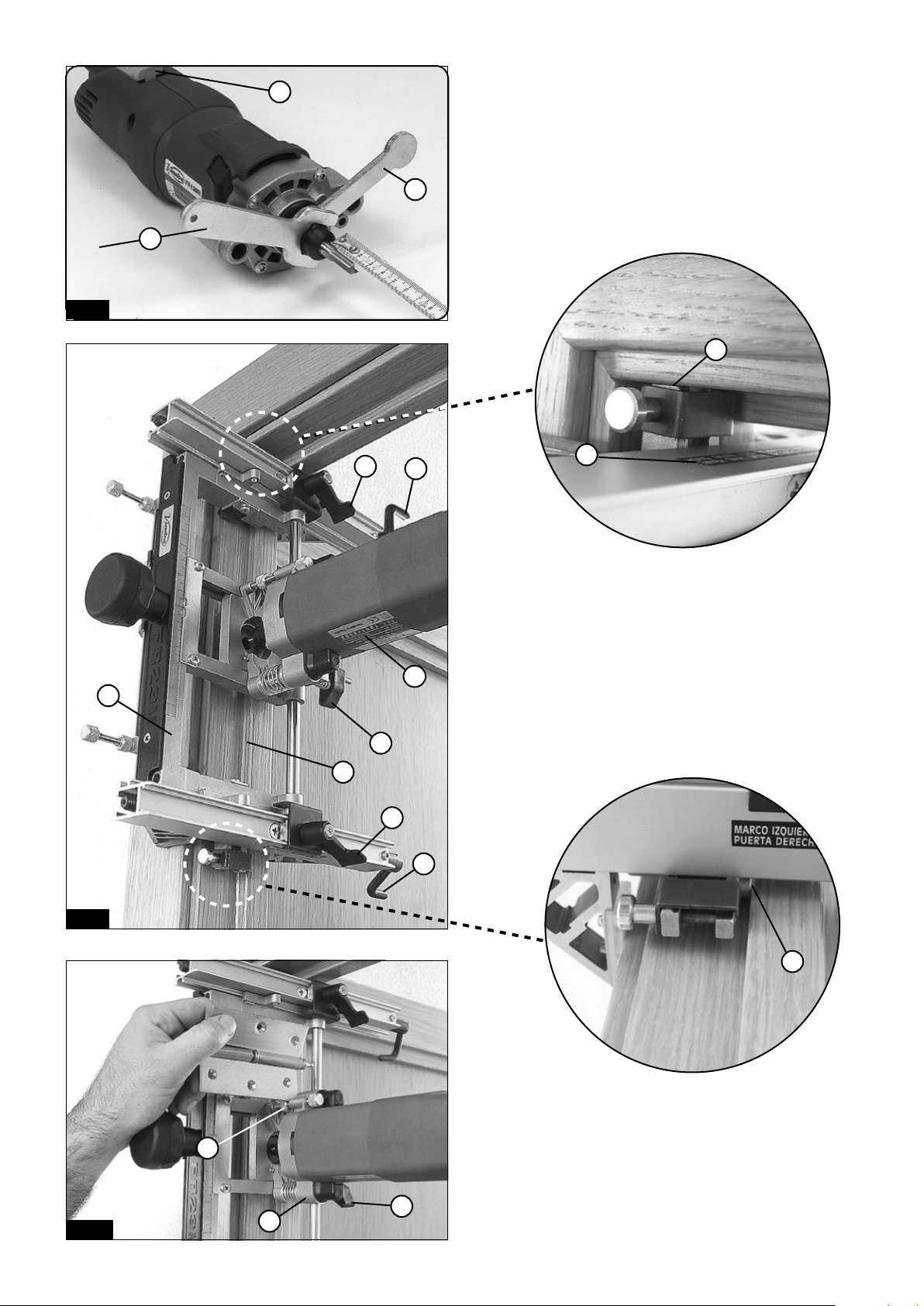
Base 2 (Fig. 4) is secured to the frame or door by tightening
clamp vises E (Fig. 4), by turning crank handles F (Fig. 4).
Base 2 (Fig. 5) of the machine has supports on either
side, G and H (Fig. 5), with the dual function of being
used for the outer face as a reference for the limit of the
lengthways recess of the frame (Fig. 9), to place the first
hinge, and as support for connector I (Fig. 3) and hinge
distributor tube K (Fig. 3), which are used for placing the
second and subsequent hinges.
Connector 1 (Fig. 3) has fitted stop J (Fig. 13), and this is
used to place the first hinge at the door. This stop comes
already regulated from the factory so that when the door
is hung to the frame there is a gap between the door and
the frame cross beam of approximately 1/16"=1.5 mm.
This gap can be widened if so desired by loosening screw
J1 (Fig. 13) and moving stop J (Fig. 13).
Hinge distributor tubes K (Fig. 3) enable the three or four
recesses to be placed along the length of the door and
frame (Fig. 11 and 14), and have regulators at each end.
These allow work to be done at different heights of the
door (6' 6", 6' 8", 7', 8' and 9'), and hinges (3", 3
½
", 4",
4½", 5" and 5 ½") (Fig. 3). The base has springs L (Fig. 6 and
7) for quick assembly of template D (Fig. 6 and 7) for the
hinge to be used.
6. PREPARATION OF THE ROUTER
4. ASSEMBLY OF THE ROUTER
Remove bolt C (Fig. 2).
Fit motor body 1 (Fig. 2) in the columns on router base
2 (Fig. 3).
Check the vertical movement of the motor body in the
columns.
Secure bolt C (Fig. 3).
Check that the template guide moves freely lengthways
and sideways in the template shape.
5. GENERAL DESCRIPTION OF THE MACHINE
The router for fitting hinges is made up of the following
components and performs the following tasks:
5.1 Motor body 1 (Fig. 3), which, via the motor axis, supplies the necessary power and revolutions to the TCT bit
to perform recessing.
5.2 Base 2 (Fig. 3), which includes the components for
securing and regulating the machine on the frame and
Ensure that the machine is disconnected from
the mains before carrying out any preparation
or maintenance work.
6.1 FITTING THE CUTTER BIT
Firstly remove the motor body 1 from the template base
2 (Fig. 2) following the instructions in section 4 in reverse
order. Using service keys 8 and 9 (Fig. 8) we can change
the bit if necessary and also adjust the outlet to 1
9/64"
=29
mm between the end of the bit and the side of the bolt,
taking care to secure it tightly.
Lastly the motor body is refitted to the base 2 (Fig. 3) as
indicated in section 4.
6.2 FITTING THE DISTRIBUTION TUBE
Hinge distributor tube 3 or 5 (Fig. 2) must be mounted
on connector 4 or 6 (Fig. 2) as shown in (Fig. 3), on the
corresponding drill hole at the height of the frame in
3
Page 4

which hinges 6' 6", 6' 8", 7', 8' or 9' (Fig. 3), are going to
be fitted.
At the opposite end of tube K (Fig. 3), place reference
stop M (Fig. 3) in the corresponding drill hole for the
length of hinge to be fitted, or in the nearest if it does
not correspond with that of those marked.
7. PLACING HINGES WITHOUT TEMPLATE ON
RIGHT HAND DOOR
7.1 PLACING HINGES ON THE FRAME
Ensure that the operations of fitting or adjusting the bit,
the template and the distribution tube indicated in section
6 have been fully carried out before proceeding.
ADJUSTING THE RECESS HEIGHT
The machine has stop ruler M (Fig. 15 and 7), with two
scales marked from the centre towards the two ends, (Fig.
15 and 7). Place the two stops A1 (Fig. 15 y 7) here in the
position corresponding to the height (3", 3
½
", 4", 4 ½",
5" or 5 ½") of the hinge we are about to fit.
POSITIONING THE MACHINE FOR THE FIRST RECESS
Loosen levers S (Fig. 9). Place the machine (Fig. 9) over the
rebate of the frame, turning the indicator "RIGHT FRAME"
MD (Fig. 9 and 5) towards the upper part of it.
Move the machine sideways to the end of the frame rebate
and upwards until support H (Fig. 9) touches the bottom
of the rebate in the crossbeam of the frame.
Tighten the clamp vises over the thick part of the doorframe by means of crank handles F (Fig. 9).
Move machine base 2 (Fig. 9) along the width of the rebate until it reaches interior face T (Fig. 9) of the rebate
on the frame. Secure the machine in this position using
levers S (Fig. 9).
ADJUSTING THE WIDTH OF THE RECESS
The width of the recess is obtained by regulating stop bolt
B1 (Fig. 16). Follow these steps:
Ensure that the machine has been disconnected from
the mains.
Hold the bit so that it touches the edge of the frame with
cutting edge Q (Fig. 15). Lock it into this position with
knob U (Fig. 16). Place stop bolt B1 at distance X (Fig. 16)
of fixed stop B2 (Fig. 16), equal to the width of the recess
you wish to make. The width stop will now be adjusted.
AJUSTING THE DEPTH OF THE RECESS
Push the motor body towards the frame until the bit tip
is touching the wood. Lock it into this position with knob
U (Fig. 9).
Place the hinge between head V and nut W (Fig. 10). Adjust
the width of the hinge with this bolt.
Remove the hinge and release knob U (Fig. 9).
STARTING UP THE MACHINE
To start the machine, press button X forward (Fig. 8) to the
on position. To stop the machine, simply press the back of
the switch and it will return to the off position.
4
ROUTING THE FIRST RECESS
By gradually pushing motor body 1 (Fig. 9), the bit will
make an incision on the frame to the depth of the previously adjusted hinge. Secure the machine at this depth
with knob U (Fig. 9).
Next, move the motor body lengthways and sideways,
between the adjusted stops until obtaining a recess for
the whole shape of the hinge. Once the recess for the first
hinge has been obtained, stop the machine. Loosen crank
handles F (Fig. 9), slide the machine to the approximate
position for the second hinge and once again secure crank
handles F.
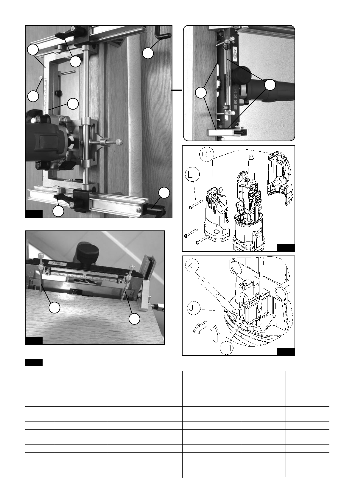
FITTING THE DISTRIBUTOR TUBE
Slightly loosen upper crank handle FS (Fig. 11) and separate
the machine from the frame on this side by approximately 13/64"=0.5 cm to facilitate the fitting of previously
prepared distributor tube K (Fig. 11).
Fit distributor tube K (Fig. 11) to support H (Fig. 11 and
5). To do this, pull pin G1 (Fig. 5) until connector I (Fig. 5)
of distributor tube K (Fig. 11) can enter between supports
H (Fig. 11 and 5). Release it when drill coincides with pin
G1 (Fig. 5) to bring about the locking.
ROUTING THE SECOND AND THIRD RECESSES
To position the machine for the second recess, loosen both
crank handles F (Fig. 11), place centring device M (Fig. 11)
of hinge distributor tube K (Fig. 11) on the bottom part
of the recess of the first hinge and, leaning the machine
against the recess, secure crank handles F (Fig. 11) once
again in this position.
Rout the second hinge recess in the same way as explained
for the first. This process is repeated to rout the third recess,
positioning distributor tube K (Fig. 11) over the second
hinge. This operation is repeated for the fourth if working
with distributor tube 5 (Fig. 2) for four hinges.
7.2 PLACING THE HINGES ON THE DOOR
FITTING THE DISTRIBUTOR TUBE
Fit hinge distribution tube K (Fig. 13) with stop J (Fig. 13)
facing downwards, into support G (Fig. 13) on the side
of the support marked "RIGHT HAND DOOR" MI (Fig. 13).
Secure it with pin G1 (Fig. 13).
MACHINE POSITION FOR THE FIRST RECESS
Loosen levers S (Fig. 13) and position the machine on the
edge of the door, with tube K (Fig. 13) towards the upper
side of it.
Move the machine along the edge of the door until stop
J (Fig. 13) touches the upper end of it. Tighten the clamp
vises to the door using crank handles F (Fig. 13). Move base
2 of the machine (Fig. 12 and 13) until stops Y (Fig. 12) on
either side of the base touch the heads of screws Z (Fig.
12). Secure levers S (Fig. 13) once again in this position.
The position of screws Z (Fig. 12) with respect to stops Y
(Fig. 12) provide a 1/16"=1.5 mm space in the hung door
between the entrance face of the door and the interior
Page 5

side of the rebate. If less space is required, screws Z can be
supplemented with washers of the required thickness.
THE MACHINE and PREPARING THE DISTRIBUTOR TUBE
have been completed, as explained in Section 6.
ROUTING THE FIRST RECESS
Connect the machine to the mains. Push safety button X
(Fig. 8), and press the switch to start the machine.
By gradually pushing motor body 1 (Fig. 13), the machine
will make an incision on the frame to the depth of the
previously adjusted hinge. Secure the machine at this
depth with knob U (Fig. 13). Next, move the motor body
lengthways and sideways, between the adjusted stops, until
obtaining the recess for the whole shape of the hinge.
Once the recess for the first hinge has been obtained, stop
the machine and loosen knob U (Fig. 13).
CHANGING THE DISTRIBUTOR TUBE
Remove distributor tube K (Fig. 13) from support G (Fig.
13) and fit it again to the same support. However this time
place stop J (Fig. 13 and 14) facing upwards.
ROUTING THE SECOND AND THIRD RECESSES
Loosen both crank handles F (Fig. 13), releasing the pressure
on the door thickness, and slide the milling machine to
the position of the second hinge.
The distance between hinges (Fig. 14) is obtained by positioning centring device M (Fig. 14) of hinge distributor
tube K (Fig. 14) over the lower part of the recess of the
first hinge. This leaves the machine at the exact distance
required for carrying out the recess for the second hinge.
Secure the ensemble to the door with crank handles F
(Fig. 14) in the same way as the first hinge, and rout the
recess accordingly. This process is repeated to rout the
third recess, positioning distributor tube K (Fig. 14) over
the second hinge. The operation is repeated for the fourth
if working with tube 5 (Fig. 2) for 4 hinges.
8. PLACING HINGES ON LEFT-HAND DOORS,
WITHOUT A TEMPLATE
8.1 PLACING THE HINGES ON THE FRAME
The process to follow for routing the recesses is the same
as that for the frames for right-hand doors, the only difference being that support G (Fig. 5) must be used, from
the side of the base marked "LEFT-HAND FRAME" MI, as
a reference for locating the first hinge in the frame and
for mounting distributor tube K in it. This is also used for
successive ones (Fig. 5).
8.2. PLACING THE HINGES IN THE DOOR
The process to follow for milling the recesses is the same
as that for the frames for right-opening doors, the only
difference being that support H (Fig. 5) must be used marked "LEFT-HAND DOOR" MD (Fig. 5) - for mounting
distributor tube K, used for placing the recesses (Fig. 5).
9. MAKING RECESSES WITH A TEMPLATE
Before continuing, ensure that MOUNTING OR REGULATING
PREPARING THE TEMPLATE AND TEMPLATE GUIDE
If planning to use the ½" bit supplied with the machine,
fit template guide outside diameter 16, N (Fig. 7) in the
machine with 2 screws in drill hole N1 (Fig. 7).
Place stops A1 (Fig. 7) and B1 (Fig. 16) at the maximum
distance so that they will not work when copying with
the template.
Template D (Fig. 6 and 7) will be needed for fitting every
type of hinge. This same template works for placing the
hinge in the frame and door, regardless of whether these
are right or left opening.
Template D (Fig. 7) is pressure-locked onto springs L. The
arrow of the template must be aligned with the instruction "RIGHT-DERECHA" (Fig. 6) of the side of the base, if
preparing the machine for right opening doors, or with
the instruction "LEFT-IZQUIERDA", on the opposite side,
for left opening doors.
Check to ensure the free lengthways and crossways movement of the template guide within the template shape.
For hinges whose frame-fastening wings end in a rounded
tip, we recommend using a bit with the same diameter as
the width of this wing, and the template guide corresponding to the bit. In this way, the recess is made in one
go and with greater speed. See the section on bits and
template guides (Fig. 21).
POSITIONING THE MACHINE FOR MAKING RECESSES,
ADJUSTING THE DEPTH OF RECESS AND FITTING THE DISTRIBUTOR TUBE, in the door or frame and for right or left
opening doors, is done just as if one was working without
a template, as explained in sections 7 and 8 of this manual.
When MAKING RECESSES, instead of moving the machine
between the stops, move it along the inside of the template
until copying the template shape in the recess.
10. PLACING HINGES LEVEL WITH THE EXIT FACE,
OR IN FRAMES WITHOUT REBATE, WITH OR WITHOUT TEMPLATE
To place hinges in frames without rebates, or in frames with
recesses larger than the template that is available and/or
in those where one wants the door to fit flush with the
frame on the exit face, the machine has two adjustable
stops C1 (Fig. 17 and 18), which enable the machine to
be positioned in the frame on the external face of it (Fig.
17) and on the door on the exit side of it (Fig. 18), instead
of positioning it by the frame rebate and the entry face
of the door, as in the standard process which has been
explained.
The process for making the recesses is identical to that
explained in sections 7 and 8 of this manual except with
regard to the MACHINE POSITION FOR THE FIRST RECESS:
where in the frame, instead of moving the base of milling
machine 2 (Fig. 17) along the width of the rebate until it
stops with the interior face of it, the position of the hinge
5
Page 6

has to be adjusted with respect to the frame with screws
C1 (Fig. 17). Secure them with bolts D1 (Fig. 17), and secure
the base in this position with levers S (Fig. 17).
Once adjusted for the frame, adjustable stops C1 (Fig. 17
and 18) can also be used to position the machine in the
door, but, unlike the standard process (Fig. 18), using the
exit side.
11. RECOMMENDATIONS
Use the templates which correspond to the shapes and
sizes of the hinges to be placed.
Use suitable bits and the corresponding template guides
for the diameter of the bit.
12. MAINTENANCE
The noise level in the workplace could go over 85dB(A).
In this case it is necessary for the user to wear noise
protection.
16. GUARANTEE
All of VIRUTEX portable tools are guaranteed for 12 months
from the date of supply, excluding any damage which is
a result of incorrect use or of natural wear and tear on
the machine.
All repairs should be carried out by the official VIRUTEX
technical assistance service.
VIRUTEX reserves the right to modify its products without
prior notice.
12.1 BRUSHES AND COLLECTOR
Unplug the machine from the mains before
carrying out any maintenance operations.
Remove the screws E1 (Fig. 19) that hold the side covers
G1 and detach them.
Remove the brush-holder J1 (Fig. 20) with small screwdriver K1, using one of the brush-holder side tabs to lever
it out.
Push back the end of spring F1. Keep it in this position to
extract the brush and replace it with a new genuine VIRUTEX
brush. Reinsert the brush-holder, ensuring that it is firmly
positioned in the casing and that each of the brushes exerts
a small amount of pressure on the collector.
Re-attach the covers G1 with the corresponding screws,
making sure that no wires get caught in the process.
It is advisable to leave the machine running for 15 minutes
once the brushes have been changed.
If the collector burns or juts out, it should be serviced by
a VIRUTEX service technician.
To ensure that mobile parts continue to move correctly,
remember to get rid of any dirt, dust and shavings produced when making recesses.
Keep the cable and plug in good service condition.
13. ACCESSORIES
Standard templates for different hinges
Template guides for different bit diameters.
2945471 - 90° CORNER CHISEL RC29M
1222024 - CHUCK COLLET Ø 8 mm
14. TEMPLATE GUIDES AND CORRESPONDING
BITS
See (Fig. 21)
15. NOISE LEVEL
These levels have been measured according to the European
Standard EN50144.
6
ESPAÑOL
FRESADORA DE HERRAJES FR129 VB
Nota importante
Lea atentamente el FOLLETO DE INSTRUCCIONES GENERALES DE SEGURIDAD que se adjunta con la documentación de la máquina.
Conserve los dos manuales de instrucciones
para posibles consultas posteriores.
Nota importante
Lea atentamente el FOLLETO DE INSTRUCCIONES GENERALES DE SEGURIDAD que se adjunta con la documentación de la máquina.
1. Asegúrese antes de enchufar la máquina, que la tensión
de alimentación se corresponda con la indicada en la chapa
de características.
2. Mantenga siempre las manos alejadas del área de corte.
Sujete siempre con la seguridad la máquina.
3. Use siempre herramientas originales VIRUTEX. No use
nunca herramientas defectuosas o en mal estado.
4. Utilizar siempre fresas con el diámetro de la caña adecuado a la pinza a utilizar y adaptadas a la velocidad de
la herramienta.
Desconectar la máquina de la red eléctrica
antes de proceder a cualquier operación de
mantenimiento.
1. CARACTERÍSTICAS
Potencia.................................................................1.000 W
Velocidad en vacío..................................14.000-27.000/min
Nivel de Presión acústica Ponderado A................86 dBA
Nivel de Potencia acústica Ponderada A..........97 dBA
Page 7

Incertidumbre de la medición........................K = 3 dBA
¡Usar protectores auditivos!
Nivel total de emisión de vibraciones......a
: <2,5 m/s
h
Incertidumbre de la medición.........................K: 1,5 m/s
2
2
Diámetro pinza......................................................1/4"
Peso.................................................................5 kg=11 lbs
2. DIMENSIONES
Desplazamiento longitudinal del eje de la fresa
5-3/4" = 145 mm
Desplazamiento transversal del eje de la fresa
2-1/8" = 54 mm
Fresado longitudinal máx. con fresa Ø 1":
6-1/4" = 161 mm
Fresado transversal máx. con fresa Ø 1":
2-3/4" = 70 mm
Abertura mínima entre las mordazas
1-1/4" = 33 mm
Abertura máxima entre las mordazas
10" = 250 mm
Diámetro máximo de fresa
1" = 26 mm
Profundidad máxima de fresado
1/2" = 11 mm
Profundidad máxima de fresado (con kit de bisagras
invisibles)
1-1/2" = 40 mm
En éste manual, se citan en distintos apartados, los conceptos que a continuación se detallan y cuya interpretación
encontrará en la (Fig. 1)
A = Ancho de rebajo.
B = Ancho de la pala del pernio o bisagra
R = Profundidad de rebajo (cara interior del rebajo)
Cara de entrada de la puerta
Cara de salida de la puerta
Puerta de apertura derecha
Puerta de apertura izquierda
Con la fresadora FR129 VB pueden realizarse sin plantilla,
encajes para bisagras y pernios rectangulares.
Las esquinas de los encajes realizados, quedarán con el
radio R (Fig. 15a) de la fresa que emplee, que será de 1/4"
si usa la fresa de origen de 1/2".
Si encaja bisagras sin radio en las esquinas, disponemos
de un accesorio opcional; "Recortador de esquinas a 90°
2945471" (Fig. 15b), con el que podrá recortar los radios
muy fácilmente.
También pueden realizarse con la fresadora FR129 VB,
encajes para pernios o bisagras de cualquier forma, usando
la plantilla adecuada.
Para poder encajar pernios o bisagras con la FR129 VB
con plantilla, el ancho mínimo necesario de rebajo A (Fig.
1), debe ser al menos igual al ancho de pala del pernio o
bisagra B+15/64"=6 mm.
Las plantillas para pernios o bisagras especiales, se fabrican
siempre, de acuerdo al ancho del rebajo y no al grueso de
la puerta, aunque ambas medidas suelen coincidir, a menos
que se solicite lo contrario expresamente en el pedido. Si el
grueso de la puerta, es menor, que el ancho del rebajo, el
pernio o bisagra quedará bien colocado en el marco, pero
en la puerta, el cilindro del pernio o bisagra sobresaldrá de
la cara de la puerta, la diferencia entre los gruesos.
3. DESEMBALAJE
En el interior de la maleta de transporte, Ud. encontrará
los elementos siguientes: (Fig. 2)
1. Fresadora copiadora modelo FR129 VB con fresa Ø: 1/2"
de Metal Duro.
2. Conjunto base fresadora (sin plantilla)
3. Tubo distribución de bisagras o pernios para 3 bisagras
por puerta.
4. Conector distribuidor bisagras o pernios para 3 bisagras
por puerta.
5. Tubo distribución de bisagras o pernios para 4 bisagras
por puerta.
6. Conector distribuidor bisagras o pernios para 4 bisagras
por puerta.
7. Destornillador Philips
8. Llave e/c 3/4"=19 mm para tuerca fijación pinza.
9. Llave e/c 7/16"=11 mm para bloquear eje motor y fijar
índices.
10. Llave e/c 5/32"= 4 mm para ajustar holgura marco/
puerta.
4. ENSAMBLAJE DE LA FRESADORA
Desenroscar la tuerca C, (Fig. 2).
Montar el cuerpo motor 1 (Fig. 2), en las columnas del
bastidor de la fresadora 2, (Fig. 3).
Comprobar el deslizamiento vertical del cuerpo motor en
sus columnas.
Enroscar la tuerca C (Fig. 3).
Comprobar el libre desplazamiento longitudinal y transversal.
5. DESCRIPCIÓN GENERAL DE LA FRESADORA
Los elementos integrantes de la fresadora y sus funciones
son los siguientes:
5.1 Un cuerpo motor 1 (Fig. 3), el cual, a través de su eje
motor, suministra la potencia y revoluciones necesarias a
una fresa para realizar los encajes.
5.2 Un bastidor 2 (Fig. 3), que incorpora los elementos de
fijación y regulación, al marco y la puerta, que permite
el desplazamiento del cuerpo motor 1 (Fig. 3) sobre unas
guías, en los sentidos longitudinal, transversal y de profundidad, para obtener el fresado del encaje, y en el que
puede montarse si se desea una plantilla D (Fig. 7) para
fresar encajes de pernios. Este bastidor 2 (Fig. 3), permite
situar los encajes para las bisagras o pernios en el marco, colocándola sobre el ancho del rebajo (Figs. 1 y 4), y
7
Page 8

haciendo tope en la cara interior R (Fig. 1) del mismo, o
sobre el canto en la puerta, (Fig. 13).
También es posible el encaje de bisagras o pernios en
marcos sin rebajo, referenciando por la cara exterior del
marco con los tornillos C1 (Fig. 17), como se explica en
el apartado 10.
El bastidor 2 (Fig. 4), se fija sobre el marco o la puerta,
mediante el apriete de las mordazas E (Fig. 4), al girar las
manivelas F (Fig. 4).
El bastidor 2 (Fig. 5) de la fresadora dispone en cada lateral
de unos soportes, G y H (Fig. 5), con la doble función de
servir por su cara exterior, de tope de referencia sobre el
rebajo del travesaño del marco (Fig. 9), para situar la primera
bisagra o pernio y de soporte para el conector I (Fig. 3) y el
tubo distribución pernios K (Fig. 3), que se emplean para
situar la segunda bisagra o pernio y los sucesivos.
El conector I (Fig. 3), lleva montado el tope J (Fig. 13), que
se emplea para situar la primera bisagra en la puerta. Este
tope sale regulado de fábrica para que una vez colgada
la puerta, quede una holgura entre ésta y el travesaño
del marco de aproximadamente 1/16"=1.5 mm. Puede
aumentar esta holgura si lo desea, aflojando el tornillo
J1 (Fig. 13) y desplazando el tope J (Fig. 13).
Los tubos distribución pernios K (Fig. 3), permiten repartir
los tres o cuatro encajes, en la longitud del marco y de
la puerta, (Figs. 11 y 14), y llevan regulaciones en sus dos
extremos, que permiten trabajar sobre distintas alturas de
puerta, 6' 6", 6' 8", 7', 8' y 9', y de bisagra 3", 3
1/2
", 5" y 5
1/2
" (Fig. 3). El bastidor dispone de un dispositivo
1/2
", 4", 4
L (Fig. 6 y 7), para el ensamblaje rápido de la plantilla D
(Fig. 6 y 7), del pernio a utilizar.
6. PREPARACIÓN DE LA FRESADORA
Asegúrese que la máquina está desconectada
de la red eléctrica, antes de realizar cualquier
operación de preparación o mantenimiento
de la misma.
6.1 MONTAJE DE LA FRESA
Extraer previamente el cuerpo motor 1 (Fig. 2 ), del bastidor
2 (Fig. 3), procediendo en sentido inverso al explicado en
el apartado 4, para su montaje. Con la ayuda de las llaves
de servicio 8 y 9, (Fig. 8), cambiar la fresa si es necesario
y regular la salida de la misma, a 1
9/64"
=29 mm entre el
extremo de la fresa y la cara de la tuerca, y asegurarse de
que quede firmemente apretada.
Para terminar, proceda de nuevo al montaje del cuerpo
motor 1, en el bastidor 2 (Fig. 3), como se indica en el
apartado 4.
6.2 PREPARACION DEL TUBO DISTRIBUIDOR
El tubo distribuidor de bisagras o pernios 3 o 5 (Fig. 2), debe
montarse sobre el conector 4 o 6 (Fig. 2) correspondiente,
en la posición de la (Fig. 3), y en el taladro correspondiente
a la altura del marco de 6' 6", 6' 8", 7', 8' o 9', en que vayan
8
a colocarse las bisagras, (Fig. 3).
En el extremo opuesto del tubo K (Fig. 3), situar el tope
de referencias M (Fig. 3), en el taladro correspondiente a
la longitud de la bisagra a colocar, o en el más cercano,
si ésta no coincide con alguno de los marcados.
7. ENCAJE DE BISAGRAS EN PUERTAS DE APERTURA
DERECHA, SIN PLANTILLA
7.1. ENCAJE DE BISAGRAS EN EL MARCO
Asegúrese que el montaje o regulación de la fresa y la
preparación del tubo distribuidor, explicados en el apartado
ITALIANO
6, han sido completados antes de proseguir.
AJUSTE DE LA ALTURA DEL ENCAJE
La máquina dispone de una regla de topes M (Fig. 15 y
7), donde hay grabadas dos escalas desde el centro hacia
los dos extremos, (Fig. 15 y 7), donde debemos situar los
dos topes A1 (Fig. 15 y 7), en la posición correspondiente
a la altura de la bisagra (3", 3
1/2
", 4", 4
1/2
", 5" o 5
1/2
") que
vamos a colocar.
POSICIONAMIENTO DE LA MÁQUINA PARA EL PRIMER
ENCAJE
Aflojar las palancas S (Fig. 9). Situar la fresadora (Fig. 9),
sobre el rebajo del marco, orientando el indicador "MARCO
DERECHO" MD (Figs. 9 y 5), hacia la parte superior del
mismo.
Llevar la máquina a tope del rebajo del marco lateralmente
y desplazarla hacia arriba hasta que el soporte H (Fig. 9),
toque el fondo del rebajo en el travesaño del marco.
Apretar las mordazas sobre el grueso del marco mediante
las manivelas F, (Fig. 9).
Desplazar el bastidor 2 (Fig. 9) de la fresadora, sobre el
ancho del rebajo, hasta que haga tope en la cara interior
T (Fig. 9) del rebajo del marco y fijar la máquina en esta
posición, mediante las palancas S, (Fig. 9).
AJUSTE DE LA ANCHURA DEL ENCAJE
La anchura del encaje se obtiene regulando la tuerca de
tope B1 (Fig. 16), para lo cual deberá seguir los siguientes
pasos:
Asegúrese que la máquina está desconectada de la red
eléctrica.
Sitúe la fresa tocando el borde del marco por el labio
cortante Q (Fig. 15) y bloquéela en esa posición fijando el
pomo U (Fig. 16). Coloque la tuerca tope B1 (Fig. 16), a una
distancia X (Fig. 16) del tope fijo B2 (Fig. 16), equivalente
al ancho de encaje que desea realizar y tendrá el tope de
anchura ajustado.
AJUSTE DE LA PROFUNDIDAD DEL ENCAJE
Presionar el cuerpo motor hacia el marco, hasta que la
punta de la fresa toque la madera y bloquearlo en esta
posición con el pomo U (Fig. 9).
Situar la bisagra, entre el cabezal V y la tuerca W (Fig. 10).
Ajustando el grueso de la bisagra con dicha tuerca.
Retirar la bisagra y desbloquear el pomo U (Fig. 9).
Page 9

PUESTA EN MARCHA
Para la puesta en marcha de la máquina presionar hacia
delante sobre el pulsador X (Fig. 8) el cual se quedará
enclavado en posición de marcha. Para parar la máquina
presionar simplemente sobre la parte trasera del pulsador
y a su posición de reposo.
FRESADO DEL PRIMER ENCAJE
Presionando gradualmente el cuerpo motor 1 (Fig. 9), la
fresa incidirá sobre la cara del rebajo, hasta la profundidad,
de la bisagra previamente ajustada. Fijar la máquina a esta
profundidad, con el pomo U (Fig. 9).
Seguidamente deslizar el cuerpo motor en los sentidos
longitudinal y transversal, entre los topes ajustados, hasta
obtener el encaje de toda la figura de la bisagra. Obteniendo el encaste de la primera bisagra, parar la fresadora;
aflojar las manivelas F (Fig. 9), deslizar la fresadora hasta la
posición aproximada del segundo encaje y fijar de nuevo
las manivelas F.
MONTAJE DEL TUBO DISTRIBUIDOR
Aflojar ligeramente sólo la manivela superior FS (Fig. 11)
y separar la máquina, del rebajo del marco por ese lado,
13/64"=0.5 cms aproximadamente, para facilitar el montaje
del tubo distribuidor K (Fig. 11) preparado previamente.
Montar el tubo distribuidor K (Fig. 11), en el soporte H
(Figs. 11 y 5). Para ello tirar del pasador G1 (Fig. 5) hasta
que permita la entrada del conector I (Fig. 5) del tubo
distribuidor K (Fig. 11) entre los soportes H (Figs. 11 y 5)
y soltarlo cuando el taladro, coincida con el pasador G1
(Fig. 5), para obtener el enclavamiento.
FRESADO DE 2° Y 3er ENCAJE
Para posicionar la máquina para el segundo encaje, aflojar
las dos manivelas F (Fig. 11), situar el centrador M (Fig.
11) del tubo distribuidor pernios K (Fig. 11), en la parte
inferior del encaje de la primera bisagra, y sosteniendo la
máquina contra el rebajo, sujetar de nuevo las manivelas
F (Fig. 11) en esta posición.
Fresar el encaje de la segunda bisagra de la misma forma
explicada para la primera. El proceso se repetirá para el
fresado del tercer encaje, referenciando el tubo distribuidor K (Fig. 11), sobre la segunda bisagra y se repetirá
la operación para el cuarto, si se trabaja con el tubo nº 5
(Fig. 2), de distribución, para 4 bisagras o pernios.
7.2. ENCAJE DE BISAGRAS EN LA PUERTA MONTAJE
DEL TUBO DISTRIBUIDOR
Colocar el tubo distribución pernios K (Fig. 13), con el tope
J (Fig. 13) hacia abajo, en el soporte G (Fig. 13), en el lado
del soporte que lleva indicado "PUERTA DERECHA" MI (Fig.
13), y enclavarlo con el pasador G1 (Fig. 13).
superior de la misma.
Desplazar la fresadora sobre el canto de la puerta hasta
que el tope J (Fig. 13), toque el extremo superior de la
misma y apretar las mordazas sobre la puerta, mediante
las manivelas F (Fig. 13). Desplazar el bastidor 2 de la
máquina (Figs. 12 y 13) hasta que los topes Y (Fig. 12),
situados a ambos lados del bastidor, toquen las cabezas
de los tornillos Z, (Fig. 12), y fijar de nuevo las palancas S
(Fig. 13) en ésta posición.
La situación de los tornillos Z (Fig. 12) respecto a los topes
Y (Fig. 12), dan una holgura en la puerta colgada, entre
la cara de entrada de la puerta y el fondo del rebajo del
marco, de 1/16"=1,5 mm. Si se necesita menor holgura,
pueden suplementarse los tornillos Z (Fig. 12) con las
arandelas del grueso necesario.
FRESADO DEL PRIMER ENCAJE
Conectar la fresadora a la red eléctrica. Pulsar el botón de
seguro X (Fig. 8), y accionar el interruptor de la fresadora
para ponerla en marcha.
Presionando gradualmente el cuerpo motor 1 (Fig. 13), la
fresa incidirá sobre la cara de la puerta, hasta la profundidad de la bisagra previamente ajustada. Fijar la máquina
a esta profundidad, con el pomo U (Fig. 13).
Seguidamente deslizar el cuerpo motor en los sentidos
longitudinal y transversal, entre los topes ajustados, hasta
obtener el encaje de toda la figura de la bisagra.
Obtenido el encaje de la primera bisagra o pernio, parar
la fresadora y aflojar el pomo U (Fig. 13).
CAMBIO DEL TUBO DISTRIBUIDOR
Extraer el tubo distribuidor K (Fig. 13), del soporte G (Fig.
13) y montarlo de nuevo en el mismo soporte, pero esta
vez situando el tope J (Figs. 13 y 14) hacia arriba.
FRESADO DEL 2° Y 3er ENCAJES
Aflojar las manivelas F (Fig. 13) liberando la presión ejercida
sobre el grueso de la puerta y deslizar la fresadora hasta
la posición de la segunda bisagra.
La distancia entre las bisagras, (Fig. 14), se obtiene referenciando el centrador M (Fig. 14) del tubo distribuidor
bisagras K (Fig. 14), en la parte inferior del encaje de la
primera bisagra, lo que deja la máquina a la distancia
precisa, para realizar el encaje de la segunda bisagra. Fijar
el conjunto a la puerta, con las manivelas F (Fig. 14), del
mismo modo que en la primera bisagra y fresar el encaje
de forma análoga.
El proceso se repetirá para el fresado del tercer encaje,
referenciando el tubo distribuidor K (Fig. 14), sobre la
segunda bisagra y se repetirá la operación para el cuarto,
si se trabaja con el tubo nº 5 (Fig. 2), de distribución para
4 bisagras o pernios.
POSICIONAMIENTO DE LA MÁQUINA PARA EL PRIMER
ENCAJE
Aflojar las palancas S (Fig. 13), y situar la fresadora sobre
el canto de la puerta, con el tubo K (Fig. 13) hacia el lado
8. ENCAJE DE BISAGRAS EN PUERTAS DE APERTURA
IZQUIERDA, SIN PLANTILLA
8.1. ENCAJE DE BISAGRAS EN EL MARCO
El proceso a seguir para el fresado de los encajes, es idén-
9
Page 10

tico al seguido para los marcos de puertas de apertura
derecha, con la única diferencia, que debe emplearse el
soporte G (Fig. 5), del lado del bastidor que va marcado
con la indicación "MARCO IZQUIERDO" MI (Fig. 5), como
referencia para situar la primera bisagra en el marco y
para montar en él el tubo distribuidor K, que se usa para
las sucesivas (Fig. 5).
8.2. ENCAJE DE BISAGRAS EN LA PUERTA
El proceso a seguir para el fresado de los encajes, es idéntico al seguido para las puertas de apertura derecha, con
la única diferencia, que debe emplearse el soporte H (Fig.
5), que va marcado con la indicación "PUERTA IZQUIERDA"
MD (Fig. 5), para montar el tubo distribuidor K que se usa
para situar los encajes (Fig. 5).
9. ENCAJE DE PERNIOS CON PLANTILLA
Asegúrese que el MONTAJE O REGULACIÓN DE LA FRESA y
la PREPARACIÓN DEL TUBO DISTRIBUIDOR, explicados en
el apartado 6, han sido completados antes de proseguir.
PREPARACIÓN DE LA PLANTILLA Y LA GUIA PLANTILLA
Montar la guía plantilla D. ext. 16, N (Fig. 7) en la máquina,
con los 2 tornillos en los taladros N1 (Fig. 7), si va a usar
la fresa de 1/2" librada con la máquina.
Situar los topes A1 (Fig. 7) y B1 (Fig. 16), al final de su
recorrido, para que no actúen cuando copiemos con la
plantilla.
Para cada tipo de pernio, es necesario utilizar una plantilla
D (Fig. 6 y 7). La misma plantilla sirve para situar el pernio
en el marco y la puerta, tanto de apertura derecha, como
izquierda.
La plantilla D (Fig. 7), se monta sobre los resortes L por
simple presión. La flecha de la plantilla, debe coincidir
con la indicación "RIGHT-DERECHA" (Fig. 6), del lateral
del bastidor, si preparamos la máquina para puertas de
apertura derecha, o con la indicación "LEFT-IZQUIERDA",
del lateral opuesto, para las de apertura izquierda.
Comprobar el libre desplazamiento longitudinal y transversal, de la guía plantilla, dentro de la figura de la
plantilla.
Para pernios cuyas palas de sujeción al marco, terminan en
punto redondo, es aconsejable usar una fresa del mismo
diámetro que el ancho de dicha pala, y la guía plantilla
correspondiente a la fresa y así el encaje se realiza en una
sola pasada y con mayor rapidez. Vea el apartado de fresas
y guías plantillas (Fig. 21).
El POSICIONAMIENTO DE LA MÁQUINA PARA HACER LOS
ENCAJES, el AJUSTE DE LA PROFUNDIDAD DEL ENCAJE, y
el MONTAJE DEL TUBO DISTRIBUIDOR; en la puerta o en
el marco y para puertas de apertura derecha o izquierda,
se efectuará de la misma forma que si trabajáramos sin
plantilla, tal como se explica en los apartados 7 y 8 de este
manual. Para el FRESADO DE LOS ENCAJES, desplazaremos
la guía plantilla del cuerpo motor, por el interior de la
10
plantilla, en lugar de desplazarlo entre los topes, hasta
reproducir la figura de la plantilla en el encaje.
10. ENCAJE DE BISAGRAS O PERNIOS AL RAS DE
LA CARA DE SALIDA, O EN MARCOS SIN REBAJO,
CON O SIN PLANTILLA
Para encajar bisagras o pernios en marcos sin rebajo, o
en marcos de rebajo mayor que el de la plantilla de que
disponemos y/o en los que se desea que la puerta quede
enrasada con el marco por la cara de salida, la máquina
dispone de dos topes regulables C1 (Figs. 17 y 18), que
permiten referenciar la máquina en el marco, por la cara
exterior del mismo (Fig. 17) y en la puerta por su cara
de salida (Fig. 18), en lugar de referenciar por el rebajo
del marco y la cara de entrada de la puerta, como en el
proceso normal explicado.
El proceso de realización de los encajes es idéntico al
explicado en los apartados 7 y 8 de este manual, excepto
el POSICIONAMIENTO DE LA MÁQUINA PARA EL PRIMER
ENCAJE: donde en el marco, en lugar de desplazar el bastidor de la fresadora 2 (Fig. 17), sobre el ancho del rebajo,
hasta hacer tope en la cara interior del mismo, debemos
ajustar la posición del pernio o bisagra respecto a la cara
del marco, con los tornillos C1 (Fig. 17), fijarlos con las
tuercas D1 (Fig. 17) y fijar el bastidor 2 en esa posición
con las palancas S (Fig. 17).
Los topes regulables C1 (Figs. 17 y 18), una vez ajustados
para el marco, sirven también para referenciar la máquina
en la puerta, pero por la cara de salida, al contrario que
en el proceso convencional (Fig. 18).
11. RECOMENDACIONES
Use las plantillas correspondientes a las figuras y dimensiones de los pernios a colocar.
Use las fresas adecuadas y las guías plantillas correspondientes al diámetro de fresa.
12. MANTENIMIENTO
12.1. ESCOBILLAS Y COLECTOR
Desconecte la máquina de la red eléctrica,
antes de efectuar cualquier operación de
mantenimiento.
Quitar los tornillos E1 (Fig. 19) que sujetan las tapas laterales G1 y separar ambas.
Extraer los portaescobillas J1 (Fig. 20) con la ayuda de un
pequeño destornillador K1, haciendo palanca sobre una
de las pestañas laterales del portaescobillas.
Desplazar hacia atrás el extremo del muelle F1. Retenerlo
en esta posición para extraer la escobilla y sustituirla por
una nueva original VIRUTEX. Colocar de nuevo el portaescobillas procurando que asiente firmemente en la carcasa
y que cada una de las escobillas presionen suavemente
sobre el colector.
Page 11

Montar las tapas G1 con sus correspondientes tornillos,
asegurándose de no pellizcar ningún cable en el ensamblaje de ambas.
Es aconsejable que se tenga en marcha la máquina durante
unos 15 minutos, una vez cambiadas las escobillas.
Si el colector presenta quemaduras o resaltes, se recomienda
hacerlo reparar en un servicio técnico VIRUTEX.
Para obtener un buen deslizamiento de las partes móviles,
se recomienda mantenerlas limpias de suciedad, polvo y
viruta producidos en la realización de los encajes.
Mantenga siempre el cable y el enchufe en buenas condiciones de servicio.
13. ACCESORIOS
Plantillas para distintos pernios.
Guías plantillas para distintos diámetros de fresa.
2945471-Recortador de esquinas a 90° RC29M
1222024-Pinza Diámetro 8 mm.
14. RELACIÓN DE GUÍAS PLANTILLAS Y FRESAS
Ver (Fig. 21)
15. NIVEL DE RUIDO
Las mediciones de esta herramienta eléctrica han sido
efectuadas según norma Europea EN50144.
El nivel de ruidos en el puesto de trabajo puede sobrepasar
85 dB (A). En este caso es necesario tomar medidas de
protección contra el ruido para el usuario de la herramienta.
16. GARANTÍA
Todas las máquinas electroportátiles VIRUTEX tienen una
garantía válida de 12 meses a partir del día de su suministro, quedando excluidas todas las manipulaciones o daños
ocasionados por manejos inadecuados o por desgaste
natural de la máquina.
Para cualquier reparación dirigirse al servicio oficial de
asistencia técnica VIRUTEX.
VIRUTEX se reserva el derecho de modificar sus productos
sin previo aviso.
11
Page 12

Right opening door
Puerta de apertura derecha
B
R
B
A
Door exit side • Cara de salida de la puerta
Fig. 1
Door entry side • Cara de entrada de la puerta
Left opening door
Puerta de apertura izquierda
C
7
1
2
J
8
9
11
10
3
Fig. 2
12
5
4
6
Page 13

1
Q
C
I
Q
G1
2
K
M
Fig. 3
U
2
F
E
E
E
R
Fig. 4
13
Page 14

MD
Q
Fig. 5
H
MI
Q
G1
2
G1
G
I
L
D
D
L
Fig. 6
N
L
P1
L
L
P
A1
N1
A1
M
D
Fig. 7
14
Page 15
X
Fig. 8
9
+
8
-
1
9/64"
o 29 mm
H
S
F
MD
Fig. 9
1
2
U
T
S
F
T
Fig. 10
W
U
V
15
Page 16

M
2
Y
K
H
Fig. 12
Z
S
1
Fig. 11
16
FS
FI
2
Fig. 13
S
MI
G1
G
U
F
S
Z
Y
I
J1
F
J
K
Page 17

F
Fig. 14
J
M
A1
K
M
Q
Fig. 15
Fig. 15a
R
T
X
B2
B1
S
2
U
F
Fig. 15b
Fig. 16
17
Page 18
2
C1
F
S
D1
C1
I1
F
Fig. 17
S
Fig. 19
C1
C1
Fig. 18
Fig. 20
Fig. 21
Ø BIT Ø SHANK Ø EXT.TEMPL.GUIDE TEMPL.GUIDE HSS BIT TCT BIT
Ø FRESA Ø CAÑA Ø EXT.GUIA PLANT. GUIA PLANTILLA FRESA A.R. FRESA M.D.
6 8 10 2950104 1130055 1140055
7.6 8 12 2950105 1130059 1140059
8 8 12 2950105 1130056 1140056
10 8 14 2950106 1130057 1140057
12 8 16 2950107 1130058 1140058
1/2" 1/4" 16 2950107 2940170
14 8 18 2950081 1240026
16 8 20 2950108 1240028
18
Page 19

Page 20

Access to all technical information.
Acceda a toda la información técnica.
2996805 032022
08191 Rubí (Barcelona) Spain
Virutex, S.A.
Av. de la Llana, 57
www.virutex.com
 Loading...