

Page 1
Fresadora de cajeados
Lock mortiser
Mortaiseuse
Langlochfräsmaschine
Fresatrice per mortase
Fresadora de encaixes
Фрезер для врезки замков
Dłutownica
FC116U
MANUAL DE INSTRUCCIONES
OPERATING INSTRUCTIONS
MODE D’ EMPLOI
GEBRAUCHSANWEISUNG
MANUALE D’ISTRUZIONI
MANUAL DE INSTRUÇÕES
ИНСТРУКЦИЯ ПО ЭКСПЛУАТАЦИИ
INSTRUKCJA OBSŁUGI
VIDEO DEMO
www.virutex.es
Page 2
ÍNDICE
1 DATOS TÉCNICOS 3
2 UTILIZACIÓN 3
3 INSTRUCCIONES DE SEGURIDAD
PARA EL MANEJO DE LA MAQUINA 4
4 EQUIPO ESTÁNDAR 4
5
MONTAJE DE LA MANIVELA AVANCE
CARRO
4
6
MONTAJE DE LAS HERRAMIENTAS DE
CORTE
5
7 INTERRUPTOR 5
8 AJUSTE DE LA ANCHURA DEL FRESADO 5
9 AJUSTE DE LA LONGITUD DEL FRESADO 6
10 AJUSTE DE LA PROFUNDIDAD DE FRE-
SADO 6
11 FRESADO DE CAJEADO EN UNA PUERTA 7
MEDIR Y TRAZAR REFERENCIAS 7
FRESAR EL ENCAJE DE LA CAJA 8
12.1 FRESADO DEL ENCAJE PARA LA PLACA
FRONTAL DE LA CERRADURA PARA
"Nt" MÁXIMO DE 170 mm 9
CAMBIAR LA FRESA 9
MEDIR, TRAZAR REFERENCIA Y SITUAR
FC116U EN LA PUERTA 9
Especificaciones sujetas a
cambio sin previo aviso.
MANUAL DE INSTRUCCIONES
REGULAR LA CARRERA DEL FRESADO 9
REGULAR LA PROFUNDIDAD DEL FRESADO 10
FRESAR EL ENCAJE 10
12.2 FRESADO DEL ENCAJE PARA
LA PLACA FRONTAL DE LA CERRADURA 11
CAMBIAR LA FRESA 11
MEDIR Y TRAZAR 11
REGULAR LA CARRERA DEL FRESADO 11
REGULAR LA PROFUNDIDAD DEL FRESADO 11
FRESAR EL ENCAJE 12
13 PERFORADO DE LOS PASOS
PARA LA MANIJA Y LA LLAVE 13
MONTAJE DEL ÚTIL DE LA PLANTILLA UC16I
13
SITUACIÓN DEL ÚTIL Y PERFORADO 13
HERRAMIENTAS OPCIONALES PARA TALADRO
13
14 FRESADO DEL CAJEADO SOBRE VARIAS
PUERTAS 14
15 FRESADO DE CAJEADOS EN POSICIÓN
HORIZONTAL 14
16
CORRECCIONES PARA PUERTAS SOLAPADAS
14
17 ACOPLAMIENTO DE ASPIRACIÓN 15
18 EXTRACCIÓN DEL EJE ACANALADO 15
19 CAMBIO DE ESCOBILLAS 15
20 LUBRICACIÓN Y LIMPIEZA 15
21
HERRAMIENTAS Y ACCESORIOS OPCIONALES
16
22 NIVEL DE RUIDO Y VIBRACIONES 16
23 GARANTÍA 16
Page 3
FC116U / Manual de instrucciones - 3
FRESADORA DE CAJEADOS FC116U
IMPORTANTE
Antes de utilizar la máquina lea atentamente éste MANUAL DE
INSTRUCCIONES y el FOLLETO DE INSTRUCCIONES GENERA-
LES DE SEGURIDAD. Asegúrese de haberlo comprendido antes
de empezar a operar con la máquina. Conserve el manual de
instrucciones para posibles consultas posteriores.
1. DATOS TÉCNICOS
Motor universal.........................................................................50/60 Hz
Potencia..............................................................................1.100
Velocidad en vacío.............................................................23.000 min
-1
Diámetro máximo de fresa........................................................30 mm
Profundidad máximo de fresado.....................................0 - 125 mm
Ancho máximo de fresado................................................diám. fresa
Longitud máxima de fresado................177 mm + diámetro fresa
Abertura máxima de las mordazas......................................190 mm
Apriete mínimo de las mordazas...........................................13 mm
Desplazamiento lateral de la fresa
sobre el grueso de la puerta.....................................................±15 mm
Peso.......................................................................................................14 Kg
Nivel de presión acústica ponderada A..............................87 dBA
Nivel de potencia acústica ponderada A............................98 dBA
Incertidumbre de la medición.............................................K = 3 dBA
¡Usar protectores auditivos!
Nivel total de emisión de vibraciones........................a
h
: <2,5 m/s
2
Incertidumbre de la medición............................................K: 1,5 m/s
2
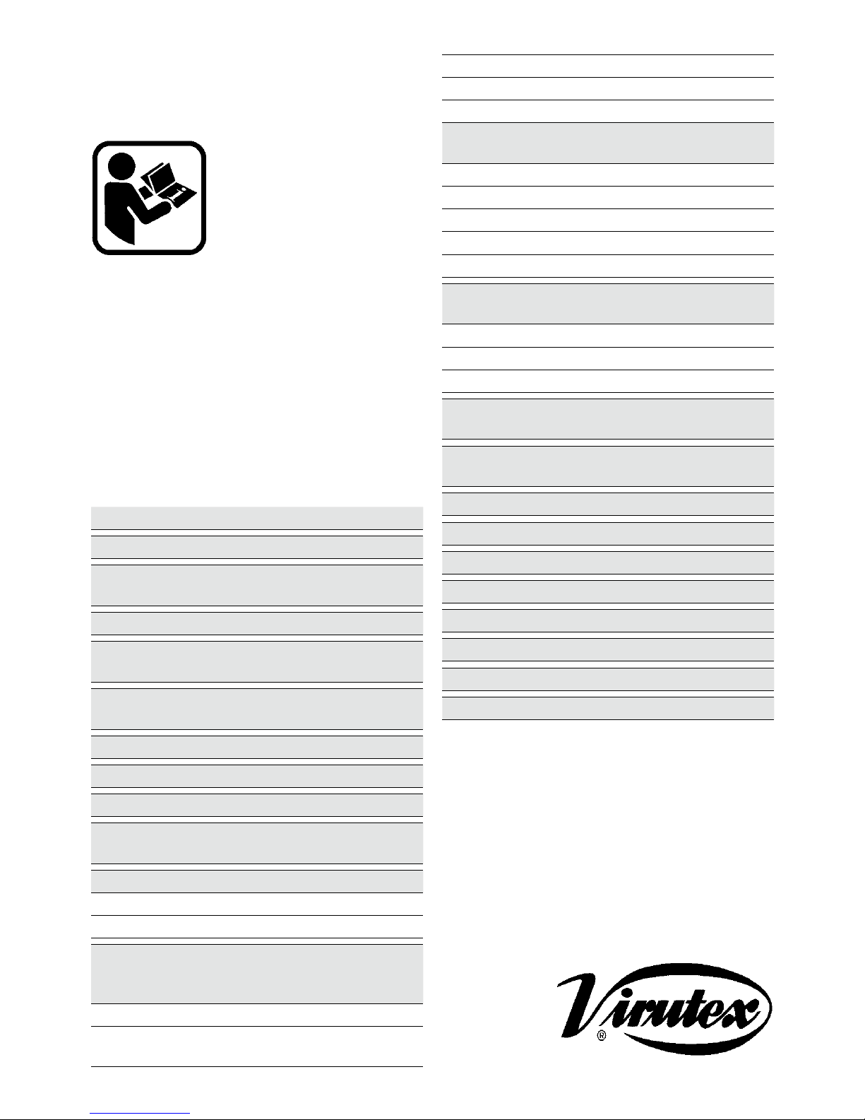
2. UTILIZACIÓN
La fresadora portátil de cajeados FC116U es una herramienta
eléctrica, destinada al fresado de mortajas para montar cerraduras de puertas, ensambles a caja, etc.
Además de la caja para la cerradura, puede fresar también el
encaje para la placa frontal de la cerradura y el encaje para la
placa del cerradero en el marco. Así mismo, con ayuda del útil
UC16I que se incluye en el equipo, puede taladrar los pasos para
el cilindro o bombín y para la manija en la puerta.
Page 4
4 - FC116U / Manual de instrucciones
3. INSTRUCCIONES DE SEGURIDAD
PARA EL MANEJO DE LA MAQUINA
Asegúrese de que la persona que va a usar esta
máquina, lea cuidadosamente y comprenda este
MANUAL DE INSTRUCCIONES, y el FOLLETO DE
INSTRUCCIONES GENERALES DE SEGURIDAD
adjunto, antes de empezar a trabajar con ella.
• Compruebe antes de conectar la máquina, que la tensión de
alimentación corresponde con la indicada en la chapa de características.
• Para cambiar la fresa o realizar cualquier otra operación cerca
del cabezal de corte, desconecte la máquina de la red eléctrica.
• Use gafas de seguridad, para trabajar con la fresadora.
• No ponga en marcha el motor, si se ha extraído del armazón
de la máquina.
• Compruebe el recorrido del cable de alimentación, para evitar
que pueda enredarse durante la utilización.
• Ponga siempre en marcha la fresadora mediante la palanca
del interruptor principal.
• Una vez situada la fresadora sobre la pieza a fresar, efectúe
siempre el desplazamiento de la herramienta, utilizando la manivela de avance del carro. No empuje nunca con las manos o
con herramientas extrañas.
• Asegúrese que el motor está completamente parado, antes de
sacar la fresadora de la mortaja realizada.
• Utilice siempre fresas del diámetro adecuado, correctamente
montadas en el eje acanalado.
• No utilice nunca fresas incorrectas, defectuosas o en mal estado. Utilice unicamente fresas y recambios originales VIRUTEX.
4. EQUIPO ESTÁNDAR
En el interior de la caja Ud., encontrará los elementos siguientes:
• Fresadora de cajeados FC116U
• Un útil de taladrar bombín y aguja UT16I
• Llaves de servicio y una plantilla de trazar
• Varilla de altura desmontable en 4 secciones y un tope puerta.
• Cuatro protectores de mordazas para trabajos delicados montados.
• Fresa de cajeados diámetro 16 mm.
• Manual de instrucciones y documentación diversa
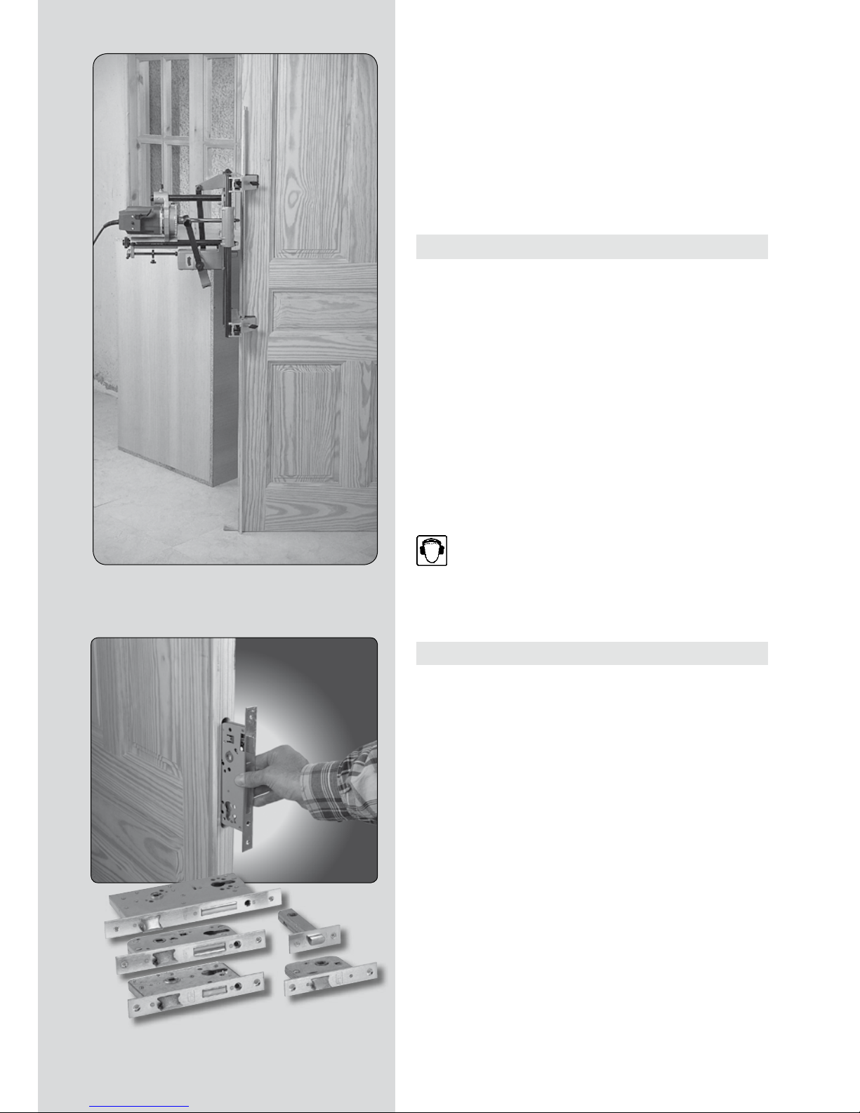
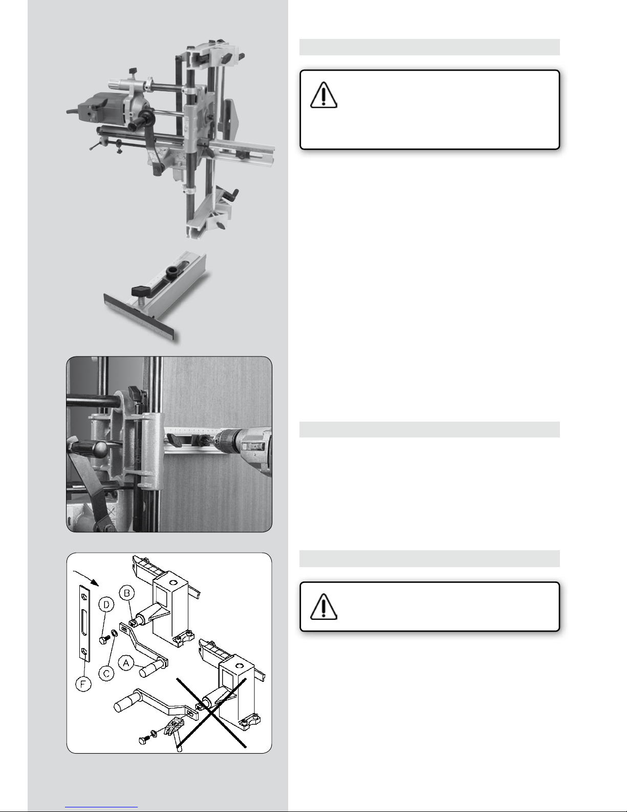
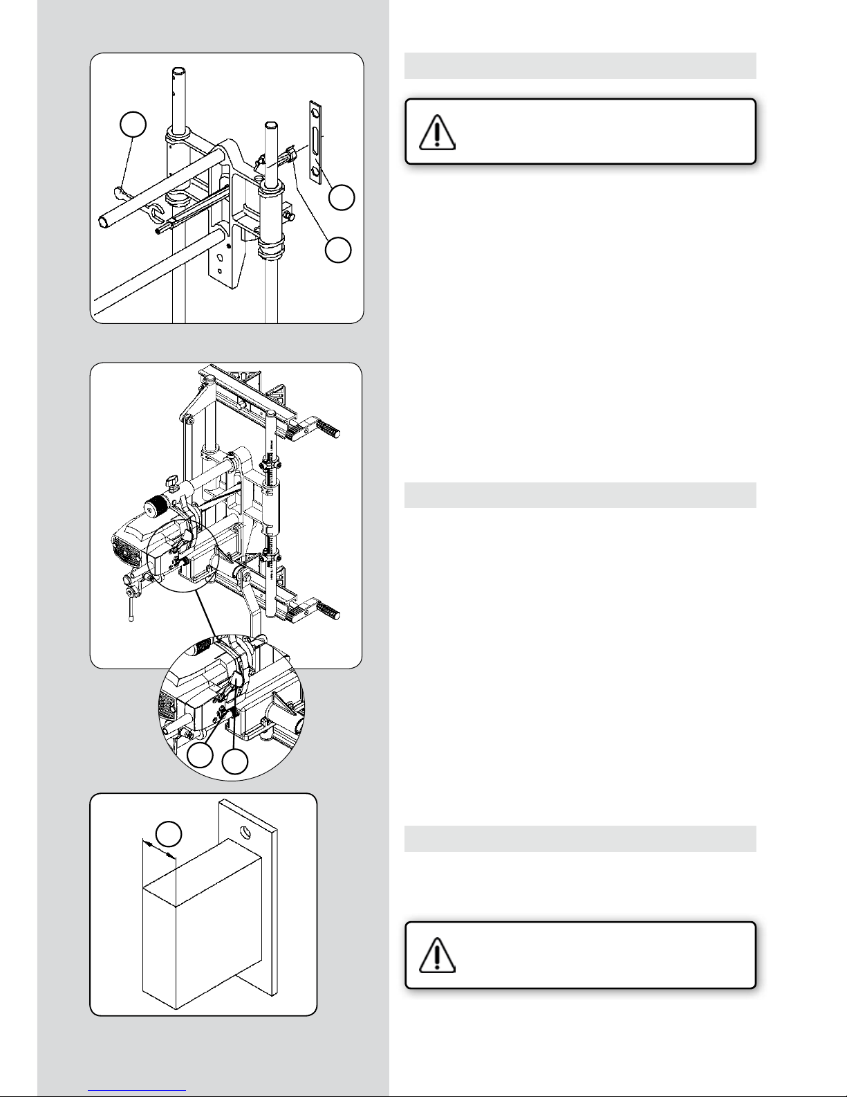
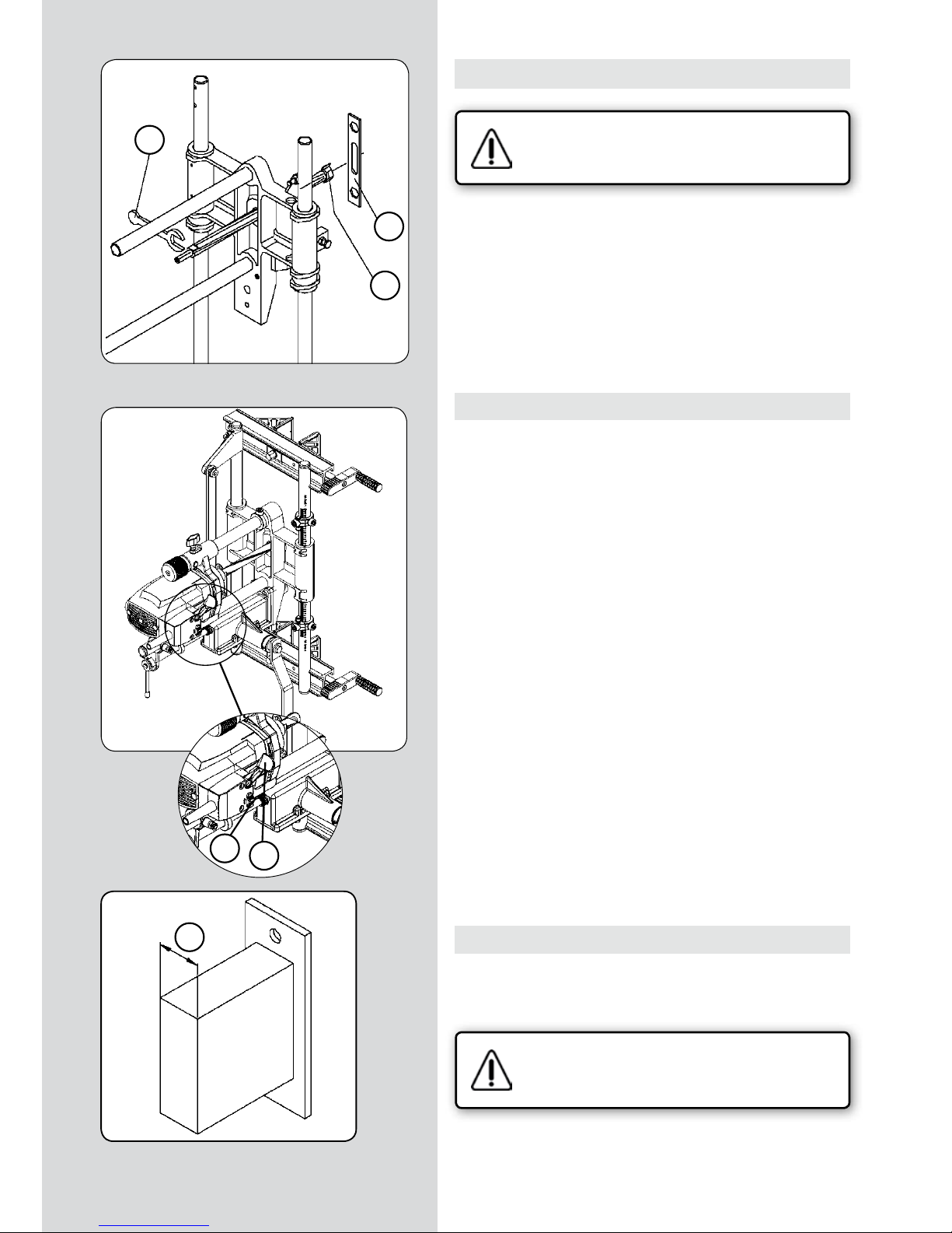
5. MONTAJE DE LA MANIVELA AVANCE CARRO
Compruebe que la fresadora se encuentra desconectada de la red eléctrica.
• Encajar la ranura rectangular de la manivela avance carro “A”,
encarándolo sobre los planos del eje “B”, poner la arandela “C”,
y el tornillo “D”, como se indica en la (Fig. 1). Apretar el tornillo
“D”, con la llave “F”, él cúal fijará la maneta avance carro, en
su alojamiento.
• ES IMPORTANTE NO GOLPEAR SOBRE LA SUPERFICIE DE LA
MANETA AVANCE “A”
Fig. 1
(Figura 1)
Page 5
FC116U / Manual de instrucciones - 5
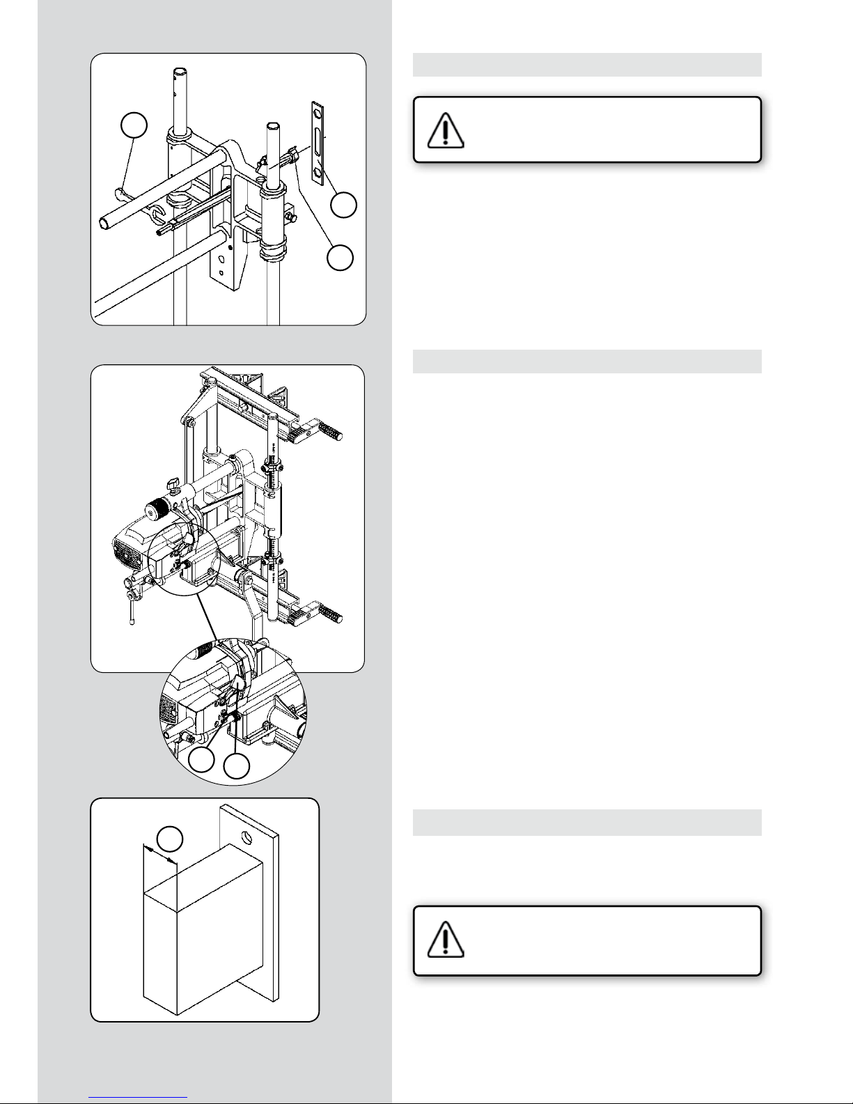
6. MONTAJE DE LAS HERRAMIENTAS DE CORTE
Compruebe que la fresadora se encuentra desconectada de la red eléctrica.
• La fresadora de cajeados se suministra, con una fresa de diámetro 16 mm montada en el extremo del eje acanalado.
Para cambiar la fresa, bloquee el eje acanalado por sus planos,
con la llave “E” (Fig. 2), desenrosque la fresa “G” con la llave “F”
y sustitúyala por otra del diámetro deseado.
7. INTERRUPTOR
• La caja del interruptor, (Fig. 3), está provista de una palanca
“Y”, para el arranque de la máquina y un seguro de enclave
lateral “Z”. Para efectuar el arranque, se acciona el seguro de
enclave “Z” y, sin soltarlo, se pulsa la palanca “Y” manteniéndose
así, la máquina en marcha.
Al pulsar la palanca “Y” con la máquina en marcha, el seguro “Z”
se desenclava automáticamente y la máquina se para.
El seguro de enclave del interruptor “Z”, impide la puesta en
marcha accidental de la máquina.
8. AJUSTE DE LA ANCHURA DEL FRESADO
• Mida el punto más ancho “N”, de la caja de la cerradura, incluyendo cualquier protuberancia que tenga, (Fig. 4). NO INCLUYA
la cara embellecedora exterior de la cerradura.
Compruebe que la fresadora se encuentra desconectada de la red eléctrica.
• Coloque una fresa de cajeados de la medida tomada o ligeramente mayor, siguiendo las instrucciones del apartado 6.
(Figura 4)
(Figura 2)
(Figura 3)
Y
E
G
F
Z
N
Page 6

6 - FC116U / Manual de instrucciones
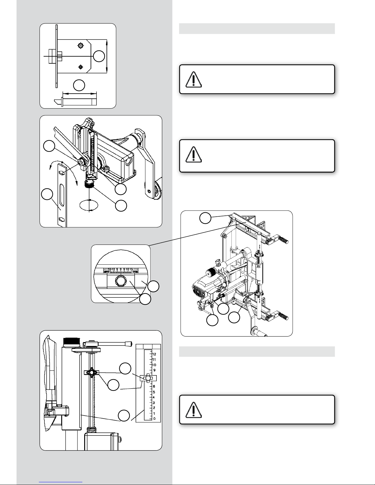
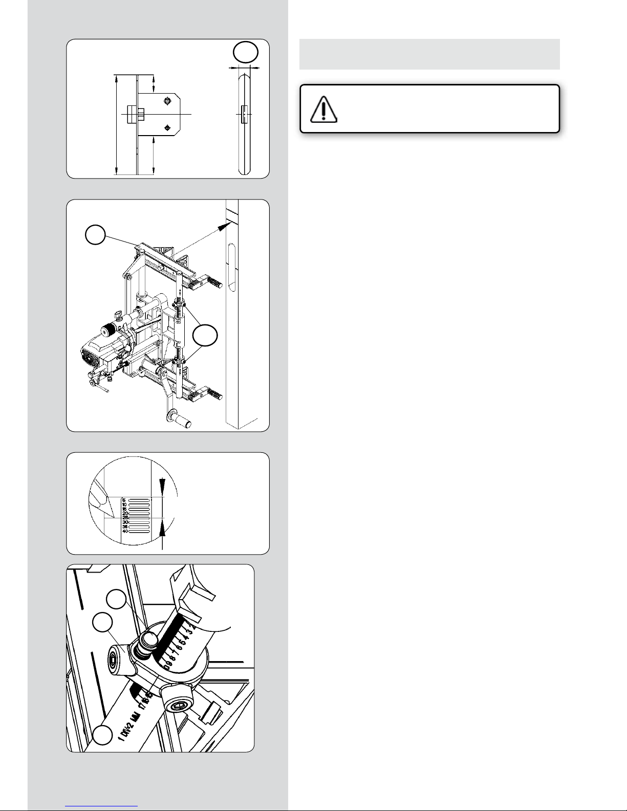
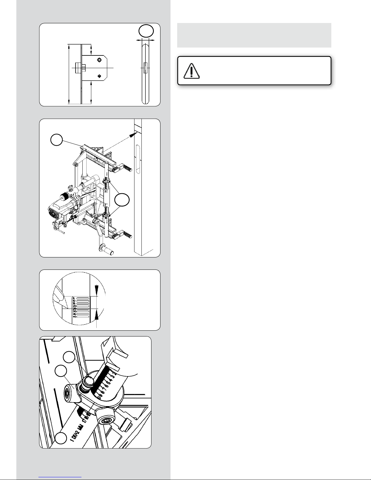
9. AJUSTE DE LA LONGITUD DEL FRESADO
• Mida el punto más largo “H”, de la caja de la cerradura, incluyendo cualquier protuberancia que tenga, (Fig. 5). NO INCLUYA
la cara embellecedora exterior de la cerradura.
Compruebe que la fresadora se encuentra desconectada de la red eléctrica.
• Para ajustar la máquina a la longitud de fresado “H” deseada,
afloje la tuerca “P” (Fig. 6) con la llave “F” y accione el pomo
husillo “R” hasta que el Indicador de longitud “S” alcance la
medida deseada “H” y apriete la tuerca “P” en esta posición.
Asegurese de apretar la tuerca “P” (Fig. 6), de lo
contrario se puede producir la rotura del mecanismo de ajuste de longitud de fresado.
El centraje de la fresa sobre el grueso de la puerta o de la pieza
a cajear, es automático, si las plaquitas “J” (Fig. 7) están en posición “0”, en las dos guías mordaza “V”, (Fig. 7).
10. AJUSTE DE LA PROFUNDIDAD DE FRESADO
• Mida la profundidad “T” (Fig. 5) de la caja de la cerradura,
incluyendo cualquier protuberancia que tenga en su fondo, el
grueso de la cara embellecedora exterior, y unos mm más como
holgura.
Compruebe que la fresadora se encuentra desconectada de la red eléctrica.
• La profundidad de fresado se controla por medio de la regla
graduada “U” (Fig. 8) la cual esta marcada en divisiones de 1
mm. Afloje el pomo “W” y sitúe el anillo “A”, de modo que su
cara inferior coincida con la profundidad deseada, y apriete el
pomo “W” en esa posición.
(Figura 6)
(Figura 8)
(Figura 5)
T
H
F
R
P
S
W
A
U
(Figura 7)
J
V
V
V
A
W
Page 7

FC116U / Manual de instrucciones - 7
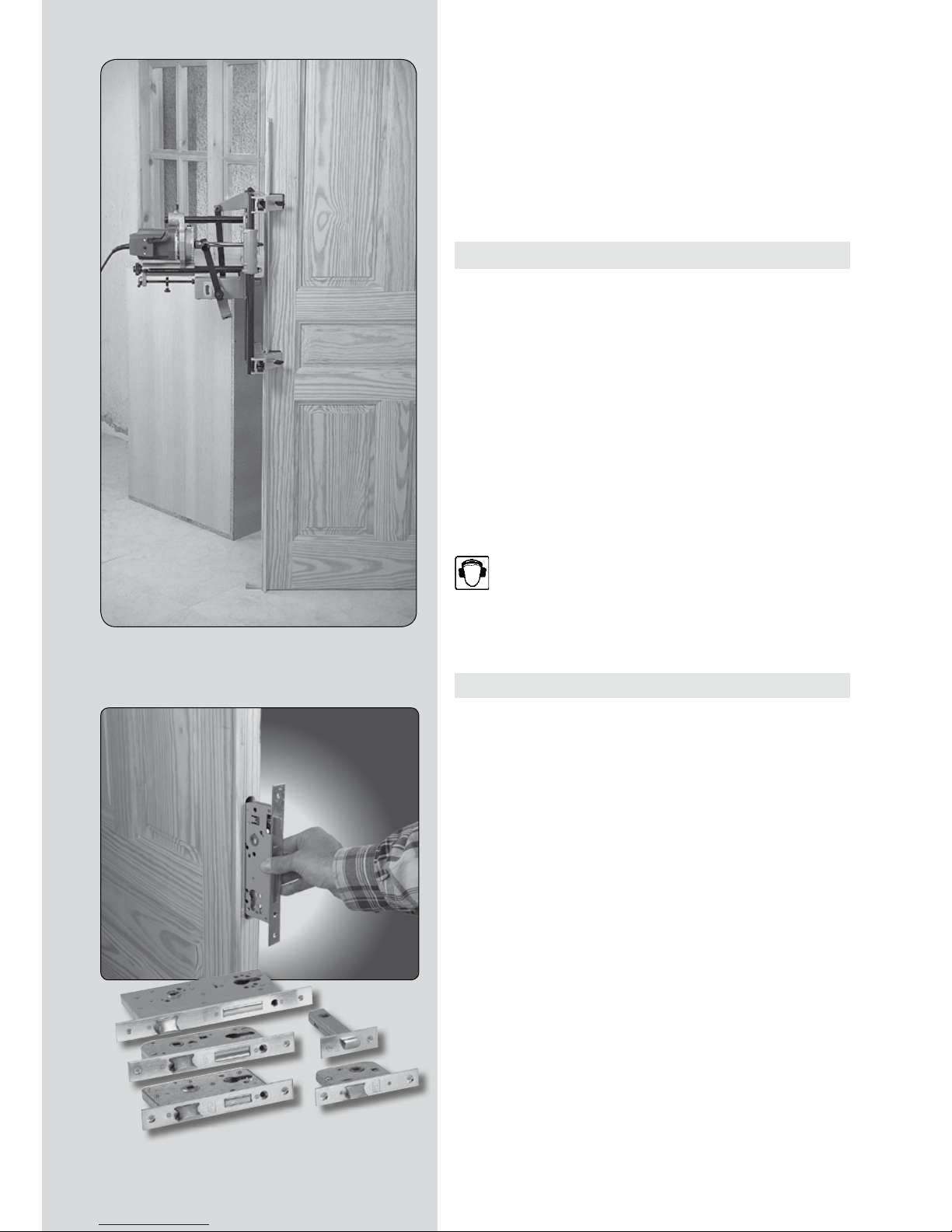
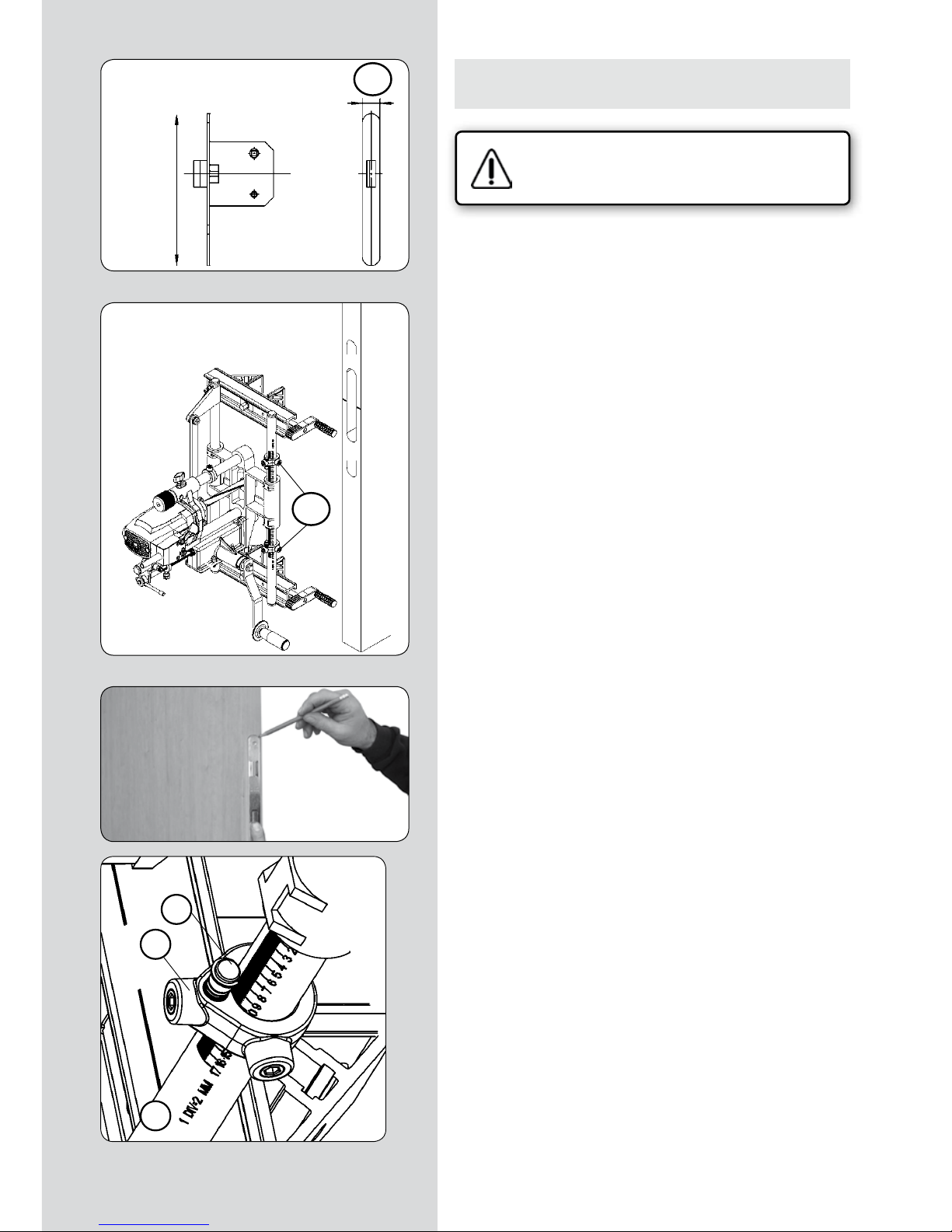
11. FRESADO DE CAJEADO EN UNA PUERTA
• Coloque la puerta en posición y fíjela firmemente para que
no se mueva. Si la puerta ya se encuentra montada en el marco,
ponga cuñas debajo de ella, para que no se mueva.
MEDIR Y TRAZAR REFERENCIAS
• Sitúe la cerradura contra la puerta, de modo que el paso para
el pomo o manija, quede a la altura deseada del suelo”H0” (Fig.
9), y marque un trazo “0” (Fig. 9) en la cara y en el canto de la
puerta.
• Mida la distancia “H2” (Fig. 9), desde el centro de la manija al
centro de la caja de la cerradura.
• Trazar el centro “c” de la caja de la cerradura, sobre el
canto de la puerta, usando para ello la plantilla de trazar
“Pt” (Fig. 9), que se libra con el equipo.
Esta plantilla dispone de una colección de ranuras situadas a 5
mm entre ellas; de modo que debe situar la plantilla sobre el
canto de la puerta, haciendo coincidir el trazo “0” (Fig. 9), con
la ranura que se corresponda con la medida “H2” (Fig. 9) que ha
tomado anteriormente, (20 mm en la Fig. 9), y marcar el trazo
“c” (Fig. 9) en el borde inferior de la plantilla.
• Trazar la referencia superior “rs” (Fig. 9), que servirá como
referencia para el montaje de la máquina sobre la puerta.
Para ello situar el extremo inferior de la plantilla de trazar “Pt”
(Fig. 9) sobre el trazo “c” (Fig. 9), y marque el trazo “rs” (Fig. 9)
en el extremo superior de la plantilla.
(Figura 9)
Pt
"c"
"H2"
"rs"
"H2"
"0"
"rs"
"rs"
"c"
"H0"
"0"
"c"
"c"
"c"
"0"
"H2"
Page 8
8 - FC116U / Manual de instrucciones
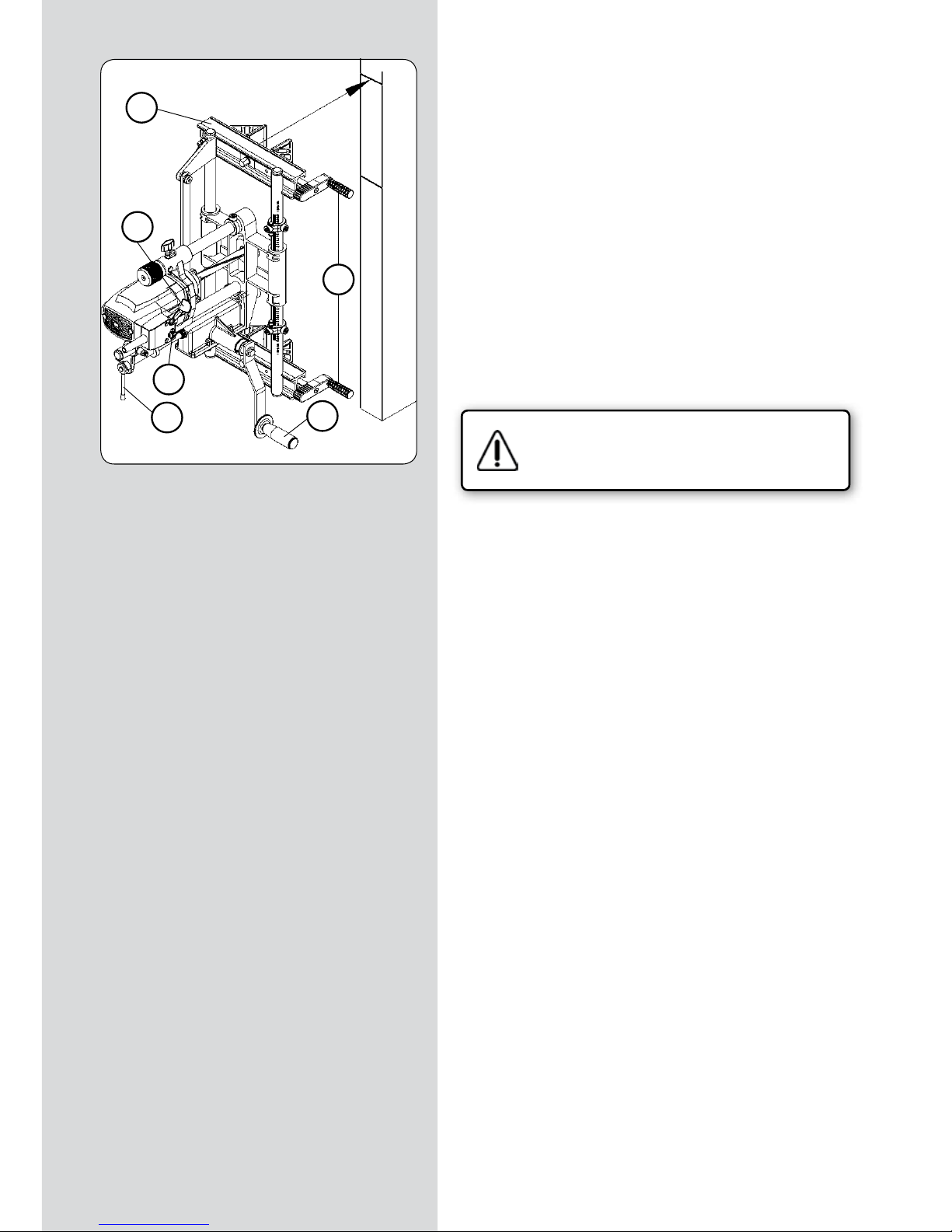
FRESAR EL ENCAJE DE LA CAJA
• Sujetar la máquina sobre la puerta, alineando la arista superior del travesaño “V” (Fig. 10), con el trazo de referencia
superior “rs” (Fig. 10) y fije firmemente las mordazas con las
manivelas “K” (Fig. 10).
• Comprobar que la manivela de avance “A” (Fig. 10), pueda
girar libremente en todo su recorrido.
• Girar la varilla blocaje “J” (Fig. 10) a la posición vertical, para
engranar el mecanismo de avance de profundidad del fresado.
• Conectar la máquina a la red eléctrica, poner en marcha el
motor, presionando la palanca “Y” (Fig. 10) y enclavando el seguro “Z” (Fig. 10).
• Girar repetidamente la manivela de avance “A” (Fig. 10), con
lo que obtendrá un avance sincronizado de la herramienta, longitudinal y en profundidad, hasta el final del recorrido fijado
en el apartado 10.
• Detener la máquina, accionando la palanca “Y” (Fig. 10).
Desconecte la fresadora de la red eléctrica.
• Girar la varilla blocaje “J” (Fig. 10) a la posición horizontal, con
lo que queda liberado el mecanismo de avance de la herramienta y el motor retrocede hasta el final de recorrido.
(Figura 10)
V
Y
K
J
Z
A
"rs"
"c"
Page 9
FC116U / Manual de instrucciones - 9
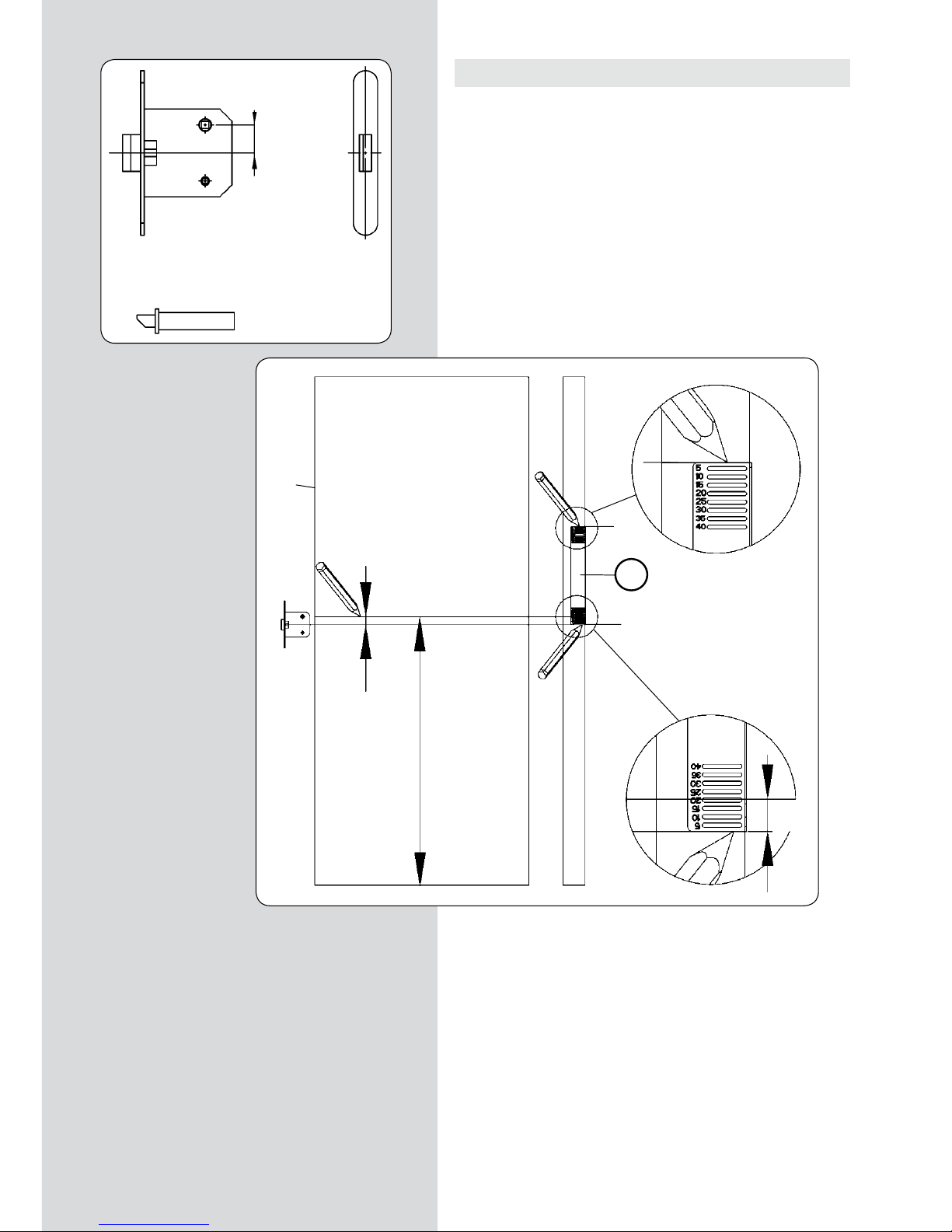
12.1. FRESADO DEL ENCAJE PARA LA PLACA FRONTAL DE
LA CERRADURA PARA "Nt" MÁXIMO DE 170 mm
Compruebe que la fresadora se encuentra desconectada de la red eléctrica.
CAMBIAR LA FRESA
• Mida el ancho “N1” (Fig. 11) del frontal de la cerradura y monte en la máquina una fresa de cajeados de la medida correspondiente, siguiendo las instrucciones del apartado 6 del manual.
MEDIR, TRAZAR REFERENCIA Y SITUAR FC116U EN LA
PUERTA
• Tome las medidas entre la caja de la cerradura y cada uno de
los dos extremo del frontal de la cerradura “N2” y “N3” (Fig. 11).
• Si las dos medidas “N2” y “N3” (Fig. 11) son iguales: Sujetar la máquina sobre la puerta, alineando la arista superior del
travesaño “V” (Fig. 12), con el trazo de referencia superior “rs”
(Fig. 12), con lo que quedan alineados los centros de la carrera
de la máquina; de la caja cerradura y de la placa frontal de la
cerradura.
• Si las medidas “N2” y “N3” (Fig. 11) no son iguales, tomar
la diferencia entre ambas “N2”-”N3”=X mm (Fig. 11); trazar
una nueva marca de referencia superior “rs1” (Fig. 13 y 12),
desplazada X mm, hacia el lado de la medida mayor entre la
“N2” y “N3” y a continuación sujetar la máquina sobre la puerta,
alineando la arista superior del travesaño “V” (Fig. 12), con el
nuevo trazo de referencia superior “rs1” (Fig. 12), con lo que
quedan alineados el centro de la carrera de la máquina, con el
centro de la placa frontal de la cerradura.
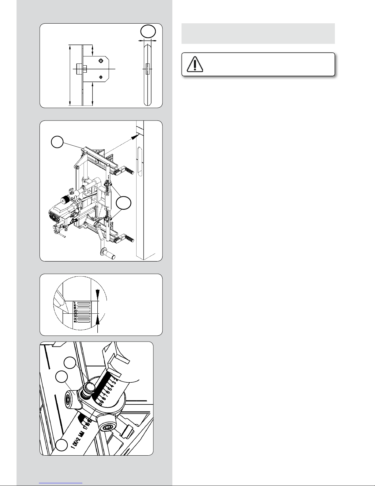
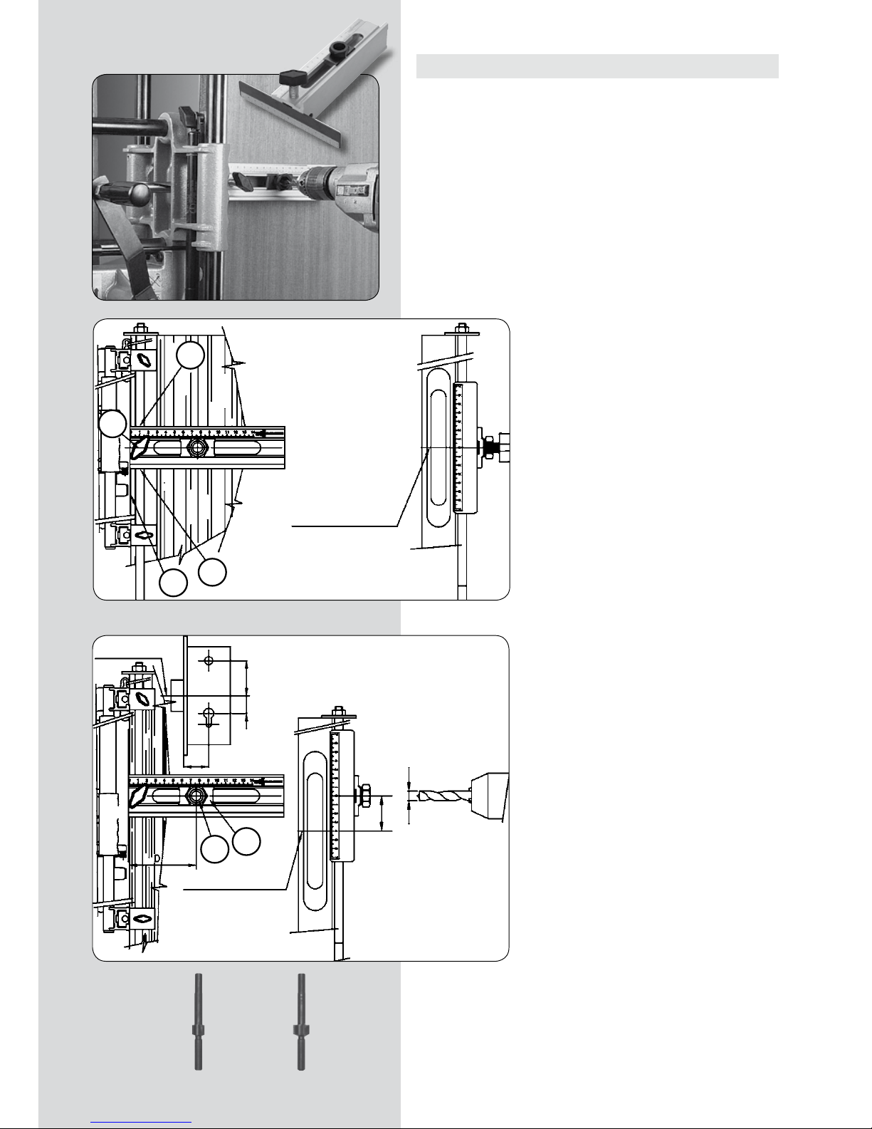
REGULAR LA CARRERA DEL FRESADO
• Medir la longitud del frontal “NT” (Fig. 11) de la cerradura
y fijar los dos topes longitudinales “S1” (Fig. 12 y 14), sobre
la división correspondiente a la medida NT, en la escala de la
columna guia “S” (Fig. 14).
• Situar y fijar los dos topes correctores del diámetro de la fresa
“S2” (Fig. 14), sobre la marca correspondiente al diámetro de la
fresa que se ha montado (Fig. 14).
• Ajustar la longitud del fresado en la biela, a una medida algo
mayor que el frontal de la cerradura “NT” (Fig. 11), del modo
que se explica en el apartado 9 (Fig. 6) de este manual.
(Figura 11)
N1
N2-N3= X mm
(Figura 12)
(Figura 13)
(Figura 14)
N2-N3= X mm
S1
V
S2
S1
S
"rs"
"rs1"
"rs"
"rs1"
"N3"
"Nt"
"N2"
Page 10

10 - FC116U / Manual de instrucciones
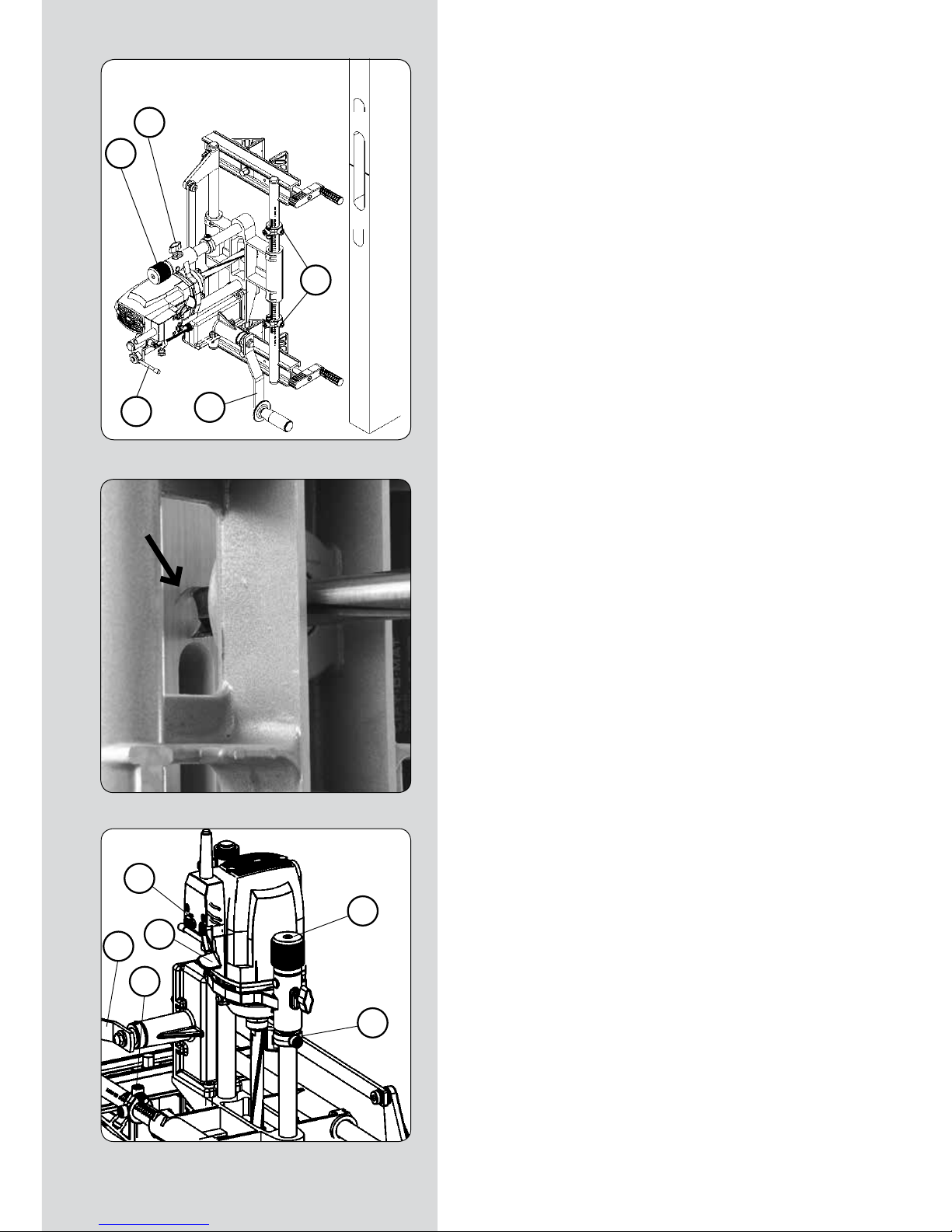
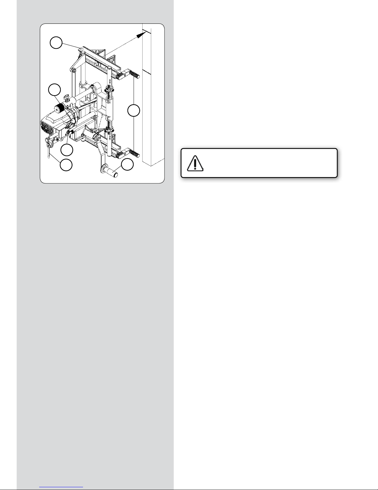
REGULAR LA PROFUNDIDAD DEL FRESADO
• Elevar el pomo “W” (Figs. 15-18) hasta su posición límite superior, girándolo en sentido anti-horario.
• Comprobar que la varilla de blocaje “J” (Fig. 15) está en posición horizontal, (avance de profundidad desconectado).
• Aflojar el pomo “K” (Fig. 16); desplazar la máquina hacia abajo, empujando suavemente con la mano sobre el motor, hasta
que la fresa toque justo el canto de la puerta y retenerla en esta
posición fijando el pomo “K” (Fig. 16).
• Colocar el frontal de la cerradura (Fig. 17), tocando la parte inferior del soporte del motor; desplazar y fijar el tope de
profundidad “S3” (Fig. 16 y 17), aprisionando el frontal de la
cerradura.
• Aflojar el pomo “K” (Figs. 15-17), para que la máquina ascienda a su posición inicial.
FRESAR EL ENCAJE
• Comprobar que la varilla de blocaje “J” (Fig. 15) está en posición horizontal, (avance de profundidad desconectado).
• Conectar la máquina a la red eléctrica, poner en marcha el
motor, presionando la palanca “Y” (Fig. 18) y enclavando el seguro de “Z” (Fig. 18).
• Girar el pomo “W” (Figs. 17 y 18) hasta que el soporte del
motor toque el tope de profundidad “S3” (Fig.18). Al alcanzar la
herramienta la profundidad de corte prevista para el frontal de
la cerradura, accionar la manivela de avance del carro “A” (Figs.
15 y 18) con suavidad, hasta alcanzar cada uno de los dos topes
“S1” (Fig. 15 y 18), situados en cada final de la carrera del carro,
en un movimiento de vaivén.
Si el encaje a realizar es mayor de 2 mm, es aconsejable efectuarlo en dos o más pasadas sucesivas, actuando repetidamente
sobre el pomo “W”.
• Restituir el pomo “W” (Fig. 18) y el tope de profundidad “S3”
(Fig. 16) a su posición inicial al terminar el fresado.
(Figura 15)
(Figura 16)
(Figura 17)
(Figura 18)
K
W
S1
A
J
rs
W
K
S3
W
K
S3
S3
W
A
Z
Y
S1
rs1
Page 11

FC116U / Manual de instrucciones - 11
12.2. FRESADO DEL ENCAJE PARA LA PLACA FRONTAL DE
LA CERRADURA PARA "Nt" MAYOR DE 170 mm
Compruebe que la fresadora se encuentra desconectada de la red eléctrica.
CAMBIAR LA FRESA
• Mida el ancho “N1” (Fig. 11.2) del frontal de la cerradura y
monte en la máquina una fresa de cajeados de la medida correspondiente, siguiendo las instrucciones del apartado 6 del
manual.
MEDIR Y TRAZAR
• Colocar la cerradura en el interior del encaje realizado para la
caja y trace los dos finales de la placa frontal sobre el canto de
la puerta. (Fig. 12.2 y 13.2)
REGULAR LA CARRERA DEL FRESADO
• Ajustar la longitud del fresado en la biela a 170 mm, del modo
que se explica en el apartado 9 (Fig. 6) de este manual.
• Fijar los dos topes longitudinales “S1” (Fig. 12.2 y 14.2), sobre
la división correspondiente a 160 mm, en la escala de la columna guia “S” (Fig. 14.2).
REGULAR LA PROFUNDIDAD DEL FRESADO
• Regular la profundidad de fresado, del modo que se explica en
el apartado 12.1 anterior.
(Figura 11.2)
N1
(Figura 12.2)
(Figura 13.2)
(Figura 14.2)
S1
S2
S1
S
"Nt"
Page 12
12 - FC116U / Manual de instrucciones
FRESAR EL ENCAJE
• Comprobar que la varilla de blocaje “J” (Fig. 15.2) está en posición horizontal, (avance de profundidad desconectado).
Fresar parte superior del encaje:
• Girar con la mano la herramienta, hasta situarla en posición
vertical (Fig. 16.2).
• Girar la manivela “A” (Fig.15.2) en sentido horario (+), hasta
alcanzar el tope superior “S1” (Fig.15.2) y asegúrese de mantenerla en esta posición.
• Soltar la máquina del canto de la puerta y desplazarla sobre el mismo verticalmente, hasta que la arista superior de la
herramienta, coincida con el trazo superior del frontal de la
cerradura (Fig.16.2) y fíje de nuevo la máquina sobre el canto
en esta posición.
• Conectar la máquina a la red eléctrica, poner en marcha el
motor, presionando la palanca “Y” (Fig. 18.2) y enclavando el
seguro de “Z” (Fig. 18.2).
• Girar el pomo “W” (Figs. 18.2) hasta que el soporte del motor
toque el tope de profundidad “S3” (Fig.18.2). Al alcanzar la herramienta la profundidad de corte prevista para el frontal de la
cerradura, accionar la manivela “A” (Figs. 15.2 y 18.2) de avance
del carro hacia abajo con suavidad, hasta alcanzar el tope “S1”
inferior (Fig. 15.2).
Si el encaje a realizar es mayor de 2 mm, es aconsejable efectuarlo en dos o más pasadas sucesivas, actuando repetidamente
sobre el pomo “W”.
Fresar la parte inferior del encaje:
• Girar con la mano la herramienta, hasta situarla en posición
vertical (Fig. 16.2).
• Girar la manivela “A” (Fig.15.2) en sentido antihorario (-),
hasta alcanzar el tope inferior “S1” (Fig.15.2) y asegúrese de
mantenerla en esta posición.
• Soltar la máquina del canto de la puerta y desplazarla sobre
el mismo verticalmente, hasta que la arista inferior de la herramienta, coincida con el trazo inferior del frontal de la cerradura
y fíje de nuevo la máquina sobre el canto en esta posición.
• Conectar la máquina a la red eléctrica, poner en marcha el
motor, presionando la palanca “Y” (Fig. 18.2) y enclavando el
seguro de “Z” (Fig. 18.2).
• Girar el pomo “W” (Figs. 18.2) hasta que el soporte del motor
toque el tope de profundidad “S3” (Fig.18.2). Al alcanzar la herramienta la profundidad de corte prevista para el frontal de la
cerradura, accionar la manivela “A” (Figs. 15.2 y 18.2) de avance
del carro hacia arriba con suavidad, hasta alcanzar el tope “S1”
superior (Fig. 15.2).
Si el encaje a realizar es mayor de 2 mm, es aconsejable efectuarlo en dos o más pasadas sucesivas, actuando repetidamente
sobre el pomo “W”.
• Restituir el pomo “W” y el tope de profundidad “S3” (Fig. 18.2)
a su posición inicial al terminar el fresado.
(Figura 15.2)
(Figura 16.2)
(Figura 18.2)
K
W
S1
A
J
S3
W
A
Z
Y
S1
Page 13

FC116U / Manual de instrucciones - 13
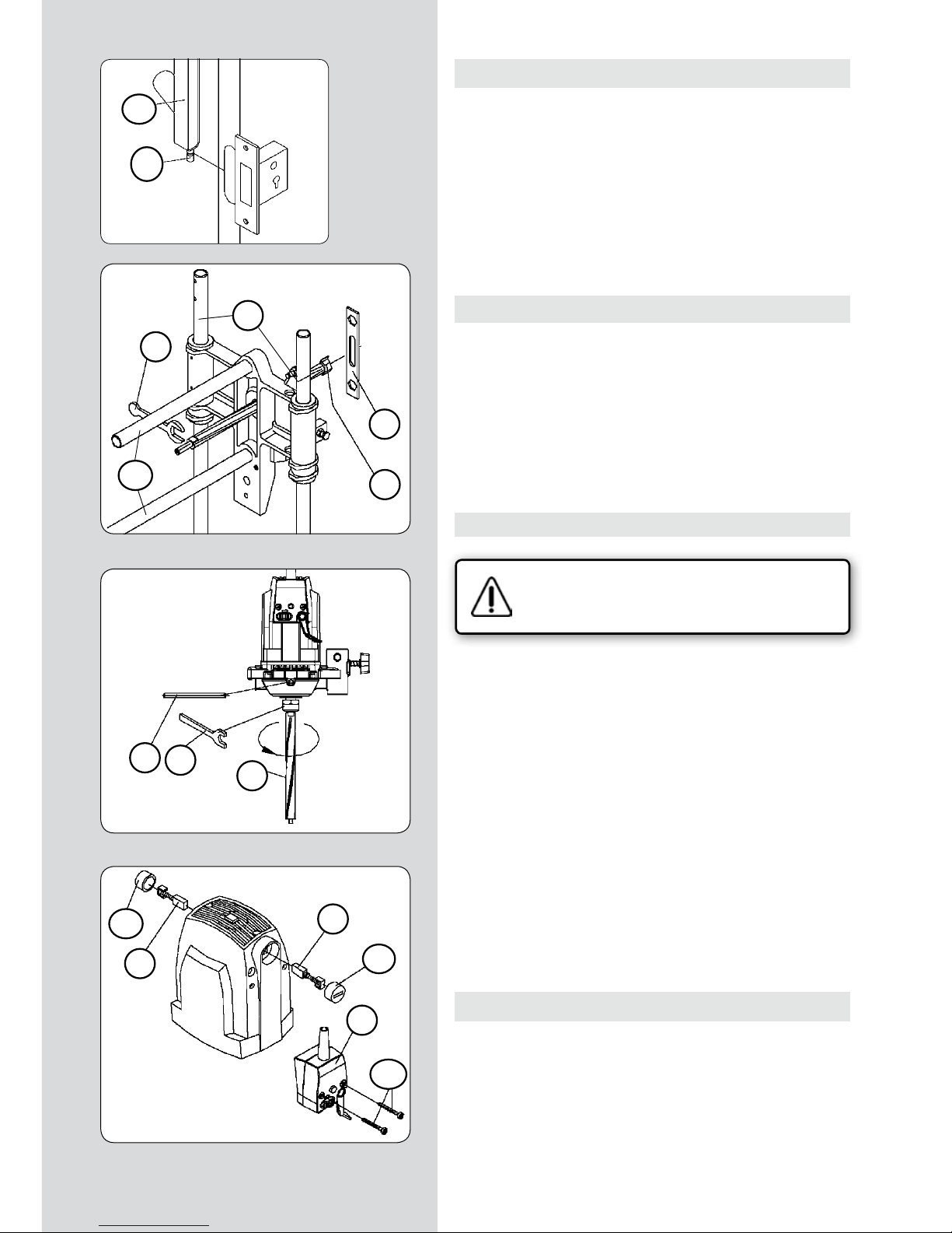
13. PERFORADO DE LOS PASOS PARA LA MANIJA Y LA
LLAVE
• Por último, con la ayuda de la plantilla UT16I suministrada
con la máquina, pueden realizarse los taladros necesarios para
el montaje de la cerradura, como los pasos de la manija, del
cierre de condena, del bombín de llave, etc.
MONTAJE DEL ÚTIL DE LA PLANTILLA
UC16I
• Introducir una varilla de altura desmontable
de las del equipo, por dentro de los agujeros
“A”, y deslizar el útil hasta situar el “0” de referencia sobre el centro “c” de la caja de la
cerradura. (Fig. 19).
• Fijar con el pomo “B” y enrasar al mismo
tiempo la cara interna “C” de la chapa de referencia en el canto de la puerta.(Fig. 19).
SITUACIÓN DEL ÚTIL Y PERFORADO
• Aflojar el casquillo guía “G”, y deslizarlo en
sentido horizontal, situando el índice “H” a la
medida “D” y apretarlo de nuevo. (Fig. 20).
• Con referencia en el centro “c” de la caja de
cerradura, deslizar el útil en sentido vertical,
para situarlo a la medida “E” y ó “F” deseada.
(Fig. 20)
• Situada la posición del agujero, se procede a
efectuar el taladro con una broca de diámetro
11 mm.
• Con referencia nuevamente al centro “c” de
la caja cerradura, se podrá situar el siguiente
agujero que necesite la cerradura.
HERRAMIENTAS OPCIONALES PARA TALADRO
1640148 Fresa de agrandar D.18 c/guía de 11
1640149 Fresa de agrandar D.23 c/guía de 11
(Figura 20)
(Figura 19)
1640148
1640149
"c"
A
A
B
"c"
centro caja cerradura "c"
C
G
H
"c"
centro caja cerradura
centro caja cerradura "c"
"c"
Page 14

14 - FC116U / Manual de instrucciones
14. FRESADO DEL CAJEADO SOBRE VARIAS PUERTAS
• Si desea cajear varias puertas y situar las cerraduras a una
misma altura, le aconsejamos emplee la varilla de alturas “A1”
(Fig. 21), que le facilitará la operación.
Para ello, después de haber determinado la altura de la cerradura en la primera puerta, y situado la máquina en posición
para fresar, monte las cuatro varillas de altura “A1” (Fig. 21), e
insértelas en los orificios de las mordazas “X” (Fig. 22), de modo
que el disco de tope “A2” (Fig. 21) de su extremo, haga tope en
el canto superior de la puerta y fije la varilla de altura “A1” (Fig.
21 y 22), en ésta posición, con los pomos “B1” (Fig. 22). Para la
próxima puerta, no tendrá mas que colocar la máquina, con el
disco de tope “A2” (Fig. 21), de la varilla de altura “A1”, descansando sobre el canto superior de la puerta y, fijar las mordazas
en esta posición, y marcar para su uso posterior, el trazo de
referencia superior “rs” en esta nueva puerta, con lo que conseguirá que todas las cerraduras queden a la misma altura.
La varilla de alturas “A1” (Fig. 21) sin el disco tope “A2” (Fig. 21),
puede emplearse también si lo desea, como referencia de altura
respecto al suelo.
15. FRESADO DE CAJEADOS EN POSICIÓN HORIZONTAL
• Para trabajar con la FC116U en posición horizontal, por ejemplo en la realización de cajeados en puertas antes de colgarlas,
es conveniente desconectar el amortiguador “T1” (Fig. 21), para
dejar libre de su presión, el movimiento del carro “U1”.
Para ello, afloje la tuerca “P” (Fig. 23) con la llave “F” y accionando el pomo husillo “R”, desplace el indicador de longitud “S”
hasta el tope “A2” de final de carrera.
Quite el pomo “S1” (Fig. 21), que sujeta el amortiguador “T1”,
para que éste quede desconectado. Guarde el pomo “S1” en lugar seguro, para una próxima utilización.
Finalmente ajuste la longitud de fresado deseada, del modo
indicado en el apartado 9, antes de trabajar con la máquina,
ya que ésta no debe trabajar nunca en el final de carrera, por
encima de la longitud máxima.
16. CORRECCIONES PARA PUERTAS SOLAPADAS
Para el cajeado de puertas con solape, deberá corregir el centraje de la máquina y la profundidad de fresado del siguiente
modo:
Compruebe que la fresadora se encuentra desconectada de la red eléctrica.
• Para centrar la máquina, sobre la sección de puerta sin solape,
afloje con la llave “F” (Fig. 22), los tornillos “Q” que bloquean las
mordazas “X” y desplace las placas “J” hacia el lado del solape, la
mitad de la anchura de éste en mm, y fije de nuevo los tornillos
“Q” en esta posición.
• Al ajustar la profundidad de fresado, como se explica en el
apartado 10, deberá situar el anillo de tope “A” (Fig. 8), a una
altura de la escala “U” (Fig. 8), que sea la suma de la profundidad necesaria para la cerradura, más la altura del solape de la
puerta, ya que la máquina se apoyará sobre este solape.
(Figura 21)
(Figura 22)
(Figura 23)
S1
A2
U1
T1
A1
A2
P
F
R
S
X
A1
B1
X
J
F
Q
Page 15

FC116U / Manual de instrucciones - 15
17. ACOPLAMIENTO DE ASPIRACIÓN
• La fresadora de cajeados FC116U, dispone de una boquilla
“D2” (Fig. 24), que montada en la varilla de posición “D1” (Fig.
24), sobre la abertura de la caja a realizar, permite la conexión
a los aspiradores Virutex AS182K, AS282K, AS382L y ASC482U,
o a otro aspirador industrial, para la extracción de la viruta del
fresado.
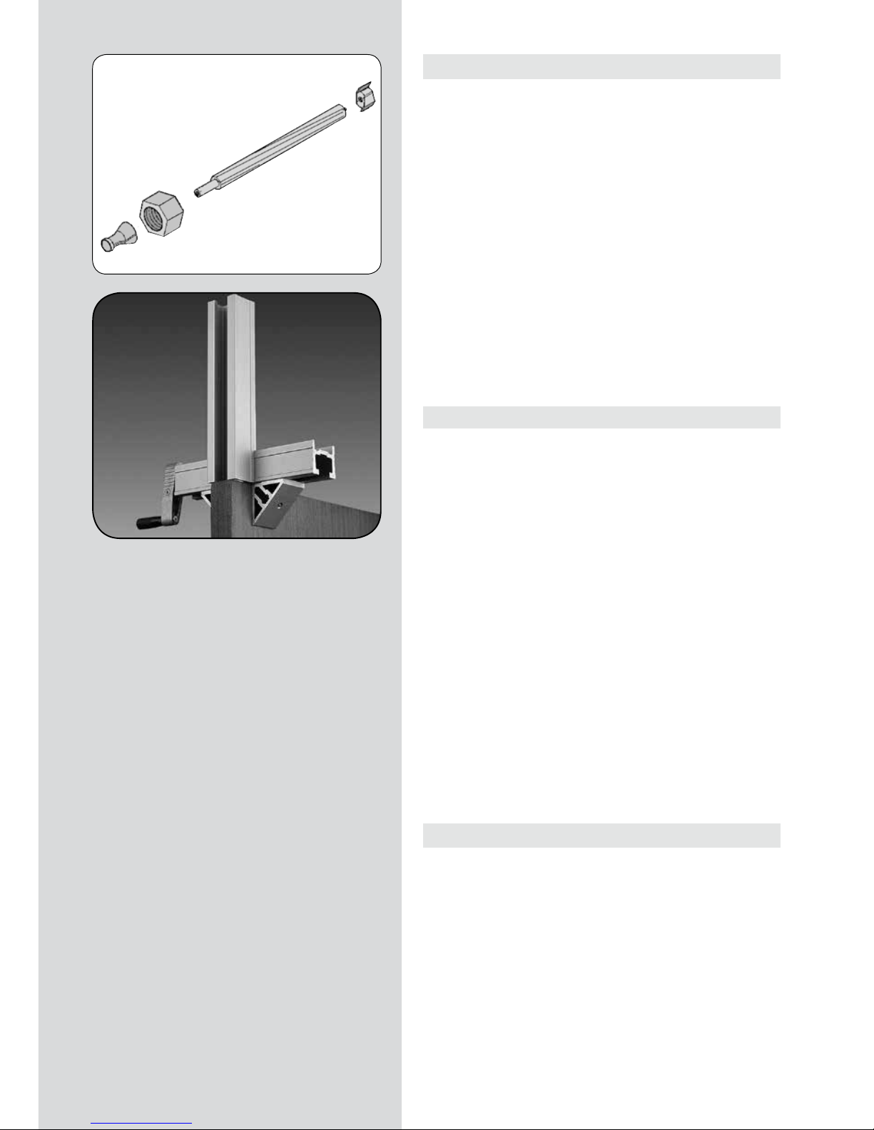
18. EXTRACCIÓN DEL EJE ACANALADO
Para cambiar el eje acanalado “M” (Fig. 26) desmonte primero la
fresa “G” (Fig. 25), como se explica en el apartado 6.
Coloque el pasador “L” (Fig. 26) en el orificio central de la carcasa, hasta bloquear el eje del motor y extraiga el eje acanalado
“M” con la llave “E”.
19. CAMBIO DE ESCOBILLAS
Asegúrese que la máquina esté desconectada
de la red eléctrica antes de realizar cualquier
manipulación.
• Las escobillas deben ser sustituidas cuando tengan una longitud mínima de 5 mm. Para ello desmonte la caja del interruptor
“F1” (Fig. 27), retirando los tornillos “G1” que la sujetan.
Quite los tapones “H1”, que sujetan las escobillas “I1” y sustitúyalas por otras originales VIRUTEX, comprobando que deslicen
suavemente en el interior de las guías. Asegúrese al montar de
nuevo la caja interruptor “F1”, de que los cables queden bien
situados en su interior.
Es aconsejable dejar la máquina en marcha en vacío durante
algunos minutos después de un cambio de escobillas. Aproveche
el cambio de escobillas para verificar el estado del colector. Si
éste presentase quemaduras o resaltes, es aconsejable llevarlo a
reparar, a un Servicio Técnico VIRUTEX.
20. LUBRICACIÓN Y LIMPIEZA
• Antes de fresar el primer encaje, lubrique las columnas de guía
de la profundidad “Gp” (Fig. 25) y las transversales “Gt” (Fig. 25),
con un trapo ligeramente impregnado en aceite, para suavizar
los dos movimientos. Es importante limpiar siempre la máquina
después de su utilización, con un chorro de aire seco.
Mantenga siempre el cable de alimentación en perfectas condiciones de uso.
(Figura 25)
(Figura 24)
(Figura 26)
(Figura 27)
E
D2
D1
F
G
L
E
M
Gt
Gp
F1
G1
H1
I1
I1
H1
Page 16
16 - FC116U / Manual de instrucciones
21. HERRAMIENTAS Y ACCESORIOS OPCIONALES
• Fresas para fresadora de cajeados FC116U disponibles:
NÚMERO DIAM.EXT. ALTURA
1640127 16 mm. 13.5 mm.
1640150 17 “ 13.5 “
1640128 18 “ 13.5 “
1640367 20 “ 13.5 “
1640129 21 “ 13.5 “
1640130 23 “ 13.5 “
1640368 23,5 “ 13.5 “
1640131 25 “ 13.5 “
1640369 29 “ 13.5 “
1640132 30 “ 13.5 “
1640140 Fresa de taladrar Ø 24
• El útil prolongador UP16I, 1645287, permite prolongar la sujección de la máquina más allá de la propia puerta.
22. NIVEL DE RUIDO Y VIBRACIONES
Los niveles de ruido y vibraciones de esta herramienta eléctrica
han sido medidos de acuerdo con la Norma Europea EN 610291 y sirven como base de comparación con máquinas de semejante aplicación.
El nivel de vibraciones indicado ha sido determinado para las
aplicaciones principales de la herramienta, y puede ser utilizado
como valor de partida para la evaluación de la exposición al
riesgo de las vibraciones. Sin embargo, el nivel de vibraciones
puede llegar a ser muy diferente al valor declarado en otras
condiciones de aplicación, con otros útiles de trabajo o con un
mantenimiento insuficiente de la herramienta eléctrica y sus
útiles, pudiendo llegar a resultar un valor mucho más elevado
debido a su ciclo de trabajo y modo de uso de la herramienta
eléctrica.
Por tanto, es necesario fijar medidas de seguridad de protección
al usuario contra el efecto de las vibraciones, como pueden ser
mantener la herramienta y útiles de trabajo en perfecto estado
y la organización de los tiempos de los ciclos de trabajo (tales como tiempos de marcha con la herramienta bajo carga, y
tiempos de marcha de la herramienta en vacío y sin ser utilizada
realmente ya que la reducción de estos últimos puede disminuir
de forma sustancial el valor total de exposición).
23. GARANTÍA
Todas las máquinas electroportátiles VIRUTEX, tienen una garantía válida de 12 meses a partir del día de su suministro, quedando excluidas todas las manipulaciones o daños ocasionados
por manejos inadecuados o por desgaste natural de la máquina.
Para cualquier reparación dirigirse al Servicio Oficial de Asistencia VIRUTEX S.A.
VIRUTEX, se reserva el derecho de modificar sus productos sin
previo aviso.
Page 17
FC116U / Operating instructions - 17
INDEX
Specifications are subject
to change without prior
notice.
OPERATING INSTRUCTIONS
1 TECHNICAL INFORMATION 18
2 USE 18
3 MACHINE HANDLING
SAFETY INSTRUCTIONS 19
4 STANDARD UNIT 19
5 ASSEMBLING THE
CARRIAGE ADVANCE HANDLE 19
6 MOUNTING THE CUTTING TOOL 20
7 SWITCH 20
8 ADJUSTING THE TRIMMING WIDTH 20
9 ADJUSTING THE TRIMMING LENGTH 21
10 ADJUSTING THE TRIMMING DEPTH 21
11
MORTISING EDGE TRIMMING ON A DOOR
22
MEASURING AND TRACING REFRENCES 22
TRIMMING THE BOX FITTING 23
12.1
TRIMMING THE FITTING FOR THE FRONT PLATE
OF THE LOCK FOR A MAXIMUM "Nt" OF 170 mm
24
CHANGING THE TRIMMING 24
MEASURING, MARKING REFERENCE POINTS
AND PLACING THE FC116U ON THE DOOR
24
ADJUST THE TRIMMING PATH 24
ADJUSTING THE DEPTH OF THE TRIM 25
TRIMMING THE FITTING 25
12.2
TRIMMING THE FITTING FOR THE FRONT
PLATE OF THE LOCK FOR AN "Nt" OF MORE
THAN 170 mm
26
CHANGING THE TRIMMING 26
MEASURING AND MARKING 26
ADJUST THE TRIMMING PATH 26
ADJUSTING THE DEPTH OF THE TRIM 26
TRIMMING THE FITTING 27
13 DRILLING THE HOLES FOR
THE HANDLE AND KEY 28
ASSEMBLING THE TOOL FOR THE UC16I
TEMPLATE 28
POSITIONING THE TOOL AND PERFORATING
28
OPTIONAL DRILLING TOOLS 28
14 TRIMMING THE LOCKS FOR SEVERAL
DOORS 29
15 HORIZONTAL MORTISING 29
16
CORRECTIONS FOR OVERLAPPING DOORS
29
17 DUST COLLECTOR ATTATCHMENT 30
18 REMOVING THE SPLINE SHAFT 30
19 CHANGING THE BRUSHES 30
20 LUBRICATION AND CLEANING 30
21 OPTIONAL TOOLS AND ACCESSORIES 31
22 NOISE AND VIBRATION LEVEL 31
23 WARRANTY 31
Page 18
18 - FC116U / Operating instructions
FC116U LOCK MORTISER
IMPORTANT
Read these OPERATING INSTRUCTIONS and the attached GENERAL SAFETY INSTRUCTIONS LEAFLET carefully before using the
machine. Make sure you have understood them before operating
the machine for the first time. Keep both sets of instructions for
any future queries.
1. TECHNICAL INFORMATION
Universal motor.............................................................................50/60 Hz
Power................................................................................................1,100 W
No-load speed..........................................................................23,000 min
-1
Maximum bit diameter....................................................................30 mm
Maximum trimming depth......................................................0-125 mm
Maximum trimming width...................................................bit diameter
Maximum trimming length.................................177 mm + bit diameter
Maximum opening of the clamp vises........................................190 mm
Maximum grip of the clamp vises....................................................13 mm
Side movement of the bit over thickness of door...........+/- 15 mm
Weight...................................................................................................14 Kg
Weighted equivalent continuous acoustic pressure level A......87 dBA
Acoustic power level A.........................................................................98 dBA
Uncertainty......................................................................................K = 3 dbA
Wear ear protection!
Vibration total values............................................................a
h
: <2.5 m/s
2
Uncertainty................................................................................K: 1.5 m/s
2
2. USE
The FC116U portable lock mortiser is an electrical tool, for the
trimming of mortises to mount door locks, mortise assemblies,
etc.
In addition to the box for the lock, you can also trim the fitting
for the front plate of the lock. With the help of the tool UC16I,
which comes with the equipment, you can drill the entry points
in the door for the cylinder and the handle.
Page 19
FC116U / Operating instructions - 19
3. MACHINE HANDLING SAFETY INSTRUCTIONS
Ensure that the person who is to use this machine reads these OPERATING INSTRUCTIONS and
the enclosed GENERAL SAFETY INSTRUCTIONS
LEAFLET carefully and understands them before
starting work.
• Before connecting the machine, ensure that the power supply
voltage corresponds to that indicated on the characteristics plate.
• To change the bit or carry out any other operation close to the
cutting head, disconnect the machine from the mains.
• Use safety goggles when working with the trimmer.
• Do not start the motor if the machine chassis has been removed.
• Check the power supply cable to make sure it does not twist
during use.
• Always start the trimmer using the main switch lever.
• Once the trimmer has been placed on the part to be trimmed,
always move the tool using the carriage advance crank handle.
Never push it by hand or with extraneous tools.
• Ensure that the motor is at a complete standstill before removing the trimmer from the completed mortise.
• Always use bits of the correct diameter, correctly mounted on
the serrated axis.
• Never use bits that are incorrect, defective or in bad condition.
Use only authentic VIRUTEX bits and spare parts.
4. STANDARD UNIT
The following elements are included in the box:
• Lock mortiser FC116U
• Drilling tool for cylinder and needle UT16I
• Service keys and tracing template
• Detachable height bar in 4 sections and a door limiter.
• Four clamp vise protectors for precise mounted jobs.
• Mortising trimmer bit, 16 mm diameter.
• Operating Instructions and miscellaneous documen-tation.
5. ASSEMBLING THE CARRIAGE ADVANCE HANDLE
Check that the trimmer is disconnected from the
mains.
• Match the rectangular carriage forward handle slot “A” to the
planes of the shaft “B”. Fit washer “C” and screw “D”, as shown in
(Fig. 1). Tighten screw “D” with spanner “F”, to hold the carriage
advance handle in place.
• MAKE SURE NOT TO KNOCK THE SURFACE OF ADVANCE HANDLE “A”.
Fig. 1
(Figure 1)
Page 20
20 - FC116U / Operating instructions
6. MOUNTING THE CUTTING TOOL
Check that the trimmer is disconnected from the
mains.
• The mortising trimmer is supplied with a 16 mm diameter bit
mounted on the end of the spline shaft.
To change the bit, lock the spline shaft by its planes with key “E”
(Fig. 2), unscrew the bit “G” with key “F” and replace with one of
the required diameter.
7. SWITCH
• Cut-out box (Fig. 3) is equipped with lever “Y” for starting up
the machine and lateral fixing stop “Z”. To start it up, activate
fixing stop “Z” and, without releasing it, push forward lever “Y”,
thus keeping the machine running.
When lever “Y” is pushed forward with the machine running,
stop “Z” loosens automatically and the machine comes to a halt.
The switch’s fixing stop “Z” prevents the machine from starting
up accidentally.
8. ADJUSTING THE TRIMMING WIDTH
• Measure the widest point, “N”, of the lock box, including any
protuberance it may have (Fig. 4). DO NOT INCLUDE the exterior
decorative face of the lock.
Check that the trimmer is disconnected from the
mains.
• Place a mortising trimmer bit of the measurement taken or
slightly larger, according to the instructions in section 6.
(Figure 4)
(Figure 2)
(Figure 3)
Y
E
Z
N
G
F
Page 21
FC116U / Operating instructions - 21
9. ADJUSTING THE TRIMMING LENGTH
• Measure the longest point, “H”, of the lock box, including any
protuberance it may have (Fig. 5). DO NOT INCLUDE the exterior
decorative face of the lock.
Check that the trimmer is disconnected from the
mains.
• To adjust the machine to the required trimming length “H”,
loosen nut “P” (Fig. 6) with key “F” and move screw knob “R” until
the length indicator “S” reaches the desired measurement “H”,
then tighten nut “P” in this position.
Be sure to tighten nut "P" (Fig. 6); if not, this
may cause the trimming length adjustment mechanism to break.
The centring of the bit over the thickness of the door or the part
to be mortised is automatic if the small plates “J” (Fig. 7) are in
the “0” position on the two clamp vise guides “V” (Fig. 7).
10. ADJUSTING THE TRIMMING DEPTH
• Measure the depth “T” (Fig. 5) of the lock box including any
protuberance it may have at the bottom, the thickness of the
exterior decorative face and an additional few centimetres as
allowance.
Check that the trimmer is disconnected from the
mains.
• The trimming depth is controlled by the graduated rule “U”
(Fig. 8), marked in 1 mm divisions. Loosen knob “W” and position ring “A” so that the inside face coincides with the required
depth, then tighten knob “W” in this position.
(Figure 6)
(Figure 8)
(Figure 5)
T
H
F
R
P
S
W
A
U
(Figure 7)
J
V
V
V
A
W
Page 22
22 - FC116U / Operating instructions
11. MORTISING EDGE TRIMMING ON A DOOR
• Place the door vertically and fasten well so that it does not
move. If the door is already mounted on the frame, place wedges
under it to prevent it from moving.
MEASURING AND TRACING REFRENCES
• Place the lock against the door so that the path for the door
knob or handle is at the desired height from the ground “H0”
(Fig. 9) and mark the point “0” (Fig. 9) on the face and edge of
the door.
• Measure the distance “H2” (Fig. 9) from the centre of the
handle to the centre of the box for the lock.
• Mark the centre “c” of the box for the lock onto the edge
of the door using the tracing template “Pt” (Fig. 9), which
comes with the equipment.
This template has a set of grooves 5 mm apart. You must place
the template onto the edge of the door so that the mark “0” (Fig.
9) is lined up with the groove that corresponds to the measurement “H2” (Fig. 9) made earlier (20 mm in Fig. 9). Now make the
“c” mark (Fig. 9) on the lower edge of the template.
• Trace the upper reference “rs” (Fig. 9) which acts as a
reference for attaching the machine to the door.
To do this, place the lower edge of the tracing template “Pt” (Fig.
9) on the mark “c” (Fig. 9) and mark the point “rs” (Fig. 9) on the
upper edge of the template.
(Figure 9)
Pt
"c"
"H2"
"rs"
"H2"
"0"
"rs"
"rs"
"c"
"H0"
"0"
"c"
"c"
"c"
"0"
"H2"
Page 23
FC116U / Operating instructions - 23
TRIMMING THE BOX FITTING
• Hold the machine against the door, aligning the upper edge
of the crossbeam “V” (Fig. 10) with the upper reference tracing
“rs” (Fig. 10) and firmly fix the clamps with crank handles “K”
(Fig. 10).
• Check that the advance crank handle “A” (Fig. 7) is able to turn
freely over the whole path.
• Turn locking bar “J” (Fig. 10) to the vertical position to gear the
trimming depth advance mechanism.
• Connect the machine to the mains, switch on the motor, pressing the lever “Y” (Fig. 10) and set the safety “Z” (Fig. 10).
• Turn the advance crank handle “A” (Fig. 10) repeatedly to
effect a synchronised tool advance, both lengthways and in
depth, to the end of the path as fixed in section 10.
• Stop the machine by activating lever “Y” (Fig. 10).
Disconnect the trimmer from the mains.
• Turn the locking bar “J” (Fig. 10) to the horizontal position,
completely freeing the advance mechanism of the tool and the
motor goes back to the end of the stretch.
(Figure 10)
V
Y
K
J
Z
A
"rs"
"c"
Page 24
24 - FC116U / Operating instructions
12.1. TRIMMING THE FITTING FOR THE FRONT PLATE OF
THE LOCK FOR A MAXIMUM "Nt" OF 170 mm
Check that the trimmer is disconnected from the
mains.
CHANGING THE TRIMMING
• Measure the width “N1” (Fig. 11) of the front of the lock and
attach a mortising bit of the correct size to the machine, following the instructions in section 6 of the manual.
MEASURING, MARKING REFERENCE POINTS AND PLACING
THE FC116U ON THE DOOR
• Measure the distance between the box for the lock and each of
the two edges of the front of the lock, giving you measurements
“N2” and “N3” (Fig. 11).
• If the two measurements “N2” and “N3” (Fig. 11) are the same:
Hold the machine against the door, aligning the upper edge of
crossbeam “V” (Fig. 12) with the upper reference mark “rs” (Fig.
12), which aligns the centres of the machine’s trimming path for
the lock box and the front plate for the lock.
• If the measurements “N2” and “N3” (Fig. 11) are not the same,
calculate the difference between them, “N2”-“N3”=X mm (Fig.
11) and make a new upper reference mark “rs1” (Figs. 13 and
12), which is X mm in the direction of the side with the greater
measurement, either “N2” or “N3”. Then hold the machine against the door, aligning the upper edge of crossbeam “V” (Fig. 12),
using the new upper reference mark “rs1” (Fig. 12), which results
in the alignment of the machine’s trimming path with the centre
of the front plate for the lock.
ADJUST THE TRIMMING PATH
• Measure the length of the front “NT” (Fig. 11) of the lock and
fix the two longitudinal stops “S1” (Figs. 12 and 14) onto the
corresponding division of the measurement NT, using the scale
on the guide column “S” (Fig. 14).
• Position and fix the two correcting stops for the diameter of
the cutter bit “S2” (Fig. 14) onto the frame corresponding to the
diameter of the cutter bit attached (Fig. 14).
• Adjust the length of the trim on the connecting rod to a measurement somewhat greater than the front of the lock “NT” (Fig.
11), as explained in section 9 (Fig. 6) of this manual.
N1
N2-N3= X mm
N2-N3= X mm
S1
V
"rs"
"rs1"
"rs"
"rs1"
"N3"
"Nt"
"N2"
(Figure 11)
(Figure 12)
(Figure 13)
(Figure 14)
S2
S1
S
Page 25

FC116U / Operating instructions - 25
ADJUSTING THE DEPTH OF THE TRIM
• Raise the knob “W” (Figs. 15-18) to its maximum upper position, turning it counter-clockwise.
• Check that the lock lever “J” (Fig. 15) is in the horizontal position (advance depth disconnected).
• Loosen knob “K” (Fig. 16). Move the machine downwards,
gently pushing the motor with your hand until the bit just touches the edge of the door. Hold it in this position, tightening
knob “K” (Fig. 16).
• Place the front of the lock (Fig. 17) so that it is touching the
lower part of the motor support; move and fix the depth stop
“S3” (Figs. 16 and 17), trapping the front of the lock.
• Loosen knob “K” (Figs. 15-17) so that the machine rises to its
original position.
TRIMMING THE FITTING
• Check that the lock lever “J” (Fig. 15) is in the horizontal position (advance depth disconnected).
• Connect the machine to the mains, switch on the motor, pressing the lever “Y” (Fig. 18) and set the safety “Z” (Fig. 18).
• Turn the knob “W” (Figs. 17 and 18) until the motor support
touches depth stop “S3” (Fig. 18). When the tool reaches the
depth of cut planned for the front of the lock, move the carriage
advance crank handle “A” (Figs. 15 and 18) gently until it reaches
each of the two stops “S1” (Figs. 15 and 18) located at each end
of the carriage path, in a rocking movement.
If the fitting to be created is greater than 2 mm, it is advisable to
complete this process using two or three successive movements,
repeatedly using knob “W”.
• Return the knob “W” (Fig. 18) and the depth stop “S3” (Fig. 16)
to their initial position once the trim has been completed.
(Figure 15)
(Figure 16)
(Figure 17)
(Figure 18)
K
W
S1
A
J
rs
W
K
S3
W
K
S3
S3
W
A
Z
Y
S1
rs1
Page 26
26 - FC116U / Operating instructions
12.2. TRIMMING THE FITTING FOR THE FRONT PLATE OF
THE LOCK FOR AN "Nt" OF MORE THAN 170 mm
Check that the trimmer is disconnected from the
mains.
CHANGING THE TRIMMING
• • Measure the width “N1” (Fig. 11.2) of the front of the lock
and attach a mortising bit of the correct size to the machine,
following the instructions in section 6 of the manual.
MEASURING AND MARKING
• Position the lock inside the fitting made for the box and mark
the two ends of the front plate on the edge of the door (Fig.
12.2 and 13.2)
ADJUST THE TRIMMING PATH
• Adjust the length of the trim on the connecting rod to 170
mm, as explained in section 9 (Fig. 6) of this manual.
• Fix the two longitudinal stops “S1” (Fig. 12.2 and 14.2) on the
division corresponding to 160 mm using the scale on the guide
column “S” (Fig. 14.2).
ADJUSTING THE DEPTH OF THE TRIM
• Adjust the depth of the trim as explained in section 12.1 above.
N1
S1
"Nt"
(Figure 11.2)
(Figure 12.2)
(Figure 13.2)
(Figure 14.2)
S2
S1
S
Page 27

FC116U / Operating instructions - 27
TRIMMING THE FITTING
• Check that the lock lever “J” (Fig. 15.2) is in the horizontal
position (advance depth disconnected).
Trimming the top of the fitting:
• Manually turn the tool until it is in a vertical position (Fig.
16.2).
• Turn the handle “A” (Fig. 15.2) clockwise (+) as far as the top
stop “S1” (Fig. 15.2) and make sure it is kept in this position.
• Release the machine from the door edge and move it over the
edge vertically until the top edge of the tool coincides with the
top mark on the front of the lock (Fig. 16.2) and once again fix
the machine on the edge in this position.
• Connect the machine to the mains, switch on the motor, pressing the lever “Y” (Fig. 18.2) and set the safety “Z” (Fig. 18.2).
• Turn the knob “W” (Fig. 18.2) until the motor support touches
depth stop “S3” (Fig. 18.2). When the tool reaches the depth of
cut planned for the front of the lock, move the carriage advance
handle “A” (Figs. 15.2 and 18.2) gently as far as lower stop “S1”
(Fig. 15.2).
If the fitting to be created is greater than 2 mm, it is advisable to
complete this process using two or three successive movements,
repeatedly using knob “W”.
Trimming the bottom of the fitting:
• Manually turn the tool until it is in a vertical position (Fig.
16.2).
• Turn the handle “A” (Fig. 15.2) anticlockwise (-) as far as the
lower stop “S1” (Fig. 15.2) and make sure it is kept in this position.
• Release the machine from the door edge and move it over the
edge vertically until the bottom edge of the tool coincides with
the bottom mark on the front of the lock and once again fix the
machine on the edge in this position.
• Connect the machine to the mains, switch on the motor, pressing the lever “Y” (Fig. 18.2) and set the safety “Z” (Fig. 18.2).
• Turn the knob “W” (Fig. 18.2) until the motor support touches
depth stop “S3” (Fig. 18.2). When the tool reaches the depth of
cut planned for the front of the lock, move the carriage advance
handle “A” (Figs. 15.2 and 18.2) upwards gently as far as top stop
“S1” (Fig. 15.2).
If the fitting to be created is greater than 2 mm, it is advisable to
complete this process using two or three successive movements,
repeatedly using knob “W”.
• Return the knob “W” and the depth stop “S3” (Fig. 18.2) to
their initial position once the trim has been completed.
(Figure 15.2)
(Figure 16.2)
(Figure 18.2)
K
W
S1
A
J
S3
W
A
Z
Y
S1
Page 28
28 - FC116U / Operating instructions
13. DRILLING THE HOLES FOR THE HANDLE AND KEY
• Lastly, with the help of template UT16I supplied with the machine, you can carry out the drilling necessary to attach the lock,
such as the holes for the handle, the chain lock, the key cylinder,
etc.
ASSEMBLING THE TOOL FOR THE UC16I
TEMPLATE
• Introduce a removable height bar from the
equipment inside the holes “A” and slide the
tool until the reference mark “0” is over the
centre “c” of the box for the lock (Fig. 19).
• Fix using knob B while at the same time
levelling the inside face C of the reference
plate on the edge of the door. (Fig. 19).
POSITIONING THE TOOL AND DRILLING
• Slacken bushing guide “G” and slide it in
a horizontal direction, placing index “H” at
measurement “D”, and retighten it. (Fig. 20).
• Using the centre of the mortise as a reference, slide the tool vertically, to position it
at measurement “E” or “F”, as desired. (Fig.
20).
• Once the hole position has been chosen,
drill using a bit Ø 11 mm.
• The second hole needed for the lock can
be made by using again the centre “c” of the
mortise as a reference.
OPTIONAL DRILLING TOOLS
1640148 Enlargement bit D.18 f/guide 11
1640149 Enlargement bit D.23 f/guide 11
(Figure 20)
(Figure 19)
1640148
1640149
"c"
A
A
B
"c"
centro caja cerradura "c"
C
G
H
"c"
centro caja cerradura
centro caja cerradura "c"
"c"
Page 29

FC116U / Operating instructions - 29
14. TRIMMING THE LOCKS FOR SEVERAL DOORS
• Should you wish to trim several doors and position the locks
at the same height, we recommend you use the height bar “A1”
(Fig. 21) to simplify this operation.
To do this, having determined the height of the lock on the first
door, and placed the machine in the trimming position, mount the
four height bars “A1” (Fig. 21) and insert them in the clamp vise
apertures “X” (Fig. 22), so that the end limiter disc “A2” (Fig. 21)
has its limit at the upper edge of the door, and then fix the height
bar “A1” (Figs. 21 and 22) in this position with the knobs “B1” (Fig.
22). For the following door, simply put the machine in place, with
the limiter disc“A2” (Fig. 21) of the height bar “A1” resting on the
upper edge of the door, fix the clamp vises in this position and
mark the upper reference mark “rs” on this new door for later use
so that all the locks remain at the same height.
The height bar “A1” (Fig. 21) without the limiter disc “A2” (Fig.
21) may also be used, if desired, as a height reference relative
to the floor.
15. HORIZONTAL MORTISING
• To work with the FC116U horizontally, for example to mortise
doors before hanging them, it is advisable to disconnect the damper “T1” (Fig. 21) to leave the movement of carriage “U1” free of
its pressure.
To do this, loosen nut “P” (Fig. 23) with key “F” and by moving the
screw knob “R”, advance the length indicator “S” towards the end
of stroke limiter “A2”.
Remove knob “S1” (Fig. 21) that fastens silencer “T1” so that this is
disconnected. Keep knob “S1” in a safe place for later use. Finally,
adjust the length of the mortising required, as described in section
9, before starting work with the machine, as it must never operate
at the end of stroke, over the maximum length.
16. CORRECTIONS FOR OVERLAPPING DOORS
For mortise trimming of doors with overlap, the centring of the
machine and the depth of the edge trimming should be changed,
as follows:
Check that the trimmer is disconnected from the
mains.
• To centre the machine over the section of the door without
overlap, loosen the screws “Q”, which lock the clamp vises “X”,
with key “F” (Fig. 22), and move the plates “J” to the overlap
side, half the width of this in mm, and fix the screws “Q” again
in this position.
• When the trimming depth is adjusted, as explained in section
10, the limiter ring “A” (Fig. 8) must be positioned at a height on
the scale “U” (Fig. 8) which is the sum of the depth necessary for
the lock, plus the height of the door overlap, since the machine
will be supported on this overlap.
(Figure 21)
(Figure 22)
(Figure 23)
S1
A2
U1
T1
A1
A2
P
F
R
S
X
A1
B1
X
J
F
Q
Page 30
30 - FC116U / Operating instructions
17. DUST COLLECTOR ATTATCHMENT
• The FC116U mortising trimmer is equipped with a nozzle, “D2”
(Fig. 24) which, when mounted on the position bar “D1” (Fig. 24)
over the opening of the box to be made, allows the connection
of the Virutex AS182K, AS282K, AS382L and ASC482U dust collector or another Industrial Dust Collector for the collection of
trimming chips
18. REMOVING THE SPLINE SHAFT
In order to change the spline shaft “M” (Fig. 26), first dismount
the bit “G” (Fig. 25) as explained in section 6.
Place the lock pin “L” (Fig. 26) in the central aperture of the
chassis until the motor axis is locked and remove the spline shaft
“M” with the key “E”.
19. CHANGING THE BRUSHES
Make sure that the machine is disconnected
from the mains before any handling is done.
• The brushes should be changed when they are a minimum of
5 mm long. To do this, dismount the switch box “F1” (Fig. 27),
removing the screws “G1” which fasten it.
Remove the plugs “H1” which fasten the brushes “I1” and replace with new original VIRUTEX ones, checking that they slide
smoothly on the inside of the guides. Ensure when mounting the
switch box “F1” again that the cables are properly positioned
inside. It is advisable to leave the machine running for a few minutes after a change of brushes. Take advantage of the change
of brushes to check the state of the collector. If this shows signs
of burns or wear and tear, it is advisable to take it to VIRUTEX
technical service for repair.
20. LUBRICATION AND CLEANING
• Before trimming the first fitting, lubricate the depth guide
columns “Gp” (Fig. 25) and side columns “Gt” (Fig. 25), with a
lightly oiled cloth, in order to smooth the two movements. It is
important always to clean the machine carefully after use, with
a dry air jet.
Always keep the power supply cable in perfect condition.
(Figure 25)
(Figure 24)
(Figure 26)
(Figure 27)
E
D2
D1
F
G
L
E
M
Gt
Gp
F1
G1
H1
I1
I1
H1
Page 31

FC116U / Operating instructions - 31
21. OPTIONAL TOOLS AND ACCESSORIES
• Bits available for the FC16S mortising trimmer:
NUMBER EXT. DIAM. HEIGHT
1640127 16 mm. 13.5 mm.
1640150 17 “ 13.5 “
1640128 18 “ 13.5 “
1640367 20 “ 13.5 “
1640129 21 “ 13.5 “
1640130 23 “ 13.5 “
1640368 23.5 “ 13.5 “
1640131 25 “ 13.5 “
1640369 29 “ 13.5 “
1640132 30 “ 13.5 “
1640140 Drilling bit Ø 24
• The extension tool UP16I, 1645287 allows the machine to be
held in place beyond the door itself.
22. NOISE AND VIBRATION LEVEL
The noise and vibration levels of this device have been measured in accordance with European standard EN 61029-1 and
serve as a basis for comparison with other machines with similar
applications.
The indicated vibration level has been determined for the
device’s main applications and may be used as an initial value for
evaluating the risk presented by exposure to vibrations. However, vibrations may reach levels that are quite different from the
declared value under other application conditions, with other
tools or with insufficient maintenance of the electrical device or
its accessories, reaching a much higher value as a result of the
work cycle or the manner in which the electrical device is used.
Therefore, it is necessary to establish safety measures to protect
the user from the effects of vibrations, such as maintaining both
the device and its tools in perfect condition and organising the
duration of work cycles (such as operating times when the machine is subjected to loads, and operating times when working
with no-load, in effect, not in use, as reducing the latter may
have a considerable effect upon the overall exposure value).
23. WARRANTY
All VIRUTEX power tools are guaranteed for 12 months fromthe
date of purchase, excluding any damage which is a result of
incorrect use or of natural wear and tear on the machine. All
repairs should be carried out by the official VIRUTEX technical
assistance service.
VIRUTEX reserves the right to modify its products without prior
notice.
Page 32

32 - FC116U / Mode d’emploi
INDEX
VIRUTEX se réserve le droit
de modifier ses produits
sans préavis.
MODE D'EMPLOI
1 DONNÉES TECHNIQUES 33
2 EMPLOI 33
3 INSTRUCTIONS DE SÉCURITÉ
POUR LE MANIEMENT DE LA MACHINE 34
4 ÉQUIPEMENT STANDARD 34
5 MONTAGE DE LA MANIVELLE
D'AVANCE DU CHARIOT 34
6 MONTAGE DES OUTILS DE COUPE 35
7 INTERRUPTEUR 35
8 RÉGLAGE DE LA LARGEUR DU FRAISAGE 35
9
RÉGLAGE DE LA LONGUEUR DU FRAISAGE
36
10
RÉGLAGE DE LA PROFONDEUR DE FRAISAGE
36
11
FRAISAGE DE MORTAISAGE SUR UNE PORTE
37
MESURE ET TRAÇAGE DES REPÈRES 37
FRAISAGE DU DÉLARDEMENT DU LOGEMENT
38
12.1
FRAISAGE DU DÉLARDEMENT POUR LA
PLAQUE FRONTALE DE LA SERRURE
POUR "Nt" DE 170 mm MAXIMUM 39
CHANGEMENT DE LA FRAISE 39
MESURE, TRAÇAGE DE REPÈRE ET MISE EN
PLACE DE LA FC116U SUR LA PORTE 39
RÉGLAGE DE LA COURSE DU FRAISAGE 39
RÉGLAGE DE LA PROFONDEUR DU FRAISAGE
40
FRAISAGE DU DÉLARDEMENT 40
12.2
FRAISAGE DU DÉLARDEMENT POUR LA
PLAQUE FRONTALE DE LA SERRURE
POUR "Nt" SUPÉRIEUR À 170 mm 41
CHANGEMENT DE LA FRAISE 41
MESURE ET TRAÇAGE 41
RÉGLAGE DE LA COURSE DU FRAISAGE 41
RÉGLAGE DE LA PROFONDEUR DU FRAI-
SAGE 41
FRAISAGE DU DÉLARDEMENT 42
13 PERÇAGE DES TROUS POUR
LA POIGNÉE ET LA CLÉ 43
MONTAGE DE L’OUTIL DU GABARIT UC16I 43
SITUATION DE L’OUTIL ET PERÇAGE 43
OUTILS DE PERÇAGE EN OPTION 43
14
FRAISAGE DE LA MORTAISE SUR PLUSIEURS
PORTES
44
15 FRAISAGE DE MORTAISAGES
EN POSITION HORIZONTALE 44
16
CORRECTIONS POUR PORTES À CHEVAUCHEMENT
44
17 KIT D'ASPIRATION 45
18 EXTRACTION DE L'AXE CANNELÉ 45
19 CHANGEMENT DES BALAIS 45
20 LUBRIFICATION ET NETTOYAGE 45
21 OUTILS ET ACCESSOIRES OPTIONNELS 46
22 NIVEAU DE BRUIT 46
23 GARANTIE 46
Page 33

FC116U / Mode d’emploi - 33
MORTAISEUSE FC116U
IMPORTANT
Avant d’utiliser la machine, lisez attentivement ce MANUEL
D’INSTRUCTIONS et la BROCHURE D’INSTRUCTIONS GÉNÉRALES
DE SÉCURITÉ qui vous sont fournis avec cette machine. Assurezvous de bien avoir tout compris avant de commencer à travailler
sur la machine.
Gardez toujours ces deux manuels d’instructions à portée de la
main pour pouvoir les consulter, en cas de besoin.
1. DONNÉES TECHNIQUES
Moteur universel.............................................................................50/60 Hz
Puissance.............................................................................................1.100 W
Vitesse à vide...............................................................................23.000 t/min
Diamètre maximum de fraise..............................................................30 mm
Profondeur maximum de fraisage........................................0-125 mm
Largeur maximum de fraisage..................................................diam. fraise
Longueur maxi. de fraisage...............................177 mm + diamètre fraise
Ouverture maximum des étaux........................................................190 mm
Serrage minimum des étaux..............................................................13 mm
Déplacement latéral de la fraise sur
l’épaisseur de la porte.....................................................................+/- 15 mm
Poids..........................................................................................................14 kg
Niveau de pression acoustique
continu équivalent pondéré A........................................................87 dBA
Niveau de puissance acoustique A.................................................98 dBA
Incertitude.....................................................................................K = 3 dbA
Porter une protection acoustique!
Valeurs totales des vibrations...................................................ah: 2,6 m/s
2
Incertitude...................................................................................K: 1,5 m/s
2
2. EMPLOI
La mortaiseuse portative FC116U est un outil électrique pour le
fraisage de mortaises pour monter des serrures de portes, des
assemblages à emboîtement, etc.
En plus du logement pour la serrure, il est également possible de
fraiser le délardement pour la plaque frontale de la serrure et le
délardement pour la plaque de la gâche dans l’encadrement. En
outre, l’outil UC16I fourni avec la machine permet de percer les
passages pour le cylindre ou le barillet et pour la poignée dans
la porte.
Page 34

34 - FC116U / Mode d’emploi
3. INSTRUCTIONS DE SÉCURITÉ
POUR LE MANIEMENT DE LA MACHINE
Faire en sorte que la personne qui va utiliser
cette machine lise attentivement et comprenne bien ce MODE D'EMPLOI et la BROCHURE
D'INSTRUCTIONS GÉNÉRALES DE SÉCURITÉ cijointe, avant de commencer à travailler avec la
machine.
• Avant de brancher la machine vérifier si la tension d’alimentation
correspond à celle indiquée sur la plaque des caractéristiques.
• Pour changer la fraise ou pour faire toute opération près de la
tête de coupe, débrancher la machine du secteur.
• Utiliser des lunettes de sécurité pour travailler avec la mortaiseuse.
• Ne pas mettre le moteur en marche si on a retiré la carcasse
de la machine.
• Vérifier le parcours du câble d’alimentation pour éviter qu’il
s’enroule pendant l’utilisation.
• Toujours mettre la mortaiseuse en marche avec le levier de
l’interrupteur principal.
• Après avoir placé la mortaiseuse sur la pièce à fraiser, déplacer
toujours l’outil en utilisant la manivelle d’avance du chariot. Ne
jamais pousser avec les mains ou avec des outils étrangers.
• S’assurer que le moteur est complètement arrêté avant de sortir la fraiseuse de la mortaise réalisée.
• Toujours utiliser des fraises du diamètre approprié, correctement montées sur l’axe cannelé.
• Ne jamais utiliser de fraises incorrectes, défectueuses ou en
mauvais état. N’utiliser que des fraises et des pièces de rechange
d’origine VIRUTEX.
4. ÉQUIPEMENT STANDARD
À l’intérieur de la boîte, on trouvera les éléments suivants:
• Mortaiseuse FC116U
• Outil de perçage cylindre et entraxe UT16I
• Clés de service et gabarit de traçage
• Tige de hauteur démontable en 4 sections et une butée de porte.
• Quatre protecteurs d’étaux pour travaux délicats montés.
• Fraise de mortaisage diamètre 16 mm.
• Mode d’emploi et documentation diverse
5. MONTAGE DE LA MANIVELLE D'AVANCE DU CHARIOT
Vérifier si la mortaiseuse est bien débranchée du
secteur.
• Encastrer la rainure rectangulaire de la manivelle avance chariot “A”, en la positionnant sur les plans de l’axe “B”, placer la
rondelle “C” et la vis “D”, comme l’indique la (Fig. 1). Serrer la vis
“D” à l’aide de la clé “F”, ce qui fixera la manivelle avance chariot
dans son logement.
• IL EST IMPORTANT DE NE PAS DONNER DE COUP SUR LA SURFACE DE LA MANIVELLE AVANCE “A”.
Fig. 1
(Figure 1)
Page 35
FC116U / Mode d’emploi - 35
6. MONTAGE DES OUTILS DE COUPE
Vérifier si la mortaiseuse est bien débranchée du
secteur.
• La mortaiseuse est fournie avec une fraise de 16 mm de diamètre montée sur l’extrémité de l’axe cannelé.
Pour changer la fraise, bloquer l’axe cannelé par ses faces avec la
clé “E” (Fig. 2), dévisser la Fraise “G” avec la clé “F” et la remplacer
par une autre du diamètre voulu.
7. INTERRUPTEUR
• Le boîtier de l’interrupteur (Fig. 3) est pourvu d’un levier “Y”
pour la mise en marche de la machine et d’un verrouillage de
sûreté latéral “Z”. Pour mettre en marche la machine, actionner
le verrouillage de sûreté “Z” et sans le lâcher, appuyer sur le levier “Y”, la machine restera ainsi en marche.
En appuyant sur le levier “Y” avec la machine en marche, le verrouillage de sûreté “Z” se déverrouille automatiquement et la
machine s’arrête.
Le verrouillage de sûreté de l’interrupteur “Z” empêche la mise
en marche accidentelle de la machine.
8. RÉGLAGE DE LA LARGEUR DU FRAISAGE
• Mesurer le point le plus large “N” du logement de la serrure,
y compris toute protubérance, (Fig. 4), NE PAS INCLURE le côté
enjoliveur extérieur de la serrure.
Vérifier si la mortaiseuse est bien débranchée du
secteur.
• Placer une fraise de mortaisage de la dimension prise ou légèrement plus grande en suivant les instructions du paragraphe 6.
(Figure 4)
(Figure 2)
(Figure 3)
Y
E
Z
N
G
F
Page 36

36 - FC116U / Mode d’emploi
9. RÉGLAGE DE LA LONGUEUR DU FRAISAGE
• Mesurer le point le plus long “H” du logement de la serrure,
y compris toute protubérance, (Fig. 5), NE PAS INCLURE le côté
enjoliveur extérieur de la serrure.
Vérifier si la mortaiseuse est bien débranchée du
secteur.
• Pour régler la machine à la longueur de fraisage “H” voulue,
desserrer l’écrou “P” (Fig. 6) avec la clé “F” et actionner le bouton
à vis “R” jusqu’à ce que l’indicateur de longueur “S” atteigne la
mesure voulue “H” et serrer l’Écrou “P” dans cette position.
Vérifier si on a bien serré l'écrou "P" (Fig. 6) car
sinon cela pourrait produire la rupture du mécanisme de réglage de la longueur du fraisage.
Le centrage de la fraise sur l’épaisseur de la porte ou de la pièce
à mortaiser est automatique, si les plaquettes “J” (Fig. 7) sont en
position “0”, sur les deux guidages d’étau “V” (Fig. 7).
10. RÉGLAGE DE LA PROFONDEUR DE FRAISAGE
• Mesurer la profondeur “T” (Fig. 5) du logement de la serrure, y
compris toute protubérance qu’il aurait au fond, l’épaisseur du
côté enjoliveur extérieur et quelques mm de plus pour le jeu.
Vérifier si la mortaiseuse est bien débranchée du
secteur.
• On contrôle la profondeur de fraisage par la règle graduée
“U” (Fig. 8) qui est divisée en 1 mm. Desserrer le bouton “W”
et placer l’anneau “A” de manière à ce que sa face intérieure
coïncide avec la profondeur voulue, et serrer le bouton “W” dans
cette position.
(Figure 6)
(Figure 8)
(Figure 5)
T
H
F
R
P
S
W
A
U
(Figure 7)
J
V
V
V
A
W
Page 37

FC116U / Mode d’emploi - 37
11. FRAISAGE DE MORTAISAGE SUR UNE PORTE
• Placer la porte en position verticale et la fixer fermement
pour qu’elle ne bouge pas. Si la porte est déjà montée sur
l’encadrement, mettre des cales dessous pour qu’elle ne bouge
pas.
MESURE ET TRAÇAGE DES REPÈRES
• Poser la serrure contre la porte, de façon à ce que le passage
pour le bouton ou la poignée soit à la hauteur voulue du sol
“H0” (Fig. 9), puis marquer un trait “0” (Fig. 9) sur la face et sur
le chant de la porte.
• Mesurer la distance “H2” (Fig. 9) depuis le centre de la poignée
jusqu’au centre du logement de la serrure.
• Tracer le centre “c” du logement de la serrure sur le chant
de la porte, en utilisant pour ce faire le gabarit de traçage
“Pt” (Fig. 9) fourni avec la machine.
Ce gabarit comporte une série de rainures situées à 5 mm les
unes des autres; il faut donc le situer sur le chant de la porte, en
faisant coïncider le trait “0” (Fig. 9) avec la rainure correspondant à la mesure “H2” (Fig. 9) qui a été prise précédemment, (20
mm sur la Fig. 9), puis marquer le trait “c” (Fig. 9) sur le bord
inférieur du gabarit.
• Tracer le repère supérieur “rs” (Fig. 9) qui servira pour le
montage de la machine sur la porte.
Pour ce faire, situer l’extrémité inférieure du gabarit de traçage
“Pt” (Fig. 9) sur le trait “c” (Fig. 9), puis marquer le trait “rs” (Fig.
9) sur l’extrémité supérieure du gabarit.
(Figure 9)
Pt
"c"
"H2"
"rs"
"H2"
"0"
"rs"
"rs"
"c"
"H0"
"0"
"c"
"c"
"c"
"0"
"H2"
Page 38

38 - FC116U / Mode d’emploi
FRAISAGE DU DÉLARDEMENT DU LOGEMENT
• Fixer la machine sur la porte, en alignant l’arête supérieure du
longeron “V” (Fig. 10) sur le trait de repère supérieur “rs” (Fig.
10), puis fixer fermement les étaux avec les manivelles “K” (Fig.
10).
• Vérifier si la manivelle d’avance “A” (Fig. 10) peut tourner librement sur toute sa course.
• Tourner la tige de blocage “J” (Fig. 10) en position verticale,
pour engrener le mécanisme d’avance de profondeur du fraisage.
• Brancher la machine sur le secteur, puis mettre en marche le
moteur en appuyant sur le levier “Y” (Fig. 10) et en bloquant le
verrouillage de sûreté “Z” (Fig. 10).
• Tourner plusieurs fois la manivelle d’avance “A” (Fig. 10), ce
qui permettra d’obtenir une avance synchronisée de l’outil, en
longueur et en profondeur, jusqu’à la fin de la course fixée au
paragraphe 10.
• Arrêter la machine en actionnant le levier “Y” (Fig. 10).
Débrancher la mortaiseuse du secteur.
• Tourner la tige de blocage “J” (Fig. 10) en position horizontale,
ce qui permet de libérer le mécanisme d’avance de l’outil, pour
que le moteur recule jusqu’à la fin de sa course.
(Figure 10)
V
Y
K
J
Z
A
"rs"
"c"
Page 39
FC116U / Mode d’emploi - 39
12.1. FRAISAGE DU DÉLARDEMENT POUR LA PLAQUE
FRONTALE DE LA SERRURE POUR "Nt" DE 170 mm MAXIMUM
Vérifier si la mortaiseuse est bien débranchée du
secteur.
CHANGEMENT DE LA FRAISE
• Mesurer la largeur “N1” (Fig. 11) de la partie frontale de la
serrure et monter sur la machine une fraise de mortaisage de
dimension correcte, en suivant les instructions du paragraphe
6 du manuel.
MESURE, TRAÇAGE DE REPÈRE ET MISE EN PLACE DE LA
FC116U SUR LA PORTE
• Prendre les mesures entre le logement de la serrure et chacune
des deux extrémités de la partie frontale de la serrure “N2” et
“N3” (Fig. 11).
• Si les deux mesures “N2” et “N3” (Fig. 11) sont égales: fixer la
machine sur la porte, en alignant l’arête supérieure du longeron
“V” (Fig. 12) sur le trait de repère supérieur “rs” (Fig. 12), ce qui
permet d’aligner les centres de la course de la machine, du logement de la serrure et de la plaque frontale de la serrure.
• Si les mesures “N2” et “N3” (Fig. 11) ne sont pas égales, prendre
la différence entre les deux “N2” - “N3” = X mm (Fig. 11); tracer
un nouveau repère supérieur “rs1” (Fig. 13 et 12), déplacé de X
mm, sur le côté de la mesure la plus grande entre la “N2” et la
“N3”, puis fixer la machine sur la porte, en alignant l’arête supérieure du longeron “V” (Fig. 12) sur le nouveau trait de repère
supérieur “rs1” (Fig. 12), pour aligner le centre de la course de la
machine sur le centre de la plaque frontale de la serrure.
RÉGLAGE DE LA COURSE DU FRAISAGE
• Mesurer la longueur de la partie frontale “NT” (Fig. 11) de la
serrure et fixer les deux butées longitudinales “S1” (Fig. 12 et 14)
sur la division correspondant à la mesure “NT” de l’échelle de la
colonne de guidage “S” (Fig. 14).
• Situer et fixer les deux butées de correction du diamètre de la
fraise “S2” (Fig. 14) sur le repère correspondant au diamètre de
la fraise montée (Fig. 14).
• Régler sur l’indicateur la longueur du fraisage en prenant une
mesure un peu plus grande que celle de la partie frontale de la
serrure “NT” (Fig. 11), comme cela est expliqué au paragraphe 9
(Fig. 6) de ce manuel.
N1
N2-N3= X mm
N2-N3= X mm
S1
V
"rs"
"rs1"
"rs"
"rs1"
"N3"
"Nt"
"N2"
(Figure 11)
(Figure 12)
(Figure 13)
(Figure 14)
S2
S1
S
Page 40

40 - FC116U / Mode d’emploi
RÉGLAGE DE LA PROFONDEUR DU FRAISAGE
• Relever le bouton “W” (Fig. 15-18) jusqu’à sa position limite
supérieure, en le faisant tourner dans le sens contraire des aiguilles d’une montre.
• Vérifier si la tige de blocage “J” (Fig. 15) est bien en position
horizontale, (avance de profondeur déconnectée).
• Dévisser le bouton “K” (Fig. 16); déplacer la machine vers le bas,
en poussant doucement le moteur avec la main, jusqu’à ce que
la fraise touche juste le chant de la porte et la fixer dans cette
position en serrant le bouton “K” (Fig. 16).
• Poser la partie frontale de la serrure (Fig. 17) sur la partie inférieure du support du moteur, puis déplacer et fixer la butée de
profondeur “S3” (Fig. 16 et 17) pour bloquer la partie frontale
de la serrure.
• Desserrer le bouton “K” (Fig. 15-17) pour que la machine revienne à sa position de départ.
FRAISAGE DU DÉLARDEMENT
• Vérifier si la tige de blocage “J” (Fig. 15) est bien en position
horizontale, (avance de profondeur déconnectée).
• Brancher la machine sur le secteur, puis mettre en marche le
moteur en appuyant sur le levier “Y” (Fig. 18) et en bloquant le
verrouillage de sûreté “Z” (Fig. 18).
• Tourner le bouton “W” (Fig. 17 et 18) jusqu’à ce que le support du moteur entre en contact avec la butée de profondeur
“S3” (Fig. 18). Une fois que la machine a atteint la profondeur
de coupe prévue pour la partie frontale de la serrure, actionner
doucement la manivelle d’avance du chariot “A” (Fig. 15 et 18)
pour atteindre chacune des deux butées “S1” (Fig. 15 et 18), situées sur chaque fin de course du chariot, dans un mouvement
de va-et-vient.
Si le délardement à réaliser est plus grand que 2 mm, il est conseillé de le faire en deux passages successifs ou plus, en actionnant à plusieurs reprises le bouton “W”.
• Remettre le bouton “W” (Fig. 18) et la butée de profondeur
“S3” (Fig. 16) dans leur position de départ à la fin du fraisage.
(Figure 15)
(Figure 16)
(Figure 17)
(Figure 18)
K
W
S1
A
J
rs
W
K
S3
W
K
S3
S3
W
A
Z
Y
S1
rs1
Page 41

FC116U / Mode d’emploi - 41
12.2. FRAISAGE DU DÉLARDEMENT POUR LA PLAQUE
FRONTALE DE LA SERRURE POUR "Nt" SUPÉRIEUR À
170 mm
Vérifier si la mortaiseuse est bien débranchée du
secteur.
CHANGEMENT DE LA FRAISE
• Mesurer la largeur “N1” (Fig. 11.2) de la partie frontale de la
serrure et monter sur la machine une fraise de mortaisage de
dimension correcte, en suivant les instructions du paragraphe
6 du manuel.
MESURE ET TRAÇAGE
• Placer la serrure à l’intérieur du délardement réalisé pour le
logement et repérer les deux fins de course de la plaque frontale
sur le chant de la porte (Fig. 12.2 et 13.2).
RÉGLAGE DE LA COURSE DU FRAISAGE
• Régler sur l’indicateur la longueur du fraisage à 170 mm en
suivant les explications de la section 9 (Fig. 6) de ce manuel.
• Fixer les deux butées longitudinales “S1” (Fig. 12.2 et 14.2) sur
la division correspondant à 160 mm de l’échelle de la colonne de
guidage “S” (Fig. 14.2).
RÉGLAGE DE LA PROFONDEUR DU FRAISAGE
• Régler la profondeur de fraisage comme expliqué à la section
12.1 précédente.
(Figure 11.2)
N1
(Figure 12.2)
(Figure 13.2)
(Figure 14.2)
S1
S2
S1
S
"Nt"
Page 42

42 - FC116U / Mode d’emploi
FRAISAGE DU DÉLARDEMENT
• Vérifier si la tige de blocage “J” (Fig. 15.2) est bien en position
horizontale, (avance de profondeur déconnectée).
Fraisage de la partie supérieure du délardement:
• Tourner l’outil à la main jusqu’à ce qu’il se trouve en position
verticale (Fig. 16.2).
• Tourner la manivelle “A” (Fig. 15.2) dans le sens des aiguilles
d’une montre (+) jusqu’à ce que la butée supérieure “S1” (Fig.
15.2) soit atteinte, en veillant à la maintenir dans cette position.
• Dégager la machine du chant de la porte et la déplacer verticalement sur celui-ci jusqu’à ce que l’arête supérieure de l’outil
coïncide avec le trait supérieur de la partie frontale de la serrure
(Fig. 16.2) et fixer de nouveau la machine dans cette position
sur le chant.
• Brancher la machine sur le secteur, puis mettre en marche le
moteur en appuyant sur le levier “Y” (Fig. 18.2) et en bloquant le
verrouillage de sûreté “Z” (Fig. 18.2).
• Tourner le bouton “W” (Fig. 18.2) jusqu’à ce que le support du
moteur entre en contact avec la butée de profondeur “S3” (Fig.
18.2). Une fois que la machine a atteint la profondeur de coupe
prévue pour la partie frontale de la serrure, actionner doucement la manivelle d’avance du chariot “A” (Fig. 15.2 et 18.2) vers
le bas pour atteindre la butée inférieure “S1” (Fig. 15.2).
Si le délardement à réaliser est plus grand que 2 mm, il est conseillé de le faire en deux passages successifs ou plus, en actionnant à plusieurs reprises le bouton “W”.
Fraisage de la partie inférieure du délardement:
• Tourner l’outil à la main jusqu’à ce qu’il se trouve en position
verticale (Fig. 16.2).
• Tourner la manivelle “A” (Fig. 15.2) dans le sens inverse des
aiguilles d’une montre (-) jusqu’à ce que la butée inférieure “S1”
(Fig. 15.2) soit atteinte, en veillant à la maintenir dans cette position.
• Dégager la machine du chant de la porte et la déplacer verticalement sur celui-ci jusqu’à ce que l’arête inférieure de l’outil
coïncide avec le trait inférieur de la partie frontale de la serrure
et fixer de nouveau la machine dans cette position sur le chant.
• Brancher la machine sur le secteur, puis mettre en marche le
moteur en appuyant sur le levier “Y” (Fig. 18.2) et en bloquant le
verrouillage de sûreté “Z” (Fig. 18.2).
• Tourner le bouton “W” (Fig. 18.2) jusqu’à ce que le support du
moteur entre en contact avec la butée de profondeur “S3” (Fig.
18.2). Une fois que la machine a atteint la profondeur de coupe
prévue pour la partie frontale de la serrure, actionner doucement la manivelle d’avance du chariot “A” (Fig. 15.2 et 18.2) vers
le haut pour atteindre la butée supérieure “S1” (Fig. 15.2).
Si le délardement à réaliser est plus grand que 2 mm, il est conseillé de le faire en deux passages successifs ou plus, en actionnant à plusieurs reprises le bouton “W”.
• Remettre le bouton “W” et la butée de profondeur “S3” (Fig.
18.2) dans leur position de départ à la fin du fraisage.
(Figure 15.2)
(Figure 16.2)
(Figure 18.2)
K
W
S1
A
J
S3
W
A
Z
Y
S1
Page 43

FC116U / Mode d’emploi - 43
13. PERÇAGE DES TROUS POUR LA POIGNÉE ET LA CLÉ
• Pour terminer, le gabarit UT16I fourni avec la machine permet
de réaliser les trous nécessaires pour le montage de la serrure,
tels que les passages pour la poignée, le verrou, le barillet de
serrure, etc.
MONTAGE DE L’OUTIL DU GABARIT UC16I
• Introduire une tige de hauteur démontable
fournie avec la machine dans les trous “A”,
puis faire glisser l’outil jusqu’à ce que le “0”
de repère soit situé au centre “c” du logement
de la serrure. (Fig. 19).
• Fixer avec le bouton “B” et araser en même
temps la face interne “C” de la tôle de référence sur le chant de la porte. (Fig. 19).
SITUATION DE L’OUTIL ET PERÇAGE
• Desserrer la douille de guidage “G” et la faire glisser horizontalement, en situant l’index
“H” sur la mesure “D”, puis resserrer la douille.
(Fig. 20).
• En prenant comme repère le centre “c” du
logement de la serrure, faire glisser l’outil
verticalement pour le situer sur la mesure “E”
et “F” voulue. (Fig. 20)
• Après avoir situé la position du trou, on
peut percer avec un foret de 11 mm de diamètre.
• En reprenant comme référence le centre “c”
du logement de la serrure, on pourra situer le
trou suivant dont a besoin la serrure.
OUTILS DE PERÇAGE EN OPTION
1640148 Fraise à évaser D.18 avec guide de 11
1640149 Fraise à évaser D.23 avec guide de 11
(Figure 20)
(Figure 19)
1640148
1640149
"c"
A
A
B
"c"
centro caja cerradura "c"
C
G
H
"c"
centro caja cerradura
centro caja cerradura "c"
"c"
Page 44
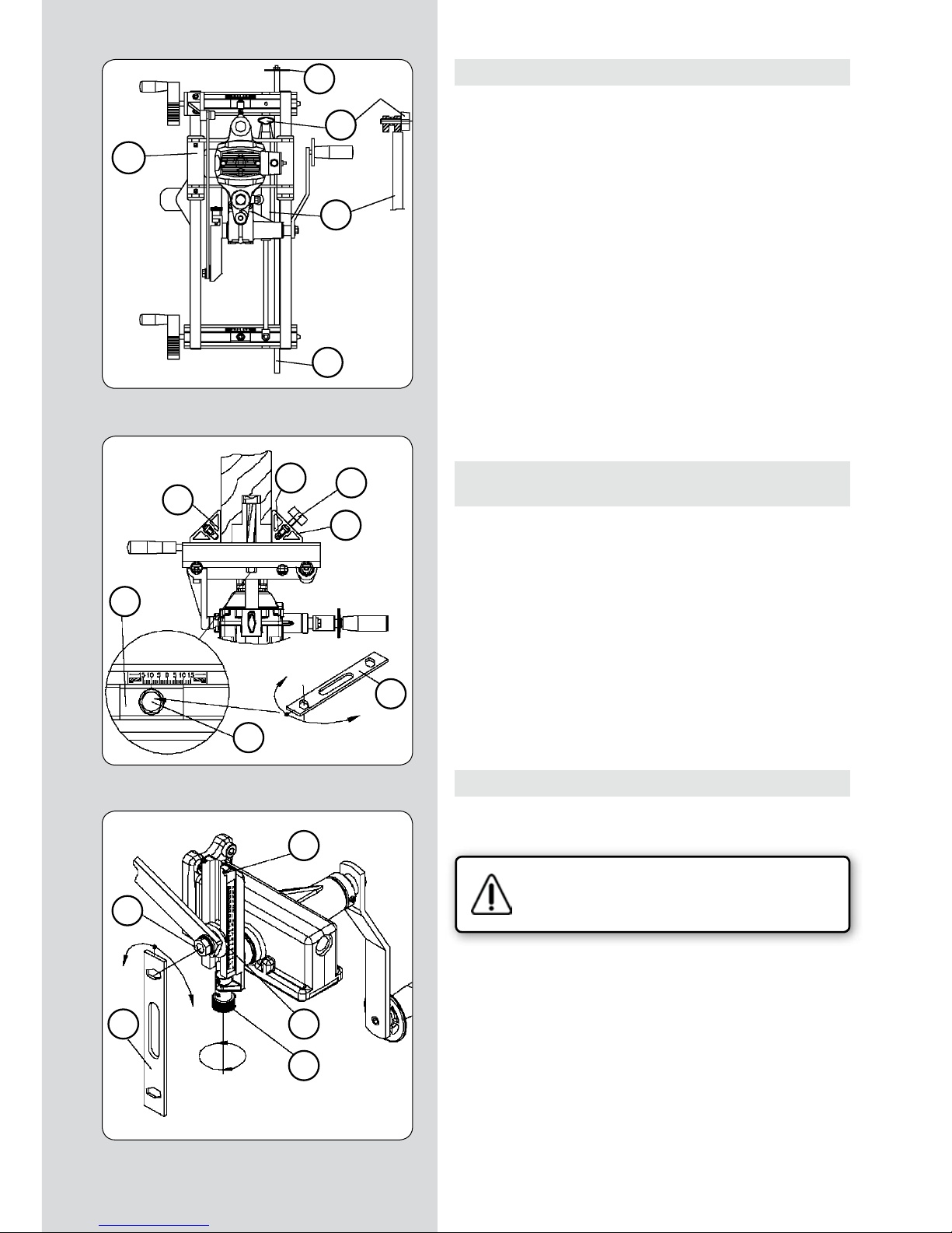
44 - FC116U / Mode d’emploi
14. FRAISAGE DE LA MORTAISE SUR PLUSIEURS PORTES
• Si on veut mortaiser plusieurs portes et situer les serrures à
la même hauteur, il est conseillé d’employer la tige de hauteurs
“A1” (Fig. 21) qui facilitera l’opération.
Pour ce faire, après avoir déterminé la hauteur de la serrure sur la
première porte, et situé la machine en position pour fraiser, monter les quatre tiges de hauteur “A1” (Fig. 21) et les insérer dans
les orifices des étaus “X” (Fig. 22), de manière à ce que le disque
de butée “A2” (Fig. 21) de leur extrémité fasse butée sur le chant
supérieur de la porte et fixer la tige de hauteur “A1” (Fig. 21 et 22)
dans cette position, avec les boutons “B1” (Fig. 22). Pour la porte
suivante, il n’y aura qu’à placer la machine, avec le disque de butée
“A2” (Fig. 21) de la tige de hauteur “A1” reposant sur le chant
supérieur de la porte, puis à fixer les étaux dans cette position
et à marquer le trait de repère supérieur “rs” pour l’utiliser par la
suite sur cette nouvelle porte, ce qui permettra de poser toutes les
serrures à la même hauteur.
On peut également employer la tige de hauteurs “A1” (Fig. 21) sans
le disque de butée “A2” (Fig. 21) comme référence de hauteur par
rapport au sol.
15. FRAISAGE DE MORTAISAGES
EN POSITION HORIZONTALE
• Pour travailler avec la FC116U en position horizontale, par
exemple pour la réalisation de mortaises sur portes avant de les
monter, il convient de déconnecter l’amortisseur “T1”, (Fig. 21),
pour libérer le mouvement du chariot “U1”.
Pour ce faire, dévisser l’ecrou “P” (Fig. 23) avec la clé “F” et en
actionnant le bouton à vis “R”, déplacer l’indicateur de longueur
“S” jusqu’à la butée “A2” de fin de course.
Retirer le bouton “S1” (Fig. 21) qui fixe l’amortisseur “T1” pour
le déconnecter. Garder le bouton “S1” dans un endroit sûr pour
une prochaine utilisation. Pour terminer, régler la longueur de
fraisage voulue, selon ce qui est indiqué au paragraphe 9, avant
de travailler avec la machine, car elle ne doit jamais travailler en
fin de course, au-delà de la longueur maximum.
16. CORRECTIONS POUR PORTES À CHEVAUCHEMENT
Pour le mortaisage de portes à chevauchement, il faudra corriger
le centrage de la machine et la profondeur de fraisage comme suit:
Vérifier si la machine est bien débranchée du
secteur.
• Pour centrer la machine, sur la section de porte sans chevauchement, desserrer avec la clé “F” (Fig. 22) les vvis “Q” qui bloquent les étaus “X” et déplacer les plaques “J” vers le côté du
chevauchement de la moitié de la largeur de celui-ci en mm, et
fixer à nouveau les vis “Q” dans cette position.
• En réglant la profondeur de fraisage, comme cela est expliqué
au paragraphe 10, il faudra situer l’anneau de butée “A” (Fig. 8)
à une hauteur de l’échelle “U” (Fig. 8) qui soit la somme de la
profondeur nécessaire pour la serrure plus la hauteur du chevauchement de la porte, puisque la machine s’appuiera sur ce
chevauchement.
(Figure 21)
(Figure 22)
(Figure 23)
S1
A2
U1
T1
A1
A2
P
F
R
S
X
A1
B1
X
J
F
Q
Page 45
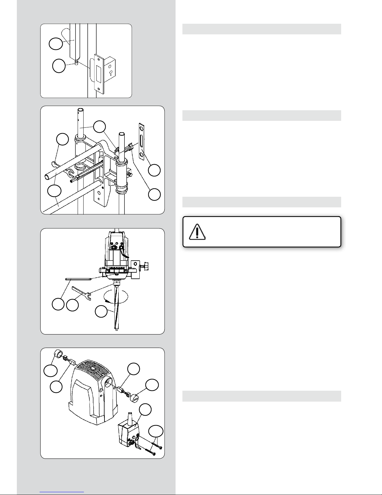
FC116U / Mode d’emploi - 45
17. KIT D'ASPIRATION
• La mortaiseuse FC116U dispose d’une buse “D2” (Fig. 24) qui,
montée sur la tige de position “D1” (Fig. 24), sur l’ouverture du
logement à réaliser, permet de brancher l’Aspirateur Virutex
AS182K, AS282K, AS382L et ASC482U ou un autre aspirateur
industriel pour l’évacuation des copeaux du fraisage.
18. EXTRACTION DE L'AXE CANNELÉ
Pour changer l’axe cannelé “M” (Fig. 26), démonter tout d’abord
la fraise “G” (Fig. 25) comme cela est expliqué au paragraphe 6.
Placer la clavette “L” (Fig. 26) dans l’orifice central de la carcasse,
jusqu’à ce que l’axe du moteur se bloque puis extraire l’axe cannelé “M” avec la clé “E”.
19. CHANGEMENT DES BALAIS
Vérifier si la machine est bien débranchée du
secteur avant de faire toute manipulation.
• Les balais doivent être changés quand ils ont une longueur
minimum de 5 mm. Pour ce faire, démonter le boîtier de
l’interrupteur “F1” (Fig. 27) en retirant les vis “G1” qui le fixent.
Retirer les bouchons “H1” qui fixent les balais “I1” et les remplacer par d’autres d’origine VIRUTEX, en vérifiant qu’ils glissent
doucement à l’intérieur des guidages. Vérifier, en remontant le
boîtier de l’interrupteur “F1”, que les câbles sont bien situés à
l’intérieur.
Il est conseillé de laisser la machine en marche à vide pendant
quelques minutes après avoir remplacé les balais. Profiter du
changement des balais pour vérifier l’état du collecteur. Si celuici présente des brûlures ou des ressauts, il est conseillé de le faire
réparer par un Service Technique VIRUTEX.
20. LUBRIFICATION ET NETTOYAGE
• Avant de fraiser le premier délardement, lubrifier les colonnes
de guidage de profondeur “Gp” (Fig. 25) et les transversales “Gt”
(Fig. 25) avec un chiffon légèrement imprégné d’huile pour faciliter les deux mouvements. Il est cependant important de toujours nettoyer soigneusement la machine après son utilisation,
avec un souffle d’air sec.
Toujours conserver le câble d’alimentation dans de parfaites
conditions d’emploi.
(Figure 25)
(Figure 24)
(Figure 26)
(Figure 27)
E
D2
D1
F
G
L
E
M
Gt
Gp
F1
G1
H1
I1
I1
H1
Page 46
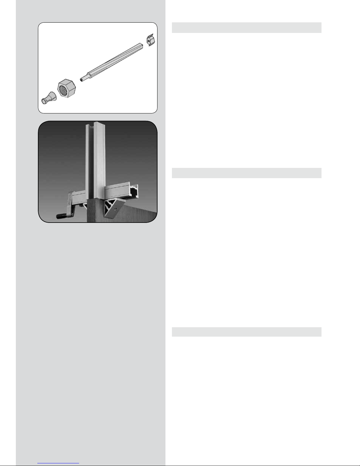
46 - FC116U / Mode d’emploi
21. OUTILS ET ACCESSOIRES OPTIONNELS
• Fraises pour mortaiseuse FC16S disponibles:
NUMÉRO DIAM.EXT. HAUTEUR
1640127 16 mm. 13.5 mm.
1640150 17 “ 13.5 “
1640128 18 “ 13.5 “
1640367 20 “ 13.5 “
1640129 21 “ 13.5 “
1640130 23 “ 13.5 “
1640368 23,5 “ 13.5 “
1640131 25 “ 13.5 “
1640369 29 “ 13.5 “
1640132 30 “ 13.5 “
1640140 Fraise à percer Ø 24
• La rallonge UP16I, 1645287, permet de rallonger la fixation de
la machine au-delà de la porte.
22. NIVEAU DE BRUIT
Les niveaux de bruit et de vibrations de cet appareil électrique ont été mesurés conformément à la norme européenne EN
61029-1 et font office de base de comparaison avec des machines aux applications semblables.
Le niveau de vibrations indiqué a été déterminé pour les principales applications de l’appareil, et il peut être pris comme valeur
de base pour l’évaluation du risque lié à l’exposition aux vibrations. Toutefois, dans d’autres conditions d’application, avec
d’autres outils de travail ou lorsque l’entretien de l’appareil électrique et de ses outils est insuffisant, il peut arriver que le niveau
de vibrations soit très différent de la valeur déclarée, voire même
beaucoup plus élevé en raison du cycle de travail et du mode
d’utilisation de l’appareil électrique.
Il est donc nécessaire de fixer des mesures de sécurité pour protéger l’utilisateur contre les effets des vibrations, notamment garder l’appareil et les outils de travail en parfait état et organiser
les temps des cycles de travail (temps de fonctionnement avec
l’appareil en service, temps de fonctionnement avec l’appareil à
vide, sans être utilisé réellement), car la diminution de ces temps
peut réduire substantiellement la valeur totale d’exposition.
23. GARANTIE
Toutes les machines électroportatives VIRUTEX ont une garantie valable 12 mois à partir du jour de la fourniture, étant exclus toutes les manipulations ou les dommages causés par des
maniements incorrects ou provenant de l’usure naturelle de la
machine. Pour toute réparation, s’adresser au Service Officiel
d’Assistance Technique VIRUTEX.
VIRUTEX se réserve le droit de modifier ses produits sans avis
préalable.
Page 47

FC116U / Gebrauchsanweisung - 47
INDEX
Spezifikationsänderungen
vorbehalten.
GEBRAUCHSANWEISUNG
1 TECHNISCHE DATEN 48
2 EINSATZ 48
3 SICHERHEITSHINWEISE ZUM GE-
BRAUCH DER MASCHINE 49
4 STANDARDAUSRÜSTUNG 49
5
MONTAGE DER SCHLITTENVORSCHUBKURBEL
49
6 MONTAGE DER SCHNEIDWERKZEUGE 50
7 SCHALTER 50
8 EINSTELLUNG DER FRÄSBREITE 50
9 EINSTELLUNG DER FRÄSLÄNGE 51
10 EINSTELLUNG DER FRÄSTIEFE 51
11 LANGLOCHFRÄSUNG AN EINER TÜR 52
BEZUGSLINIEN MESSEN UND ZEICHNEN 52
FRÄSEN DES SCHLOSSKASTENS 53
12.1 FRÄSEN DES SITZES FÜR DIE FRONTPLATTE
DES SCHLOSSES FÜR "Nt" MAX. 170 mm 54
AUSTAUSCHEN DER FRÄSE 54
BEZUGSLINIEN MESSEN, ZEICHNEN UND
FC116U AN DER TÜR BEFESTIGEN 54
EINSTELLEN DES FRÄSWEGS 54
EINSTELLEN DER FRÄSTIEFE 55
FRÄSEN DES SITZES 55
12.2 FRÄSEN DES SITZES FÜR DIE FRONTPLATTE
DES SCHLOSSES FÜR "Nt" ÜBER 170 mm 56
AUSTAUSCHEN DER FRÄSE 56
MESSEN UND ANZEICHNEN 56
EINSTELLEN DES FRÄSWEGS 56
EINSTELLEN DER FRÄSTIEFE 56
FRÄSEN DES SITZES 57
13 BOHREN DER ÖFFNUNGEN FÜR DIE
TÜRKLINKE UND DEN SCHLÜSSEL 58
ANBRINGEN DER VORRICHTUNG VON
SCHABLONE UC16I 58
POSITIONIEREN DER VORRICHTUNG UND
BOHREN 58
OPTIONALE BOHRWERKZEUGE 58
14
FRÄSEN DES SCHLOSSKASTENS AN MEHREREN TÜREN
59
15
LANGLOCHFRÄSUNG IN WAAGERECHTER
LAGE
59
16
KORREKTUREN BEI ÜBERL APPENDEN TÜREN
59
17 ANSCHLUSS EINES STAUBSAUGERS 60
18 AUSBAU DER GEKEHLTEN ACHSE 60
19
AUSWECHSELN DER STROMABNEHMER
60
20 SCHMIERUNG UND REINIGUNG 60
21 WERKZEUGE UND SONDERZUBEHÖR 61
22 LÄRMPEGEL 61
23 GARANTIE 61
Page 48
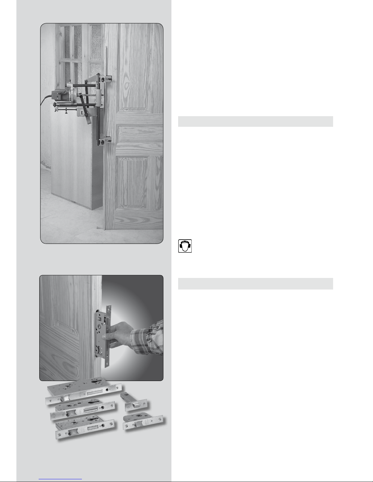
48 - FC116U / Gebrauchsanweisung
LANGLOCHFRÄSMASCHINE FC116U
BITTE BEACHTEN
Lesen Sie bitte vor Benutzung der Maschine die beiliegende GEBRAUCHSANWEISUNG und die ALLGEMEINEN SICHERHEITSHINWEISE sorgfältig durch.
Stellen Sie sicher, dass Sie sowohl die Gebrauchsanweisung als
auch die allegemeinen Sicherheitshinweise verstanden haben,
bevor Sie die Maschine bedienen. Bewahren Sie beide Gebrauchsanweisungen zum späteren Nachschlagen auf.
1. TECHNISCHE DATEN
Universal-Motor............................................................................50/60 Hz
Leistung.............................................................................................1.100 W
Leerlaufgeschwindigkeit.....................................................23.000 min
-1
Maximaler Fräserdurchmesser......................................................30 mm
Maximale Frästiefe....................................................................0 - 125 mm
Maximale Fräsbreite..................................................Fräserdurchmesser
Maximale Fräslänge...............................177 mm + Fräserdurchmesser
Maximale Backenöffnung..........................................................190 mm
Kleinstübermaß der Backen.............................................................13 mm
Seitliche Verschiebung des Fräsers über die Türstärke..........± 15 mm
Gewicht.................................................................................................14 Kg
Gewichteter akustischer Dauerdruckpegel A........................87 dBA
Akustischer Druckpegel A..........................................................98 dBA
Unsicherheit......................................................................................K = 3 dBA
Gehörschutz tragen!
Schwingungsgesamtwerte................................................a
h
: <2,5 m/s
2
Unsicherheit............................................................................K = 1,5 m/s
2
2. EINSATZ
Die Hand-Langlochfräsmaschine FC116U ist ein elektrisches
Werkzeug zum Fräsen von Schlitzen zum Befestigen von Türschlössern, Zapfenlochverbindungen, etc.
Zusätzlich zum Fräsen von Schlosskästen lässt sich auch der Sitz
der Frontplatte des Schlosses und der Sitz des Schließblechs am
Rahmen fräsen. Mithilfe des mitgelieferten Werkzeugs UC16I
können die Bohrungen für die Falle oder das Schlüsselloch sowie
für die Türklinke gebohrt werden.
Page 49

FC116U / Gebrauchsanweisung - 49
3. SICHERHEITSHINWEISE ZUM GEBRAUCH DER MASCHINE
Vergewissern Sie sich, daß sich der Benutzer dieser Maschine vor der ersten Verwendung sorgfältig und eingehend diese GEBRAUCHSANWEISUNG
und das beigefügte MERKBLATT ZU ALLGEMEINEN SICHERHEITSMASSNAHMEN durchliest.
• Prüfen Sie vor dem Einschalten der Maschine, ob die Versorgungsspannung mit der Angabe auf dem Typenschild übereinstimmt.
• Zum Auswechseln des Fräsers oder zur Durchführung anderer
Arbeiten am Schneidkopf ziehen Sie den Netzstecker.
• Benutzen Sie eine Schutzbrille bei der Arbeit mit der Fräsmaschine.
• Schalten Sie nicht den Motor ein, wenn er aus dem Gehäuse
herausmontiert wurde.
• Überprüfen Sie den Weg des Versorgungskabels, um zu verhindern, daß es sich während der Arbeit verheddert.
• Schalten Sie die Fräsmaschine immer über den Hebel des
Hauptschalters ein.
• Sobald sich die Fräsmaschine auf dem zu fräsenden Werkstück
befindet, führen Sie grundsätzlich den Vorschub der Maschine
mit der Handkurbel am Schlitten durch. Helfen Sie niemals mit
den Händen oder mit anderen Werkzeugen nach.
• Vergewissern Sie sich immer, daß der Motor völlig zum Stillstand gekommen ist, bevor Sie die Fräsmaschine aus dem Langloch herausziehen.
• Benutzen Sie immer Fräser mit einem geeigneten Durchmesser
und montieren Sie sie korrekt an der gekehlten Achse.
• Benutzen Sie niemals ungeeignete, schadhafte oder abgenutzte Fräser. Benutzen Sie ausschließlich Original-Fräser und -Ersatzteile von VIRUTEX.
4. STANDARDAUSRÜSTUNG
In der Schachtel finden Sie folgende Teile:
• Langlochfräsmaschine FC116U
• Werkzeug zum Bohren der Bohrungen für das Schlüsselloch
und die Klinkenachse UT16I
• Montageschlüssel und Zeichenschablone
• Einen vierteiligen, auseinandernehmbaren Höhenstab und einen Türanschlag.
•
Vier Backenschützer für Arbeiten auf empfindlichen Oberflächen.
• Langlochfräser mit 16 mm Durchmesser.
• Betriebsanleitung und verschiedene Unterlagen
5. MONTAGE DER SCHLITTENVORSCHUBKURBEL
Vergewissern Sie sich, daß die Fräsmaschine von
der elektrischen Stromversorgung getrennt ist.
• Rasten Sie die rechtwinkelige Nut der Vorschubkurbel des Schlittens “A” ein, sodass der Schlitten zu den Ebenen der Achse “B” zeigt.
Anschließend setzen Sie die Scheibe “C” und die Schraube “D” ein
(Abb. 1). Ziehen Sie mit dem Schlüssel “F” die Schraube “D” an, sodass die Vorschubkurbel des Schlittens in ihrer Aufnahme fest sitzt.
• SCHLAGEN SIE NICHT GEGEN DIE OBERFLÄCHE DER VORSCHUBKURBEL “A”.
Fig. 1
(Abb. 1)
Page 50
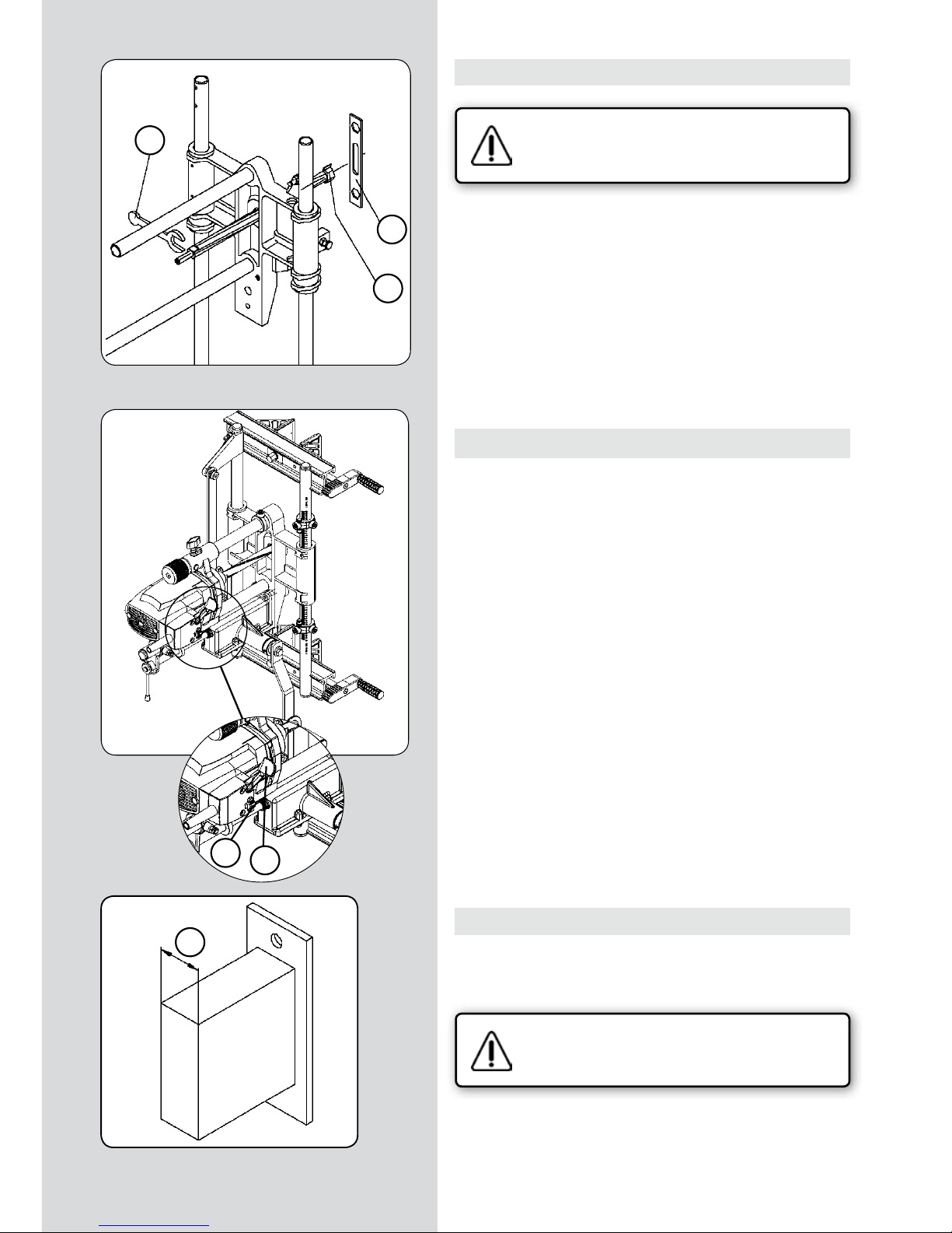
50 - FC116U / Gebrauchsanweisung
6. MONTAGE DER SCHNEIDWERKZEUGE
Überprüfen Sie, ob die Fräsmaschine von der
Stromversorgung getrennt ist.
• Die Langlochfräsmaschine wird mit einem Fräser mit einem
Durchmesser von 16 mm am Ende der gekehlten Achse geliefert.
Zum Wechseln des Fräsers blockieren Sie die gekehlte Achse auf
ihren Planseiten mit dem Schlüssel “E” (Abb. 2), schrauben Sie
den Fräser “G” mit dem Schlüssel “F” ab und ersetzen Sie ihn
durch einen mit dem gewünschten Durchmesser.
7. SCHALTER
• Das Schaltergehäuse (Abb. 7), ist mit einem Hebel “Y” zum
Starten der Maschine und einer seitlichen Sperrsicherung “Z”
versehen. Zum Starten betätigt man die Sperrsicherung “Z” und
drückt, ohne loszulassen, den Hebel “Y”, um die Maschine in Betrieb zu halten.
Wenn man den Hebel “Y” bei laufender Maschine drückt, löst
sich automatisch die Sicherung “Z” und die Maschine hält an.
Die Sperrsicherung des Schalters “Z” verhindert die unbeabsichtigte Inbetriebnahme der Maschine.
8. EINSTELLUNG DER FRÄSBREITE
• Messen Sie den breitesten Punkt “N” des Schlosses einschließlich aller möglichen vorstehenden Teile (Abb. 4). NEHMEN
SIE NICHT die äußere Blendenseite des Schlosses mit hinzu.
Vergewissern Sie sich, daß die Fräsmaschine von
der elektrischen Stromversorgung getrennt ist.
• Verwenden Sie einen Langlochfräser mit dem genommenen
Maß oder mit einem etwas größeren und montieren Sie ihn nach
den Anweisungen in Abschnitt 6.
(Abb. 4)
(Abb. 2)
(Abb. 3)
Y
E
Z
N
G
F
Page 51

FC116U / Gebrauchsanweisung - 51
9. EINSTELLUNG DER FRÄSLÄNGE
• Messen Sie den längsten Punkt “H” des Schlosses einschließlich
aller möglichen vorstehenden Teile (Abb. 5). NEHMEN SIE NICHT
die äußere Blendenseite des Schlosses mit hinzu.
Vergewissern Sie sich, daß die Fräsmaschine von
der elektrischen Stromversorgung getrennt ist.
• Zur Anpassung der Maschine an die gewünschte Fräslänge “H”
lösen Sie die Mutter “P” (Abb. 6) mit dem Schlüssel “F” und betätigen Sie den Spindelknauf “R”, bis die Längenanzeige “S” das
gewünschte Maß “H” erreicht und ziehen Sie die Mutter “P” in
dieser Stellung fest.
Vergewissern Sie sich, daß Sie die Mutter “P”
(Abb. 6) festgezogen haben, da sonst der Mechanismus zum Einstellen der Fräslänge zerstört
werden kann.
Das Zentrieren des Fräsers auf die Stärke der Tür oder des zu
fräsenden Teils geschieht automatisch, wenn die Plättchen “J”
(Abb. 7) an den beiden Backenführungen “V” in der Stellung “0”
(Abb. 7) sind.
10. EINSTELLUNG DER FRÄSTIEFE
• Messen Sie die Tiefe “T” (Abb. 5) des Schlosses einschließlich
aller möglichen vorstehenden Teile an der Unterseite und der
Stärke der äußeren Blendenseite und geben Sie einige Millimeter
Spiel hinzu.
Vergewissern Sie sich, daß die Fräsmaschine von
der elektrischen Stromversorgung getrennt ist.
• Die Frästiefe wird über die Meßschiene “U” (Abb. 8) eingestellt, die in 1-mm-Abstände unterteilt ist. Lösen Sie den Knauf
“W” und setzen Sie den Ring “A” so an, daß seine Unterseite mit
der gewünschten Tiefe übereinstimmt, und ziehen Sie den Knauf
“W” in dieser Stellung wieder fest.
(Abb. 6)
(Abb. 8)
(Abb. 5)
T
H
F
R
P
S
W
A
U
(Abb. 7)
J
V
V
V
A
W
Page 52
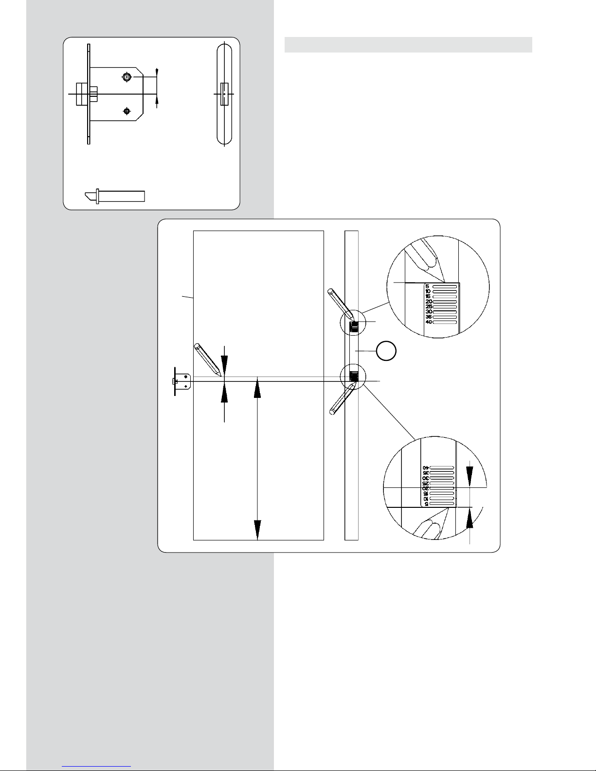
52 - FC116U / Gebrauchsanweisung
11. LANGLOCHFRÄSUNG AN EINER TÜR
• Stellen Sie die Tür vertikal und halten Sie sie fest, so daß sie
sich nicht bewegen kann. Wenn sich die Tür bereits eingebaut
im Rahmen befindet, schieben Sie Keile darunter, so daß sie sich
nicht bewegen kann.
BEZUGSLINIEN MESSEN UND ZEICHNEN
• Legen Sie das Schloss so an der Tür an, dass das Loch für die
Klinke auf der gewünschten Höhe ab Boden “H0” liegt (Abb. 9)
und zeichnen Sie eine Bezugslinie “0” (Abb. 9) auf dem Türblatt
und auf der Kante.
• Messen Sie den Abstand “H2” (Abb. 9) von der Mitte der Klinke
bis zur Mitte des Schlosskastens.
• Zeichnen Sie die Mitte “c” des Schlosskastens auf die
Türkante. Verwenden Sie dazu die mitgelieferte Zeichenschablone “Pt” (Abb. 9).
Diese Schablone verfügt über eine Reihe von Schlitzen in einem
jeweiligen Abstand von 5 mm. Legen Sie die Schablone so an der
Türkante an, dass die Linie “0” (Abb. 9) mit dem Schlitz übereinstimmt, der dem Maß “H2” (Abb. 9) entspricht, das sie vorher
gemessen haben (20 mm in Abb. 9). Zeichnen Sie nun die Linie
“c” (Abb. 9) am unteren Rand der Schablone.
• Zeichnen Sie die obere Bezugslinie “rs” (Abb. 9), die als
Referenz für das Anbringen der Maschine auf der Tür dient.
Legen Sie dazu das untere Ende der Zeichenschablone “Pt” (Abb.
9) auf die Linie “c” (Abb. 9) und zeichnen Sie die Bezugslinie “rs”
(Abb. 9) am oberen Ende der Schablone.
(Abb. 9)
Pt
"c"
"H2"
"rs"
"H2"
"0"
"rs"
"rs"
"c"
"H0"
"0"
"c"
"c"
"c"
"0"
"H2"
Page 53

FC116U / Gebrauchsanweisung - 53
FRÄSEN DES SCHLOSSKASTENS
• Halten Sie die Maschine auf die Tür und richten Sie das Rahmenoberstück “V” (Abb. 10) mit der oberen Linie “rs” (Abb. 10)
aus. Befestigen Sie die Backen, indem Sie die Kurbeln “K” (Abb.
10) fest anziehen.
• Überprüfen Sie, ob sich die Vorschubkurbel “A” (Abb. 10) auf
der gesamten Fräslänge frei bewegen kann.
• Drehen Sie den Feststellstift “J” (Abb. 10) in die vertikale Stellung, damit der Vorschubmechanismus für die Frästiefe eingreifen kann.
• Schließen Sie die Maschine an der Stromversorgung an, schalten Sie den Motor durch Drücken des Hebels “Y” (Abb. 10) ein
und rasten Sie die Sicherheitsverriegelung “Z” (Abb. 10) ein.
• Drehen Sie wiederholt die Vorschubkurbel “A” (Abb. 10), wodurch Sie einen synchronisierten Vorschub des Werkzeuges in
der Länge und in der Tiefe bis zum in Abschnitt 10 festgelegten
Fräsende erreichen.
• Bringen Sie durch Betätigen des Hebels “Y” die Maschine zum
Stillstand (Abb. 10).
Trennen Sie die Fräsmaschine vom elektrischen
Stromnetz.
• Drehen Sie den Feststellstift “J” (Abb. 10) in die horizontale
Stellung, damit der Vorschubmechanismus des Werkzeugs gelöst
wird und der Motor bis zum Ende des Fräswegs zurückkehrt.
(Abb. 10)
V
Y
K
J
Z
A
"rs"
"c"
Page 54

54 - FC116U / Gebrauchsanweisung
12.1. FRÄSEN DES SITZES FÜR DIE FRONTPLATTE DES
SCHLOSSES FÜR "Nt" MAX. 170 mm
Vergewissern Sie sich, daß die Fräsmaschine von
der elektrischen Stromversorgung getrennt ist.
AUSTAUSCHEN DER FRÄSE
• Messen Sie die Breite “N1” (Abb. 11) der Front des Schlosses
und installieren Sie in der Maschine eine Langlochfräse des entsprechenden Maßes. Halten Sie sich dazu an die Anleitungen in
Abschnitts 6 des Handbuchs.
BEZUGSLINIEN MESSEN, ZEICHNEN UND FC116U AN DER
TÜR BEFESTIGEN
• Messen Sie die Distanzen zwischen dem Schlosskasten und beiden Enden der Frontplatte des Schlosses “N2” und “N3” (Abb. 11).
• Wenn beide Maße “N2” und “N3” (Abb. 11) gleich sind: Halten Sie die Maschine auf die Tür und richten Sie das Rahmenoberstück “V” (Abb. 12) mit der oberen Bezugslinie “rs” (Abb.
12) aus. Dadurch bleiben die Zentren des Maschinenhubs, des
Schlosskastens und der Frontplatte des Schlosses ausgerichtet.
• Wenn die Maße “N2” und “N3” (Abb. 11) nicht gleich sind, nehmen Sie die Differenz zwischen beiden Maßen “N2”-“N3”=X mm
(Abb. 11). Zeichnen Sie eine neue obere Bezugslinie “rs1” (Abb.
13 und 12), die um X mm in Richtung des größeren Maßes von
“N2” und “N3” verschoben ist. Halten Sie anschließend die Maschine auf die Tür und richten Sie das Rahmenoberstück “V” (Abb.
12) auf die obere Bezugslinie “rs1” (Abb. 12) aus. Dadurch bleiben die Zentren des Maschinenhubs, des Schlosskastens und der
Frontplatte des Schlosses ausgerichtet.
EINSTELLEN DES FRÄSWEGS
• Messen Sie die Länge der Stirnseite “NT” (Abb. 11) des Schlosses
und stellen Sie die zwei Längsanschläge “S1” (Abb. 12 und 14) auf
der Unterteilung fest, die dem Maß “NT” auf der Führungsstange
“S” (Abb. 14) entspricht.
• Legen Sie die zwei Anschläge zum Ausgleichen des Fräserdurchmessers “S2” (Abb. 14) auf der Markierung an, die dem Durchmesser des montierten Fräsers entspricht (Abb. 14).
• Stellen Sie auf der Schubstange die Länge des Fräswegs auf
eine Länge ein, die etwas länger als die Stirnseite des Schlosses “NT” (Abb. 11) ist. Siehe hierzu Abschnitt 9 (Abb. 6) dieses
Handbuchs.
N1
N2-N3= X mm
N2-N3= X mm
S1
V
"rs"
"rs1"
"rs"
"rs1"
"N3"
"Nt"
"N2"
(Abb. 11)
(Abb. 12)
(Abb.13)
(Abb. 14)
S2
S1
S
Page 55

FC116U / Gebrauchsanweisung - 55
EINSTELLEN DER FRÄSTIEFE
• Heben Sie den Feststellknopf “W” (Abb. 15 - 18) bis in seine
höchste Position, indem sie ihn im Gegenuhrzeigersinn drehen.
• Stellen Sie sicher, dass der Feststellstift “J” (Abb. 15) in der
horizontalen Stellung ist (Tiefenvorschub ausgeschaltet).
• Lösen Sie den Griff “K” (Abb. 16). Verschieben Sie die Maschine
durch sanften Druck mit der Hand auf den Motor nach unten, bis
die Fräse die Türkante berührt. Halten Sie sie in dieser Position
fest und ziehen Sie den Feststellknopf “K” (Abb. 16) an.
• Legen Sie Stirnseite des Schlosses (Abb. 17) an und berühren
Sie dabei den unteren Bereich der Motorhalterung. Verschieben
Sie den Tiefenanschlag “S3” (Abb. 16 und 17) und klemmen Sie
die Stirnseite des Schlosses ein.
• Lösen Sie den Feststellknopf “K” (Abb. 15 - 17), damit die Maschine in ihre Startposition gehoben wird.
FRÄSEN DES SITZES
• Stellen Sie sicher, dass der Feststellstift “J” (Abb. 15) in der
horizontalen Stellung ist (Tiefenvorschub ausgeschaltet).
• Schließen Sie die Maschine an der Stromversorgung an, schalten Sie den Motor durch Drücken des Hebels “Y” (Abb. 18) ein
und rasten Sie die Sicherheitsverriegelung “Z” (Abb. 18) ein.
• Drehen Sie den Feststellknopf “W” (Abb. 17 und 18), bis die
Motorhalterung den Tiefenanschlag “S3” berührt (Abb. 18). Sobald das Werkzeug die für die Frontplatte des Schlosses vorgesehene Frästiefe erreicht hat, betätigen Sie sanft in einer Hinund Herbewegung die Vorschubkurbel des Wagens “A” (Abb. 15
und 18), bis die beiden Anschläge “S1” am Anfang und Ende des
Fräswegs (Abb. 15 und 18) erreicht worden sind.
Wenn der zu fräsende Sitz tiefer als 2 mm ist, wird empfohlen,
den Vorgang in zwei oder mehreren aufeinander folgenden Durchgänge auszuführen und dabei wiederholt den Feststellknopf
“W” zu betätigen.
• Stellen Sie nach Beenden des Fräsvorgangs am Feststellknopf
“W” (Abb. 18) und am Tiefenanschlag “S3” (Abb. 16) wieder die
Grundeinstellungen ein.
(Abb. 15)
(Abb. 16)
(Abb. 17)
(Abb. 18)
K
W
S1
A
J
rs
W
K
S3
W
K
S3
S3
W
A
Z
Y
S1
rs1
Page 56

56 - FC116U / Gebrauchsanweisung
12.2. FRÄSEN DES SITZES FÜR DIE FRONTPLATTE DES
SCHLOSSES FÜR "Nt" ÜBER 170 mm
Vergewissern Sie sich, daß die Fräsmaschine von
der elektrischen Stromversorgung getrennt ist.
AUSTAUSCHEN DER FRÄSE
• Messen Sie die Breite “N1” (Abb. 11.2) der Front des Schlosses
und installieren Sie in der Maschine eine Langlochfräse des entsprechenden Maßes. Halten Sie sich dazu an die Anleitungen in
Abschnitts 6 des Handbuchs.
MESSEN UND ANZEICHNEN
• Legen Sie das Schloss in den Sitz für den Schlosskasten und
zeichnen Sie die beiden Enden der Frontplatte auf der Türkante
an (Abb. 12.2 und 13.2).
EINSTELLEN DES FRÄSWEGS
• Stellen Sie auf der Schubstange die Länge des Fräswegs auf
170 mm ein. Siehe hierzu Abschnitt 9 (Abb. 6) dieses Handbuchs.
• Fixieren Sie die zwei Längsanschläge “S1” (Abb. 12.2 und
14.2) auf der Skala der Führungsstange “S” (Abb. 14.2) auf dem
160 mm entsprechenden Teilstrich.
EINSTELLEN DER FRÄSTIEFE
• Stellen Sie die Frästiefe gemäß der Beschreibung im Abschnitt
12.1 dieses Handbuchs ein.
N1
S1
"Nt"
(Abb. 11.2)
(Abb. 12.2)
(Abb. 13.2)
(Abb. 14.2)
S2
S1
S
Page 57

FC116U / Gebrauchsanweisung - 57
FRÄSEN DES SITZES
• Stellen Sie sicher, dass der Feststellstift “J” (Abb. 15.2) in der
horizontalen Stellung ist (Tiefenvorschub ausgeschaltet).
Fräsen des oberen Teils des Sitzes:
• Drehen Sie das Werkzeug von Hand, bis es sich in vertikaler
Stellung befindet (Abb. 16.2).
• Drehen Sie die Kurbel “A“ (Abb. 15.2) im Uhrzeigersinn (+),
bis der obere Anschlag “S1“ (Abb. 15.2) erreicht ist. Stellen Sie
sicher, dass die Kurbel in dieser Stellung verbleibt.
• Lösen Sie die Maschine von der Türkante und verschieben Sie
sie senkrecht auf dieser, bis die Oberkante des Werkzeugs mit
der oberen Bezugslinie der Frontplatte des Schlosses (Abb. 16.2)
abschließt. Befestigen Sie die Maschine erneut in dieser Position
auf der Kante.
• Schließen Sie die Maschine an der Stromversorgung an, schalten Sie den Motor durch Drücken des Hebels “Y” (Abb. 18.2) ein
und rasten Sie die Sicherheitsverriegelung “Z” (Abb. 18.2) ein.
• Drehen Sie den Feststellknopf “W“ (Abb. 18.2), bis die Motorhalterung den Tiefenanschlag “S3“ berührt (Abb. 18.2). Sobald
das Werkzeug die für die Frontplatte des Schlosses vorgesehene
Frästiefe erreicht hat, betätigen Sie die Vorschubkurbel “A“ des
Wagens (Abb. 15.2 und 18.2) sanft nach unten, bis der untere
Anschlag “S1“ (Abb. 15.2) erreicht ist.
Wenn der zu fräsende Sitz tiefer als 2 mm ist, wird empfohlen,
den Vorgang in zwei oder mehreren aufeinander folgenden Durchgänge auszuführen und dabei wiederholt den Feststellknopf
“W” zu betätigen.
Fräsen des unteren Teils des Sitzes:
• Drehen Sie das Werkzeug von Hand, bis es sich in vertikaler
Stellung befindet (Abb. 16.2).
• Drehen Sie die Kurbel “A“ (Abb. 15.2) im Gegenuhrzeigersinn
(-), bis der untere Anschlag “S1“ (Abb. 15.2) erreicht ist. Stellen
Sie sicher, dass die Kurbel in dieser Stellung verbleibt.
• Lösen Sie die Maschine von der Türkante und verschieben Sie
sie senkrecht auf dieser, bis die Unterkante des Werkzeugs mit
der unteren Bezugslinie der Frontplatte des Schlosses abschließt.
Befestigen Sie die Maschine erneut in dieser Position auf der
Kante.
• Schließen Sie die Maschine an der Stromversorgung an, schalten Sie den Motor durch Drücken des Hebels “Y” (Abb. 18.2) ein
und rasten Sie die Sicherheitsverriegelung “Z” (Abb. 18.2) ein.
• Drehen Sie den Feststellknopf “W“ (Abb. 18.2), bis die Motorhalterung den Tiefenanschlag “S3“ berührt (Abb. 18.2). Sobald
das Werkzeug die für die Frontplatte des Schlosses vorgesehene
Frästiefe erreicht hat, betätigen Sie die Vorschubkurbel “A“ des
Wagens (Abb. 15.2 und 18.2) sanft nach oben, bis der obere Anschlag “S1“ (Abb. 15.2) erreicht ist.
Wenn der zu fräsende Sitz tiefer als 2 mm ist, wird empfohlen,
den Vorgang in zwei oder mehreren aufeinander folgenden Durchgänge auszuführen und dabei wiederholt den Feststellknopf
“W” zu betätigen.
• Stellen Sie nach Beenden des Fräsvorgangs am Feststellknopf
“W” und am Tiefenanschlag “S3” (Abb. 18.2) wieder die Grundeinstellungen ein.
(Abb. 15.2)
(Abb. 16.2)
(Abb. 18.2)
K
W
S1
A
J
S3
W
A
Z
Y
S1
Page 58

58 - FC116U / Gebrauchsanweisung
13. BOHREN DER ÖFFNUNGEN FÜR DIE TÜRKLINKE UND
DEN SCHLÜSSEL
• Als letzten Schritt können mithilfe der mitgelieferten Schablonen UT16I die für die Montage des Schlosses erforderlichen Bohrungen, wie die Bohrungen für die Klinke, die Türverriegelung,
das Schlüsselloch usw. angebracht werden.
ANBRINGEN DER VORRICHTUNG VON
SCHABLONE UC16I
• Führen Sie eine der zerlegbaren Höhenmessstangen der Ausrüstung in die Öffnungen
“A” ein und verschieben Sie die Vorrichtung,
bis die Referenz “0” auf dem Zentrum “c” des
Schlosskastens liegt. (Abb. 19).
• Befestigen Sie sie mit dem Knauf “B” und
bringen Sie gleichzeitig die Innenseite “C” des
Führungsblechs bündig mit der Türkante in
Stellung. (Abb. 19).
POSITIONIEREN DER VORRICHTUNG UND
BOHREN
• Lösen Sie die Lagerbüchse “G” und verschieben Sie sie horizontal, bis die Anzeige “H” mit
dem Maß “D” ausgerichtet ist und ziehen Sie
sie wieder an. (Abb. 20).
• Verschieben Sie die Vorrichtung in Bezug auf
das Zentrum “c” des Schlosskastens in vertikaler Richtung, um es auf das gewünschte Maß
“E” und/oder “F” einzustellen. (Abb. 20)
• Nachdem die Position des Lochs festgelegt
ist, bohren Sie es mit einem Bohrer von 11 mm
Durchmesser.
• Wieder mit der Mitte “c” der Schloßaufnahme als Bezugspunkt kann nun ein weiteres
eventuell erforderliches Loch positioniert werden.
OPTIONALE BOHRWERKZEUGE
1640148 Erweiterungsfräser D.18 mit 11er-Führung
1640149 Erweiterungsfräser D.23 mit 11er-Führung
(Abb. 20)
(Abb. 19)
1640148
1640149
"c"
A
A
B
"c"
centro caja cerradura "c"
C
G
H
"c"
centro caja cerradura
centro caja cerradura "c"
"c"
Page 59
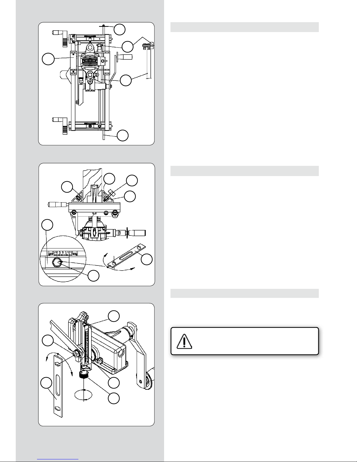
FC116U / Gebrauchsanweisung - 59
14. FRÄSEN DES SCHLOSSKASTENS AN MEHREREN TÜREN
• Wenn Sie mehrere Türen mit dem Schloß auf derselben Höhe
fräsen möchten, empfehlen wir Ihnen, den Höhenstab “A1” (Abb.
21) zu verwenden, der Ihnen die Arbeit erleichtern wird.
Dazu schrauben Sie nach Bestimmung der Schloßhöhe an der ersten Tür und mit der Maschine in der Fräsposition die vier Höhenstäbe “A1” (Abb. 21) an, setzen sie in die Öffnungen der Backen “X”
(Abb. 22), so daß die Anschlagsscheibe “A2” (Abb. 21) an ihrem
Ende an der oberen Türkante anschlägt, und drehen die Höhenstäbe “A1” (Abb. 21 und 22) mit den Knäufen “B1” (Abb. 22) in dieser Stellung fest. Für die folgende Türe müssen Sie lediglich noch
die Maschine mit der Anschlagscheibe “A2” (Abb. 21) der Höhenmessstange “A1” auf der oberen Türkante anlegen und die Spannbacken in dieser Position festziehen. Markieren Sie zudem für die
spätere Verwendung auf dieser neuen Tür die obere Bezugslinie
“rs”, damit alle Schlösser auf der gleichen Höhe zu liegen kommen.
Der Höhenstab “A1” (Abb. 21) kann auch ohne die Anschlagscheibe “A2” (Abb. 21) als Höhenreferenz bezüglich des Fußbodens eingesetzt werden.
15. LANGLOCHFRÄSUNG IN WAAGERECHTER LAGE
• Um mit der FC116U Langlochfräsungen in waagerechter Lage
durchzuführen, etwa bei Schlitzen für Schlösser an Türen, die erst
danach in den Rahmen gehängt werden, ist es ratsam, den Dämpfer “T1” (Abb. 21) außer Funktion zu setzen, damit der Schlitten “U1” sich ohne dessen Druck bewegt. Dafür lockern Sie die
Mutter “P” (Abb. 23) mit dem Schlüssel “F” und bewegen Sie die
Längenanzeige “S” durch Betätigen des Spindelknaufs “R” bis zum
Anschlag “A2” am Ende des Laufweges.
Entfernen Sie den Knauf “S1” (Abb. 21), der den Dämpfer “T1”
festhält, womit dieser außer Funktion gesetzt wird. Bewahren Sie
den Knauf “S1” für seine künftige Verwendung sorgfältig auf.
Stellen Sie abschließend, wie in Abschnitt 9 beschrieben, die
gewünschte Fräslänge ein, bevor Sie beginnen, mit der Maschine
zu arbeiten, da diese nie am Ende des Laufwegs, also über der
maximalen Fräslänge, arbeiten darf.
16. KORREKTUREN BEI ÜBERL APPENDEN TÜREN
Für das Langlochfräsen von Türen mit Überlappungen müssen Sie
die Zentrierung der Maschine und die Frästiefe folgendermaßen
korrigieren:
Vergewissern Sie sich, daß die Fräsmaschine von
der elektrischen Stromversorgung getrennt ist.
• Lösen Sie zum Zentrieren der Maschine am Türabschnitt ohne
Überlappung mit dem Schlüssel “F” (Abb. 22) die Schrauben “Q”,
die die Backen “X” blockieren, und verschieben Sie die Platten
“J1” um die Hälfte der Überlappungsbreite in mm in Richtung
der Überlappungsseite und ziehen Sie anschließend die Schrauben “Q” in dieser Stellung wieder fest.
• Beim Einstellen der Frästiefe wie in Abschnitt 10 erklärt müssen Sie den Anschlagring “A” (Abb. 8) auf eine Höhe der Skala
“U” (Abb. 8) bringen, die der Summe der notwendigen Tiefe für
das Schloß und der Höhe der Überlappung an der Tür entspricht,
da sich die Maschine auf der Überlappung bewegt.
(Abb. 21)
(Abb. 22)
(Abb. 23)
S1
A2
U1
T1
A1
A2
P
F
R
S
X
A1
B1
X
J
F
Q
Page 60

60 - FC116U / Gebrauchsanweisung
17. ANSCHLUSS EINES STAUBSAUGERS
• Die Langlochfräsmaschine FC116U verfügt über eine Mündung “D2” (Abb. 24), die am Positionsstab “D1” (Abb. 24) über
der zu fräsenden Aufnahme montiert den Anschluß des Virutex
Staubsaugers AS182K, AS282K, AS382L und ASC482U oder eines
anderen Industriestaubsaugers zur Absaugung von Frässpänen
erlaubt.
18. AUSBAU DER GEKEHLTEN ACHSE
Wenn Sie die gekehlte Achse “M” (Abb. 26) auswechseln wollen,
schrauben Sie zuerst den Fräser “G” (Abb. 25) wie in Abschnitt
6 erklärt ab.
Setzen Sie den Bolzen “L” (Abb. 26) in die mittlere Öffnung des
Gehäuses, bis die Motorachse blockiert ist und ziehen Sie die
gekehlte Achse “M” mit dem Schlüssel “E” heraus.
19. AUSWECHSELN DER STROMABNEHMER
Vergewissern Sie sich, daß die Maschine vor jeder Reparatur von der elektrischen Stromversorgung getrennt wird.
• Die Stromabnehmer müssen bei einer minimalen Länge von 5
mm ausgewechselt werden. Dazu schrauben Sie das Schaltergehäuse “F1” (Abb. 27) mit den Schrauben “G1” ab.
Nehmen Sie die Kappen “H1” ab, die die Stromabnehmer “I1”
festhalten und tauschen Sie diese durch Original Virutex-Stromabnehmer aus. Überprüfen Sie, ob sie sich ohne Probleme im
Innern der Führungen bewegen. Vergewissern Sie sich beim
Montieren des Schaltergehäuses “F1”, daß sich die Kabel im Innern nicht verheddern.
Es wird empfohlen, die Maschine nach dem Wechseln der Stromabnehmer einige Minuten leerlaufen zu lassen. Nutzen Sie den
Wechsel der Stromabnehmer zur Überprüfung des Kollektorzustandes. Sollte dieser Kontaktabbrand oder Ansätze aufweisen,
sollten Sie ihn zur Reparatur zu einem autorisierten VirutexHändler bringen.
20. SCHMIERUNG UND REINIGUNG
• Schmieren Sie vor dem Fräsen des ersten Sitzes die
Führungsstangen für die Tiefeneinstellung (Gp, Abb. 2) und die
Quereinstellung (Gt, Abb. 2) mit einem leicht geölten Lappen,
damit die beiden Bewegungen leichtgängig ausgeführt werden
können. Es ist wichtig, die Maschine nach der Verwendung immer gründlich mit Druckluft zu reinigen.
Halten Sie das Stromkabel immer in einem einwandfreien Zustand.
(Abb. 25)
(Abb. 24)
(Abb. 26)
(Abb. 27)
E
D2
D1
F
G
L
E
M
Gt
Gp
F1
G1
H1
I1
I1
H1
Page 61

FC116U / Gebrauchsanweisung - 61
21. WERKZEUGE UND SONDERZUBEHÖR
• Lieferbare Fräser für die Langlochfräsmaschine FC116U:
BEST.-NR. AUSSENDURCHMES SERHÖHE
1640127 16 mm. 13.5 mm.
1640150 17 “ 13.5 “
1640128 18 “ 13.5 “
1640367 20 “ 13.5 “
1640129 21 “ 13.5 “
1640130 23 “ 13.5 “
1640368 23,5 “ 13.5 “
1640131 25 “ 13.5 “
1640369 29 “ 13.5 “
1640132 30 “ 13.5 “
1640140 Bohrfräse Ø 24
• Mit der Verlängerungsvorrichtung UP16I, 1645287, kann die
Befestigung der Maschine über die Türe hinaus verlängert werden.
22. LÄRMPEGEL
Die Lärm- und Vibrationswerte dieses Elektrowerkzeugs wurden
in Übereinstimmung mit der europäischen Norm EN 661029-1
gemessen und dienen als Vergleichsgrundlage bei Maschinen für
ähnliche Anwendungen.
Der angegebene Vibrationspegel wurde für die wesentlichen
Einsatzzwecke des Werkzeugs ermittelt und kann bei der Beurteilung der Gefahren durch die Aussetzung unter Vibrationen
als Ausgangswert benutzt werden. Die Vibrationswerte können
sich jedoch unter anderen Einsatzbedingungen, mit anderen
Arbeitswerkzeugen oder bei einer ungenügenden Wartung des
Elektrowerkzeugs oder seiner Werkzeuge stark vom angegebenen Wert unterscheiden und aufgrund des Arbeitszyklus und der
Einsatzweise des Elektrowerkzeugs einen bedeutend höheren
Wert aufweisen.
Es ist daher erforderlich, Sicherheitsmaßnahmen zum Schutz des
Anwenders vor den Vibrationen festzulegen. Dazu können die
Aufrechterhaltung des einwandfreien Zustands des Werkzeugs
und der Arbeitsutensilien sowie die Festlegung der Zeiten der
Arbeitszyklen gehören (wie Laufzeiten des Werkzeugs unter Last
und im Leerlauf, ohne tatsächlich eingesetzt zu werden, wodurch die Gesamtzeit der Vibrationsauswirkungen bedeutend
verringert werden kann).
23. GARANTIE
Alle maschinen von VIRUTEX haben eine Garantie von 12 Monaten ab dem Lieferdatum. Hiervon ausgeschlossen sind alle Eingriffe oder Schäden aufgrund von unsachgemäßem Gebrauch
oder natürlicher Abnutzung des Geräts. Wenden Sie sich im Falle
einer Reparatur immer an den zugelassenen Kundendienst von
VIRUTEX.
VIRUTEX behält sich das Recht vor, die Produkte ohne vorherige
Ankündigung zu verändern.
Page 62

62 - FC116U / Manuale d’istruzioni
INDICE
Specifiche soggette a
cambiamento senza alcun
preavviso.
MANUALE D’ISTRUZIONI
1 SPECIFICHE TECNICHE 63
2 USO 63
3 ISTRUZIONI DI SICUREZZA PER L'USO
DELLA MACCHINA 64
4 APPARECCHIATURA STANDARD 64
5 MONTAGGIO DELLA MANOVELLA
AVANZAMENTO CARRELLO 64
6
MONTAGGIO DEGLI UTENSILI DA TAGLIO
65
7 INTERRUTTORE 65
8
REGOLAZ. DELLA LARGHEZZA DELLA FRESATURA
65
9
REGOLAZ. DELLA LUNGHEZZA DELLA FRESATURA
66
10
REGOLAZ. DELLA PROFONDITÀ DELLA FRESATURA
66
11
FRESATURA DI UNA MORTASA SU UNA PORTA
67
MISURARE E TRACCIARE RIFERIMENTI 67
FRESARE L’INCASSO DELLA SCATOLA 68
12.1
FRESATURA DELL’INCASSO PER LA
PIASTRA FRONTALE DELLA SERRATURA
PER "Nt" MASSIMO DI 170 mm 69
CAMBIARE LA FRESA 69
MISURARE, TRACCIARE RIFERIMENTI E POSIZIONARE FC116U SULLA PORTA 69
REGOLARE LA CORSA DELLA FRESATURA 69
REGOLARE LA PROFONDITÀ DI FRESATURA 70
FRESARE L’INCASSO 70
12.1
FRESATURA DELL’INCASSO PER LA
PIASTRA FRONTALE DELLA SERRATURA
PER "Nt" MAGGIORE DI 170 mm 71
CAMBIARE LA FRESA 71
MISURARE E TRACCIARE 71
REGOLARE LA CORSA DELLA FRESATURA 71
REGOLARE LA PROFONDITÀ DI FRESATURA 71
FRESARE L’INCASSO 72
13 REALIZZAZIONE DEI FORI PER LA MA-
NIGLIA E LA CHIAVE 73
MONTAGGIO DELL’UTENSILE DELLA DIMA
UC16I 73
DISPOSIZIONE DELL’UTENSILE E PERFORAZIONE 73
UTENSILI OPZIONALI PER FORATURA 73
14 FRESATURA DELL’INCASSO SU VARIE
PORTE 74
15 FRESATURA DI MORTASE IN POSIZIONE
ORIZZONTALE 74
16 CORREZIONI PER PORTE CON BATTUTA 74
17 KIT ASPIRATORE 75
18 ESTRAZIONE DELL'ALBERO SCANALATO 75
19 SOSTITUZIONE DELLE SPAZZOLE 75
20 LUBRIFICAZIONE E PULIZIA 75
21 UTENSILI OPZIONALI 76
22 LIVELLO DI RUMORE 76
23 GARANZIA 76
Page 63

FC116U / Manuale d’istruzioni - 63
FRESATRICE PER MORTASE FC16S
IMPORTANTE
Prima di utilizzare la macchina, leggere attentamente questo
MANUALE DI ISTRUZIONI e il PROSPETTO DELLE NORME GENERALI DI SICUREZZA allegato. Non cominciate a lavorare con la
macchina se non siete sicuri di avere compreso integralmente
il loro contenuto.
Conservare tutti e due i manuali per eventuali consultazioni successive.
1. SPECIFICHE TECNICHE
Motore universale.......................................................................50/60 Hz
Potenza..................................................................................1.100 W
Velocità a vuoto....................................................................23.000 min
-1
Diametro massimo fresa...............................................................30 mm
Profondità massima della fresatura................................0 - 125 mm
Larghezza massima della fresatura....................................diam. fresa
Lunghezza mas. della fresatura........................177 mm + diam. fresa
Apertura massima delle ganasce.........................................190 mm
Chiusura minima delle ganasce.................................................13 mm
Spostamento laterale della fresa sullo spessore della porta.....± 15 mm
Peso.........................................................................................................14 Kg
Livello di pressione acustica continuo
equivalente ponderato A..............................................................87 dBA
Livello di potenza acustica A........................................................98 dBA
Incertezza della misura............................................................K = 3 dBA
Usare la protezione acustica!
Valori totali delle oscillazioni............................................a
h
: <2,5 m/s
2
Incertezza della misura...........................................................K: 1,5 m/s
2
2. USO
La fresatrice portatile per mortase FC116U è una macchina utensile elettrica che effettua la fresatura di mortase per il montaggio di serrature di porte, scanalature, ecc.
Oltre alla scatola per la serratura, è possibile fresare anche
l’incasso per la piastra frontale della serratura e l’incasso per
la piastra dell’incontro sul telaio. Allo stesso modo, servendosi
dell’utensile UC16I fornito a corredo, è possibile eseguire i fori
per il cilindro (o cilindretto) e per la maniglia sulla porta.
Page 64

64 - FC116U / Manuale d’istruzioni
3. ISTRUZIONI DI SICUREZZA PER L'USO DELLA MACCHINA
Accertarsi che la persona che utilizzerà questa
macchina legga attentamente e comprenda il
presente MANUALE D’ISTRUZIONI e l’OPUSCOLO
DI ISTRUZIONI GENERALI DI SICUREZZA allegato,
prima di iniziare a lavorarci.
• Prima di collegare a rete la macchina, controllare che la tensione di alimentazione corrisponda a quella indicata nella targhetta
segnaletica.
• Prima di sostituire la fresa o di effettuare qualsiasi altro intervento nelle vicinanze della testa da taglio, staccare la macchina
dalla rete elettrica.
• Usare occhiali protettivi per lavorare con la fresatrice.
• Non avviare il motore se è stato estratto dall’intelaiatura della
macchina.
• Verificare il percorso del filo di alimentazione per evitare che
possa impigliarsi durante l’uso.
• Per avviare la fresatrice agire sempre sulla leva dell’interruttore
principale.
• Dopo aver collocato la fresatrice sul pezzo da fresare, eseguire
lo spostamento dell’utensile servendosi sempre della manovella
di avanzamento del carrello. Non spingerla mai con le mani o
con utensili impropri.
• Prima di togliere la fresatrice dalla mortasa realizzata, accertarsi che il motore si sia fermato completamente.
• Usare sempre frese del diametro adeguato e correttamente
montate sull’albero scanalato.
• Non usare mai frese improprie, difettose o in cattivo stato.
Adoperare unicamente frese e ricambi originali VIRUTEX.
4. APPARECCHIATURA STANDARD
All’interno della scatola troverete i seguenti elementi:
• Fresatrice per mortase FC116U
• Utensile per forare cilindretto e ago UT16I
• Chiavi di servizio e una dima per tracciare
• Asta di regolazione dell’altezza smontabile in 4 sezioni e un
fermo per porte.
• Quattro copriganasce, per lavori di montaggio delicati.
• Fresa per mortase diametro 16 mm.
• Manuale d’istruzioni e documentazione varia
5. MONTAGGIO DELLA MANOVELLA
AVANZAMENTO CARRELLO
Verificare che la fresatrice sia staccata dalla rete
elettrica.
• Montare la manovella di avanzamento del carrello “A” innestando la scanalatura rettangolare sui piani dell’asse “B”, e inserire la rondella “C” e la vite “D” come indicato nella (Fig. 1).
Stringere la vite “D” con la chiave “F”, in modo da fissare in sede
la manovella di avanzamento del carrello..
• EVITARE I COLPI SULLA SUPERFICIE DELLA MANOVELLA DI
AVANZAMENTO “A”.
Fig. 1
(Figura 1)
Page 65

FC116U / Manuale d’istruzioni - 65
6. MONTAGGIO DEGLI UTENSILI DA TAGLIO
Verificare che la fresatrice sia staccata dalla
rete elettrica.
• La fresatrice per mortase viene fornita con una fresa diametro
16 mm montata sull’estremità dell’albero scanalato.
Per sostituire la fresa, bloccare l’albero scanalato dai lati piatti
per mezzo della chiave “E” (Fig. 2), svitare la fresa “G” con la
chiave “F” e sostituirla con una del diametro desiderato.
7. INTERRUTTORE
• La scatola dell’interruttore (Fig. 3) è dotata di una leva “Y” per
l’accensione della macchina e di un dispositivo di blocco laterale
“Z”. Per l’accensione, azionare il dispositivo di blocco “Z” e, senza rilasciarlo, premere la leva “Y”: in questo modo la macchina
resterà accesa. Se si preme la leva “Y” con la macchina in moto,
il dispositivo “Z” si sblocca automaticamente e la macchina si
ferma.
Il dispositivo di blocco dell’interruttore “Z” impedisce l’accensione
involontaria della macchina.
8. REGOLAZIONE DELLA LARGHEZZA DELLA FRESATURA
• Misurare il punto “N” più largo della carcassa della serratura,
includendo ogni eventuale protuberanza (Fig. 4); NON INCLUDERE la bocchetta esterna della serratura.
Verificare che la fresatrice sia staccata dalla
rete elettrica.
• Mettere una fresa per mortase della misura rilevata o leggermente maggiore, seguendo le istruzioni del punto 6.
(Figura 4)
(Figura 2)
(Figura 3)
Y
E
Z
N
Y
E
Z
N
G
F
Page 66

66 - FC116U / Manuale d’istruzioni
9. REGOLAZIONE DELLA LUNGHEZZA DELLA FRESATURA
• Misurare il punto “H” più lungo della carcassa della serratura,
includendo ogni eventuale protuberanza (Fig. 5); NON INCLUDERE la bocchetta esterna della serratura.
Verificare che la fresatrice sia staccata dalla
rete elettrica.
• Per regolare la macchina sulla lunghezza di fresatura desiderata “H”, allentare il dado “P” (Fig. 6) per mezzo della chiave “F”
e azionare la manopola del perno a vite “R” finché l’indicatore
di lunghezza “S” avrà raggiunto la misura desiderata “H”, quindi
serrare il dado “P” in tale posizione.
Verificare che il dado "P" (Fig. 6) sia serrato
bene, altrimenti il meccanismo di regolazione della lunghezza della fresatura potrebbe rompersi.
Il centraggio della fresa sullo spessore della porta o del pezzo da
mortasare è automatico se le piastrine “J” (Fig. 7) si trovano in
posizione “0” sulle due guide della morsa “V” (Fig. 7).
10. REGOLAZIONE DELLA PROFONDITÀ DELLA FRESATURA
• Misurare la profondità “T” (Fig. 5) della carcassa della serratura,
includendo ogni eventuale protuberanza sul fondo, lo spessore
della bocchetta esterna e alcuni mm in più di tolleranza.
Verificare che la fresatrice sia staccata dalla
rete elettrica.
• La profondità della fresatura si controlla mediante la riga graduata “U” (Fig. 8) su cui sono riportate suddivisioni di 1 mm.
Allentare la manopola “W” e collocare l’anello “A” in modo tale
che il lato inferiore coincida con la profondità desiderata, quindi
serrare la manopola “W” in tale posizione.
(Figura 6)
(Figura 8)
(Figura 5)
T
H
F
R
P
S
W
A
U
(Figura 7)
J
V
V
V
A
W
Page 67

FC116U / Manuale d’istruzioni - 67
11. FRESATURA DI UNA MORTASA SU UNA PORTA
• Sistemare la porta in posizione e fissarla saldamente in modo
che non possa muoversi. Se la porta è già montata sul telaio,
inserirvi sotto dei cunei per bloccarla.
MISURARE E TRACCIARE RIFERIMENTI
• Posizionare la serratura contro la porta, in modo tale che il
foro del pomello o della maniglia si trovi all’altezza desiderata
da terra “H0” (Fig. 9) e segnare un tratto “0” (Fig. 9) su un lato e
sul bordo della porta.
• Misurare la distanza “H2” (Fig. 9) dal centro della maniglia al
centro della scatola della serratura.
• Tracciare il centro “c” della scatola della serratura, sul bordo della porta, usando la dima “Pt” (Fig. 9) fornita a corredo.
La dima è dotata di una serie di scanalature a 5 mm l’una
dall’altra, di modo che bisognerà posizionarla sul bordo della
porta facendo coincidere il tratto “0” (Fig. 9) con la scanalatura
corrispondente alla misura “H2” (Fig. 9) presa precedentemente
(20 mm nella Fig. 9) e segnare il tratto “c” (Fig. 9) sul bordo
inferiore della dima.
• Tracciare il riferimento superiore “rs” (Fig. 9) che servirà
da riferimento per il montaggio della macchina sulla porta.
A tal fine posizionare l’estremità inferiore della dima “Pt” (Fig.
9) sul tratto “c” (Fig. 9) e segnare il tratto “rs” (Fig. 9) sul bordo
superiore della dima.
(Figura 9)
Pt
"c"
"H2"
"rs"
"H2"
"0"
"rs"
"rs"
"c"
"H0"
"0"
"c"
"c"
"c"
"0"
"H2"
Page 68

68 - FC116U / Manuale d’istruzioni
FRESARE L’INCASSO DELLA SCATOLA
• Fissare la macchina alla porta, allineando lo spigolo superiore
della traversa “V” (Fig. 10) con il tratto di riferimento superiore
“rs” (Fig. 10) e fissare saldamente i morsetti con le manovelle
“K” (Fig. 10).
• Verificare che la manovella di avanzamento “A” (Fig. 10) possa
girare liberamente per tutto il suo percorso.
• Girare l’asta di bloccaggio “J” (Fig. 10) in posizione verticale per
fare ingranare il meccanismo di avanzamento della profondità
di fresatura.
• Collegare la macchina alla rete elettrica, mettere in moto il
motore premendo la leva “Y” (Fig. 10) e bloccando la sicura “Z”
(Fig. 10).
• Girare ripetutamente la manovella di avanzamento “A” (Fig.
10) per ottenere un avanzamento sincronizzato dell’utensile, sia
longitudinale che in profondità, fino alla fine del percorso stabilito nel punto 10.
• Spegnere la macchina agendo sulla leva “Y” (Fig. 10).
Staccare la fresatrice dalla rete elettrica.
• Girare l’asta di bloccaggio “J” (Fig. 10) in posizione orizzontale,
in modo da liberare il meccanismo di avanzamento dell’utensile
e riportare indietro il motore fino a fine corsa.
(Figura 10)
V
Y
K
J
Z
A
"rs"
"c"
Page 69
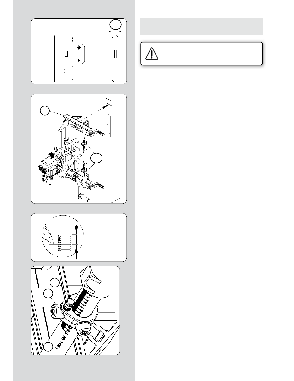
FC116U / Manuale d’istruzioni - 69
12.1. FRESATURA DELL’INCASSO PER LA PIASTRA FRONTALE DELLA SERRATURA PER "Nt" MASSIMO DI 170 mm
Verificare che la fresatrice sia staccata dalla
rete elettrica.
CAMBIARE LA FRESA
• Misurare la larghezza “N1” (Fig. 11) della parte frontale della
serratura e montare sulla macchina una fresa per mortase della
misura corrispondente, seguendo le istruzioni del paragrafo 6
del manuale.
MISURARE, TRACCIARE RIFERIMENTI E POSIZIONARE
FC116U SULLA PORTA
• Prendere le misure tra la scatola della serratura e ciascuna
delle due estremità della parte frontale della serratura “N2” e
“N3” (Fig. 11).
• Se le due misure “N2” e “N3” (Fig. 11) sono uguali: Fissare la
macchina alla porta, allineando lo spigolo superiore della traversa “V” (Fig. 12) con il tratto di riferimento superiore “rs” (Fig. 12).
In questo modo i centri della corsa della macchina, della scatola
e della piastra frontale della serratura sono allineati.
• Se le misure “N2” e “N3” (Fig. 11) non sono uguali, misurare la
differenza tra le stesse “N2”-”N3”=X mm (Fig. 11), tracciare un
nuovo segno di riferimento superiore “rs1” (Fig. 13 e 12), spostato di X mm, verso il lato della misura maggiore tra “N2” e “N3”
e fissare la macchina alla porta, allineando lo spigolo superiore
della traversa “V” (Fig. 12) con il nuovo tratto di riferimento superiore “rsl” (Fig. 12). In questo modo i centri della corsa della
macchina e della piastra frontale della serratura sono allineati.
REGOLARE LA CORSA DELLA FRESATURA
• Misurare la lunghezza della parte frontale “NT” (Fig. 11) della
serratura e fissare i due finecorsa longitudinali “S1” (Fig. 12 e 14)
sulla divisione corrispondente alla misura NT, sulla scala della
colonna di guida “S” (Fig. 14).
• Posizionare e fissare i due finecorsa correttori del diametro
della fresa “S2” (Fig. 14) sul segno corrispondente al diametro
della fresa montata (Fig. 14).
• Regolare la lunghezza della fresatura sulla biella su una misura leggermente superiore alla parte frontale della serratura
“NT” (Fig. 11), come illustrato nel paragrafo 9 (Fig. 6) di questo
manuale.
N1
N2-N3= X mm
N2-N3= X mm
S1
V
"rs"
"rs1"
"rs"
"rs1"
"N3"
"Nt"
"N2"
(Figura 11)
(Figura 12)
(Figura 13)
(Figura 14)
S2
S1
S
Page 70

70 - FC116U / Manuale d’istruzioni
REGOLARE LA PROFONDITÀ DI FRESATURA
• Sollevare la manopola “W” (Figg. 15-18) fino alla posizione
limite superiore, ruotandolo in senso antiorario.
• Verificare che l’asta di bloccaggio “J” (Fig. 15) si trovi in posizione orizzontale (avanzamento in profondità disattivato).
• Allentare la manopola “K” (Fig. 16), spostare la macchina verso
il basso, spingendo leggermente il motore con la mano fino a che
la fresa raggiunge il bordo della porta e mantenerla in questa
posizione fissando la manopola “K” (Fig. 16).
• Posizionare la parte frontale della serratura (Fig. 17) toccando
la parte inferiore del supporto del motore, spostare e fissare il finecorsa di profondità “S3” (Fig. 16 e 17) immobilizzando la parte
frontale della serratura.
• Allentare la manopola “K” (Fig. 15-17) affinché la macchina
salga fino a raggiungere la posizione iniziale.
FRESARE L’INCASSO
• Verificare che l’asta di bloccaggio “J” (Fig. 15) si trovi in posizione orizzontale (avanzamento in profondità disattivato).
• Collegare la macchina alla rete elettrica, mettere in moto il
motore premendo la leva “Y” (Fig. 18) e bloccando la sicura “Z”
(Fig. 18).
• Ruotare la manopola “W” (Fig. 17 e 18) fino a che il supporto
del motore raggiunge il finecorsa di profondità “S3” (Fig. 18).
Quando l’utensile raggiunge la profondità di taglio prevista
per la parte frontale della serratura, azionare la manopola di
avanzamento del carrello “A” (Figg. 15 e 18) lentamente, fino
a raggiungere entrambi i finecorsa “S1” (Fig. 15 e 18), situati
in corrispondenza del termine della corsa del carrello, con un
movimento oscillante.
Se l’incasso da realizzare è superiore a 2 mm, si consiglia di realizzarlo in due o più passate successive, agendo ripetutamente
sulla manopola “W”.
• Riportare la manopola “W” (Fig. 18) e il finecorsa di profondità
“S3” (Fig. 16) in posizione iniziale al termine della fresatura.
(Figura 15)
(Figura 16)
(Figura 17)
(Figura 18)
K
W
S1
A
J
rs
W
K
S3
W
K
S3
S3
W
A
Z
Y
S1
rs1
Page 71
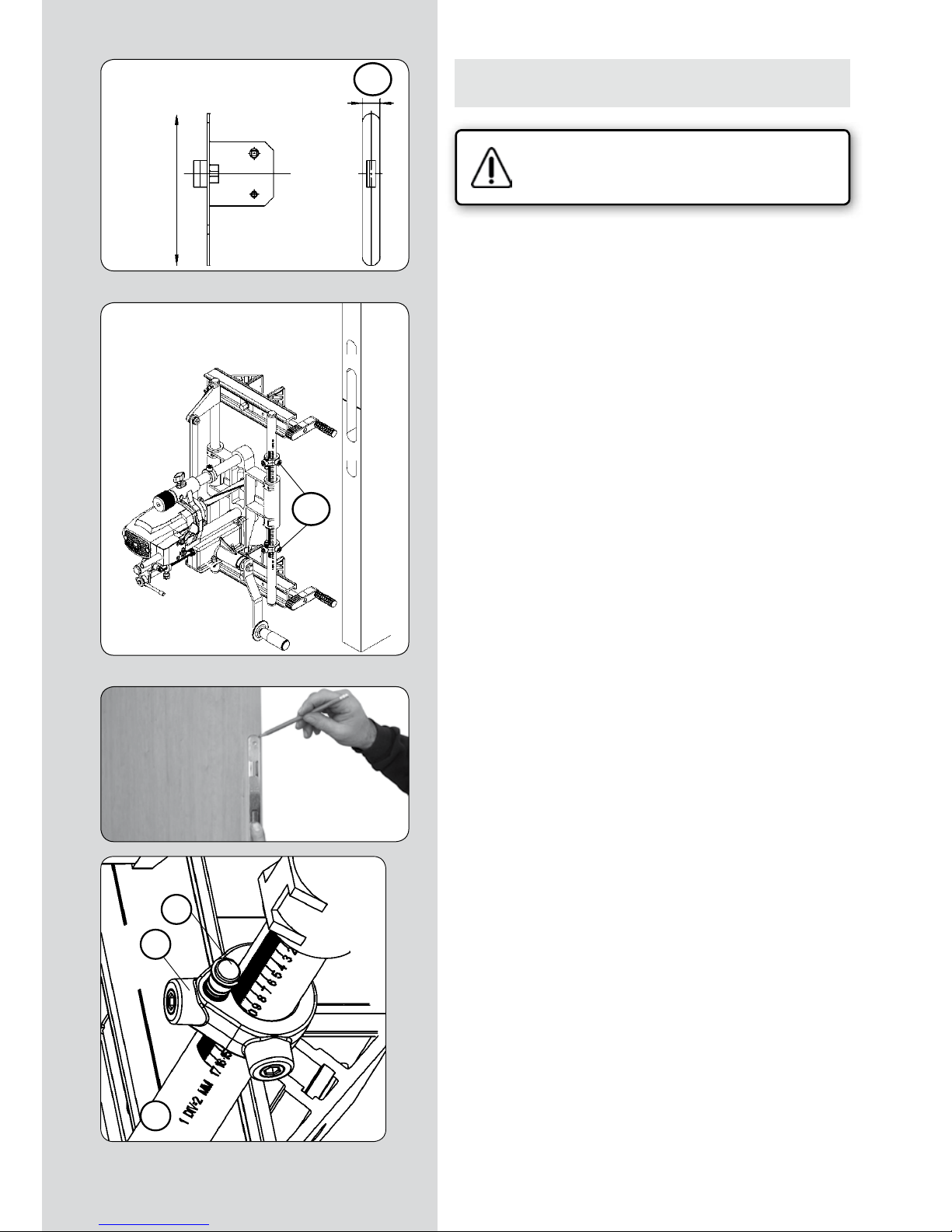
FC116U / Manuale d’istruzioni - 71
12.2. FRESATURA DELL’INCASSO PER LA PIASTRA FRONTALE DELLA SERRATURA PER "Nt" MAGGIORE DI 170 mm
Verificare che la fresatrice sia staccata dalla
rete elettrica.
CAMBIARE LA FRESA
• Misurare la larghezza “N1” (Fig. 11.2) della parte frontale della
serratura e montare sulla macchina una fresa per mortase della
misura corrispondente, seguendo le istruzioni del paragrafo 6
del manuale.
MISURARE E TRACCIARE
• Posizionare la serratura all’interno dell’incasso eseguito per la
scatola e tracciare le due estremità della piastra frontale sul bordo della porta. (Fig. 12.2 e 13.2)
REGOLARE LA CORSA DELLA FRESATURA
• Regolare la lunghezza della fresatura sulla biella per una misura di 170 mm, come spiegato nel paragrafo 9 (Fig. 6) di questo
manuale.
• Fissare i due finecorsa longitudinali “S1” (Fig. 12.2 e 14.2), sulla
divisione corrispondente a 160 mm, sulla scala della colonna di
guida “S” (Fig. 14.2).
REGOLARE LA PROFONDITÀ DI FRESATURA
• Regolare la profondità della fresatura, come spiegato nel paragrafo 12.1 precedente.
(Figura 11.2)
N1
(Figura 12.2)
(Figura 13.2)
(Figura 14.2)
S1
S2
S1
S
"Nt"
Page 72

72 - FC116U / Manuale d’istruzioni
FRESARE L’INCASSO
• Verificare che l’asta di bloccaggio “J” (Fig. 15.2) si trovi in posizione orizzontale (avanzamento in profondità disattivato).
Fresatura della parte superiore dell’incasso:
• Con la mano ruotare l’utensile fino a sistemarlo in posizione
verticale (Fig. 16.2).
• Ruotare la manovella “A” (Fig.15.2) in senso orario (+) fino a
raggiungere il finecorsa superiore “S1” (Fig.15.2) e accertarsi di
mantenerla in tale posizione.
• Staccare la macchina dal bordo della porta e spostarla verticalmente sul bordo stesso fino a che lo spigolo superiore
dell’utensile non coincida con il segno tracciato per la parte superiore del frontale della serratura (Fig.16.2), quindi fissare di
nuovo la macchina sul bordo in questa posizione.
• Collegare la macchina alla rete elettrica, mettere in moto il
motore premendo la leva “Y” (Fig. 18.2) e bloccando la sicura
“Z” (Fig. 18.2).
• Ruotare la manopola “W” (Fig. 18.2) fino a che il supporto del
motore non raggiunga il finecorsa di profondità “S3” (Fig. 18.2).
Quando l’utensile raggiunge la profondità di taglio prevista per
la parte frontale della serratura, azionare la manovella “A” (Fig.
15.2 e 18.2) di avanzamento del carrello verso il basso, procedendo lentamente fino a raggiungere il finecorsa “S1” inferiore
(Fig. 15.2).
Se l’incasso da realizzare è superiore a 2 mm, si consiglia di realizzarlo in due o più passate successive, agendo ripetutamente
sulla manopola “W”.
Fresatura della parte inferiore dell’incasso:
• Con la mano ruotare l’utensile fino a sistemarlo in posizione
verticale (Fig. 16.2).
• Ruotare la manovella “A” (Fig.15.2) in senso antiorario (-), fino
a raggiungere il finecorsa inferiore “S1” (Fig.15.2) e accertarsi di
mantenerla in tale posizione.
• Staccare la macchina dal bordo della porta e spostarla verticalmente sul bordo stesso fino a che lo spigolo inferiore
dell’utensile non coincida con il segno tracciato per la parte
inferiore del frontale della serratura, quindi fissare di nuovo la
macchina sul bordo in questa posizione.
• Collegare la macchina alla rete elettrica, mettere in moto il
motore premendo la leva “Y” (Fig. 18.2) e bloccando la sicura
“Z” (Fig. 18.2).
• Ruotare la manopola “W” (Fig. 18.2) fino a che il supporto del
motore non raggiunga il finecorsa di profondità “S3” (Fig. 18.2).
Quando l’utensile raggiunge la profondità di taglio prevista per
la parte frontale della serratura, azionare la manovella “A” (Fig.
15.2 e 18.2) di avanzamento del carrello verso l’alto, procedendo
lentamente fino a raggiungere il finecorsa “S1” superiore (Fig.
15.2).
Se l’incasso da realizzare è superiore a 2 mm, si consiglia di realizzarlo in due o più passate successive, agendo ripetutamente
sulla manopola “W”.
• Riportare la manopola “W” e il finecorsa di profondità “S3”
(Fig. 18.2) in posizione iniziale al termine della fresatura.
(Figura 15.2)
(Figura 16.2)
(Figura 18.2)
K
W
S1
A
J
S3
W
A
Z
Y
S1
Page 73

FC116U / Manuale d’istruzioni - 73
13. REALIZZAZIONE DEI FORI PER LA MANIGLIA E LA CHIAVE
• Per finire, con l’aiuto della dima UT16I fornita a corredo, è
possibile eseguire i fori necessari al montaggio della serratura,
oltre ai fori per la maniglia, per il nottolino di chiusura, per il
cilindretto della chiave, etc.
MONTAGGIO DELL’UTENSILE DELLA DIMA
UC16I
• Inserire un’asta di altezza smontabile (fornita
a corredo) nei fori “A” e far scorrere l’utensile
fino a posizionare lo “0” di riferimento sul centro “c” della scatola della serratura. (Fig. 19).
• Fissare con la manopola “B” e contemporaneamente livellare il lato interno “C” della
sagoma in lamierino sullo spigolo della porta.
(Fig. 19).
DISPOSIZIONE DELL’UTENSILE E PERFORA-
ZIONE
• Allentare la boccola guida “G” e farla scorrere orizzontalmente
fino a posizionare l’indice “H” in corrispondenza della misura “D”,
stringerlo nuovamente. (Fig. 20).
• Prendendo come riscontro il centro “c” dell’incavo della serratura, fare scorrere l’utensile in senso verticale fino a posizionarlo
sulla misura “E” e “F” desiderata. (Fig. 20)
• Dopo aver determinato la posizione del foro, trapanare con
una punta di 11 mm di diametro.
• Prendendo nuovamente come riscontro il centro”c” dell’incavo
della serratura si potrà determinare l’altro foro necessario per
la serratura.
UTENSILI OPZIONALI PER FORATURA
1640148 Fresa per allargare D.18 c/guida da 11
1640149 Fresa per allargare D.23 c/guida da 11
14. FRESATURA DELL’INCASSO SU VARIE PORTE
• Se desiderate mortasare più porte e sistemare le serrature alla
medesima altezza, si consiglia di adoperare l’asta di regolazione
(Figura 20)
1640148
1640149
(Figura 19)
"c"
A
A
B
"c"
centro caja cerradura "c"
C
G
H
"c"
centro caja cerradura
centro caja cerradura "c"
"c"
Page 74

74 - FC116U / Manuale d’istruzioni
dell’altezza “A1” (Fig. 21) che renderà più facile l’operazione.
Per fare questo, dopo aver determinato l’altezza della serratura
della prima porta, e aver sistemato la macchina nella posizione
di fresatura, montare le quattro aste di regolazione dell’altezza
“A1” (Fig. 21) e inserirle nei fori delle ganasce “X” (Fig. 22), in
modo tale che il disco finecorsa “A2” (Fig. 21) dell’estremità si
fermi sullo spigolo superiore della porta, e fissare l’asta di regolazione dell’altezza “A1” (Figg. 21 e 22) in tale posizione mediante
le manopole “B1” (Fig. 22).
Per la porta seguente non dovrete fare
altro che sistemare la macchina con il disco di finecorsa “A2” (Fig.
21) dell’asta di regolazione dell’altezza “A1” poggiato sullo spigolo
superiore della porta, e fissare le ganasce in tale posizione, segnando (per un uso successivo) il tratto di riferimento superiore “rs”
sulla nuova porta, in modo che tutte le serrature saranno situate
alla stessa altezza.
L’asta di regolazione dell’altezza “A1” (Fig. 21) senza il disco di
finecorsa “A2” (Fig. 21) si può anche adoperare, se si desidera,
come riscontro dell’altezza dal pavimento.
15. FRESATURA DI MORTASE IN POSIZIONE ORIZZONTALE
• Per lavorare con la FC116U in posizione orizzontale, ad esempio
per eseguire mortase in una porta prima di poggiarla sui cardini,
è conveniente staccare l’ammortizzatore “T1” (Fig. 21) in modo
che non eserciti pressione sul carrello “U1”, ostacolandone il movimento.
A tale scopo, allentare il dado “P” (Fig. 23) con la chiave “F” e agire
sulla manopola del perno a vite “R” per spostare l’indicatore di
lunghezza “S” fino al finecorsa “A2”.
Togliere la manopola “S1” (Fig. 21) che sostiene l’ammortizzatore
“T1” per staccare quest’ultimo. Conservare la manopola “S1” in un
luogo sicuro per poterla utilizzare di nuovo.
Infine, regolare la lunghezza di fresatura desiderata - come indicato al punto 9 - prima di lavorare con la macchina, dato che
quest’ultima non deve mai lavorare a finecorsa, oltre la lunghezza
massima.
16. CORREZIONI PER PORTE CON BATTUTA
Per mortasare porte con battuta, occorre correggere il centraggio
della macchina e la profondità della fresatura nel modo seguente:
Verificare che la fresatrice sia staccata dalla
rete elettrica.
• Per centrare la macchina sulla sezione della porta senza battuta, allentare con la chiave “F” (Fig. 22) le viti “Q” che fissano le
ganasce “X” e spostare le piastrine “J1”, verso il lato della battuta,
della metà della larghezza (in mm) di quest’ultima, quindi serrare
nuovamente le viti “Q” in tale posizione.
• Quando si regola la profondità della fresatura, come indicato
nel punto 10, occorrerà sistemare l’anello di finecorsa “A” (Fig. 8)
a un’altezza della scala “U” (Fig. 8) pari alla somma della profondità necessaria per la serratura, più l’altezza della battuta della
porta, dato che la macchina poggerà su tale battuta.
17. KIT ASPIRATORE
• La fresatrice per mortase FC16S dispone di un ugello “D2”
(Figg. 8 e 9) che, montato nell’asta posizionatrice “D1” (Fig. 8),
(Figura 21)
(Figura 22)
(Figura 23)
S1
A2
U1
T1
A1
A2
P
F
R
S
X
A1
B1
X
J
F
Q
Page 75

FC116U / Manuale d’istruzioni - 75
sull’apertura della mortasa da praticare, permette di collegare
l’aspiratore Virutex AS182K, AS282K, AS382L e ASC482U o un
altro aspiratore industriale per estrarre i trucioli creati dalla fresatura.
18. ESTRAZIONE DELL'ALBERO SCANALATO
Per sostituire l’albero scanalato “M” (Fig. 26), smontare dapprima
la fresa “G” (Fig. 25) come indicato nel punto 6.
Sistemare il perno “L” (Fig. 26) nel foro centrale della carcassa, in
modo da bloccare l’albero del motore, ed estrarre l’albero scanalato “M” con la chiave “E”.
19. SOSTITUZIONE DELLE SPAZZOLE
Verificare che la fresatrice sia staccata dalla rete
elettrica prima di eseguire qualsiasi intervento.
• Le spazzole vanno sostituite quando raggiungono una lunghezza minima di 5 mm. Per farlo, smontare la cassa dell’interruttore
“F1” (Fig. 27) togliendo le viti “G1” che la fissano.
Togliere i tappi “H1” che fissano le spazzole “I1” e sostituirle con
nuove spazzole originali Virutex, accertandosi che entrino senza
difficoltà nelle guide. Quando si rimonta la cassa dell’interruttore
“F1”, verificare che i fili interni siano sistemati correttamente.
È consigliabile lasciare la macchina in moto per alcuni minuti
dopo la sostituzione delle spazzole. Approfittate di questa operazione per verificare le condizioni del collettore. Se quest’ultimo
presenta bruciature o deformazioni, è consigliabile farlo riparare
da un servizio tecnico Virutex.
20. LUBRIFICAZIONE E PULIZIA
• Prima di fresare la prima mortasa, lubrificare le colonne di guida della profondità “Gp”, (Fig. 2) e quelle trasversali “Gt”, (Fig. 2),
con uno straccio leggermente imbevuto d’olio, per rendere fluidi
i due movimenti. È importante pulire sempre e accuratamente la
macchina dopo l’uso con un getto d’aria compressa.
Mantenere sempre il filo di alimentazione in perfette condizioni.
21. UTENSILI OPZIONALI
• Frese disponibili per le fresatrici per mortase FC116U:
NUMERO DIAM. EST. ALTEZZA
(Figura 25)
(Figura 24)
(Figura 26)
(Figura 27)
E
D2
D1
F
G
L
E
M
Gt
Gp
F1
G1
H1
I1
I1
H1
Page 76
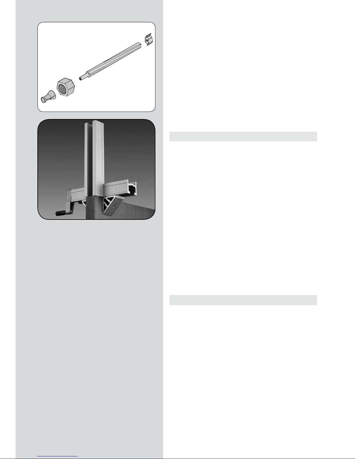
76 - FC116U / Manuale d’istruzioni
1640127 16 mm. 13.5 mm.
1640150 17 “ 13.5 “
1640128 18 “ 13.5 “
1640367 20 “ 13.5 “
1640129 21 “ 13.5 “
1640130 23 “ 13.5 “
1640368 23,5 “ 13.5 “
1640131 25 “ 13.5 “
1640369 29 “ 13.5 “
1640132 30 “ 13.5 “
1640140 Fresa per forature Ø 24
• L’utensile di prolunga UP16I, 1645287 permette di prolungare
il fissaggio della macchina oltre la stessa porta.
22. LIVELLO DI RUMORE
I livelli di rumore e vibrazioni di questo apparato elettrico sono
stati misurati in conformità con la Norma Europea EN 61029-1
e fungono da base di confronto con macchine per applicazioni
simili.
Il livello di vibrazioni indicato è stato determinato per le principali applicazioni dell’apparato e può essere utilizzato come
punto di partenza per la valutazione dell’esposizione al rischio
delle vibrazioni. Ciononostante, il livello di vibrazioni può variare
notevolmente rispetto al valore dichiarato in altre condizioni di
applicazione, con altri strumenti di lavoro o in caso di manutenzione insufficiente dell’apparato elettrico e dei suoi strumenti,
e può aumentare notevolmente come conseguenza del ciclo di
lavoro e del modo d’uso dell’apparato elettrico.
Pertanto è necessario stabilire misure di sicurezza per la protezione dell’utente dall’effetto delle vibrazioni, ad esempio mantenendo l’apparato e gli strumenti di lavoro in perfetto stato e
pianificando i tempi dei cicli lavorativi (ad esempio i tempi di
funzionamento dell’apparato sotto carico e i tempi di funzionamento a vuoto quando l’apparato non viene realmente utilizzato, dato che la riduzione di questi ultimi può ridurre in modo
sostanziale il valore totale dell’esposizione).
23. GARANZIA
Todas las máquinas electroportátiles VIRUTEX, tienen una garantía válida de 12 meses a partir del día de su suministro, quedando
excluidas todas las manipulaciones o daños ocasionados por manejos inadecuados o por desgaste natural de la máquina.
Para cualquier reparación dirigirse al Servicio Oficial de Asistencia VIRUTEX S.A.
VIRUTEX, se reserva el derecho de modificar sus productos sin
previo aviso.
Page 77

FC116U / Manual de instruções - 77
INDICE
Especificações sujeitas a
alteração sem aviso prévio.
MANUAL DE INSTRUÇÕES
1 DADOS TÉCNICOS 78
2 UTILIZAÇÃO 78
3 INSTRUÇÕES DE SEGURANÇA PARA A
UTILIZAÇÃO DA MÁQUINA 79
4 EQUIPAMENTO STANDARD 79
5 MONTAGEM DA MANIVELA AVANÇO
CARRO 79
6 MONTAGEM DAS FERRAMENTAS DE
CORTE 80
7 INTERRUPTOR 80
8 AJUSTAMENTO DA LARGURA DA FRE-
SAGEM 80
9 AJUSTAMENTO DO COMPRIMENTO DA
FRESAGEM 81
10
AJUSTA. DA PROFUNDIDADE DA FRESAGEM 81
11 FRESAGEM DE ENCAIXE NUMA PORTA 82
MEDIR E TRAÇAR REFERÊNCIAS 82
FRESAR O ENCAIXE DA CAIXA 83
12.1
FRESAGEM DO ENCAIXE PARA A PLACA
FRONTAL DA FECHADURA PARA "Nt"
MÁXIMO DE 170 mm 84
SUBSTITUIR A FRESA 84
MEDIR, TRAÇAR REFERÊNCIA E COLOCAR
FC116U NA PORTA 84
REGULAR O PERCURSO DE FRESAGEM 84
REGULAR A PROFUNDIDADE DA FRESAGEM
85
FRESAGEM DO ENCAIXE 85
12.2
FRESAGEM DO ENCAIXE PARA A PLACA
FRONTAL DA FECHADURA PARA "Nt"
SUPERIOR A 170 mm 86
SUBSTITUIR A FRESA 86
MEDIR E TRAÇAR 86
REGULAR O PERCURSO DE FRESAGEM 86
REGULAR A PROFUNDIDADE DA FRESAGEM
86
FRESAGEM DO ENCAIXE 87
13 REALIZAÇÃO DOS FUROS PARA A
MAÇANETA E PARA A CHAVE 88
MONTAGEM DO MOLDE UC16I 88
SITUAÇÃO DO UTENSÍLIO E PERFURAÇÃO 88
FERRAMENTAS OPCIONAIS DE PERFURAÇÃO
88
14 FRESAGEM DO ENCAIXE EM VÁRIAS
PORTAS 89
15 FRESAGEM DE ENCAIXES EM POSIÇÃO
HORIZONTAL 89
16
CORRECÇÕES PARA PORTAS COM SOLAPA
89
17 ACOPLAMENTO DE ASPIRAÇÃO 90
18 EXTRACÇÃO DO EIXO ACANALADO 90
19 SUBSTITUIÇÃO DE ESCOVAS 90
20 LUBRIFICAÇÃO E LIMPEZA 90
21
FERRAMENTAS E ACESSÓRIOS OPCIONAIS
91
22 NIVEL SONORO 91
23 GARANTIA 91
Page 78

78 - FC116U / Manual de instruções
FRESADORA DE ENCAIXES FC116U
IMPORTANTE
Antes de utilizar a máquina leia atentamente este MANUAL DE
INSTRUÇÕES e o FOLHETO DE INSTRUÇÕES GERAIS DE SEGURANÇA anexo. Assegure-se de os ter compreendido antes de
começar a trabalhar com a máquina.
Conserve os dois manuais de instruções para possíveis consultas
posteriores.
1. DADOS TÉCNICOS
Motor universal........................................................................50/60 Hz
Potência........................................................................1.100 W
Velocidade em vazio..................................................23.000 min
-1
Diâmetro máximo da Fresa.......................................................30 mm
Profundidade máxima de fresagem................................0 - 125 mm
Largura máxima de fresagem..........................diâmetro da fresa
Comprimento máx.
de fresagem..................................177mm+diâm. da fresa
Abertura máxima dos tornos...................................................190 mm
Aperto mínimo dos tornos..........................................................13 mm
Deslocação lateral da fresa sobre
a grossura da porta..................................................................± 15 mm
Peso...........................................................................................14 Kg
Nível de pressão acústica contínuo
equivalente ponderado A..............................................................87 dBA
Nível de potência acústica A.....................................................98 dBA
Incerteza.......................................................................................K = 3 dBA
Usar protecção auricular!
Valores totais de vibração...............................................a
h
: <2,5 m/s
2
Incerteza...................................................................................K: 1,5 m/s
2
2. UTILIZAÇÃO
A fresadora portátil encaixes FC116U é uma ferramenta eléctrica
destinada à fresagem de encaixes para montar fechaduras de
portas, ensambláveis à caixa, etc.
Além da caixa para a fechadura, também é possível fresar o encaixe para a placa frontal da fechadura e o encaixe para a placa
do fecho no caixilho. É possível, com a ajuda do utensílio UC16I
incluído com o equipamento, realizar os furos para o cilindro ou
canhão e também para o puxador da porta.
Page 79

FC116U / Manual de instruções - 79
3. INSTRUÇÕES DE SEGURANÇA
PARA A UTILIZAÇÃO DA MÁQUINA
Certifique-se de que a pessoa que vai usar esta
máquina leia cuidadosamente e compreenda este
MANUAL DE INSTRUÇÕES e o FOLHETO DE INSTRUÇÕES GERAIS DE SEGURANÇA anexo, antes
de começar a trabalhar com ela.
• Antes de ligar a máquina, verifique se a tensão de alimentação
de que dispõe corresponde à indicada na placa de características
da máquina.
• Para substituir a fresa ou realizar qualquer outra operação cerca do cabeçal de corte, desligue a máquina da rede de corrente
eléctrica.
• Use óculos de segurança quando trabalhar com a fresadora.
• Não ponha o motor em funcionamento, se se tiver extraído da
armação da máquina.
• Verifique o percurso do cabo de alimentação, a fim de poder
evitar que se possa emaranhar durante a utilização.
• Ponha a fresadora em funcionamento sempre por meio da alavanca do interruptor principal.
• Depois da fresadora se encontrar situada sobre a peça a fresar,
efectue sempre a deslocação da ferramenta utilizando a manivela de avanço do carro. Não empurre nunca com as mãos ou com
ferramentas alheias.
• Certifique-se de que o motor se encontra completamente parado, antes de retirar a fresadora do encaixe realizado.
• Utilize sempre as fresas do diâmetro adequado e correctamente montadas no eixo acanalado.
•
Não utilize jamais fresas incorrectas, defeituosas ou em mau es-
tado. Utilize unicamente fresas e sobressalentes originais VIRUTEX.
4. EQUIPAMENTO STANDARD
No interior da caixa Você encontrará os seguintes elementos:
• Fresadora de encaixes FC116U
• Utensílio de perfuração para o canhão e agulha UT16I
• Chaves de serviço e molde de desenho
• Vareta de altura desmontável em 4 secções e um topo porta.
• Quatro protectores de mordaças para processos delicados de
montagem.
• Fresa de encaixes de diâmetro de 16 mm.
• Manual de instruções e diversa documentação.
5. MONTAGEM DA MANIVELA AVANÇO CARRO
Verifique se a fresadora se encontra desligada da
rede de corrente eléctrica.
• Encaixar a ranhura rectangular da manivela de avanço do carro “A”, colocando-a sobre a superfície do eixo “B”, e colocar a
anilha “C” e o parafuso “D”, tal como se indica na (Fig. 1). Apertar
o parafuso “D” com a chave “F”, para fixar o manípulo de avanço
do carro no seu alojamento.
• IMPORTANTE: NÃO BATER NA SUPERFÍCIE DO MANÍPULO DE
AVANÇO “A”.
Fig. 1
(Figura 1)
Page 80

80 - FC116U / Manual de instruções
6. MONTAGEM DAS FERRAMENTAS DE CORTE
Verifique se a fresadora se encontra desligada
da rede de corrente eléctrica.
• A fresadora de encaixes fornece-se com uma fresa do diâmetro
de 16 mm, montada na extremidade do eixo acanalado.
A fim de substituir a fresa, bloqueie o eixo acanalado pelos seus
planos, com a chave “E” (Fig. 2), desenrosque a fresa “G” com a
chave “F” e substitua-a por outra do diâmetro desejado.
7. INTERRUPTOR
• A caixa do interruptor (Fig. 3), é provida de uma alavanca “Y”
para o arranque da máquina e de um seguro de encravamento
lateral “Z”. A fim de poder efectuar o arranque, há que accionar
o seguro de encravamento “Z” e, sem o soltar, premir a alavanca
“Y”, mantendo-se de esta maneira a máquina em movimento.
Ao premir a alavanca “Y” tendo a máquina em movimento, o
seguro “Z” desencrava-se automaticamente e a máquina pára.
O seguro de encravamento do interruptor “Z” impede a entrada
em movimento acidental da máquina.
8. AJUSTAMENTO DA LARGURA DA FRESAGEM
• Meça o ponto mais largo “N” da caixa da fechadura, incluindo
qualquer protuberância que tiver (Fig. 4). NÃO INCLUA a face
embelezadora exterior da fechadura.
Verifique se a fresadora se encontra desligada
da rede de corrente eléctrica.
• Coloque uma fresa de encaixes da medida feita, ou ligeiramente maior, seguindo as instruções do capítulo 6.
(Figura 4)
(Figura 2)
(Figura 3)
Y
E
G
F
Z
N
Page 81

FC116U / Manual de instruções - 81
9. AJUSTAMENTO DO COMPRIMENTO DA FRESAGEM
• Meça o ponto mais largo “H” da caixa de fechadura, incluindo
qualquer protuberância que tiver (Fig. 5). NÃO INCLUA a face
embelezadora exterior da fechadura.
Verifique se a fresadora se encontra desligada da
rede de corrente eléctrica.
• A fim de ajustar a máquina ao comprimento de fresagem “H”
desejado, afrouxe a porca “P” (Fig. 6) com a chave “F” e accione a
manete fuso “R” até que o indicador de comprimento “S” alcance
a medida desejada “H” e aperte a porca “P” nesta posição.
Tenha a certeza de apertar a porca "P" (Fig.
6); do contrário, pode-se produzir a rotura do
mecanismo de ajustamento do comprimento de
fresagem.
A centragem da fresa sobre a grossura da porta, ou da peça a
encaixar, é automática se as plaquinhas “J” (Fig. 7) estiverem na
posição de “0” nas duas guias torno “V” (Fig. 7).
10. AJUSTAMENTO DA PROFUNDIDADE DA FRESAGEM
• Meça a profundidade “T” (Fig. 5) da caixa da fechadura, incluindo qualquer proteburância que tiver no seu fundo, incluindo a grossura da face embelezadora exterior e uns mm mais
como folga.
Verifique se a fresadora se encontra desligada da
rede de corrente eléctrica.
• A profundidade de fresagem controla-se por meio da régua
graduada “U” (Fig. 8), a qual se encontra marcada em divisões
de 1 mm. Afrouxe a manete “W” e coloque o anel “A”, de modo
que a sua face inferior coincida com a profundidade desejada, e
aperte a manete “W” nessa posição.
(Figura 6)
(Figura 8)
(Figura 5)
T
H
F
R
P
S
W
A
U
(Figura 7)
J
V
V
V
A
W
Page 82

82 - FC116U / Manual de instruções
11. FRESAGEM DE ENCAIXE NUMA PORTA
• Coloque a porta em posição e fixe-a firmemente, para que não
se mexa. Se a porta já se encontrar montada no friso, coloque
cunhas debaixo dela, a fim de que não se mexa.
MEDIR E TRAÇAR REFERÊNCIAS
• Colocar a fechadura contra a porta de modo a que o furo para
a maçaneta ou puxador da porta se situe à altura desejada “H0”
relativamente ao solo (Fig. 9), e marcar uma linha “0” (Fig. 9) na
face e no canto da porta.
• Medir a distância “H2” (Fig. 9), do centro do puxador até ao
centro da caixa da fechadura.
• Marque o centro “c” da caixa da fechadura sobre o canto
da porta utilizando o molde “Pt” (Fig. 9) que acompanha o
equipamento.
O molde possui uma série de ranhuras situadas a uma distância
de 5 mm entre si, pelo que deve colocar o molde sobre o canto da
porta, fazendo coincidir o traço “0” (Fig. 9), com a ranhura que
corresponde à medida “H2” (Fig. 9) que desenhou anteriormente, (20 mm na Fig. 9), e marque o traço “c” (Fig. 9) no rebordo
inferior do molde.
• Marcar a referência superior “rs” (Fig. 9), que servirá como
referência para a montagem da máquina sobre a porta.
Para isso, situe a extremidade inferior do molde de desenho “Pt”
(Fig. 9) sobre o traço “c” (Fig. 9), e marque o traço “rs” (Fig. 9) na
extremidade superior do molde.
(Figura 9)
Pt
"c"
"H2"
"rs"
"H2"
"0"
"rs"
"rs"
"c"
"H0"
"0"
"c"
"c"
"c"
"0"
"H2"
Page 83
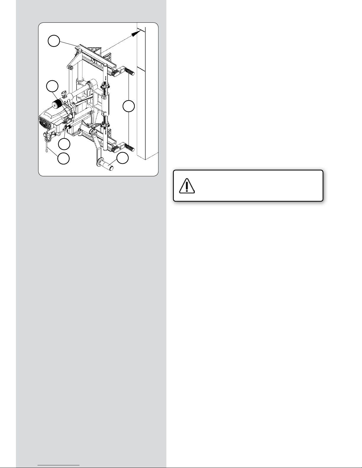
FC116U / Manual de instruções - 83
FRESAR O ENCAIXE DA CAIXA
• Colocar a máquina sobre a porta, alinhando a aresta superior
do travessão “V” (Fig. 10), com o traço de referência superior “rs”
(Fig. 10) e fixar firmemente as mordaças usando as alavancas
“K” (Fig. 10).
• Verifique se a manivela de avanço “A” (Fig. 10) pode girar
livremente em todo o seu percurso.
• Gire a vareta blocagem “J” (Fig. 10) para a posição vertical, a
fim de engrenar o mecanismo de avanço da profundidade de
fresagem.
• Ligar a máquina à rede de alimentação eléctrica, e accionar o
motor usando a alavanca “Y” (Fig. 10) e bloquear a segurança
carregando em “Z” (Fig. 10).
• Gire repetidamente a manivela de avanço “A” (Fig. 10), com o
qual obterá um avanço sincronizado da ferramenta, longitudinal
e em profundidade, até ao final do percurso fixado no capítulo
10.
• Detenha a máquina ao accionar a alavanca “Y” do interruptor
(Fig. 10).
Desligue a fresadora da rede de corrente eléctrica.
• Girar a vareta de bloqueio “J” (Fig. 10) até atingir a posição
horizontal, libertando o mecanismo de avanço da ferramenta e
fazendo o motor retroceder até ao final do percurso.
(Figura 10)
V
Y
K
J
Z
A
"rs"
"c"
Page 84

84 - FC116U / Manual de instruções
12.1. FRESAGEM DO ENCAIXE PARA A PLACA FRONTAL DA
FECHADURA PARA "Nt" MÁXIMO DE 170 mm
Verifique se a fresadora se encontra desligada
da rede de corrente eléctrica.
SUBSTITUIR A FRESA
• Meça a largura “N1” (Fig. 11) da parte frontal da fechadura
e monte na máquina uma fresa com a medida correspondente,
seguindo as instruções da secção 6 do manual.
MEDIR, TRAÇAR REFERÊNCIA E COLOCAR FC116U NA PORTA
• Registar as medidas entre a caixa da fechadura e cada uma das
extremidades da parte frontal da fechadura “N2” e “N3” (Fig. 11).
• Se as duas medidas “N2” e “N3” (Fig. 11) forem iguais: Apertar
a máquina de encontro à porta, alinhando a aresta superior do
travessão”V” (Fig. 12), com o traço de referência superior “rs”
(Fig. 12), alinhando assim os centros do percurso da máquina, da
caixa da fechadura e da placa frontal da fechadura.
• Se as medidas “N2” e “N3” (Fig. 11) não forem iguais, registe a
diferença entre ambas “N2”-”N3”=X mm (Fig. 11) e desenhe uma
nova marca de referência superior “rs1” (Fig. 13 e 12), com uma
deslocação de X mm para o lado da medida maior entre “N2” e
“N3”, e seguidamente aperte a máquina de encontro à porta alinhando a aresta superior do travessão “V” (Fig. 12), com o novo
traço de referência superior “rs1” (Fig. 12), alinhando assim o
centro do percurso da máquina com o centro da placa frontal
da fechadura.
REGULAR O PERCURSO DE FRESAGEM
• Medir o comprimento da parte frontal “NT” (Fig. 11) da fechadura, e fixar os dois topos longitudinais “S1” (Fig. 12 e 14), sobre
a divisão correspondente à medida NT na escala da coluna de
guia “S” (Fig. 14).
• Posicionar e fixar os dois topos correctores do diâmetro da
fresa “S2” (Fig. 14), sobre a marca correspondente ao diâmetro
da fresa montada (Fig. 14).
• Ajustar o comprimento da fresagem na biela a uma medida um
pouco maior do que a da parte frontal da fechadura “NT” (Fig.
11), tal como se demonstrou na secção 9 (Fig. 6) deste manual
N1
N2-N3= X mm
N2-N3= X mm
S1
V
"rs"
"rs1"
"rs"
"rs1"
"N3"
"Nt"
"N2"
(Figura 11)
(Figura 12)
(Figura 13)
(Figura 14)
S2
S1
S
Page 85

FC116U / Manual de instruções - 85
REGULAR A PROFUNDIDADE DA FRESAGEM
• Girar a alavanca “W” (Figs. 15-18) até à sua posição limite
superior, girando-a no sentido anti-horário.
• Verificar que a vareta de bloqueio “J” (Fig. 15) se encontra na
posição horizontal (avanço de profundidade desligado).
• Afrouxar a alavanca “K” (Fig. 16); deslocar a máquina para
baixo, empurrando-a suavemente com a mão sobre o motor, até
que a fresa toque o canto da porta, e mantê-la nesta posição
fixando a alavanca “K” (Fig. 16).
• Colocar a parte frontal da fechadura (Fig. 17), tocando a parte
inferior do suporte do motor; deslocar e fixar o topo de profundidade “S3” (Fig. 16 e 17), fixando a parte frontal da fechadura.
• Afrouxar a alavanca “K” (Fig. 15-17), para que a máquina possa
subir até à sua posição inicial.
FRESAGEM DO ENCAIXE
• Verificar que a vareta de bloqueio “J” (Fig. 15) se encontra na
posição horizontal (avanço de profundidade desconectado).
• Ligue a máquina à rede de alimentação eléctrica e ligue o motor accionando a alavanca “Y” (Fig. 18) e bloqueie o dispositivo
de segurança carregando em “Z” (Fig. 18).
• Girar a alavanca”W” (Fig. 17 e 18) até que o suporte do motor
toque o topo de profundidade “S3” (Fig.18). Quando a ferramenta alcançar a profundidade de corte prevista para a parte frontal
da fechadura, accionar a manivela de avanço do carro “A” (Fig.
15 e 18) com suavidade até alcançar cada um dos dois topos “S1”
(Fig. 15 e 18), situados em cada final do percurso do carro, num
movimento de vai-vém.
Se o encaixe a realizar for superior a 2 mm, é aconselhável
executá-lo em duas ou mais passagens sucessivas, accionando
repetidamente a alavanca “W”.
• Colocar a alavanca “W” (Fig. 18) e o topo de profundidade “S3”
(Fig. 16) na sua posição inicial ao terminar a fresagem.
(Figura 15)
(Figura 16)
(Figura 17)
(Figura 18)
K
W
S1
A
J
rs
W
K
S3
W
K
S3
S3
W
A
Z
Y
S1
rs1
Page 86

86 - FC116U / Manual de instruções
12.2. FRESAGEM DO ENCAIXE PARA A PLACA FRONTAL DA
FECHADURA PARA "Nt" SUPERIOR A 170 mm
Verifique se a fresadora se encontra desligada
da rede de corrente eléctrica.
SUBSTITUIR A FRESA
• Meça a largura “N1” (Fig. 11.2) da parte frontal da fechadura
e monte na máquina uma fresa com a medida correspondente,
seguindo as instruções da secção 6 do manual.
MEDIR E TRAÇAR
• Colocar a fechadura no interior do encaixe realizado para a
caixa, e traçar os dois extremos da placa frontal sobre o canto da
porta. (Fig. 12.2 e 13.2)
REGULAR O PERCURSO DE FRESAGEM
• Ajustar o comprimento de fresagem na biela a 170 mm, tal
como se explica na secção 9 (Fig. 6) deste manual
• Fixar os dois topos longitudinais “S1” (Fig. 12.2 e 14.2), sobre
a divisão correspondente a 160 mm, na escala da coluna de guia
“S” (Fig. 14.2).
REGULAR A PROFUNDIDADE DA FRESAGEM
• Regular a profundidade de fresagem, tal como se explica na
secção 12.1 anterior
N1
S1
"Nt"
(Figura 11.2)
(Figura 12.2)
(Figura 13.2)
(Figura 14.2)
S2
S1
S
Page 87
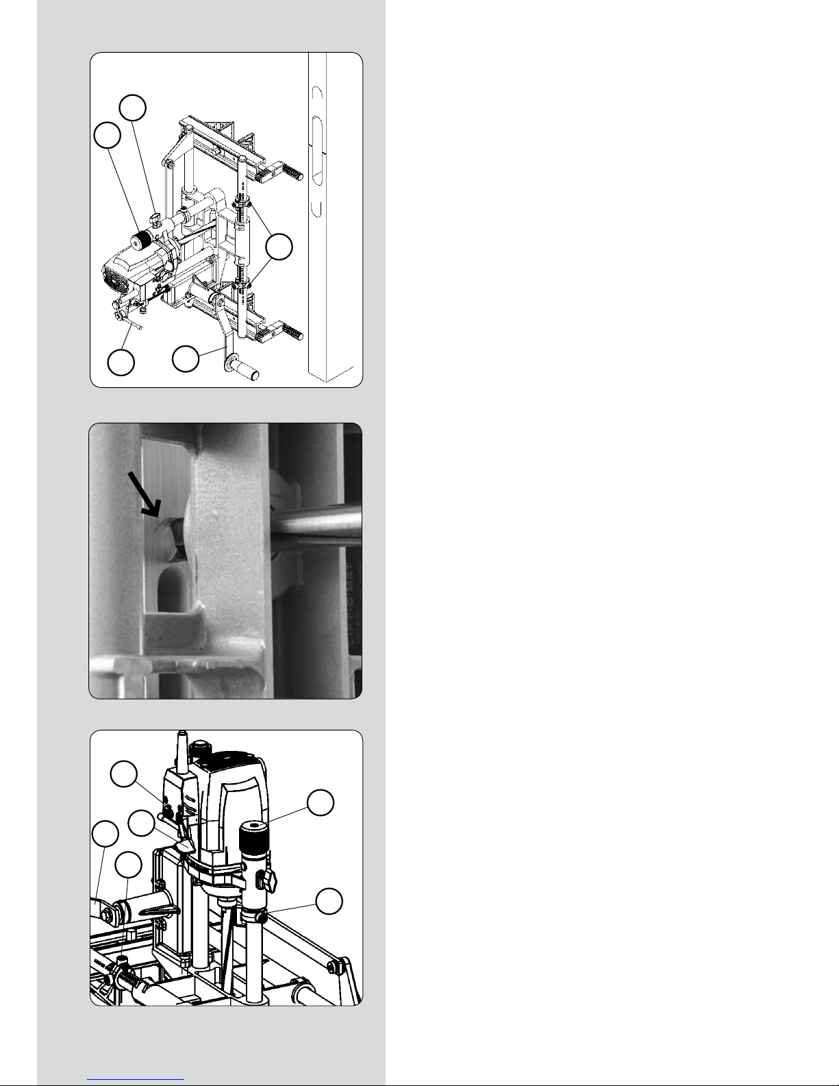
FC116U / Manual de instruções - 87
FRESAGEM DO ENCAIXE
• Verificar que a vareta de bloqueio “J” (Fig. 15.2) se encontra
na posição horizontal (avanço de profundidade desconectado).
Fresar a parte superior do encaixe:
• Girar a ferramenta com a mão até a situar na posição vertical
(Fig. 16.2).
• Girar a manivela “A” (Fig.15.2) no sentido horário (+), até alcançar o topo superior “S1” (Fig.15.2) e mantê-la nessa posição.
• Soltar a máquina do canto da porta e deslocá-la verticalmente
sobre o mesmo, até que a aresta superior da ferramenta coincida
com o traço superior da parte frontal da fechadura (Fig.16.2) e
fixar novamente a máquina sobre o canto nesta posição.
• Ligue a máquina à rede de alimentação eléctrica e ligue o motor accionando a alavanca “Y” (Fig. 18) e bloqueie o dispositivo
de segurança carregando em “Z” (Fig. 18.2).
• Girar el pomo “W” (Figs. 18.2) hasta que el soporte del motor
toque el tope de profundidad “S3” (Fig.18.2). Al alcanzar la herramienta la profundidad de corte prevista para el frontal de la
cerradura, accionar la manivela “A” (Figs. 15.2 y 18.2) de avance
del carro hacia abajo con suavidad, hasta alcanzar el tope “S1”
inferior (Fig. 15.2).
Se o encaixe a realizar for superior a 2 mm, é aconselhável
executá-lo em duas ou mais passagens sucessivas, accionando
repetidamente a alavanca “W”.
Fresar a parte inferior do encaixe:
• Girar a ferramenta com a mão até a situar na posição vertical
(Fig. 16.2).
• Girar a manivela “A” (Fig.15.2) no sentido anti-horário (–), até
alcançar o topo inferior “S1” (Fig.15.2) e mantê-la nessa posição.
• Soltar a máquina do canto da porta e deslocá-la verticalmente
sobre o mesmo, até que a aresta inferior da ferramenta coincida
com o traço inferior da parte frontal da fechadura, e fixar novamente a máquina sobre o canto nesta posição.
• Ligue a máquina à rede de alimentação eléctrica e ligue o motor accionando a alavanca “Y” (Fig. 18) e bloqueie o dispositivo
de segurança carregando em “Z” (Fig. 18.2).
• Girar a alavanca “W” (Fig. 18.2) até o suporte do motor tocar
no topo de profundidade “S3” (Fig.18.2). Quando a ferramenta
alcançar a profundidade de corte prevista para a parte frontal
da fechadura, accionar a manivela de avanço do carro “A” (Fig.
15.2 e 18.2) para cima com suavidade, até alcançar o topo “S1”
superior (Fig. 15.2).
Se o encaixe a realizar for superior a 2 mm, é aconselhável
executá-lo em duas ou mais passagens sucessivas, accionando
repetidamente a alavanca “W”.
• Colocar a alavanca “W” e o topo de profundidade “S3” (Fig.
18.2) na sua posição inicial ao terminar a fresagem.
(Figura 15.2)
(Figura 16.2)
(Figura 18.2)
K
W
S1
A
J
S3
W
A
Z
Y
S1
Page 88
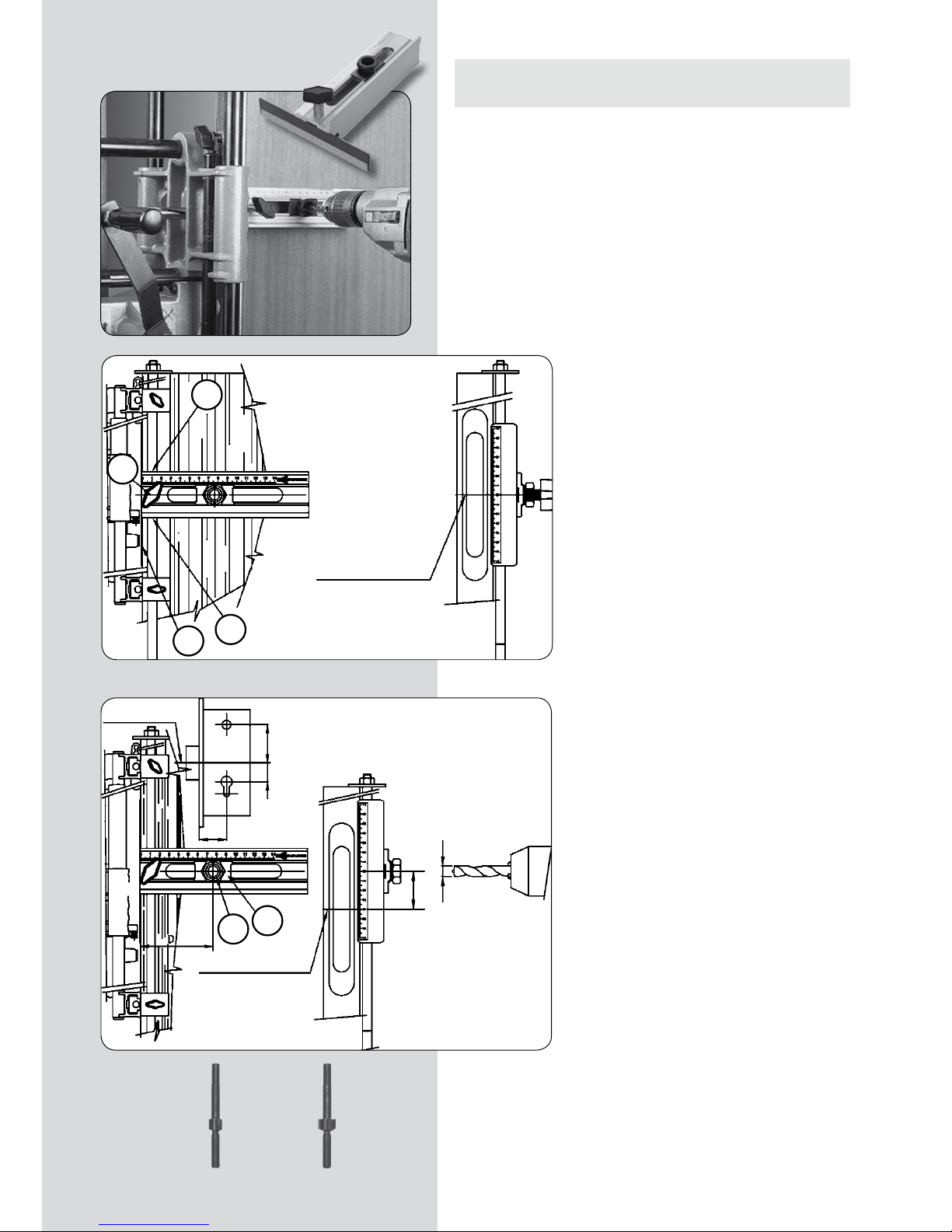
88 - FC116U / Manual de instruções
13. REALIZAÇÃO DOS FUROS PARA A MAÇANETA E PARA
A CHAVE
• Por último, com a ajuda do molde UT16I fornecido com a máquina, podem realizar os furos necessários para a montagem da
fechadura, como os orifícios de passagem da maçaneta, do fecho
manual, do canhão da chave, etc.
MONTAGEM DO MOLDE UC16I
• Introduzir uma das varetas de altura desmontável incluídas com o equipamento no
interior dos orifícios “A”, e deslizar o utensílio
até colocar o “0” de referência sobre o centro
“c” da caixa da fechadura. (Fig. 19).
• Fixar com a manete “B” e, ao mesmo tempo, nivelar a face interna “C” da chapa de referência no canto da porta. (Fig. 19).
SITUAÇÃO DO UTENSÍLIO E PERFURAÇÃO
• Afrouxar o casquilho guia “G” e deslizá-lo
no sentido horizontal, situando o índice “H”
na medida “D”, e apertá-lo novamente. (Fig.
20).
• Tomando como referência o centro “c” da
caixa da fechadura, deslizar o utensílio no
sentido vertical para o situar na medida “E”
ou “F” desejada. (Fig. 20)
• Depois de situada a posição do orifício, proceder-se-á a efectuar a perfuração com uma
broca de 11 mm de diâmetro.
• Tendo a referência de novo no centro “c”
da caixa da fechadura, poder-se-á situar o
seguinte orifício que a fechadura necessitar.
FERRAMENTAS OPCIONAIS DE PERFURAÇÃO
1640148 Fresa de alargamento D.18 c/guia de 11
1640149 Fresa de alargamento D.23 c/guia de 11
(Figura 20)
(Figura 19)
1640148
1640149
"c"
A
A
B
"c"
centro caja cerradura "c"
C
G
H
"c"
centro caja cerradura
centro caja cerradura "c"
"c"
Page 89

FC116U / Manual de instruções - 89
14. FRESAGEM DO ENCAIXE EM VÁRIAS PORTAS
• Se desejar fazer encaixes em várias portas e colocar as fechaduras a uma mesma altura, aconselhamos-lhe que empregue a
vareta de alturas “A1” (Fig. 21), o que lhe facilitará a operação.
Para isso, depois de ter determinado a altura da fechadura na
primeira porta e de ter situado a máquina na posição de fresas,
monte as quatro varetas de altura “A1” (Fig. 21) e introduza-as nos
orifícios dos tornos “X” (Fig. 22), de modo que o Disco de topo “A2”
(Fig. 21) da sua extremidade estabeleça topo no canto superior da
porta, e fixe a vareta de altura “A1” (Figs. 21 e 22) nesta posição
por meio das manetes “B1” (Fig. 22). Para a porta seguinte, basta
colocar a máquina como disco de topo “A2” (Fig. 21), da vareta
de altura “A1”, assente sobre o canto superior da porta, e fixar as
mordaças nesta posição, marcando para uso posterior o traço de
referência superior “rs” na nova porta para que todas as fechaduras se situem à mesma altura.
A vareta de alturas “A1” (Fig. 21) sem o disco topo “A2” (Fig. 21)
pode também ser empregue, se o desejar, como referência da
altura em relação ao chão.
15. FRESAGEM DE ENCAIXES EM POSIÇÃO HORIZONTAL
• Para trabalhar com a FC116U em posição horizontal, como por
exemplo para a realização de encaixes em portas antes de pendurá-las, é conveniente desligar o amortecedor “T1” (Fig. 21), a fim
de deixar livre da sua pressão, o movimento do Carro “U1”.
Para isso, afrouxar a porca “P” (Fig. 23) com a chave “F” e, accionando a manete Fuso “R”, deslocar o Indicador de comprimento
“S” até ao Topo “A2” de final de percurso.
Retirar a manete “S1” (Fig. 21), que agarra o amortecedor “T1”,
para que este fique desligado. Guardar a manete “S1” num lugar
seguro, para uma próxima utilização.
Finalmente, ajustar o comprimento de fresagem desejado, de
acordo com o modo indicado no capítulo 9, antes de trabalhar
com a máquina, visto que esta não deve trabalhar nunca no final
de percurso, acima do comprimento máximo.
16. CORRECÇÕES PARA PORTAS COM SOLAPA
Para o encaixe de portas com solapa, deverá corrigir a centragem da
máquina e a profundidade de fresagem, do seguinte modo:
Verifique se a fresadora se encontra desligada
da rede de corrente eléctrica.
• A fim de centrar a máquina sobre a secção da porta sem solapa,
afrouxe a chave “F” (Fig. 22) e os parafusos “Q” que bloqueiam
os tornos “X”, e desloque as placas “J” para o lado da solapa, à
metade da largura desta em mm, e fixe de novo os parafusos “Q”
nesta posição.
• Ao ajustar a profundidade de fresagem, tal e como se explica
no capítulo 10, deverá colocar o anel de topo “A” (Fig. 8) a uma
altura da escala “U” (Fig. 8) que seja a soma da profundidade
necessária para a fechadura mais a altura da solapa da porta,
visto que a máquina se apoiará nesta solapa.
(Figura 21)
(Figura 22)
(Figura 23)
S1
A2
U1
T1
A1
A2
P
F
R
S
X
A1
B1
X
J
F
Q
Page 90

90 - FC116U / Manual de instruções
17. ACOPLAMENTO DE ASPIRAÇÃO
• A máquina de encaixes FC116U dispõe de uma boquilha “D2”
(Fig. 24) que, depois de montada na vareta de posição “D1” (Fig.
24), sobre a abertura da caixa a realizar, permite a ligação do
aspiradores Virutex AS182K, AS282K, AS382L e ASC482U ou de
outro aspirador industrial, para a extracção das aparas da fresagem.
18. EXTRACÇÃO DO EIXO ACANALADO
Para trocar o eixo acanalado “M” (Fig. 26) desmonte primeiro a
fresa “G” (Fig. 25), conforme explicado no capítulo 6.
Coloque o passador “L” (Fig. 26) no orifício central da carcaça,
até bloquear o eixo do motor e extraia o eixo acanalado “M”
com a chave “E”.
19. SUBSTITUIÇÃO DE ESCOVAS
Certifique-se de que a máquina esteja desligada
da rede de corrente eléctrica, antes de realizar
qualquer manipulação.
• As escovas devem ser substituídas quanto tiverem um comprimento mínimo de 5 mm. Para isso, desmonte a caixa do interruptor “F1” (Fig. 27), retirando os parafusos “G1” que a agarram.
Tire os tampões “H1” que agarram as escovas “I1” e substitua-as
por outras originais VIRUTEX, comprovando que deslizem suavemente no interior das guias. Ao montar de novo a caixa interruptor “F1”, certifique-se de que os cabos fiquem bem situados
no seu interior.
É aconselhável deixar a máquina em funcionamento em vazio
durante alguns minutos, depois de uma substituição de escovas.
Aproveite a substituição de escovas para verificar o estado do
colector. Se este apresentasse queimaduras ou saliências, torna-se aconselhável levá-lo a um Serviço Técnico VIRUTEX para
repará-lo.
20. LUBRIFICAÇÃO E LIMPEZA
• Antes de fresar o primeiro encaixe, lubrifique as colunas de
guia da profundidade “Gp” (Fig. 25) e as transversais “Gt” (Fig.
25) com um pano ligeiramente impregnado em óleo, para suavizar os dois movimentos. É importante limpar sempre a máquina
depois da sua utilização, empregando um jacto de ar seco.
Mantenha sempre o cabo de alimentação em perfeitas condições
de utilização.
(Figura 25)
(Figura 24)
(Figura 26)
(Figura 27)
E
D2
D1
F
G
L
E
M
Gt
Gp
F1
G1
H1
I1
I1
H1
Page 91
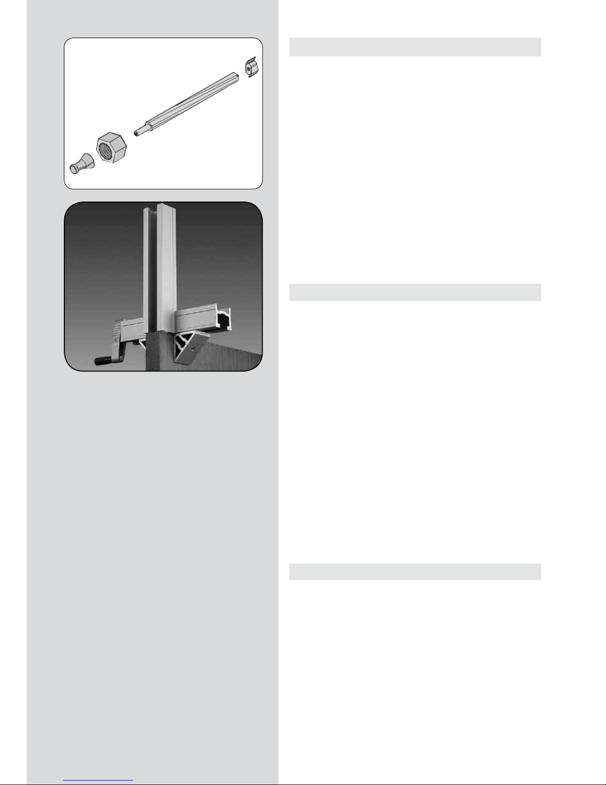
FC116U / Manual de instruções - 91
21. FERRAMENTAS E ACESSÓRIOS OPCIONAIS
• Fresas para a fresadora de encaixes FC116U disponíveis:
NÚMERO DIÂM. EXT. ALTURA
1640127 16 mm. 13.5 mm.
1640150 17 “ 13.5 “
1640128 18 “ 13.5 “
1640367 20 “ 13.5 “
1640129 21 “ 13.5 “
1640130 23 “ 13.5 “
1640368 23,5 “ 13.5 “
1640131 25 “ 13.5 “
1640369 29 “ 13.5 “
1640132 30 “ 13.5 “
1640140 Fresa de taladrar Ø 24
• O utensílio de extensão UP16I, 1645287 permite prolongar a
fixação da máquina para além da própria porta.
22. NIVEL SONORO
Os níveis de ruído e vibrações desta ferramenta eléctrica foram
medidos de acordo com a Norma Europeia EN 61029-1 e servem
como base de comparação com uma máquina de aplicação semelhante.
O nível de vibrações indicado foi determinado para as principais
aplicações da ferramenta e pode ser utilizado como valor de partida para a avaliação da exposição ao risco das vibrações. Contudo, o nível de vibrações pode alcançar valores muito diferentes
do valor indicado noutras condições de aplicação, com outros
dispositivos de trabalho ou com uma manutenção deficiente da
ferramenta eléctrica e respectivos dispositivos, podendo resultar
num valor muito mais elevado devido ao seu ciclo de trabalho e
modo de utilização.
Por conseguinte, é necessário estabelecer medidas de segurança
para protecção do utilizador contra o efeito das vibrações, tais
como a manutenção da ferramenta, conservação dos respectivos
dispositivos em perfeito estado e organização dos períodos de
trabalho (tais como os períodos de trabalho com a ferramenta
em carga e períodos de trabalho com a ferramenta em vazio e
sem ser realmente utilizada, uma vez que a redução da carga
pode diminuir de forma substancial o valor total da exposição).
23. GARANTIA
Todas as máquinas VIRUTEX possuem uma garantia válida por
12 meses contados a partir do dia de fornecimento, ficando dela
excluídas todas as manipulações ou danos ocasionados por utilizações não adequadas, ou pelo desgaste natural da máquina.
Para qualquer reparação, há que se dirigir ao Serviço Oficial de
Assistência Técnica VIRUTEX.
A VIRUTEX reserva para si o direito de poder modificar os seus
produtos, sem a necessidade de aviso prévio.
Page 92

92 - FC116U /
Инструкция по эксплуатации
ОГЛАВЛЕНИЕ
1
ТЕХНИЧЕСКИЕ ХАРАКТЕРИСТИКИ
93
2
ОБЛАСТЬ ПРИМЕНЕНИЯ
93
3
ИНСТРУКЦИЯ ПО ТЕХНИКЕ
БЕЗОПАСНОСТИ
94
4
СТАНДАРТНЫЙ КОМПЛЕКТ ПОСТАВКИ
94
5
УСТАНОВКА ПРИВОДНОЙ РУКОЯТКИ
94
6
УСТАНОВКА ФРЕЗЫ
95
7
ВКЛЮЧЕНИЕ
95
8
УСТАНОВКА ШИРИНЫ ФРЕЗЕРОВАНИЯ
95
9
УСТАНОВКА ДЛИНЫ ФРЕЗЕРОВАНИЯ
96
10
УСТАНОВКА ГЛУБИНЫ ФРЕЗЕРОВАНИЯ
96
11
ФРЕЗЕРОВАНИЕ ПОСАДОЧНОГО МЕСТА ЗАМКА
97
ИЗМЕРЕНИЕ И НАНЕСЕНИЕ РАЗМЕТКИ
97
ФРЕЗЕРОВАНИЕ ПОСАДОЧНОГО МЕСТА
98
12.1
ФРЕЗЕРОВАНИЕ ПОСАДОЧНОГО МЕСТА
ПРИ ДЛИНЕ ПЕРЕДНЕЙ ПЛАНКИ "Nt" до
170 мм
99
ЗАМЕНА ФРЕЗЫ
99
ИЗМЕРЕНИЯ, РАЗМЕТКА И УСТАНОВКА
FC116U НА ДВЕРИ
99
НАСТРОЙКА ДЛИНЫ ФРЕЗЕРОВАНИЯ
99
НАСТРОЙКА ГЛУБИНЫ ФРЕЗЕРОВАНИЯ
100
ФРЕЗЕРОВАНИЕ ПОСАДОЧНОГО МЕСТА
100
ИНСТРУКЦИЯ ПО ЭКСПЛУАТАЦИИ
12.2
ФРЕЗЕРОВАНИЕ ПОСАДОЧНОГО МЕСТА
ПРИ ДЛИНЕ ПЕРЕДНЕЙ ПЛАНКИ "Nt"
БОЛЕЕ 170 мм
101
ЗАМЕНА ФРЕЗЫ
101
ИЗМЕРЕНИЯ И РАЗМЕТКА
101
НАСТРОЙКА ДЛИНЫ ФРЕЗЕРОВАНИЯ
101
НАСТРОЙКА ГЛУБИНЫ ФРЕЗЕРОВАНИЯ
101
ФРЕЗЕРОВАНИЕ ПОСАДОЧНОГО МЕСТА
102
13
СВЕРЛЕНИЕ ОТВЕРСТИЙ ПОД РУЧКУ И
ЗАПОРНЫЙ ЦИЛИНДР
103
ПОДГОТОВКА К УСТАНОВКЕ ШАБЛОНА UТ16I
103
УСТАНОВКА И СВЕРЛЕНИЕ
103
ДОПОЛНИТЕЛЬНЫЙ ИНСТРУМЕНТ ДЛЯ СВЕРЛЕНИЯ
103
14
ВРЕЗКА ЗАМКА ДЛЯ СЕРИИ ДВЕРЕЙ
104
15
ФРЕЗЕРОВАНИЕ В ГОРИЗОНТАЛЬНОЙ
ПЛОСКОСТИ
104
16
НАСТРОЙКА ДЛЯ ДВЕРЕЙ С ПРИТВОРОМ
104
17
ПРИСПОСОБЛЕНИЕ ДЛЯ ПЫЛЕУДАЛЕНИЯ
105
18
ЗАМЕНА НЕСУЩЕЙ ОСИ ФРЕЗЫ
105
19
ЗАМЕНА УГОЛЬНЫХ ЩЕТОК
105
20
ЧИСТКА И СМАЗКА
105
21
ДОПОЛНИТЕЛЬНЫЙ ИНСТРУМЕНТ И
ОСНАСТКА
106
22
УРОВЕНЬ ШУМА И ВИБРАЦИИ
106
23
ГАРАНТИЙНЫЕ ОБЯЗАТЕЛЬСТВА
106
Page 93

FC116U / Инструкция по эксплуатации - 93
FC116U ФРЕЗЕР ДЛЯ ВРЕЗКИ ЗАМКОВ
ВАЖНО!
Внимательно изучите данное руководство по эксплуатации
и храните его в легкодоступном месте рядом с данным
устройством.
Внимательно прочитайте инструкцию по технике
безопасности и руководство по эксплуатации перед началом
работы с данным устройством. Сохраните комплект
сопроводительной документации для обращения к нему при
необходимости.
1. ТЕХНИЧЕСКИЕ ХАРАКТЕРИСТИКИ
Универсальный мотор.................................................50/60 Гц
Мощность......................................................................1,100 Вт
Частота вращения.............................................23,000 об/мин
Макс. диаметр фрезы.....................................................30 мм
Макс. глубина фрезерования..................................0-125 мм
Макс. ширина фрезерования..........................диаметр фрезы
Макс. длина фрезерования.........177 мм + диаметр фрезы
Макс. открытие фиксатора........................................190 мм
Макс. смещение фиксаторов.....................................13 мм
Диапазон регулирования по ширине двери.............+/- 15 мм
Вес.....................................................................................14 кг
Эквивалентный непрерывный
уровень звукового давления A...................................87 дБ(А)
Уровень акустического давления..........................98 дБ(А)
Погрешность.............................................................K = 3 дБ(А)
Используйте средства защиты органов слуха!
Уровень вибрации.................................................a
h
: <2,5 м/с
2
Погрешность..................................................K: 1,5 м/с
2
2. ОБЛАСТЬ ПРИМЕНЕНИЯ
Фрезер FC116U – переносной электрический инструмент для
фрезерования пазов для установки врезных дверных замков
и посадочных мест под переднюю пластину.
При помощи приспособления для сверления UТ16I,
входящего в стандартный комплект поставки, осуществляется
выборка отверстий под ручку и запорный цилиндр.
Page 94

94 - FC116U / Инструкция по эксплуатации
3. ИНСТРУКЦИЯ ПО ТЕХНИКЕ БЕЗОПАСНОСТИ
Убедитесь, что лицо, обслуживающее
данный инструмент, перед началом работы
внимательно изучил ИНСТРУКЦИЮ ПО
ЭКСПЛУАТАЦИИ И ИНСТРУКЦИЮ ПО ТЕХНИКЕ
БЕЗОПАСНОСТИ и понял изложенное в них.
• Перед подключением инструмента к сети убедитесь, что
напряжение источника питания соответствует техническим
характеристикам, указанным на шильдике инструмента.
• Перед заменой режущего инструмента или выполнением
любой другой операции в непосредственной близости от
режущего инструмента отключите инструмент от источника
питания.
• При работе с инструментом используйте средства защиты
органов зрения.
• Не запускайте демонтированный двигатель.
• Проверьте кабель электропитания, убедитесь в его
целостности и том, что он не перекручен.
• Для пуска инструмента всегда используйте основной
выключатель.
• Для перемещения фрезера в процессе фрезерования
пользуйтесь только приводной рукояткой. Никогда не
перемещайте инструмент вручную или сторонним инструментом.
• Убедитесь в полной остановке двигателя перед
извлечением фрезы из готового паза.
• Используйте только оригинальные фрезы, надежно
закрепленные на несущей оси.
• Никогда не используйте поврежденные или затупившиеся
фрезы. Используйте только оригинальные запчасти и
комплектующие VIRUTEX.
4. СТАНДАРТНЫЙ КОМПЛЕКТ ПОСТАВКИ
Стандартная комплектация включает:
• Фрезер FC116U
• Приспособление для сверления UT16I
• Сервисные ключи и шаблон
• Штанга ограничительная 4-х секционная и стопор.
• Накладки защитные на лапки фиксаторов, 4 шт.
• Фреза, ø16 мм.
• Инструкция по эксплуатации и прочая документация.
5. УСТАНОВКА ПРИВОДНОЙ РУКОЯТКИ
Убедитесь в том, что инструмент
отключен от внешнего источника питания.
• Совместите прямоугольный паз рукоятки “A” с посадочным
местом оси “B” и установите рукоятку. Установите шайбу “C”
и винт “D”, (см. рис. 1). Для закрепления рукоятки затяните
винт “D” при помощи ключа “F”.
• НЕ ПРИЛАГАЙТЕ УДАРНОЙ НАГРУЗКИ ДЛЯ УСТАНОВКИ
РУКОЯТКИ “A” В ЕЕ ПОСАДОЧНОЕ МЕСТО.
Fig. 1
(рисунок 1)
Page 95

FC116U / Инструкция по эксплуатации - 95
6. УСТАНОВКА РЕЖУЩЕГО ИНСТРУМЕНТА
Убедитесь в том, что инструмент
отключен от внешнего источника
питания.
• Фрезер стандартно комплектуется фрезой ø16 мм,
установленной на держатель фрезы. Для замены фрезы
зафиксируйте несущую ось при помощи ключа “E” (рис.
2), открутите фрезу “G” при помощи ключа “F” и замените
фрезой требуемого диаметра.
7. ВКЛЮЧЕНИЕ
• Пусковой блок (рис. 3) оснащен флажковым рычагом “Y”
для пуска инструмента и дополнительным фиксатором
“Z”. Для пуска инструмента подвиньте фиксатор “Z” и, не
отпуская его, толкните вперед рычаг “Y”.
При нажатии на рычаг “Y” во время работы инструмента
фиксатор “Z” освобождается автоматически и двигатель
останавливается. Фиксатор “Z” предотвращает случайный
запуск инструмента.
8. ШИРИНА ФРЕЗЕРОВАНИЯ
• Измерьте ширину корпуса замка “N” в его самом широком
месте (рис. 4). При определении наибольшего размера по
ширине НЕ ИЗМЕРЯЙТЕ переднюю планку замка.
Убедитесь в том, что инструмент
отключен от внешнего источника
питания.
• Установите фрезу требуемого диаметра (в соответствии
с измерениями) или чуть большего размера, согласно
инструкциям в разделе 6.
(рисунок 4)
(рисунок 2)
(рисунок 3)
Y
E
G
F
Z
N
Page 96

96 - FC116U / Инструкция по эксплуатации
9. УСТАНОВКА ДЛИНЫ ФРЕЗЕРОВАНИЯ
• Измерьте корпус замка в его самом длинном месте “H”, включая
любую его выпуклость (рис. 5). При определении наибольшего
размера по длине НЕ ИЗМЕРЯЙТЕ переднюю планку замка.
Убедитесь в том, что инструмент
отключен от внешнего источника питания.
• Для настройки инструмента на заданную длину фрезерования
“H” отпустите гайку “P” (рис. 6) при помощи ключа “F” и вращайте
регулировочную рукоятку “R” до тех пор, пока индикатор длины
“S” не дойдет до требуемого значения “H”. Зафиксируйте
систему в выбранном положении при помощи гайки “P”.
Убедитесь в том, что гайка "P" затянута
(рис. 6); если нет, это может повредить
механизм установки длины фрезерования.
Центровка фрезы относительно толщины дверного полотна
происходит автоматически, если индикатор на пластине
“J” (рис. 7) в положении “0”, относительно направляющих
механизма фиксации “V” (рис. 7).
10. УСТАНОВКА ГЛУБИНЫ ФРЕЗЕРОВАНИЯ
• Измерьте глубину замка “T” (рис. 5), включая любую его
выпуклость, толщину передней планки замка, а также
необходимый технологический припуск.
Убедитесь в том, что инструмент
отключен от внешнего источника питания.
• Глубина фрезерования устанавливается по шкале “U”
(рис. 8), с ценой деления 1 мм. Для установки глубины
фрезерования ослабьте фиксатор “W” ограничителя “A” и
переместите кольцо таким образом, чтобы его нижний срез
соответствовал требуемой глубине фрезерования. Затяните
фиксатор “W”.
(рисунок 6)
(рисунок 8)
(рисунок 5)
T
H
F
R
P
S
W
A
U
(рисунок 7)
J
V
V
V
A
W
Page 97

FC116U / Инструкция по эксплуатации - 97
11. ФРЕЗЕРОВАНИЕ ПОСАДОЧНОГО МЕСТА ЗАМКА
• Установите дверное полотно вертикально и надежно его
зафиксируйте. Если дверное полотно уже установлено
на петли установите под нее клинья чтобы исключить ее
движение.
ИЗМЕРЕНИЕ И НАНЕСЕНИЕ РАЗМЕТКИ
• Приложите замок к дверному полотну таким образом,
чтобы линия ручки находилась на желаемом расстоянии от
уровня пола “H0” (рис. 9) и нанесите отметку “0” (рис. 9) на
торце и лицевой поверхности дверного полотна.
• Измерьте расстояние “H2” (рис. 9) между центральной
линией замка и центром отверстия под ручку.
• Отметьте центр “c” замка на торцевой поверхности
дверного полотна при помощи шаблона “Pt” (рис. 9),
который входит в комплект поставки.
Шаблон имеет ряды отверстий с шагом 5 мм. Наложите
шаблон на торец дверного полотна таким образом,
чтобы отметка “0” (рис. 9) была видна в отверстии,
соответствующем ранее измеренному значению “H2” (рис.
9), в данном случае 20 мм. Нанесите отметку “c” (рис. 9) по
нижней грани шаблона.
• Нанесите верхнюю линию разметки “rs” (рис. 9),
которая соответствует месту крепления инструмента на
дверном полотне.
Чтобы это сделать, наложите шаблон “Pt” (рис. 9) нижней
гранью в соответствии с отметкой “c” (рис. 9) и отметьте точку
“rs” (рис. 9) по верхнему срезу шаблона.
(рисунок 9)
Pt
"c"
"H2"
"rs"
"H2"
"0"
"rs"
"rs"
"c"
"H0"
"0"
"c"
"c"
"c"
"0"
"H2"
Page 98
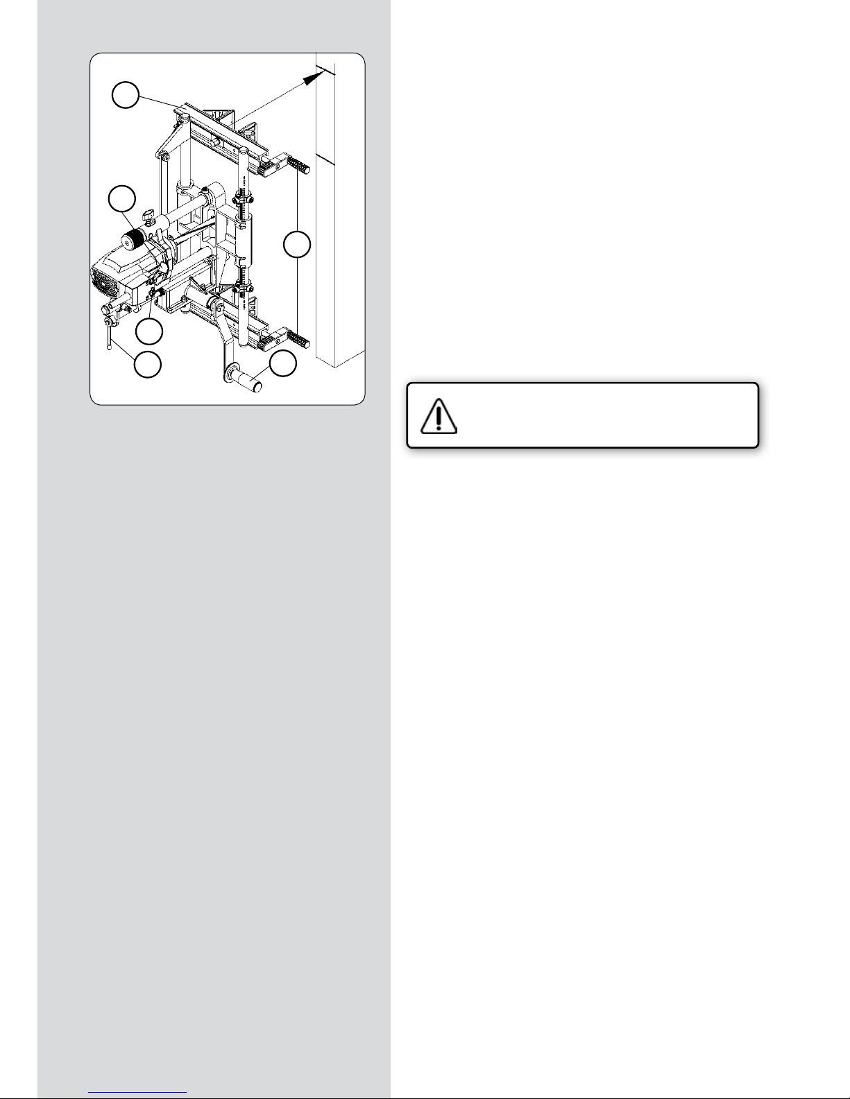
98 - FC116U / Инструкция по эксплуатации
ФРЕЗЕРОВАНИЕ
• Удерживая инструмент напротив торца двери, совместите
верхний край поперечины “V” (рис. 10) с отметкой “rs” (рис.
10) и надежно зафиксируйте инструмент при помощи
рукояток “K” (рис. 10).
• Убедитесь в том, что ничего не мешает вращению
приводной рукоятки “A” (рис. 10).
• Введите в зацепление червячный механизм подачи
по глубине, повернув ручку “J” (рис. 10) в вертикальное
положение.
• Подключите инструмент к электрической сети, при помощи
флажкового рычага “Y” (рис. 10) и фиксатора “Z” (рис. 10)
включите двигатель.
• Вращая рукоятку “A” (рис. 10) отфрезеруйте посадочное
место под тело замка. Углубление фрезы при каждом
проходе будет происходить автоматически до достижения
заданной глубины фрезерования (см. п. 10 ).
• Для остановки двигателя нажмите на рычаг “Y” (рис. 10).
Отключите инструмент от электросети.
• Поверните ручку “J” (рис. 10) в горизонтальное положение,
при этом инструмент вернется в исходное положение.
(рисунок 10)
V
Y
K
J
Z
A
"rs"
"c"
Page 99

FC116U / Инструкция по эксплуатации - 99
12.1 ФРЕЗЕРОВАНИЕ ПОСАДОЧНОГО МЕСТА
ПРИ ДЛИНЕ ПЕРЕДНЕЙ ПЛАНКИ "Nt" до 170 мм
Убедитесь в том, что инструмент
отключен от внешнего источника
питания.
ЗАМЕНА ФРЕЗЫ
• Измерьте ширину “N1” (рис. 11) передней планки замка и
установите фрезу требуемого размера, следуя инструкциям,
изложенным в п. 6 данного руководства.
ИЗМЕРЕНИЯ, РАЗМЕТКА И УСТАНОВКА FC116U НА
ДВЕРИ
• Измерьте расстояние между корпусом замка и каждым из
двух краев передней планки, что даст Вам соответственно
размеры “N2” и “N3” (рис. 11).
• Если размеры “N2” и “N3” (рис. 11) одинаковы: Удерживая
инструмент напротив двери, совместите край поперечины
“V” (рис. 12) с отметкой “rs” (рис. 12). Таким образом, центр
паза под тело замка и посадочного места передней планки
совпадут.
• Если размеры “N2” и “N3” (рис. 11) не совпадают,
определите разность между полученными значениями, “N2””N3”=X мм (рис.11) и нанесите новую отметку “rs1” (рис. 13 и
12), при этом смещение на величину X мм осуществляется в
сторону большего из “N2” и “N3” значения. Затем, удерживая
инструмент напротив двери, совместите край поперечины
“V” (рис. 12) с новой отметкой “rs1” (рис. 12), таким образом
центр паза совпадет с центром передней пластины замка.
НАСТРОЙКА ДЛИНЫ ФРЕЗЕРОВАНИЯ
• Измерьте длину передней планки замка “NT” (рис. 11)
и установите стопоры “S1” (рис. 12 и 14) в положение,
соответствующее размеру NT, используя шкалу на
направляющей “S” (рис. 14).
• Установите и зафиксируйте положение стержня стопора
“S2” (рис. 14) в соответствии с диаметром установленной
фрезы (рис. 14).
• Настройте длину фрезерования в соответствии с размером
“NT” (рис. 11) или чуть более, как описано в разделе 9 (рис.
6) данной инструкции.
(рисунок 11)
N1
N2-N3= X mm
(рисунок 12)
(рисунок 13)
(рисунок 14)
N2-N3= X mm
S1
V
S2
S1
S
"rs"
"rs1"
"rs"
"rs1"
"N3"
"Nt"
"N2"
Page 100
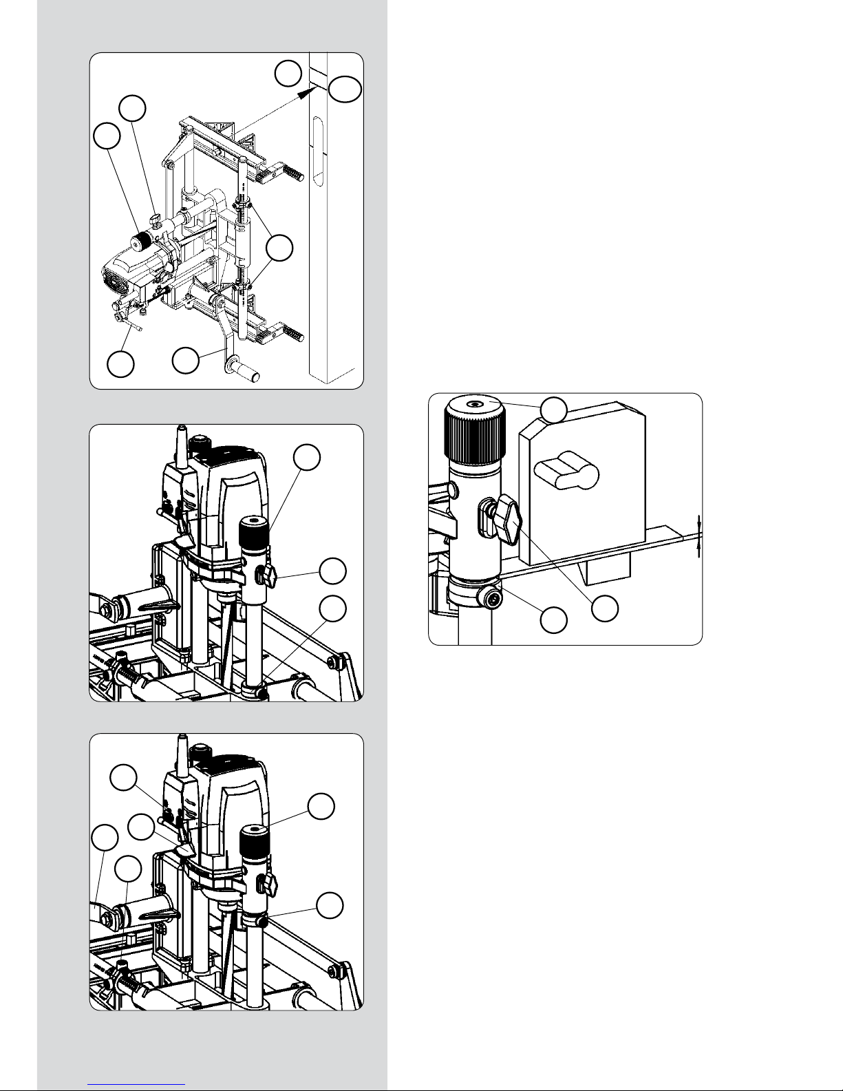
100 - FC116U / Инструкция по эксплуатации
НАСТРОЙКА ГЛУБИНЫ ФРЕЗЕРОВАНИЯ
• Поднимите головку “W” (рис. 15-18) в ее крайнее верхнее
положение, вращая ее против часовой стрелки.
• Убедитесь в том, что рычаг “J” (рис. 15) находится в
горизонтальном положении (механизм подачи по глубине не
работает).
• Ослабьте фиксатор “K” (рис. 16). Подайте привод вниз,
нажав на него руками, до момента касания фрезой
поверхности дверного полотна. Закрепите привод в данном
положении, затянув фиксатор “K” (рис. 16).
• Приложите переднюю планку замка (рис. 17) таким
образом, чтобы она касалась нижней части основания
двигателя, и прижмите ее ограничителем “S3” (рис. 16 и 17).
Зафиксируйте ограничитель “S3” в данном положении.
• Ослабьте фиксатор “K” (рис. 15-17), при этом фрезер
вернется в исходное положение.
ФРЕЗЕРОВАНИЕ ПОСАДОЧНОГО МЕСТА
• Убедитесь в том, что рычаг “J” (рис. 15) находится в
горизонтальном положении (механизм подачи по глубине не
работает).
• Подключите инструмент к электрической сети, при помощи
флажкового рычага “Y” (рис. 18) и фиксатора “Z” (рис. 18)
включите двигатель.
• Поворачивайте рукоятку “W” (рис. 17 и 18) до тех пор, пока
основание двигателя не коснется ограничителя “S3” (рис. 18).
При достижении заданной глубины фрезерования, вращая
рукоятку “A” (рис. 15 и 18) отфрезеруйте паз между двумя
стопорами “S1” (рис. 15 и 18), расположенными на концах
траектории движения. Если глубина фрезерования более 2
мм рекомендуется выполнять фрезерование в два и более
прохода, регулируя глубину погружения рукояткой “W”.
• По завершению фрезерования верните рукоятку “W” (рис.
18) и ограничитель “S3” (рис. 16) в исходные положения.
(рисунок 15)
(рисунок 16)
(рисунок 17)
(рисунок 18)
K
W
S1
A
J
rs
W
K
S3
W
K
S3
S3
W
A
Z
Y
S1
rs1
 Loading...