

Page 1
MANUAL DE INSTRUCCIONES
OPERATING INSTRUCTIONS
MODE D’ EMPLOI
GEBRAUCHSANWEISUNG
MANUALE D’ISTRUZIONI
MANUAL DE INSTRUÇÕES
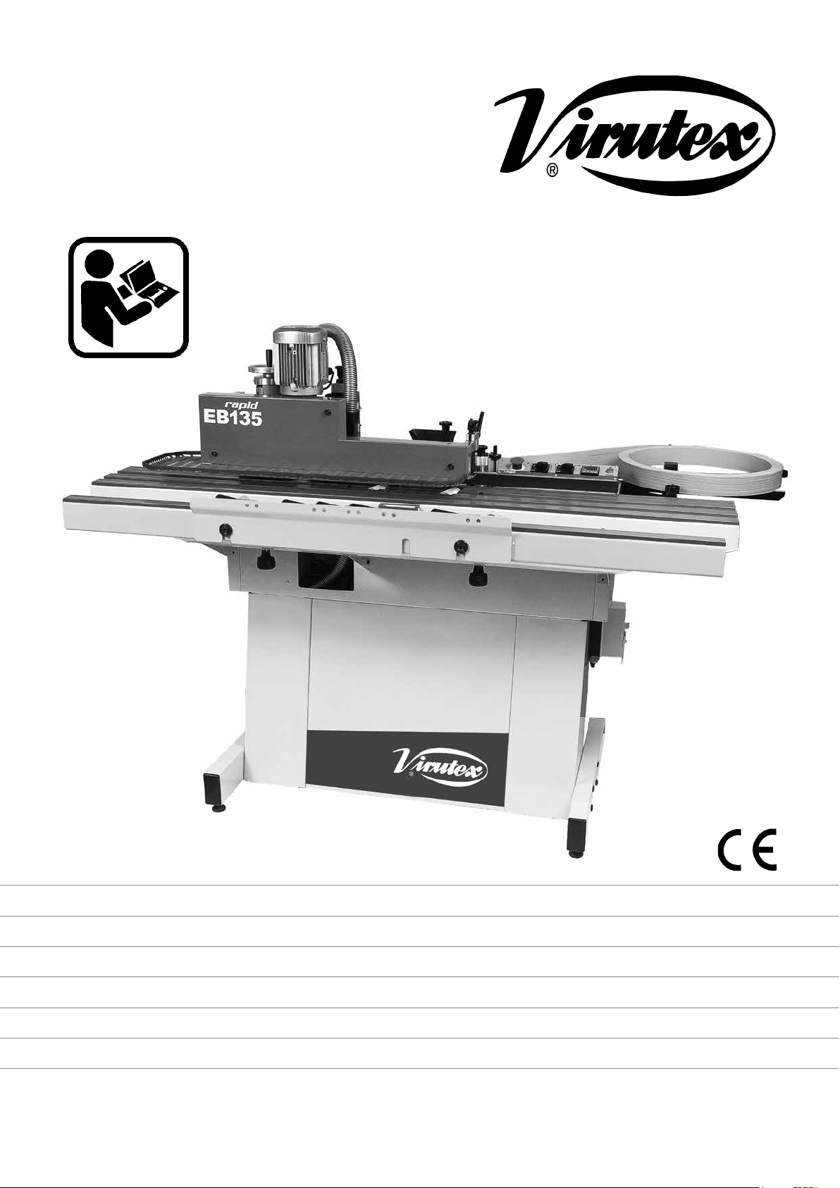
EB135 Rapid
Aplacadora de cantos
Edgebander
Plaqueuse de chants
Kantenleimmaschinen
Bordatrice
Orladora
Page 2
MANUAL DE INSTRUCCIONES
OPERATING INSTRUCTIONS
MODE D'EMPLOI
GEBRAUCHSANWEISUNG
MANUALE D'ISTRUZIONI
MANUAL DE INSTRUÇÕES
página/page
seite/pagina
ESPAÑOL Aplacadora de cantos EB135 Rapid
ENGLISH EB135 Rapid Edgebander
FRANÇAIS Plaqueuse de chants EB135 Rapid
DEUTSCH Kantenleimmaschinen EB135 Rapid
ITALIANO Bordatrice EB135 Rapid
PORTUGUÉS Orladora EB135 Rapid
ESPAÑOL
APLACADORA DE CANTOS EB135 Rapid
(Figuras en página 41)
1.1. INSTRUCCIONES DE SEGURIDAD PARA
EL MANEJO DE LA APLACADORA
Lea atentamente el FOLLETO DE INSTRUCCIONES
GENERALES DE SEGURIDAD, que se adjunta con la
documentación de la máquina.
• Asegúrese antes de conectar la máquina, que la tensión de alimentación,
se corresponda con la indicada en la chapa de características.
• Mantenga siempre las manos alejadas de las áreas de corte y las
zonas de temperatura.
• No utilice nunca fresas y cuchillas incorrectas, defectuosas o en
mal estado.
• No anular ningún mecanismo de seguridad de la máquina.
• Para cualquier manipulación de mantenimiento en la máquina,
desconectarla de la red eléctrica y bloquear la tapa de seguridad K de
la caja interruptor L (Fig. 7).
• Conservar el cable de alimentación en buenas condiciones.
• No utilice la máquina sin conectarla a un sistema de aspiración.
• Use siempre recambios originales VIRUTEX.
2
8
14
21
27
34
sucia obtendrá aplacados de mala calidad.
• Asegúrese de tener suficiente cola completamente fundida en el
depósito, para acabar el trabajo.
• Cuando se disponga a encolar los cantos, utilice la cola especial
Virutex ref. 2599266 desarrollada para este uso.
• También puede usar una de las siguientes colas homologadas por
Virutex:
- Rayt tipo MA-6244
- Kleiberit 743.7
- Kleiberit VP9296/57
- Jowat 280.3
Especial para tableros atamborados
- Quiadsa TM-1800
- Quiadsa TM-1805
Especial para cantos 3D y cristal
- Dorus KS224/2
• Virutex sólo garantiza el buen funcionamiento de la aplacadora
si se emplea alguna de las colas recomendadas.
1.3. CONSUMO DE COLA Y CANTO APROPIADO (Fig. 37)
• Observe en la tabla adjunta, el consumo de cola según la altura del
canto, e independientemente de su espesor. Por ejemplo: Un canto de
23 mm de altura consume 2,5 gramos por metro de promedio.
• También la tabla sirve para saber hasta que tipo de canto se puede
utilizar según su altura y espesor. Por ejemplo: el grueso máximo que
puede utilizar es 3 mm x 25 mm de altura, o el máximo de altura que
puede utilizar es 54 mm x 0,4 mm.
1.2. RECOMENDACIONES A TENER EN CUENTA ANTES DE
EMPEZAR A TRABAJAR CON LA EB135
• El canto del tablero a aplacar debe estar a 90° con su superficie y
libre de polvo.
• Para obtener un buen acabado, en el aplacado de cantos delgados en
tableros de partículas, la superficie del canto del tablero debe ser buena.
• Las piezas y los cantos que vaya a encolar deben estar a temperatura
ambiente no inferior a 18°C (64ºF).
• Efectúe siempre una presión suficiente contra el canto para obtener
un buen aplacado.
• Compruebe que la cantidad de cola que recibe el canto es la apropiada, haciendo una muestra.
• El depósito de cola debe mantenerse tapado y seco.
• El adhesivo desprende vapores al ser mantenido a la temperatura de
trabajo. Asegure su eliminación, por ejemplo mediante una adecuada
ventilación del lugar de trabajo.
• Mantenga la máquina limpia de polvo o virutas. Con una máquina
2
2. CARACTERISTICAS TÉCNICAS
Voltaje......................................................................................................220-240 V
Potencia absorbida.....................................................................................3450 W
Grueso mínimo de tablero..........................................................................13 mm
Grueso máximo de tablero, con canto de esp. 1 mm.........................50 mm
Grueso máximo de tablero, con canto de esp. 2 mm........................50 mm
Grueso máximo de tablero, con canto de esp. 3 mm.......................22 mm
Capacidad perfilador máximo........................................................................3 mm
Capacidad máxima de restestado.................................................................2 mm
Ancho mínimo del tablero..........................................................................102 mm
Longitud mínima del tablero....................................................................180 mm
Regulación electrónica de la temperatura......................................110º-200º C
Velocidad de trabajo....................................................................................4 m/min
Peso.......................................................................................................150 Kg
Nivel de Presión acústica Ponderado A...............................................<80 dBA
Incertidumbre de la medición............................................................K = 3 dBA
Page 3
¡Usar protectores auditivos!
3. EQUIPO ESTANDAR
Al abrir la caja de embalaje, encontrará en su interior los elementos
siguientes:
1. Aplacadora de cantos EB135 Rapid
2. Cjto. soporte desplazable
3. Cjto. prensores
4. Caja conteniendo:
• Dosificador
• Cargador de canto
• Juego de herramientas de servicio
• Galga perfilador
• Rodillo para canto 3D/cristal
5. Documentación
Herramientas opcionales
Fresa M.D. radio 3 y chaflán de 10º: superior 8540172, inferior 8540173
(Fig. 2).
Fresa M.D. radio 2 y chaflán de 10º: superior 8540183, inferior 8540184
(Fig. 2). Incluida de origen.
Fresa M.D. chaflán 45º: superior 8540185, inferior 8540186 (Fig. 2).
4. DIMENSIONES APLACADORA
El espacio ocupado por la aplacadora, esta representado en la (Fig. 1).
5. ENSAMBLAJES PREVIOS
MONTAJE DEL CARGADOR
• Desenroscar los tornillos I de su alojamiento (Fig. 3).
• Colocar el cargador R1 y fijarlo con los tornillos y arandelas I.
• Comprobar que los rodillos N del cargador cinta, giren libremente.
bobina de mínima tensión y sistema de bloqueo de seguridad, para la
manipulación o reparación de la máquina. Indicador luminoso de color
rojo M1 (Fig. 7), encendido en presencia de corriente eléctrica. En caso
de sobrecarga eléctrica, se desconecta automáticamente, dejando sin
tensión todos los elementos.
Panel de control A3 (Fig. 6): Indicador luminoso verde M (Fig. 6),
encendido cuando la máquina se encuentra en marcha.
Control de temperatura Q (Fig. 6), que permite la regulación de la
temperatura de la cola.
Paro de emergencia P (Fig. 6), pulsador que al ser accionado, interrumpe
inmediatamente todas las funciones de la máquina. Para su desbloqueo,
debe girarse el pulsador P en el sentido de la flecha. La máquina no
podrá ponerse de nuevo en marcha, con el interruptor L (Fig. 5 y 7) si
el pulsador de emergencia P (Fig. 6) no ha sido desbloqueado.
Mando CM1 (Fig. 6) de ajuste del sobrante de canto en los extremos
delantero y trasero.
En posición 1: Retestado delantero y trasero. Ambos extremos sin
sobrante.
En posición 2: Retestado delantero, con sobrante detrás.
En posición 3: Retestado trasero, con sobrante delante.
En posición 4: Con sobrante en los dos extremos del tablero.
Mando CM2 (Fig. 6):
En posición 0: Alimentador y control de temperatura desconectados.
En posición 1: Pone en marcha el alimentador y el control de temperatura.
En posición 2: Pone en marcha sólo el alimentador.
Control de temperatura: pone en marcha el motor de la cola (a 30ºC
por debajo de la temperatura de consigna), controla la temperatura de
trabajo y la temperatura de consigna, asignada por el usuario.
Al cabo de 1 hora de haberse encendido la máquina, automáticamente
deja de calentar y se ha de volver a rearmar a través del interruptor
general L (Fig. 3) para seguir trabajando.
8. AJUSTES Y PUESTA EN MARCHA
MONTAJE DEL PRENSOR
La máquina dispone de un prensor múltiple Q1 (Fig. 4), el cual deberá
encajarse en los centradores P1.
CONEXIÓN DE LA ASPIRACIÓN
No se puede trabajar con la máquina EB135 sin conectarla a un sistema
de aspiración externo, pues la cantidad de virutas generadas por los
perfiladores, mermaría la calidad del perfilado, obstruiría los mecanismos
de la máquina y deterioraría las herramientas de corte prematuramente.
Aconsejamos para la aplacadora EB135 nuestro aspirador AS382L,
de gran potencia de aspiración y capacidad de depósito, preparado
además para funcionar bajo las órdenes de la máquina, trabajando
sólo durante los ciclos de perfilado.
Para la instalación del aspirador AS382L, conectaremos el tubo de
recogida de que va provisto, al colector C3 (Fig. 13.2) de la máquina y
su cable de telecomando a la base B3 (Fig. 13) de la misma. El aspirador
se conectará además a una toma de corriente externa independiente.
Si desea conectar la aspiración de la máquina, a una instalación general
de diámetro 100 mm, solicite el (8545498- Acoplamiento con conectores
Ø exterior 38-100 opcional) (Fig. 16). La instalación deberá tener una
aspiración de 1000 m3/h para el diámetro de 100 mm.
6. CONEXIÓN ELECTRICA DE LA APLACADORA
La máquina debe conectarse a una instalación eléctrica monofásica de
220-240 V, de una capacidad mínima de 16 A con toma de tierra, dotada
de los dispositivos de protección reglamentarios (magnetotérmico y
diferencial), y conectarla mediante el cable que se suministra.
7. DESCRIPCION DE LOS MANDOS DE CONTROL
El panel de mandos de la máquina A3, se encuentra situado junto al
cargador R1 (Fig. 5), y el interruptor general de seguridad L, debajo
del mismo en el lateral del mueble (Figs. 5 y 7).
Interruptor general de seguridad L (Fig. 7): Interruptor general de puesta
en marcha de la máquina. Provisto de protección magnetotérmica,
Antes de efectuar cualquier ajuste, desconecte la
máquina de la red eléctrica y bloquee el interruptor
con la tapa de seguridad K (Fig. 7).
Colocación del canto
Colocar un rollo de canto en el cargador R1 (Fig. 5). Su altura deberá
corresponder con el grueso del tablero que vayamos a cantear, siendo
aconsejable que el canto tenga una altura 3 mm mayor, a fin de
obtener un perfilado perfecto. Si se deja más sobrante, el acabado no
será el adecuado.
Selección del espesor del canto en el grupo mando
Colocar la palanca A (Fig. 6) del selector, en la posición correspondiente
al espesor del canto que vayamos a aplacar:
Posición 1: Para cantos de espesor hasta 1 mm.
Posición 2: Para cantos de espesor entre 1 y 2 mm.
Posición 3: Para cantos de espesor entre 2 y 3 mm.
Para trabajar en la posición 3, o sea para aplacar con cantos de espesor
entre 2 y 3 mm, deberá colocar además el mando de ajuste de sobrante
CM1 (Fig. 6), en la posición 4, con sobrante en los dos extremos del
tablero, ya que la calidad del corte con estos espesores, no es la idónea
para retestar.
(Ver apartado RETESTADOS COMBINADOS)
Selección del espesor del canto en prensor del canto
Para regular la presión de encolado del canto, debe situarse el índice D4
(Fig. 29) al grueso de canto que corresponda, mediante el pomo E4. Si
utiliza cantos muy rígidos y precisa de mas presión sobre el canto, por
ejemplo canto de 3 mm en PVC, puede situar el índice a 2 o 2,5. Nunca
sitúe el índice por encima del grueso del canto, es muy probable que
éste no se impregne bien de cola y realice el trabajo con mala calidad.
Montaje del rodillo de arrastre
Compruebe que los elementos del rodillo de arrastre estan montados
en la posición que indica la (Fig. 28), si va a aplacar cantos finos de
3
Page 4
hasta 1 mm, de espesor, o en la que indica la (Fig. 27), si va a aplacar
cantos gruesos de 1 a 3 mm.
Para cambiar la posición de los rodillos si fuese necesario, bloquee el
rodillo con la varilla C2, desenrosque el pomo D2, extraiga los rodillos
y vuelva a montarlos en la posición correcta.
Para cantos 3D o cristal, cambiar el rodillo E2 y B2 completo por el
rodillo de silicona que se suministra como accessorio.
Ajuste de la guía cinta
Pasar el canto a través de la guía W1 (Fig. 8), el protector W2 (Fig. 8)
y entre los dos rodillos, con la ayuda del pomo T (Fig. 8) del rodillo
de arrastre. Introducir el canto entre el guía cintas U (Fig. 8) y ajustar
mediante el pomo V (Fig. 8), la altura de la guía U (Fig. 8) al ancho del
canto, de modo que este deslice suavemente en su interior, sin que
pueda desplazarse verticalmente.
Si en el transcurso de este ajuste del guía cintas, necesitara hacer
retroceder el canto, deberá accionar la palanca C1 (Figs. 6.2 y 8), para
liberar la presión de los rodillos sobre el mismo y tirar de él, ya que los
rodillos solo giran en el sentido del avance.
Compruebe de nuevo el deslizamiento del canto entre las guías U (Fig.
8) y deje situado el extremo del canto, en el filo de la cuchilla.
Nunca retroceda con el canto una vez haya contactado con la cola
en caliente ya que se ensuciaría la guía cinta y provocaría un mal
funcionamiento, teniendo entonces que limpiar obligatoriamente toda
la superficie ensuciada por la cola.
Ajuste del alimentador
Aflojar las manecillas J1 y L2 (Figs. 8 y 20). Girar el volante K1, (Fig. 20),
hasta situar el índice del alimentador, a la medida que corresponda al
grueso del tablero y apretar de nuevo las manecillas J1 y L2 (Figs. 8 y
20) en esta posición.
Si abre el alimentador J (Figs. 5 y 22), se acciona un
dispositivo de seguridad, que desconecta la máquina
de la red eléctrica. Para reanudar la marcha, cierre el
alimentador J (Fig. 5) y accione de nuevo el interruptor
general de seguridad L (Fig. 7).
Ajuste de la cola, regulación del caudal
Efectuar el ajuste de la cola solamente con la máquina
caliente.
Con la ayuda del pomo de regulación del caudal F4 (Fig. 30), puede
controlar la cantidad de cola que será aplicada sobre el canto. Proceda
de la siguiente forma: En cuanto la máquina se haya calentado y la cola
se haya fundido gire el pomo F4 (Fig. 30) para disminuir o aumentar la
cantidad de cola (nunca gire el pomo antes de llegar a la temperatura
de consigna). La máquina está regulada de fábrica y si fuera necesario
ajustarla de nuevo, gire el pomo F4 (Fig. 30) en el sentido de las agujas
del reloj, hasta el tope de la posición "-" (mínimo caudal) y sitúe el
índice entre 6 y 8 para un grueso de cola óptimo.
observe desde la parte superior de la tolva O4 (Fig. 10.1) la marca P4
(Fig. 10.3) en el deposito sin necesidad de parar la maquina, si la marca
es visible, vuelva a realizar dos cargas con ayuda del dosificador N4 (Fig.
10.1) y podrá encolar 40 metros más. Para trabajos esporádicos, dada
la velocidad de calentamiento (5 min. Aprox.) no es necesario cargar
en exceso el deposito, ya que se puede ir rellenandolo paulatinamente
a medida que se vaya agotando la cola, consiguiendo así una buena
calidad de pegado y ademas un ahorro en cola ya que nunca se tendrá
que extraer la cola deteriorada.
Con el fin de no interrumpir el proceso productivo, es importante no dejar
que se vacíe el deposito de cola. Realizar las recargas recomendadas.
Regulación de la guía extensible
Aflojar los pomos N1 (Fig. 1). Situar la guía extensible O1 (Fig. 4 y 5)
de modo que el tablero, una vez apoyado sobre las guías R (Fig. 5),
quede presionado por el prensor Q1 (Fig. 4 y 5) contra la cara frontal
de la caja mandos S (Fig. 5), pero que pueda deslizarse entre ambos y
apretar los pomos N1 (Fig. 1) en esta posición.
Puesta en marcha:
Antes de poner la máquina en marcha, comprobar que
el borde del canto se encuentre en el filo de la cuchilla
H3 (Fig. 10.2) del interior del guía cintas U (Fig. 8 y 10).
Presionar el pulsador O del interruptor general L, (Fig. 7) para dar
tensión a la máquina. Se iluminará el indicador luminoso de color
verde M (Fig. 6) y la máquina quedará conectada. Poner en posición 1
el mando CM2 (Fig. 6), así el control de temperatura y el alimentador
quedarán en funcionamiento y el corte de sobrante en los extremos y
el perfilador, dispuestos para actuar en el ciclo de trabajo.
El paro total de la máquina se efectúa presionando el pulsador derecho
O del Interruptor general L (Fig. 7).
La puesta en marcha de la máquina no es posible, si el pulsador de
paro de emergencia P (Fig. 6) está enclavado o el alimentador J (Fig.
5 y 22) está abierto.
Control de la temperatura
Esta máquina está equipada con un control de temperatura digital.
De esta forma es posible regular la temperatura de la cola ininterrumpidamente desde 120ºC hasta 200ºC. Accione primeramente el
interruptor principal de la máquina. La pantalla inferior (roja) «SV»
muestra la temperatura programada. La pantalla superior (verde) «PV»
muestra la temperatura real de la cola dentro del depósito.
Para cambiar la temperatura de la cola presionar el botón «FUNC» H4
(Fig. 31). La pantalla roja parpaderá. Al presionar de nuevo este botón
es posible cambiar la temperatura por medio de los botones I4 (Fig. 31)
al nivel deseado. Para finalizar presionar el botón «MODE» G4 (Fig. 31).
Una vez alcanzada la temperatura en el display espere
5-10 minutos para que la cola esté totalmente fundida.
Si utiliza cargas pequeñas, la velocidad de calentamiento
será mayor.
Carga de cola en el depósito
Efectuar la carga de cola solamente con la máquina
caliente.
En cuanto la máquina se haya calentado (nunca tire de la tapa antes
de llegar a la temperatura de consigna), puede realizar la carga de cola
de la siguiente forma:
Tire de la empuñadura B4 (Fig. 10) hasta llegar a tope y cargue con
ayuda del dosificador N4 (Fig. 10.1) por la tolva O4 (Fig. 10.1), 2 dosis la
primera vez para realizar los ajustes y pruebas necesarias de la maquina,
una vez se haya desecho la cola, si precisa realizar trabajos de gran
producción, podrá añadir 2 dosis más y así trabajar en continuo cada 40
metros encolados de canto de 23 mm de altura, ininterrumpidamente.
Como referencia para nuevas cargas 1/3 del deposito aproximadamente
4
No tocar las partes calientes C4 (Fig. 21) durante el
funcionamiento pues hay riesgo de quemaduras en
las manos. Para manipular las partes calientes, desconectar la máquina y esperar a que la temperatura
descienda por debajo de los 40ºC.
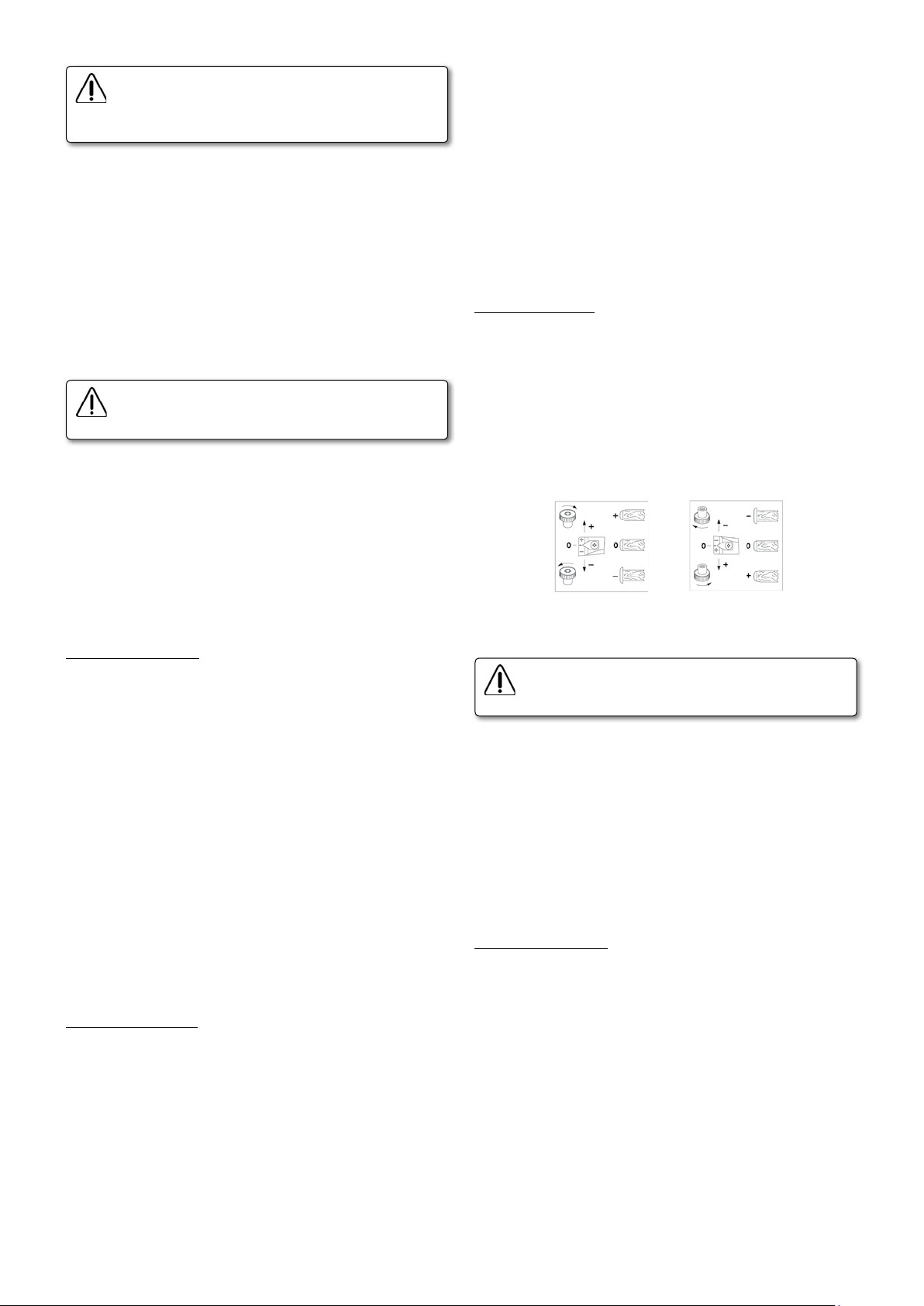
Ajuste del perfilador
La máquina va provista de una galga (Fig. 32) para ajustar las fresas y
situar los cabezales en la posición para fresar canto con radio o recto.
Situándola en la parte fina J4 (Fig. 32) se ajusta para radio, y situándola
por la parte gruesa K4 (Fig. 32) se ajusta para acabado recto.
Según el tipo de acabado a realizar en el tablero, para facilitar el ajuste
del perfilador y la selección del tipo de fresa a utilizar, existe una chapa
de indicaciones T2 (Fig. 5), con la representación esquematica de las
combinaciones que pueden efectuarse (Fig. 26).
Page 5
Perfilado con radio 3 mm, radio 2 mm, chaflán de 45ºx3 mm o
de 45ºx2 mm
Antes de ajustar el perfilador, desconectar la máquina
de la red eléctrica y bloquear el interruptor con la tapa
de seguridad K (Fig. 7)
Para tener acceso al perfilador y a los rascadores aflojar la manecilla
L1 (Fig. 22), y abrir el alimentador.
Retirar rascadores: Antes de proceder al ajuste del perfilador, es necesario retirar los rascadores, para que no interfieran en el proceso.
Para ello girar el pomo A1 (Fig. 10), hasta que el rascador I2 (Fig. 10),
quede unos 3 mm retirado del tablero.
Repetir el proceso con el rascador inferior, al cual accederemos por la
puerta delantera F3 (Fig. 14) procediendo de modo análogo.
Comprobar que las fresas que hay montadas en la máquina, son las
correspondientes al acabado que deseamos dar al canto y en caso contrario cambiarlas siguiendo las instrucciones explicadas en el apartado.
Prueba de perfilado:
• Para comprobar la corrección de los ajustes realizados en los
perfiladores, procederemos a cantear un tablero y a perfilarlo por
ambos lados. Antes de cantear el tablero, comprobaremos todos los
ajustes explicados en los apartados anteriores al Ajuste del perfilador,
asegurándonos que estén correctamente preparados. Si el acabado
conseguido no fuera totalmente satisfactorio en alguna de las caras,
podemos realizar los pequeños reajustes necesarios, actuando sobre
los palpadores superior o inferior C2 (Fig. 9), con el pomo Y (Fig. 9),
hasta obtener el acabado correcto.
InferiorSuperior
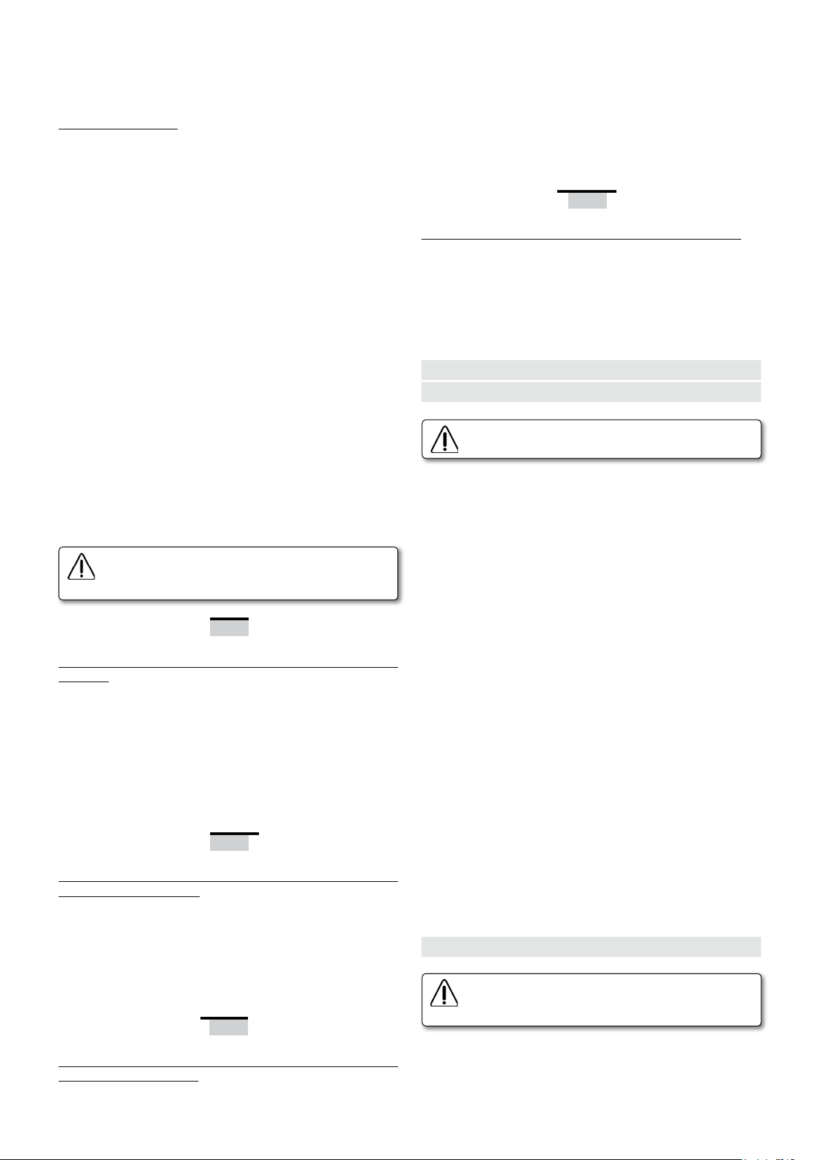
Perfilado recto a 10ºx1 mm, 10ºx2 mm o 10ºx3 mm
Ajuste de la fresa superior:
• A: Situar la galga M4 (Fig. 34) por la parte fina J4 (Fig. 32) en la
ranura K4 (Fig. 33), para fresar cantos con radio. Aflojar la varilla de
apriete D1 con la llave de servicio (Figs. 11b y 12) y desplazar el cabezal
superior hacia delante, con la ayuda del pomo B2 (Figs. 11a y 12),
girándolo en sentido horario (+) hasta que haga tope con la galga M4
(Fig. 34), sin forzarlo, es decir deteniéndonos en cuanto notemos que
aumenta su resistencia al giro, pues se habrá alcanzado ya la medida
y si se siguiera girando, se provocarían sólo deformaciones indeseables
en el mecanismo. Fijar el cabezal en esta posición, apretando de nuevo
la varilla de apriete D1 (Figs. 11 y 12).
• B: Para perfilar con radio 2, radio 3 o chaflán de 45ºx3, comprobar
que el palpador C2 (Fig. 9), se encuentra en la posición "0" (Fig. 9). Si
no estuviera en la posición "0", girar el pomo Y (Fig. 9), hasta hacer
coincidir las marcas "0" (Fig. 9) de referencia. Para perfilar con chaflán
de 45°x2, una vez situado el palpador coincidiendo las marcas "0" (Fig.
9) de referencia, lo bajaremos 1 mm accionando el pomo Y (Fig. 9) en
sentido antihorario (-), 1 vuelta entera.
• C: Aflojar los pomos B1 (Fig. 11 y 18) que fijan la altura del cabezal
y por medio del pomo X (Fig. 9.2), ajustar sobre el contador digital A4
(Fig. 9.2) la medida del grueso del tablero que vamos a cantear, fijando
de nuevo los pomos B1 (Figs. 11 y 18) en esa posición.
Ajuste de la fresa inferior:
• Para acceder al perfilador inferior se usarán el acceso delantero F3
(Fig. 14) y la puerta trasera F1 (Fig. 13) del mueble. Para su apertura,
bastará girar el perno E1 (Fig. 13).
• La puerta trasera permite el acceso a la manecilla D1 (Fig. 11b), a los
dos pomos B1 (Fig. 11c) y al pomo B2 (Fig. 11b). La puerta delantera
da acceso a los pomos de regulación X e Y (Fig. 9).
• Las regulaciones explicadas en este apartado, ajuste de la fresa
inferior, deben realizarse en el perfilador inferior, aunque se muestran
algunas imágenes del perfilador superior, por ser éste más visible y para
facilitar la comprensión.
• A: Comprobar que el cabezal inferior se encuentra a tope con la galga
M4 (Fig. 34), para ello aflojar la varilla de apriete con la llave de servicio
D1 (Fig. 11b) y retirar en primer lugar el cabezal hacia atrás, girando el
pomo B2 (Fig. 11b) un par de vueltas, con la ayuda del destornillador
allen de servicio, en sentido antihorario (-). A continuación girar el
pomo B2 (Fig. 11b), ahora en sentido horario (+), para llevar el cabezal
hacia delante, hasta hacer tope con la galga M4 (Fig. 34), pero sin
forzarlo, lo cual notaremos por el aumento de resistencia al giro de
dicho pomo.
varilla de apriete D1 (Fig. 11b).
Fijar el cabezal en esta posición, apretando de nuevo la
• B: Para perfilar con radio 2, radio 3 o chaflán de 45ºx3, comprobar
que el palpador inferior C2 (Fig. 9), se encuentra en la posición "0"
(Fig. 9). Si no estuviera en la posición "0", girar el pomo Y (Fig. 9) hasta
hacer coincidir las marcas "0" (Fig. 9) de referencia. Para perfilar con
chaflán de 45°x2, una vez situado el palpador coincidiendo las marcas
"0" (Fig. 9) de referencia, lo subiremos 1 mm accionando para ello el
pomo Y (Fig. 9) en sentido antihorario (-) 1 vuelta entera.
Antes de ajustar el perfilador, desconectar la máquina
de la red eléctrica y bloquear el interruptor con la tapa
de seguridad K (Fig. 7).
Para tener acceso al perfilador y a los rascadores aflojar la manecilla
L1 (Fig. 22), y abrir el alimentador.
Retirar rascadores: Antes de proceder al ajuste del perfilador, es
necesario retirar los rascadores, para que no interfieran en el proceso.
Para ello girar el pomo A1 (Fig. 10), hasta que el rascador I2 (Fig. 10),
quede unos 3 mm retirado del tablero.
Repetir el proceso con el rascador inferior, al cual accederemos por la
puerta delantera F3 (Fig. 14) procediendo de modo análogo.
Comprobar que las fresas que hay montadas en la máquina, son las
correspondientes al acabado que deseamos dar al canto, que en este
caso deberán ser fresas de radio 2 o de radio 3 y en caso contrario
cambiarlas siguiendo las instrucciones explicadas en el apartado 10.1
CAMBIO DE FRESAS DEL PERFILADOR.
Ajuste de la fresa superior:
• A: Aflojar la varilla de apriete D1 y retirar el cabezal superior girando
el pomo B2 (Figs. 11 y 12) con ayuda del destornillador allen de servicio,
en sentido anti-horario (-). Situar la galga M4 (Fig. 34) por la parte
gruesa hasta que se pueda encajar en el tope K4 (Fig. 33). Cuando se
haya encajado girar en sentido horario (+) hasta llegar a hacer tope
con la galga, sin forzarlo, deteniéndose cuando se note que aumenta
la resistencia al giro al haber alcanzado la situación de la fresa. Si
se siguiera girando se provocarían deformaciones indeseables en el
mecanismo. Fijarlo en esta posición, apretando de nuevo la varilla de
apriete D1 (Figs. 11 y 12).
• B: Situar el palpador superior a la altura conveniente. Para ello
comprobar primero que el palpador superior C2 (Fig. 9), se encuentra en
la posición "0" (Fig. 9). Si no estuviera en la posición "0", girar el pomo
Y (Fig. 9), hasta hacer coincidir las marcas "0" (Fig. 9) de referencia. A
continuación subir el palpador, girando el pomo Y (Fig. 9) en sentido
horario (+) en la siguiente proporción:
1/6 de vuelta................Para hacer chaflán de 1 mmx10º
1/3 de vuelta........................Para hacer chaflán de 2 mmx10º
1/2 vuelta..............................Para hacer chaflán de 3 mmx10º
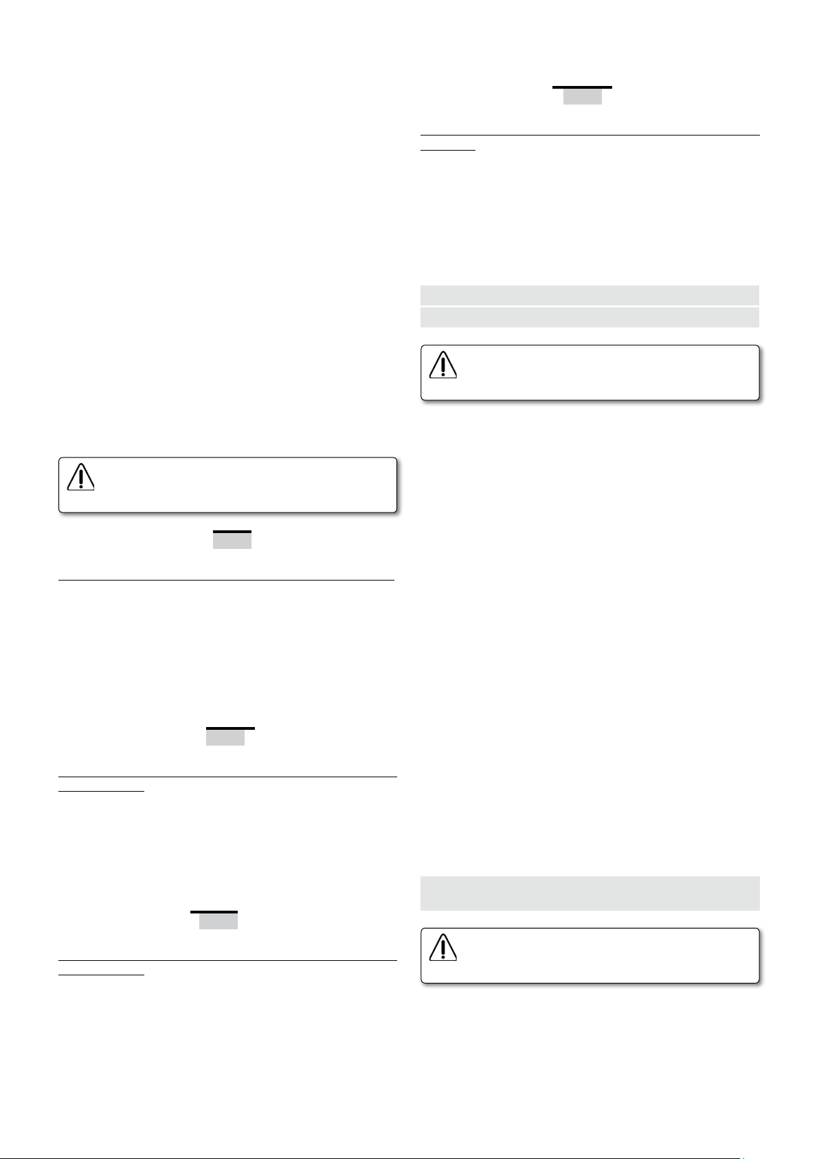
Para que esta regulación sea más sencilla, puede emplear el destornillador
allen de mango exagonal, que se entrega con las herramientas de la
máquina, usando la siguiente equivalencia.
1/6
1/3
1/2
5
Page 6

• C: Aflojar los pomos B1 (Figs. 11 y 18) que fijan la altura del cabezal
y por medio del pomo X (Fig. 9.2), ajustar sobre el índice A4 (Fig. 9.2),
la medida del grueso del tablero que vamos a cantear, fijando de nuevo
los pomos B1 (Figs. 11 y 18) en esa posición.
Ajuste de la fresa inferior:
• Para acceder al perfilador inferior se usarán la puertas delantera F3
(Fig. 14) y trasera F1 (Fig. 13) del mueble. Para su apertura, bastará
girar el perno E1 (Fig. 13 y 14).
• La puerta trasera permite el acceso a la varilla de apriete D1 (Fig.
11b), a los dos pomos B1 (Fig. 11c) y al pomo B2 (Fig. 11b). La puerta
delantera da acceso a los pomos de regulación X e Y (Fig. 9).
• Las regulaciones explicadas en este apartado, ajuste de la fresa inferior, deben realizarse en el perfilador inferior, aunque se muestran
algunas imágenes del perfilador superior, por ser éste más visible y
para facilitar la comprensión.
• A: Aflojar la varilla de apriere D1 y retirar el cabezal inferior girando
el pomo B2 (Figs. 11 y 12) con ayuda del destornillador allen de servicio,
en sentido anti-horario (-). Situar la galga M4 (Fig. 34) por la parte
gruesa hasta que se pueda encajar en el tope L4 (Fig. 33). Cuando se
haya encajado girar en sentido horario (+) hasta llegar a hacer tope
con la galga, sin forzarlo, deteniéndose cuando se note que aumenta
la resistencia al giro al haber alcanzado la situación de la fresa. Si
se siguiera girando se provocarían deformaciones indeseables en el
mecanismo. Fijarlo en esta posición, apretando de nuevo la varilla de
apriete D1 (Figs. 11 y 12).
• B: Situar el palpador inferior a la altura conveniente. Para ello comprobar primero que el palpador inferior C2 (Fig. 9), se encuentra en la
posición "0" (Fig. 9). Si no estuviera en la posición "0", girar el pomo
Y (Fig. 9) hasta hacer coincidir las marcas "0" (Fig. 9) de referencia. A
continuación bajar el palpador, girando el pomo Y (Fig. 9) en sentido
horario (+) en la siguiente proporción:
1/6 de vuelta.........................Para hacer chaflán de 1 mmx10º
1/3 de vuelta........................Para hacer chaflán de 2 mmx10º
1/2 vuelta.............................Para hacer chaflán de 3 mmx10º
Para que esta regulación sea más sencilla, puede emplear la llave
allen, que se entrega con las herramientas de la máquina, usando la
siguiente equivalencia.
1/6
1/3
1/2
Prueba de perfilado:
• Para comprobar la corrección de los ajustes realizados en los perfiladores, procederemos a cantear un tablero y a perfilarlo por ambos lados.
Antes de cantear el tablero, comprobaremos todos los ajustes explicados
en los apartados anteriores al ajuste del perfilador, asegurándonos que
estén correctamente preparados.
Si el acabado conseguido no fuera totalmente satisfactorio en alguna de
las caras, podemos realizar los pequeños reajustes necesarios, actuando
sobre los palpadores superior o inferior C2 (Fig. 9), con el pomo Y (Fig.
9), hasta obtener el acabado correcto.
Para regular el rascador, girar el pomo A1 (Fig. 10), hasta que el rascador
I2 (Fig. 10), roce ligeramente sobre el tablero, llevándose los restos de
cola y afinando la unión entre el tablero y el canto.
Para la regulación del rascador inferior, se accederá por la puerta delantera F3 (Fig. 14) de la máquina y se procederá de modo análogo.
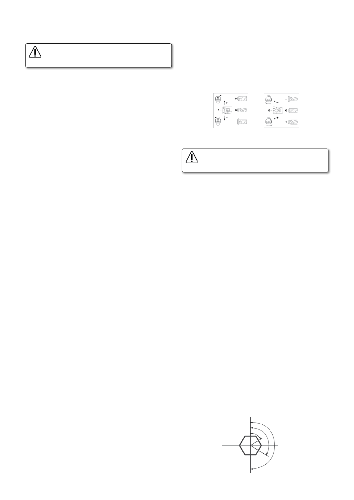
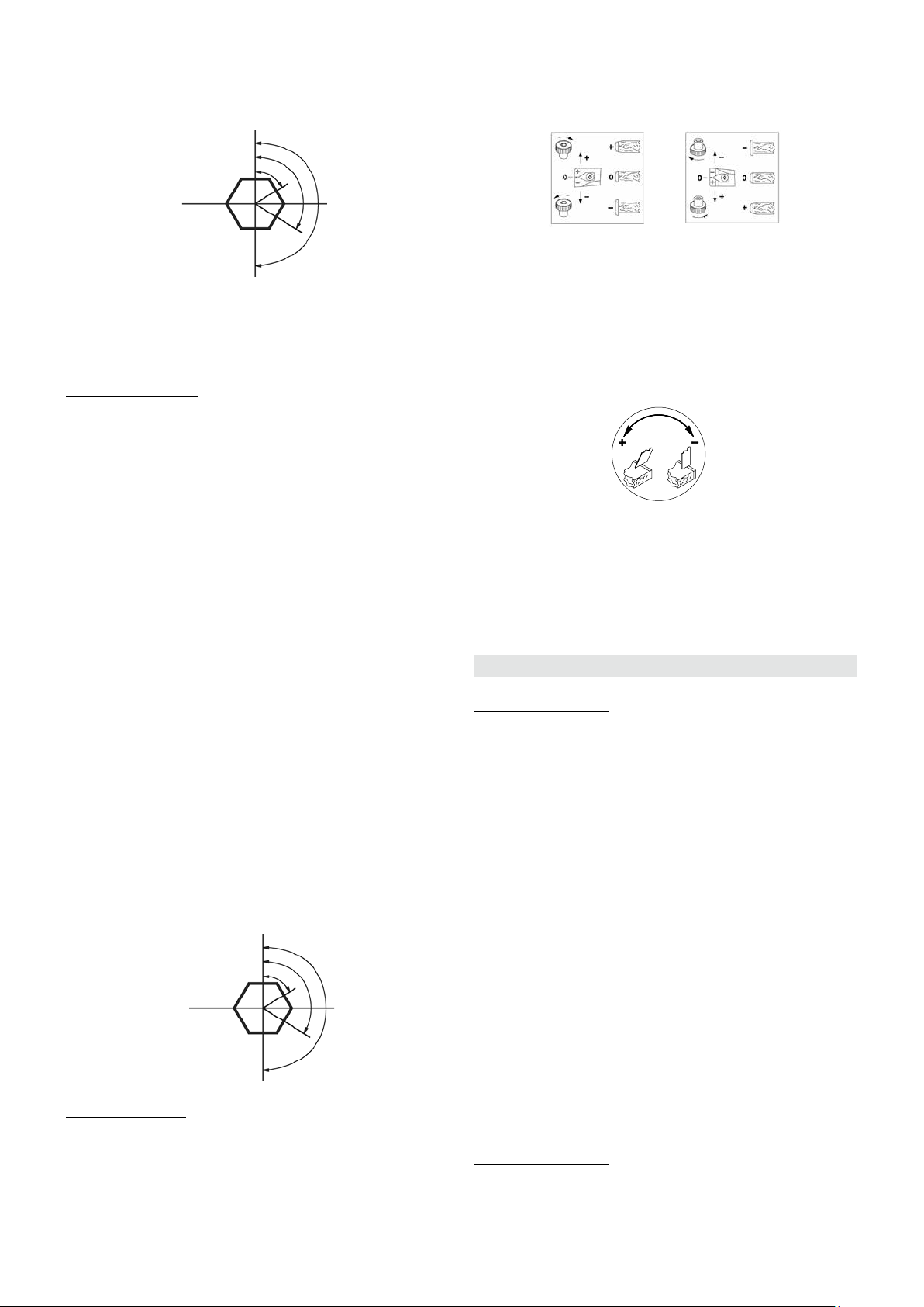
Regulación del sobrante trasero de canto:
Si al cantear un tablero con orden de retestado delantero y trasero,
es decir con el mando CM1 (Fig. 6) en la posición 1, queda sobrante o
falta en la parte trasera, puede corregirse para que quede al ras, con
un leve giro de la palanca A2 (Fig. 25), a derecha o izquierda, según se
indica en la placa (-, +) fijada en el mueble.
9. FUNCIONAMIENTO DE LA APLACADORA
• APLACADO DE CANTOS HASTA 1 mm
Situación de los mandos:
Palanca A (Fig. 6) en posición 1, para canto de 1 mm.
Mando CM1 (Fig. 6) en posición 1, retestado delantero y trasero.
Mando CM2 (Fig. 6) en posición 1, alimentador y control de temperatura
en marcha.
1. Colocar el tablero sobre la máquina, presionando sobre el frontal S
(Fig. 5), de la caja de mandos y avanzar hacia el alimentador para que
éste recoja el tablero y lo arrastre automáticamente.
2. Al presionar el tablero el microrruptor B (Fig. 21), comienza la
alimentación automática del canto.
3. Cuando el tablero llega al microrruptor E (Fig. 21), interrumpe la
alimentación automática del canto, continuando ésta por el arrastre
del propio tablero y pone en marcha el perfilador y el aspirador AS382L,
si está conectado.
4. Al alcanzar el tablero la cuchilla H (Fig. 21) del retestador, la desplaza
en la dirección de avance y efectúa el corte del sobrante de canto.
Retestado delantero.
5. Cuando el extremo trasero del tablero, suelta el microrruptor B (Fig.
21), estando el D (Fig. 21) presionado, se efectúa el corte del canto.
Retestado trasero.
6. El perfilador se detiene cuando el extremo trasero del tablero suelta
el microrruptor F (Fig. 21), deteniéndose también el aspirador al cabo
de unos segundos.
El ciclo de aplacado termina con la salida completa del tablero del
alimentador.
• APLACADO DE CANTOS GRUESOS 2 o 3 MM
Antes de realizar cualquier ajuste, deberá cambiarse de posición el
rodillo aproximación B2 (Fig. 27 y Fig. 28), bloquear con la varilla C2
y desenroscar el pomo D2. Intercambiar de posición el rodillo B2 con
el E2 y volver a montar de forma inversa (Fig. 28).
• APLACADO DE CANTOS DE 2 mm
Situación de los mandos:
Palanca A (Fig. 6) en posición 2, para canto entre 1 y 2 mm.
Mando CM1 (Fig. 6) en posición 1, retestado delantero y trasero.
Mando CM2 (Fig. 6) en posición 1, alimentador y control de temperatura
en marcha.
InferiorSuperior
Ajuste de los rascadores
Los rascadores deben regularse para cada tipo de tablero y siempre
con posterioridad a la regulación de los perfiladores.
6
El ciclo de funcionamiento del aplacado para éste canto, es idéntico al
APLACADO DE CANTOS HASTA 1 mm explicado mas arriba.
• APLACADO DE CANTOS DE 3 mm
Situación de los mandos:
Palanca A (Fig. 6) en posición 3, para canto entre 2 y 3 mm.
Mando CM1 (Fig. 6) en posición 4, corte del canto con sobrante delantero y trasero.
Page 7
Mando CM2 (Fig. 6) en posición 1, alimentador y control de temperatura en marcha.
1. Colocar el tablero sobre la máquina, presionando sobre el frontal S
(Fig. 5), de la caja de mandos y avanzar hacia el alimentador para que
éste recoja el tablero y lo arrastre automáticamente.
2. Al presionar el tablero el microrruptor B (Fig. 21), comienza la alimentación automática del canto.
3. Cuando el tablero llega al microrruptor E (Fig. 21), interrumpe la
alimentación automática del canto, continuando ésta por el arrastre
del propio tablero y pone en marcha el perfilador y el aspirador AS382L
si está conectado.
4. Al pulsar el tablero el microrruptor G (Fig. 21), se retrae la cuchilla H
(Fig. 21) del retestador, para dejar paso libre al tablero, sin retestarlo.
5. Cuando el extremo trasero del tablero, suelta el microrruptor B (Fig.
21), estando el F (Fig. 21) presionado, se efectúa el corte trasero del
canto con sobrante.
6. El perfilador se detiene cuando el extremo trasero del tablero suelta
el microrruptor F (Fig. 21), deteniéndose también el aspirador al cabo
de unos segundos.
Al soltar el extremo trasero del tablero el microrruptor G (Fig. 21), la
cuchilla del retestador queda libre para retornar a su posición inicial,
cuando el tablero la sobrepase, quedando terminada la operación de
canteado, con la salida del tablero del alimentador.
• RETESTADOS Y CORTES COMBINADOS
Cuando la máquina realiza el retestado delantero no
intente nunca levantar el protector, existe un grave
riesgo de accidente por acción de la cuchilla.
Retestados trasero y delantero: (Para cantos hasta 2 mm de espesor)
Mando CM1 (Fig. 6) en posición 1
1. Cuando el extremo trasero del tablero suelta los microrruptores B y
C (Fig. 21), estando el micro D (Fig. 21) presionado, se efectúa el corte
trasero del canto al ras del tablero, o retestado trasero.
Si el retestado trasero no queda al ras, vea el apartado de regulación
del sobrante trasero de canto, para corregirlo.
2. Al alcanzar el tablero la cuchilla H (Fig. 21) del retestador, la desplaza
en la dirección de avance y efectúa el corte del sobrante de canto.
Retestado delantero.
Retestado delantero y corte trasero con sobrante: (Para cantos hasta
2 mm de espesor)
Mando CM1 (Fig. 6) en posición 2
1. Cuando el extremo trasero del tablero suelta los microrruptores B y C
(Fig. 21), estando el micro D (Fig. 21) presionado, se efectúa el corte del
canto con un ligero retardo, dejando un sobrante en el trasero del tablero.
2. Al alcanzar el tablero la cuchilla H (Fig. 21) del retestador, la desplaza
en la dirección de avance y efectúa el corte del sobrante de canto.
Retestado delantero.
el sobrante delantero.
Corte con sobrantes delantero y trasero: (Para cantos de 2 a 3 mm
de espesor)
Mando CM1 (Fig. 6) en posición 4.
1. Cuando el extremo trasero del tablero suelta los microrruptores B y
C (Fig. 21), estando el micro D (Fig. 21) presionado, se efectúa el corte
del canto con un ligero retardo, dejando un sobrante en el trasero
del tablero.
2. Al pulsar el tablero el microrruptor G (Fig. 21), se retrae la cuchilla
H (Fig. 21) del retestador y deja pasar libremente el tablero sin cortar
el sobrante delantero.
10. MANTENIMIENTO Y LIMPIEZA
10.1 CAMBIO DE FRESAS DEL PERFILADOR
Para efectuar el cambio de las fresas, desconectar la
máquina de la red eléctrica y bloquear el interruptor
con la tapa de seguridad K (Fig. 7).
La fresa superior gira en sentido antihorario (-) y la inferior en sentido
horario (+), como se indica en el colector de virutas correspondiente
C4 (Fig. 9). Téngalo siempre en cuenta al efectuar un cambio de fresas.
Cambio de la fresa superior: Aflojar la manecilla L1 (Fig. 22) y abrir el
alimentador. Quitar los tornillos G1 (Fig. 17), retirar el conjunto palpador
H1 (Fig. 18) y bloqueando el eje de la fresa con la ayuda de la varilla
S1 (Fig. 19), quitar el tornillo I1 (Fig. 19) que fija la fresa, retirarla,
reemplazarla por otra nueva y volver a montar el conjunto palpador
H1 (Fig. 18), regulándolo a la altura conveniente para el acabado del
canto que vayamos a hacer, con la fresa que hemos montado, del modo
que se explica en los apartados de ajuste del perfilador.
Cambio de la fresa inferior: Para cambiar la fresa inferior es necesario
aflojar los pomos B1 (Fig. 11) del grupo perfilador inferior, accediendo
por la puerta trasera F1 (Fig. 13) y bajar el cabezal hasta el final con
ayuda del pomo X (Fig. 9 y 11). Para cambiar la fresa se procederá
del mismo modo que en el apartado anterior, pero debe tenerse en
cuenta que el tornillo I1 (Fig. 19) que sujeta la fresa inferior, es de
rosca izquierda. Una vez cambiada la fresa, subir de nuevo el cabezal
hasta el tope, con la ayuda del pomo X (Fig. 9) y regular el conjunto
palpador, para el acabado del canto que vayamos a hacer, con la fresa
que hemos montado, del modo que se explica en los apartados de
ajuste del perfilador.
Afilado de fresas: Las fresas deben afilarse, reproduciendo axialmente
la figura original, sin variar los diámetros (Fig. 24). Para montar la
fresa una vez afilada, deberán colocarse en el asiento del dorso de la
misma, tantas arandelas de 0.1mm 7080013 como sean necesarias, para
compensar el desplazamiento axial de la figura producido por el afilado.
10.2 CAMBIO DE LA CORREA DE
ARRASTRE DEL ALIMENTADOR
Retestado trasero y corte delantero con sobrante: (Para cantos hasta
2 mm de espesor)
Mando CM1 (Fig. 6) en posición 3.
1. Cuando el extremo trasero del tablero suelta los microrruptores B y
C (Fig. 21), estando el micro D (Fig. 21) presionado, se efectúa el corte
trasero del canto al ras del tablero, o retestado trasero.
Si el retestado trasero no queda al ras, vea el apartado de regulación
del sobrante trasero del canto
2. Al pulsar el tablero el microrruptor G (Fig. 21), se retrae la cuchilla
H (Fig. 21) del retestador y deja pasar libremente el tablero sin cortar
Para efectuar el cambio de correa, desconectar la
máquina de la red eléctrica y bloquear el interruptor
con la tapa de seguridad K (Fig. 7).
Quitar los tres tornillos T1 (Fig. 22), y retirar la tapa.
Aflojar la polea tensora U1 (Fig. 23), destensando la correa si es necesario.
Sustituir la correa V1 (Fig. 23) por otra original VIRUTEX S.A.,
comprobando su correcto engranaje con todas las poleas dentadas.
Tensar nuevamente la correa desplazando la polea tensora, con la
presión suficiente para que efectúe un buen arrastre en funcionamiento.
7
Page 8
10.3 LIMPIEZA Y RECOMENDACIONES
• Para obtener un buen corte del canto, debe trabajarse con las cuchillas
limpias de cola y bien afiladas.
• También la máquina, debe encontrarse limpia de cola y recortes de
canto, para evitar posibles atascos en el desplazamiento efectuado por
el canto preencolado.
• La presión que efectúe el alimentador sobre la superficie de los
tableros, debe ser la necesaria para el arrastre de los mismos. Una presión
excesiva, provoca un deterioro anticipado de la correa de arrastre.
• Es conveniente, que las superficies de los rodillos encoladores H2 (Fig.
10), y de la correa del alimentador, se mantengan limpias de restos de
cola y de partículas de material, a fin de obtener un arrastre adecuado
y un encolado perfecto.
• Para mantener limpias las fresas, se recomienda la utilización de
nuestro CANTSPRAY (espray antiadherente sin silicona).
• Cuando se utilicen maderas cortas, no deben empujarse con las
manos, sino con ayuda de un empujador.
10.4 LIMPIEZA DE LA GUÍA CANTO
Limpieza de la guía canto J4 (Figs. 29 y 29.2)
Si fuera necesario limpiar la guía canto J4 (Fig. 29.2), desmonte el
tornillo K4 (Fig. 29) con ayuda de la llave de servicio. Primero, tire de la
guía canto J4 (Fig. 29) hasta que se libere de los topes. Luego desplace
la guía J4 hacia la derecha (Fig. 29.2) y extráigala hacia el exterior (Fig.
29.2). Limpie la guía y proceda al montaje de la misma de modo inverso.
Para la limpieza de restos de cola se recomienda el uso de nuestro
spray limpiador NETSPRAY.
(1996). Las medidas de ruido han sido realizadas durante el proceso de
perfilado y retestado con canto de 3 mm. El nivel de ruidos en el puesto
de trabajo puede sobrepasar 85 dB (A). En este caso es necesario tomar
medidas de protección contra el ruido para el usuario de la máquina.
Otros factores que reducen la exposición de ruido son:
• Selección correcta de la herramienta.
• Mantenimiento adecuado de las herramientas y de la máquina.
• Empleo de sistemas apropiados de protección auditiva.
13. GARANTÍA
Todas las máquinas VIRUTEX, tienen una garantía válida de 12 meses a
partir del dia de su suministro, quedando excluidas todas las manipulaciones o daños ocasionados por manejos inadecuados o por desgaste
natural de la máquina. Para cualquier reparación, dirigirse al Servicio
Oficial de Asistencia Técnica VIRUTEX S.A.
VIRUTEX, se reserva el derecho de modificar sus productos sin previo
aviso.
ENGLISH
EDGEBANDER EB135 Rapid
(Pictures in page 41)
1.1. INSTRUCTIONS FOR SAFE HANDLING OF THE EDGEBANDER
11. CANTEADO DE TABLEROS ATAMBORADOS Y CANTOS
3D Y CRISTAL
Tableros atamborados o nido de abeja. (Fig. 35)
Para poder trabajar directamente con este tipo de tableros es muy
importante disminuir todo lo posible la presión del alimentador y de
los palpadores. Para tal efecto se procederá del siguiente modo:
- Disminuir la presión del alimentador (ver instrucciones ajuste
alimentador). Situar el alimentador entre 1/2 y 1 vuelta por encima
de la medida solicitada. Es decir si el tablero es de 19 mm, dejar el
alimentador entre 20 y 21 mm. Hay que tener en cuenta que la cinta
transportadora siempre debe presionar al tablero.
- Eliminar presión del perfilador (ver instrucciones ajuste perfilador
superior, ajuste fresa superior)
Situar el contador digital 0,5 y 0,8 mm por encima del de la medida del
tablero. Es decir si el tablero es de 19 mm, el contador deberá marcar
entre 19,5 y 19,8.
Hay que tener en cuenta que los palpadores siempre deberán estar
por debajo de la medida del tablero. En su defecto los palpadores no
copiarian el tablero y el trabajo no se realizaria satisfactoriamente.
Tambien deberá tener la precaucion de utilizar colas con alto coeficiente
de viscosidad, ya que este tipo de colas facilitan este tipo de pegado.
Cantos 3D y cristal (Fig. 36)
Para poder trabajar este tipo de canto, la maquina incorpora un
tratamiento de polimerización en el rodillo aplicador de cola, que
permite aplicar el minimo de cola posible.
Tambien deberá tener en cuenta que este tipo de canto es especialmente
sensible al calor y por este motivo deberán utilizarse colas de baja
fusión, máximo 140ºC.
Y por ultimo y no menos importante deberá utilizar el rodillo arrastre
de silicona en lugar del existente tal y como se indica en el apartado
8, montaje del rodillo arrastre.
12. NIVEL DE RUIDO
Los valores que se han medido de ruido son niveles de emisión y no
indican necesariamente un nivel de trabajo seguro. Los factores que
influyen en el nivel real de exposición del trabajador incluyen la duración
de la exposición, las características del lugar, otras fuentes de emisión
como el número de máquinas que hay instaladas, etc.
El ruido de esta máquina, se ha medido según la norma UNE-EN ISO3746
8
You will find the GENERAL SAFETY INSTRUCTIONS
leaflet with the documentation. Read this carefully
before using the machine.
• Before connecting the machine to the mains, ensure that the current
is the same as that specified on the characteristics plate.
o Always keep your hands away from the cutting area and hot parts.
• Always use proper carbide cutters and cutting blades. Never use any
that are defective or in poor condition.
• Do not override any of the machine's safety mechanisms.
• Before carrying out any maintenance on the machine, disconnect it
from the mains and lock safety cover K of switch box L (Fig. 7).
• Keep the supply cable in good condition.
• Never use the machine if it is not connected to a dust collection
system.
• Always use original VIRUTEX spare parts.
1.2. RECOMMENDATIONS BEFORE FIRST USING THE EB135
• The edge of the board to be banded must be at 90º to the top surface
and free of dust.
• The edge must have a good surface to obtain a perfect finish when
banding chip boards with thin edges.
• The pieces and the edges that are going to be glued must be at a
temperature of at least 18°C (64ºF).
• Always apply sufficient force on the edge to obtain a good banding.
• Check that the quantity of glue that the edge receives is appropriate
by doing a trial run.
• The glue tank must be closed and dry.
• The glue gives off fumes when at working temperature. Make sure
these are eliminated by keeping the workplace well ventilated.
• Keep the machine free of dust or shavings. If the machine is dirty
you will obtain bad quality veneers.
• Make sure you have enough fully melted glue in the tank to finish
the job.
• When you are going to glue the edges, use Virutex special glue for
ref. 2599266, which has been specially developed for this purpose.
• You can also use one of the following glues which have been
approved by Virute:
- Rayt type MA-6244
Page 9

- Kleiberit 743.7
- Kleiberit VP9296/57
- Jowat 280.3
Special for honeycomb pattern panels
-Quiadsa TM-1800
-Quiadsa TM1805
Special for 3D and glass effect tapes
- Dorus KS224/2
• Virutex only guarantees that edgebander PEB200/PEB250
will work correctly if one of the recommended glues are used.
1.3. GLUE CONSUMPTION AND APPROPRIATE EDGE (Fig. 37)
• See the diagram to the left, which shows the glue consumption given
the height of the edge, regardless of its thickness. For example: An edge
with a height of 23 mm consumes an average of 2.5 grams per metre.
• The diagram is also useful for identifying what type of edge can be
used given its height and thickness. For example: the maximum thickness that you can use is 3 mm x 25 m tall, or the maximum height
that you can use is 54 mm x 0.4 mm.
2. SPECIFICATIONS
Voltage.................................................................................................220-240 V
Input power…………….............................................…........................……...3450 W
Minimum edging thickness……….......................……...................13 mm (1/2")
Maximum board thickness (1-mm tape)...................................….50 mm (2")
Maximum board thickness (2-mm tape)…........................…......50 mm (2")
Maximum board thickness (3-mm tape)…..................….............22 mm (1")
Maximum trimmer capacity…........…......………..................……….3 mm (1/9")
Maximum front+end cutting capacity.......…….................……....2 mm (1/13")
Minimum board width…………..........................................................102 mm (4")
Minimum board length………….........................................……180 mm (7")
Electronic temperature regulation…..........................110º-200ºC (230-392 F)
Working speed…..………........................................................4m/min (13 feet/min)
Weight……………………………..........................................................150 kg (330 lbs)
Weighted equivalent continuous acoustic pressure level A........<80 dBA
Uncertainty..................................................................................................K = 3 dbA
Wear ear protection!
3. STANDARD EQUIPMENT
Inside the box you will find the following components:
1. EB135 Rapid Edgebander
2. Moveable support
3. Multiple pusher
4. A box containing:
• Dispenser
• Edge loader
• Set of keys
• Gauge
• Roller for 3D/glass effect tapes
5. Documentation
Optional tools:
Carbide cutter radius 3 and 10º bevel: upper 8540172, lower 8540173
(Fig. 2).
Carbide cutter radius 2 and 10º bevel: upper 8540183, lower 8540184
(Fig. 2). Included as standard.
Carbide cutter 45º bevel: upper 8540185, lower 8540186 (Fig. 2).
4. EDGEBANDER DIMENSIONS
(Fig. 1) shows the space occupied by the edgebander.
5. PRE-ASSEMBLY
ASSEMBLING THE MULTIPLE PUSHER
The machine has a multiple multiple pusher Q1 (Fig. 4), which must
fit into centring devices P1.
CONNECTING THE DUST COLLECTOR
The edgebander EB135 must not be used unless it is connected to an
external dust collection system, as the amount of shavings created
by the trimmer would adversely affect the trim quality, obstruct the
machine's mechanisms and shorten the life of the cutting tools.
We recommend our dust collector AS382L for edgebander EB135. This
has a high-powered vacuum and a large-capacity dust collector. It works
in accordance with the requirements of the machine, functioning only
during the trimming cycles.
To install the dust collector AS382L, connect the collection tube, which
is included, to collector C3 (Fig. 13.2) of the machine and connect its
remote control cable to base B3 (Fig. 13) of the machine. The dust collector must also be connected to an independent external power source.
To connect the machine's collector to a general installation with a
diameter of (4") 100 mm, order the optional attachment accessory
8545498, reducer with connectors (Fig. 16). The installation must have
an aspiration capacity of 1000 m
3
/h for the 100-mm (4") diameter.
6. CONNECTING TO THE MAINS
The machine must be connected to a monophase 220-240-V mains,
earthed and with a minimum capacity of 16 A, equipped with the
obligatory protection measures (magneto-thermal and differential).
Connect using the cable supplied.
7. DESCRIPTION OF THE CONTROLS
Control panel A3 of the machine is located nearby the loader R1 (Fig.
5). The general safety switch L is below this, on the side of the machine
housing (Fig. 5 and 7).
General safety switch L (Fig. 7): This is the general on/off switch for the
machine. It has magno-thermal protection, a minimum-voltage coil
and a safety-locking device for use during handling or repair of the
machine. Red indicator light M1 (Fig. 7) lights up when electrical power
is present. In the case of an electrical surge, the machine switches off
automatically, leaving all of its components without voltage.
Control panel A3 (Fig. 6): Green indicator light M (Fig. 6), lit when the
machine is on.
Temperature control Q (Fig. 6), enabling the user to control the glue
temperature.
Emergency stop button P (Fig. 6). When this button is pressed, all
functions of the machine are automatically stopped. To reverse the
action, turn stop button P in the direction shown by the arrow. The
machine cannot be turned on again using switch L (Fig. 5 and 7) if
emergency stop button P (Fig. 6) has not been deactivated.
Control CM1 (Fig. 6) for adjusting excess edge at the front and back
Position 1: For front and rear cutting. Both ends without excess.
Position 2: For front cutting, with excess at the back
Position 3: For rear cutting, with excess at the front
Position 4: With excess at both ends of the board
Control CM2 (Fig. 6):
Position 0: Feeder and temperature control disconnected.
Position 1: Turns on the feeder and the temperature control.
Position 2: Turns on only the feeder.
Temperature control: switches on the motor (at 30° C below the
temperature setpoint) and controls the operating temperature and
the temperature setpoint, assigned by the user.
After 1 hour after turning the machine automatically stops heating
and has to be reset with the main switch L (Fig. 3) to continue working.
8. MAKING ADJUSTMENTS AND TURNING THE MACHINE ON
ASSEMBLING THE LOADER
• Remove screws I (Fig. 3).
• Put loader R1 into place and fasten it with screws and washers I.
• Ensure that tape loader rollers N can turn freely.
Before carrying out any adjustments, disconnect the
machine from the mains and lock the switch using
safety cover K (Fig. 7).
9
Page 10
Placing the tape
Place a roll of tape into loader R1 (Fig. 5). The height should match the
thickness of the board to be edged. It is advisable that the edge be 3
mm (1/9") higher to obtain a perfect trim. Leaving any more excess
will result in a less satisfactory finish.
Selecting the tape thickness on control unit
Place lever A (Fig. 6) in the position that matches the thickness of the
selected edging:
Position 1: For tapes up to 1-mm thick.
Position 2: For tapes 1-2 mm thick.
Position 3: For tapes 2-3 mm thick.
To work with the machine set at position 3 (i.e., for tapes of 2-3 mm
thick), the user must also place excess adjustment control CM1 (Fig. 6)
in position 4, with excess at both ends of the board. This is because the
cutting quality at these thicknesses is not ideal for front and rear cutting.
(See COMBINED CUTTINGS.)
Selecting the tape thickness on tape presser unit
To adjust the gluing pressure of the tape regulate index D4 (Fig. 29) to
the corresponding tape thickness by means of the knob E4. If you are
working with very rigid tapes and more pressure is needed (i.e. with 3
mm PVC tapes) you can place the index at 2 or 2.5. Never adjust the
index over the tape thickness because there will be no enough glue
on the tape and the work would have a poor quality.
Fitting the feeding roller
Make sure that the feeding roller parts are fitted in the position indicated
in (Fig. 28), for banding edges of up to 1 mm thick, or as indicated in
(Fig. 27) for banding thick edges of 1 to 3 mm.
If the position of the rollers needs to be changed, block the rollers
with rod C2, unscrew knob D2, remove the rollers and re-fit them in
the correct position.
For 3D and glass effect tapes change the roller E2 and B2 complete by
the silicone one delivered together the machine accessories.
Adjusting the tape guide
Pass the pre-glued edging through guide W1 (Fig. 8), protector W2 (Fig. 8)
and between the two rollers, using knob T (Fig. 8) of the dragging roller.
Insert the edging between tape guide U (Fig. 8) and use knob V (Fig. 8) to
adjust the height of guide U (Fig. 8) to match the edging width. The edging
should be able to glide inside smoothly but should not move vertically.
If, while adjusting the tape guide, the edging needs to be reversed, use
lever C1 (Fig. 6.2 and 8) to release the pressure of the rollers on the
edging and pull on it, since the rollers only move in a forward direction.
Check again that the edging moves between guides U (Fig. 8) and leave
the end of the edging on the edge of the blade.
It never backs down with the tape once has contacted with the hot
glue since the tape guide can soiled and be cause of a bad operation
of the machine, having then to clean all the surface soiled by the glue.
Adjusting the feeder
Loosen levers J1 and L2 (Fig. 8 and 20). Turn wheel K1 (Fig. 20) until the
index of the feeder is at the correct position for the board thickness
required. Then tighten levers J1 and L2 (Fig. 8 and 20) in this position
If feeder J (Fig. 5 and 22) is opened, a safety device
will be activated. This disconnects the machine from
the mains. To turn it on again, close feeder J (Fig. 5)
and press general safety switch L (Fig. 7) once again.
Adjusting the amount of glue
Do this adjustment only when the machine is hot.
30) to increase or decrease the amount of glue (never turns this know
before the machine arrives to the temperature setpoint.
The machine is factory adjusted but if would be necessary to readjust
it, turn the knob F4 (Fig. 30) clockwise until the end of position "-"
(minimum amount of glue) and place the index between 6 and 8 for
an optimal thickness of glue.
Filling the glue pot
Do this adjustment only when the machine is hot.
Once the machine has warmed up (never lift the cover before it has reached the set temperature), the glue may be loaded in the following way:
Pull handle B4 (Fig. 10) as far as it will go and, using the dispenser N4
(Fig 10.1) and the hopper 04 (Fig. 10.1), load two doses the first time
to make the necessary adjustments and tests to the machine, once the
glue has melted. For large-scale jobs, two more doses may be added
for uninterrupted gluing work on 40 metres of edge, 23 mm in height.
By way of reference for reloading, observe the mark P4 (Fig. 10.3) at
approximately 1/3 of the tank from the top of the chute O4 (Fig. 10.1)
without stopping the machine; if the mark is visible, add two additional
loads using the dispenser N4 (Fig. 10.1) to glue another 40 metres. For
sporadic jobs, given the heating time (approx. 5 min) the tank does
not need to be filled to excess; it may be filled gradually as the glue
runs out, thus achieving good quality adhesion and saving on glue, as
deteriorated glue will never need to be removed.
In order to don't interrupt the work it is very important to avoid the
emptying of the glue pot. Make the recommended refills.
Regulating the moveable support
Loosen knobs N1 (Fig. 1). Place moveable support Q1 (Fig. 4 and 5) in
such a way that the board, when resting against guides R (Fig. 5), is
caught in multiple pusher Q1 (Fig. 4 and 5), against the face of control
box S (Fig. 5). Nonetheless, it must be able to slide between the two.
Tighten knobs N1 (Fig. 1) in this position.
Turning the machine on
Before turning the machine on, ensure that end of the
tape is at the edge of the blade H3 (Fig. 10.2) inside
the tape guide U (Fig. 8 and 10).
To switch on the power to the machine, press button O on general switch
L (Fig. 7). Green indicator light M (Fig. 6) will come on and the machine
will be ready. Place controls CM2 (Fig. 6) in position 1. The temperature
control and the feeder will remain on and both the excess cutting at
the ends and the trimmer will be ready for use during the work cycle.
To bring the machine to a complete stop, press right-hand button O
on general switch L (Fig. 7).
The machine cannot be turned on if emergency stop button P (Fig. 6)
has been activated, or if feeder J (Fig. 5 and 21) is open.
Temperature control
This machine is equipped with a digital temperature display. Here the
temperature of the glue can be set infinitely variable from 120° - 200°C
(230-392 F). First switch on the main switch of the machine. The lower
display (red) «SV» shows the currently set value. The upper display (green)
«PV» shows the current temperature of the hotmelt adhesive in the glue
pot. To change the temperature of the glue press the «FUNC» H4 (Fig.
31) button. The red display starts flashing. If you press this button again
you can use the buttons I4 (Fig. 31) to change the temperature at the
desired level. For confirmation press the «MODE» G4 (Fig. 31) button.
With of the adjusting knob F4 (Fig. 30) it is possible to control the
amount of glue to applied on the tape. Proceed as follows: As soon
as the machine is hot and the glue is melted, turn the knob F4 (Fig.
10
Once the temperature on the display has been reached,
wait for 5-10 minutes for the glue is to completely melt.
If you fill the glue pot with small quantities the heating
up time will be lower.
Page 11
To prevent burning your hands, do not touch hot parts
C4 (Fig. 21) while the machine is in use. To handle
the hot parts, turn the machine off and wait until the
temperature falls to below 40ºC (100°F).
Adjusting the trimmer
The machine is provided by a gauge (Fig. 32) to adjust the bits and the
trimming heads in the correct position to trimm tapes with radius or
straight. Placing it by the thin side J4 (Fig. 32) it is adjusted for timming
radius. By the thick side K4 (Fig. 32) it is adjusted for straight finishing.
There is an instructions plate T2 (Fig. 5) with a diagram showing the
possible combinations (Fig. 26) for the type of finishing required. This
is to facilitate adjustment of the trimmer and selection of the type
of bit to be used.
Trimming with a 3-mm radius, 2-mm radius, 45ºx3 mm bevel or
45ºx2 mm bevel.
Before adjusting the trimmer, disconnect the machine
from the mains and lock the switch using safety cover
K (Fig. 7).
To gain access to the trimmer and scrapers, loosen lever L1 (Fig. 22)
and open the feeder.
Removing the scrapers: Before proceeding to adjust the trimmer, remove
the scrapers so that they do not get in the way. To do this, turn knob A1
(Fig. 10) until scraper I2 (Fig. 10) is around 3 mm away from the board.
Repeat the procedure with the lower scraper. This can by accessed via
front door F3 (Fig. 14). Proceed in the same manner.
Ensure that the carbide cutters in the machine are the right kind for
the desired finish. If not, change them according to the instructions
set out in section.
Adjusting the upper bit:
• A: Place the gauge M4 (Fig. 34) by the thin side J4 (Fig. 32) in the
groove K4 (Fig. 33), to trimm tapes with radius, loosen tightening rod
D1 with the service spanner (Fig. 11b and 12) and move the upper
head forward, using knob B2 (Fig. 11a and 12), turning clockwise (+)
until it just reaches the gauge M4 (Fig. 34), but without forcing it.
Stop when you notice increased resistance to turning, as the limit A
(Fig. 12) will then have been reached and any further turning would
result in undesired de-formation of the mechanism. Fix the head in
this position by tightening rod D1 (Fig. 11 and 12) once again.
• B: To trim with a radius of 2 or 3 or a bevel of 45ºx3, ensure that
copying device C2 (Fig. 9) is at position "0" (Fig. 9). If not, turn knob Y
(Fig. 9) to bring it down to meet reference marks "0" (Fig. 9). To trim
with a bevel of 45ºx2, once the copying device has been positioned to
coincide with reference marks "0" (Fig. 9), lower the copying device
1 mm by giving knob Y (Fig. 9) one full turn in a counterclockwise
(-) direction.
• C: Loosen knobs B1 (Fig. 11 and 18) which set the height of the head,
and use knurled knob X (Fig. 9.2) to adjust on counter A4 (Fig. 9.2)
the thickness of the board to be banded. Fix knobs B1 (Fig. 11 and 18)
once again in this position.
Adjusting the lower bit:
• To gain access to the lower trimmer, use the front opening F3 (Fig.
14) and rear door F1 (Fig. 14) and F1 (Fig. 13) of the machine stand.
To open, simply slide back bolt E1 (Fig. 13).
• The back door provides access to lever D1 (Fig. 11b) and to the two
knobs B1 (Fig. 11c), as well as to knob B2 (Fig. 11b). The front door
gives access to regulating knobs X and Y (Fig. 9).
• The adjustments explained in this section, Adjusting the lower cutting blade, are to be carried out on the lower trimmer. However, in
the illustrations, we have used some times the upper trimmer, as it is
more clearly visible and therefore easier to understand.
• A: Check that the lower head is at its limit against the gauge M4
(Fig. 34). To do this, loosen tightening rod D1 with the service spanner
(Fig. 11b) and first move the head back, using the Allen screw driver
to give knob B2 (Fig. 11 b) a couple of turns in a counterclockwise (-)
direction. Then turn knob B2 (Fig. 11b) clockwise (+) to bring the head
forward until it just reaches its limit against the gauge M4 (Fig. 34).
Do not force it - you will notice increased resistance to the turning of
the afore-mentioned knob. Fix the head in this position by tightening
rod D1 (Fig. 11b) once again.
• B: To trim with a radius of 2 or 3 or a bevel of 45ºx3, ensure that
lower copying device C2 (Fig. 9) is at position "0" (Fig. 9). If it is not,
turn knob Y (Fig. 9) to bring it up to meet reference marks "0" (Fig.
9). To trim with a bevel of 45ºx2, once the copying device has been
positioned to coincide with reference marks "0" (Fig. 9), raise it 1 mm by
giving knob Y (Fig. 9) one full turn in a counterclockwise (-) direction.
Testing the trimming:
• To ensure that the adjustments made to the trimmers are correct,
edgeband a board and trim it on both sides. To do this, you will need
to set switch CM3 (Fig. 6) at position 1.
Before edgebanding the board, ensure that all of the adjustments set
out in the sections leading up to Adjusting the trimmer have been
carried out correctly.
If the finish is not entirely satisfactory on any of the edges, whatever
small readjustments are necessary can be made using knob Y (Fig. 9)
to adjust upper or lower copying devices C2 (Fig. 9), until the correct
finish is achieved.
LowerUpper
Straight trimming - 10ºx1mm, 10ºx2mm or 10ºx3mm
Before adjusting the trimmer, disconnect the machine
from the mains and lock the switch using safety cover
K (Fig. 7).
To gain access to the trimmer and scrapers, loosen lever L1 (Fig. 22)
and open the feeder.
Removing the scrapers: Before proceeding to adjust the trimmer, remove
the scrapers so that they do not get in the way. To do this, turn knob A1
(Fig. 10) until scraper I2 (Fig. 10) is around 3 mm away from the board.
Repeat the procedure with the lower scraper. This can by accessed via
front door F3 (Fig. 14). Proceed in the same manner.
Ensure that the carbide cutters in the machine are the right kind for
the desired finish. In this instance, the correct carbide cutters are radius
2 or radius 3. If they are not the right kind, change them according
to the instructions set out in section 10.1 CHANGING THE CUTTERS.
Adjusting the upper bit:
• A: Loosen the tightening rod D1 and remove the upper head by turning the knob B2 (Figs. 11 and 12) using the service allen screwdriver
in counterclockwise (-). Place the gauge M4 (Fig. 34) on the thicker
side until it can fit into the stopper K4 (Fig. 33). When fitted it, rotate
clockwise (+) until the gauge stop, without forcing it, stopping when
you notice that increases the resistance to rotation having attained
the bit position. Do not force, any further turning would result in
undesired de-formation of the mechanism. Fix it in this position again
tightening rod D1 (Figs. 11 and 12).
• B: Place the upper copying device at the correct height. To do this,
first ensure that upper copying device C2 (Fig. 9) is set at position
"0" (Fig. 9). If it is not, turn knob Y (Fig. 9) to bring it down to meet
reference marks "0" (Fig. 9). Then raise the copying device by turning
knob Y (Fig. 9) in a clockwise direction (+), in the following proportions:
1/6 of a turn…….….............................for a bevel of 1 mmx10º
1/3 of a turn…….………....................for a bevel of 2 mmx10º
1/2 a turn……………..................…….for a bevel of 3 mmx10º
11
Page 12
To facilitate this regulation, we recommend using the hexagonal Allen
screwdriver, which is supplied with the tools belonging to this machine.
Employ the following equivalence:
1/6
small readjustments are necessary can be made using knob Y (Fig.
9) to adjust the upper or lower copying devices C2 (Fig. 9), until the
correct finish is achieved.
1/3
1/2
• C: Loosen knobs B1 (Fig. 11 and 18), which set the height of the
head, and using knurled knob X (Fig. 9.2), adjust on index A4 (Fig. 9.2)
the thickness of the board to be edgebanded. Fix knobs B1 (Fig. 11
and 18) in this position.
Adjusting the lower bit:
• To gain access to the lower trimmer, use front F3 (Fig. 14) and back
F1 (Fig. 13) doors of the machine housing. To open, simply slide back
bolt E1 (Fig. 13 and 14).
• The back door allows the user to gain access to tightening rod D1
(Fig. 11b) and to the two knobs B1 (Fig. 11c), as well as to knob B2
(Fig. 11b). Through the front door, the user can gain access to the
regulating knobs X and Y (Fig. 9).
• The adjustments explained in this section, Adjusting the lower cutting blade, are to be carried out on the lower trimmer. However, in
the illustrations, we have used some times the upper trimmer, as it is
more clearly visible and therefore easier to understand.
• A: Loosen the tightening rod D1 and remove the lower head by turning the knob B2 (Figs. 11 and 12) using the service allen screwdriver
in counterclockwise (-). Place the gauge M4 (Fig. 34) on the thicker
side until it can fit into the stopper L4 (Fig. 33). When fitted it, rotate
clockwise (+) until the gauge stop, without forcing it, stopping when
you notice that increases the resistance to rotation having attained the
bit position. Do not force, any further turning would result in undesired
de-formation of the mechanism. Fix it in this position again tightening
rod D1 (Figs. 11 and 12).
• B: Place the lower copying device at the correct height. To do this,
first ensure that lower copying device C2 (Fig. 9) is set at position "0"
(Fig. 9). If it is not, turn knob Y (Fig. 9) to meet the reference marks
"0" (Fig. 9). Then lower the copying device by turning knob Y (Fig. 9)
in a clockwise direction (+), in the following proportions:
1/6 of a turn………....................…...for a bevel of 1 mmx10º
1/3 of a turn…….....................………..for a bevel of 2 mmx10º
1/2 a turn……...................…………….for a bevel of 3 mmx10º
To facilitate this regulation, we recommend using the Allen key, which
is supplied with the tools belonging to this machine. Employ the following equivalence:
1/6
1/3
LowerUpper
Adjusting the scrapers:
The scrapers should be adjusted to suit each type of board, always after
the trimmers have been regulated.
To regulate the scraper, turn knob A1 (Fig. 10) until scraper I2 (Fig.
10) lightly rubs against the board, honing the joint between the board
and the edging.
The lower scraper is accessed using front door F3 (Fig. 14) of the machine. Proceed in the same manner.
Regulating excess edging at the back:
If when edgebanding a board with front and back cutting flush with
the board there is too much or too little edging at the back, the cut
can be adjusted so that it is flush, by giving the lever A2 (Fig. 25) a
slight turn in the direction required. Turn towards the "minus" (-)
mark for less excess and towards the "plus" (+) mark to increase the
amount of excess.
9. HOW TO USE THE EDGEBANDER
• EDGEBANDING EDGES UP TO 1 mm
Position of the controls:
Lever A (Fig. 6) in position 1, for 1-mm edges
Switch CM1 (Fig. 6) in position 1, front and back cutting
Switch CM2 (Fig. 6) in position 1, feeder and temperature control on
1. Place the board on the machine. Press on front panel S (Fig. 5) of
the control box and move towards the feeder so that it will take in
the board and convey it automatically.
2. When the board presses on micro-switch B (Fig. 21), automatic
feeding of the edging begins.
3. When the board reaches micro-switch E (Fig. 21), automatic feeding
of the edging is interrupted. This continues being dragged by the board,
and the trimmer and dust collector AS382L (if connected) start up.
4. As the board reaches blade H (Fig. 21) of the front cutting, it moves
it forwards and cuts the excess edging. Front cutting.
5. When the back end of the board releases micro-switch B (Fig. 21),
the edging is cut. Rear cutting.
6. The trimmer stops when the back end of the board releases microswitch F (Fig 21). The dust collector also switches off after a few seconds.
The edgebanding cycle is complete when the board has fully exited the feeder.
1/2
Testing the trimming:
• To ensure that the adjustments made to the trimmers are correct,
edgeband a board and trim it on both sides. To do this, you will need
to set the switch CM3 (Fig. 6) at position 1.
Before edgebanding the board, ensure that all of the adjustments set
out in the sections leading up to Adjusting the trimmer have been
carried out correctly.
If the finish is not entirely satisfactory on any of the edges, whatever
12
• EDGEBANDING THICK EDGES OF 2, 3 MM
Before making any adjustments, change the position of the approach
roller B2 (Fig. 27 and Fig. 28), lock it with the rod C2 and unscrew the
knob D2. Switch the position of rollers B2 and E2 and remount in the
inverse order (Fig. 28).
• EDGEBANDING EDGES OF 2 mm
Position of the controls:
Lever A (Fig. 6) in position 2, for edges of between 1 and 2 mm
Switch CM1 (Fig. 6) in position 1, front and rear cutting flush with
the board
Switch CM2 (Fig. 6) in position 1, feeder and temperature control on
Page 13
The working cycle of the edgebander for this type of edging is identical
to that set out in EDGEBANDING EDGES UP TO 1 mm, as explained above.
• EDGEBANDING EDGES OF 3 mm
Position of the controls:
Lever A (Fig. 6) in position 3, for edges of between 2 and 3 mm
Switch CM1 (Fig. 6) in position 4, cutting the edging with excess at
front and back
Switch CM2 (Fig. 6) in position 1, feeder and temperature control on
1. Place the board on the machine. Press on front panel S (Fig. 5) of
the control box and move towards the feeder so that it will take in
the board and convey it automatically.
2. When the board presses on micro-switch B (Fig. 21), automatic
feeding of the edging begins.
3. When the board reaches micro-switch E (Fig. 21), automatic feeding
of the edging is interrupted. This continues being dragged by the board,
and the trimmer and dust collector AS382L (if connected) start up.
4. When the board triggers micro-switch G (Fig. 21), blade H (Fig. 21)
of the end cutting unit retracts to let the board pass through without
front cutting.
5. When the back end of the board releases micro-switch B (Fig. 21),
being switch F (Fig. 21) pressed, the rear end of the edging is cut.
6. The trimmer stops when the back end of the board releases microswitch F (Fig. 21), and the dust collector also switches off after a few
seconds.
When micro-switch G (Fig. 21) is released by the back end of the board,
the blade of the front cutting is free to return to its initial position
when the board has passed through. The edgebanding cycle is complete
when the board has fully exited the feeder.
• FRONT AND REAR COMBINED CUTTINGS
Never try to raise the protector when the machine is
carrying out a front cut. The blade is very dangerous
and could easily cause an accident.
Front and rear cutting flush with the board: (For edging of up to 2
mm thick)
Switch CM1 (Fig. 6) in position 1.
1. When the back end of the board releases micro-switches B and C
(Fig. 21), being micro-switch D (Fig. 21) pressed, the edging is cut at
the back, flush with the board. Rear cutting.
If the rear cutting is not flush with the board, see Regulating the excess
at the back of the edging to correct the fault.
2. When board front reaches the blade H (Fig. 21), it moves it forward
and the excess edging at the front is cut flush with the board. Front
cutting.
1. When the back end of the board releases micro-switches B and C
(Fig. 21), being micro-switch D (Fig. 21) pressed, the edging is cut flush
with the board at the back. Rear cutting.
If the rear cutting is not flush with the board, see regulating the excess
at the back of the edging.
2. When the board presses micro-switch G (Fig. 21) blade H (Fig. 21)
of the front cutting retracts and lets the board pass through, without
cutting the excess at the front.
Front and rear cutting with excess: (For edging of 2-3 mm thick)
Switch CM1 (Fig. 6) in position 4.
1. When the back end of the board releases micro-switches B and C
(Fig. 21), being micro-switch D (Fig. 21) pressed, the edging is cut at the
back with a slight delay and an excess is left at the back of the board.
2. When the board presses micro-switch G (Fig. 21), blade H (Fig. 21)
of the front cutting retracts and lets the board pass through, without
cutting the excess at the front.
10. MAINTENANCE AND CLEANING
10.1 CHANGING THE CUTTERS
Before changing the bits, disconnect the machine from
the mains and lock the switch using safety cover K (Fig. 7).
The upper carbide cutter turns in a counterclockwise direction (-) and
the lower, in a clockwise direction (+), as shown on shavings collector
C4 (Fig. 9). Always keep this in mind when changing the carbide cutters.
Changing the upper cutter: Loosen the lever L1 (Fig. 22) and open
the feeder. Remove screws G1 (Fig. 17), take out copying device H1
(Fig. 18) and, using rod S1 (Fig. 19) to lock the spindle of the carbide
cutter, remove screw I1 (Fig. 19) which holds the carbide cutter in place.
Replace the old carbide cutter with a new one and put copying device
set H1 (Fig. 18) back together again, adjusting the height to suit the
finish of the edging with the carbide cutter inserted, as explained in
Adjusting the trimmer.
Changing the lower cutter: Gaining access via rear door F1 (Fig. 13),
loosen knobs B1 (Fig. 11) of the lower trimmer. Acceding now through
front door F3 (Fig.14) bring the head all the way down, with the aid
of knurled knob X (Fig. 9 and 11). To change the carbide cutter, proceed in the same way as described in the previous section, but bear in
mind that screw I1 (Fig. 19) has a left-hand thread. Once the carbide
cutter has been changed, raise the head fully once again, with the aid
of knurled knob X (Fig. 9), and regulate the copying device set to suit
the finish of the edging with the carbide cutter inserted, as explained
in Adjusting the trimmer.
Front cutting flush with the board and rear cutting with excess: (For
edging of up to 2-mm thick)
Switch CM1 (Fig. 6) in position 2.
1. When the back end of the board releases micro-switches B and C
(Fig. 21), being micro-switch D (Fig. 21) pressed, the edging is cut at the
back with a slight delay and an excess is left at the back of the board.
2. When blade H (Fig. 21) of the front cutting unit is reached by the
board, it moves it forward and the excess edging is cut flush with the
board. Front cutting.
Rear cutting flush with the board and front cutting with excess: (For
edging of up to 2 mm thick)
Switch CM1 (Fig. 6) in position 3.
Sharpening the carbide cutters: The carbide cutters should be sharpened, reproducing the original shape axially, without altering the
diameters (Fig. 24). To replace a carbide cutter that has been sharpened,
place as many 0.1-mm 7080013 washers as are necessary on the seat
at the back of the blade to compensate for the axial displacement
caused by the sharpening process.
10.2 CHANGING THE FEEDER BELT
Before changing the belt, disconnect the machine
from the mains and lock the switch using safety cover
K (Fig. 7).
Remove three screws T1 (Fig. 22) and take off the cover.
Loosen jockey wheel U1 (Fig. 23).
Replace belt V1 (Fig. 23) with a new VIRUTEX S.A. original, ensuring
that it engages correctly with the toothed wheels. Tighten the jockey
13
Page 14
wheel, applying the necessary amount of pressure for a good dragging
motion and finally replace de cover K (Fig. 7).
10.3 CLEANING AND RECOMMENDATIONS
• To achieve a good clean edging cut, always keep the blades sharp
and free of glue.
• The machine itself should also be kept free of glue build-up and
edging trimmings, to prevent edging jamming.
• The feeder should apply the correct amount of pressure to the surface
of the boards so that these may be conveyed. Excessive pressure leads
to premature deterioration of the feeder belt.
• We recommend keeping the surfaces of gluing roller H2 (Fig. 10)
and of the feeder belt clean and free of glue build-up and particles of
material, in order to achieve a correct board conveying and a perfect
result when gluing.
• To keep the cutters and blades clean, we recommend the use of our
CANTSPRAY (a silicone-free non-stick spray).
• When using short pieces of wood, do not push with your hands. Use
a pushing device.
10.4 CLEANING OF THE TAPE GUIDE
Cleaning the tape guide J4 (Figs. 29 and 29.2)
If you need to clean the tape guide J4 (Fig. 29.2), remove the screw
K4 (Fig. 29) using the service key. First, pull the tape guide J4 (Fig. 29)
until it releases the stops. Then slide to the right the guide J4 (Fig.
29.2) and pull outwards (Fig. 29.2). Clean the guide and proceed to
assemble it in reverse.
To clean the glue residue is recommended our spray cleaner NETSPRAY.
11. BANDING HONEYCOMB PANELS AND 3D AND GLASS
EFFECT TAPES
Honeycomb pattern panels. (Fig. 35)
To work directly with this type of panels is very important to reduce
as much as possible feeder and copiers pressure. To do this proceed
as follows:
- Reduce feeder pressure (see instructions feeder adjustment).
Place the feeder between 1/2 to 1 turn over the requested thickness.
That is, if the board is 19 mm, leaves the feeder between 20 and 21
mm. Keep in mind that the feeding belt must always press the board.
- Reduce trimming unit pressure (see instructions trimming unit setting,
adjusting upper bit).
Place the digital counter 0.5 and 0.8 mm above the measurement
of the board. That is, if the board is 19 mm, the counter should read
between 19.5 and 19.8.
Keep in mind that the copiers should always be below the panel thickness. Otherwise they would not copy the panel and the work would
not be carried out successfully .
Also take care to use glues with high coefficient of viscosity, since this
type of glues facilitate this type of banding.
3D and glass effect tapes (Fig. 36)
To band this kind of tapes, the machine incorporates a polymerisation
treatment on roller glue applicator, which applies the minimum possible
amount of glue.
Also should be noted that this type of tapes are particularly sensitive
to heat and for this reason should be used low melt glues, maximum
140° C (284 F).
And last but not least you must use the silicone feeding roller instead
of the existing one as indicated in section 8 fitting the feeding roller.
12. NOISE LEVELS
The measured noise level values are emission levels and do not necessarily
reflect a safe working level. Factors influencing the real noise exposure level experienced by the operator include the exposure duration,
characteristics of the location, other sources of emission, such as the
number of machines installed, etc.
The noise from this machine has been measured according to regulation
UNE-EN ISO3746 (1996). Noise measurements were taken during the
14
trimming and end cutting process, with a 3 mm edge. The noise level
at the work station may exceed 85 dB(A). In this case, the machine
operator should take protective measures against noise.
Other factors that reduce noise exposure are:
• Selecting the correct tool.
• Adequate tool and machine maintenance.
• The use of appropriate hearing protection systems.
13. WARRANTY
All VIRUTEX machines are guaranteed for 12 months from the date of
supply, excluding any damage which is a result of incorrect use or of
natural wear and tear on the machine. All repairs should be carried
out by the official VIRUTEX technical assistance service.
VIRUTEX reserves the right to modify its products without prior notice.
FRANÇAIS
PLAQUEUSE DE CHANTS PRÉENCOLLÉS EB135
Rapid
(FIGURES EN PAGE 41)
1.1. INSTRUCTIONS DE SÉCURITÉ POUR LE
MANIEMENT DE LA PLAQUEUSE
Lire attentivement la BROCHURE DES INSTRUCTIONS
GÉNÉRALES DE SÉCURITÉ jointe à la documentation
de la machine.
• Vérifier avant de brancher la machine si la tension d'alimentation
correspond à celle indiquée sur la plaque des caractéristiques.
• Toujours maintenir les mains éloignées des zones de coupe et des
zones chauffantes.
• Ne jamais utiliser de fraises et de couteaux incorrects, défectueux
ou en mauvais état.
• Ne pas annuler les mécanismes de sécurité de la machine.
• Pour toute manipulation de maintenance de la machine, la débrancher du secteur et fermer le couvercle de sécurité K du boîtier de
l'interrupteur L (Fig. 7).
• Conserver le câble d'alimentation en bon état.
• Ne pas utiliser la machine sans la brancher à un système d'aspiration.
• Toujours utiliser des pièces de rechange d'origine VIRUTEX.
1.2. RECOMMANDATIONS DONT IL FAUT TENIR COMPTE
AVANT DE COMMENCER À UTILISER LA PLAQUEUSE EB135
• Le chant du panneau à plaquer doit former un angle de 90º par
rapport à la surface du panneau. Il doit être propre sans poussière.
• Lors du placage de chants peu épais sur des panneaux de particules,
la surface du chant du panneau doit être le plus lisse possible pour
obtenir une bonne finition.
• Les pièces et les chants à encoller doivent être à température ambiante, supérieure à 18° C (64ºF).
• Pour un bon placage, toujours faire une pression suffisante contre
le chant.
• Vérifier que la quantité de colle que reçoit le chant est suffisante,
en faisant un essai sur un échantillon.
• Le bac à colle doit être bien fermé et sec.
• La colle dégage des vapeurs quand la machine est à la température
de fonctionnement. Bien ventiler le lieu de travail, pour assurer leur
élimination.
• Bien nettoyer la machine pour éliminer la poussière ou les copeaux. Une
machine sale ne pourra produire que des placages de mauvaise qualité.
• Vérifier qu'il y a assez de colle complètement fondue dans le bac
pour achever le travail.
• Au moment d’encoller les chants, utilisez la colle spéciale Virutex
pour ref. 2599266 conçue à cet effet.
• Vous pouvez également employer l’une des colles suivantes, homo-
Page 15

loguées par Virutex:
- Rayt MA-6244
- Kleiberit 743.7
- Kleiberit VP9296/57
- Jawat 280.3
Spéciale pour panneaux nid d'abeille
- Quiadsa TM-1800
- Quiadsa TM-1805
Spéciale pour chants 3D et verre
- Dorus KS224/2
• Virutex ne garantit le bon fonctionnement de la plaqueuse que si
elle est employée avec l’une des colles recommandées.
1.3. CONSOMMATION DE COLLE EN FONCTION DU CHANT
(Fig. 37)
• Le graphique ci-contre illustre la consommation de colle en fonction
de la hauteur du chant quelle que soit son épaisseur. Exemple: un
chant d’une hauteur de 23 mm consomme en moyenne 2,5 grammes
de colle par mètre.
• Le graphique permet également de déterminer le type de chant
à utiliser en fonction de sa hauteur et de son épaisseur maximales.
Exemple: si l’épaisseur maximale du chant à utiliser est de 3 mm, sa
hauteur maximale doit être de 25 mm. Si sa hauteur maximale est de
54 mm, son épaisseur maximale doit être de 0,4 mm.
2. CARACTÉRISTIQUES TECHNIQUES
Tension...........................................................................................220 - 240 V
Puissance absorbée........................................................................3450 W
Largeur min. à plaquer..................................................................13 mm
Largeur max. à plaquer (1 mm épaisseur)......................................50 mm
Largeur max. à plaquer (2 mm épaisseur).....................................50 mm
Largeur max. à plaquer (3 mm épaisseur).....................................22 mm
Capacité maximum unité d'arasage....................................3 mm
Capacité maximum éboutage.........................................................2 mm
Largeur minimum du panneau.........................................................102 mm
Longueur minimum du panneau........................................................180 mm
Réglage électronique de la température.................................110°-200ºC
Vitesse de travail.....................................................................................4 m/min
Poids.....................................................................................................150 kg
Niveau de pression acoustique continu équivalent pondéré A......<80 dBA
Incertitude..........................................................................K = 3 dbA
Porter une protection acoustique!
3. ÉQUIPEMENT STANDARD
En ouvrant la caisse d'emballage, vous trouverez les éléments suivants:
1. Plaqueuse de chants préencollés EB135 Rapid
2. Ensemble rallonge de table
3. Ensemble presseur multiple
4. Caisse contenant:
• Doseur
• Dévidoir du chant
• Jeux de clés
• Cale pour unité d'affleurage
• Rouleau pour chant 3D/verre
5. Documentation.
Fraises en option:
Fraise en métal dur, rayon 3 et chanfrein de 10º: supérieur 8540172,
inférieur 8540173, (Fig. 2).
Fraise en métal dur, rayon 2 et chanfrein de 10º: supérieur 8540183,
inférieur 8540184, (Fig. 2). Incluse d'origine
Fraise en métal dur, chanfrein de 45º: supérieur 8540185, inférieur
8540186, (Fig. 2).
4. DIMENSIONS DE LA PLAQUEUSE
L'espace occupé par la plaqueuse est représenté sur la (Fig. 1).
5. ASSEMBLAGES PRÉALABLES
MONTAGE DU DÉVIDOIR
• Dévisser les vis I de leur logement, (Fig. 3).
• Placer le dévidoir R1 et le fixer avec les vis et les rondelles I.
• Vérifier si les rouleaux N du chargeur de bande tournent librement.
MONTAGE DU ENSEMBLE PRESSEUR
La machine dispose d'un ensemble presseur Q1 (Fig. 4), qui devra
s’encastrer sur les centreurs P1.
BRANCHEMENT DE L'ASPIRATION
Il ne faut pas travailler sur la machine EB135 sans la brancher sur
un système d'aspiration externe, car la quantité de copeaux produits
par les unités d'arasage réduirait la qualité de l'arasage, obstruerait
les mécanismes de la machine et détériorerait les outils de coupe
prématurément.
Nous conseillons d'employer pour la plaqueuse EB135 notre aspirateur
AS382L, d'une grande puissance d'aspiration et d'une grande capacité
de réservoir, adapté pour répondre aux commandes de la machine, ne
travaillant que pendant les cycles d'arasage.
Pour l'installation de l'aspirateur AS382L, il faut brancher le tuyau
d'aspiration dont il est pourvu au collecteur C3 (Fig. 13.2), de la
machine et son câble de commande à distance à la base B3 (Fig. 13),
de la machine. Il faut brancher l'aspirateur sur une prise de courant
externe indépendante.
Si vous souhaitez brancher l'aspiration de la machine sur une installation
générale de 100 mm de diamètre, commandez le raccord optionnel
8545498, réducteur de 100 avec connecteurs, (Fig. 16). L'installation
devra avoir une aspiration de 1000 m3/h pour le diamètre de 100 mm.
6. BRANCHEMENT ÉLECTRIQUE
La machine doit être branchée par le câble fourni, sur une installation
électrique monophasée de 220-240 V, d'une capacité minimale de 16 A
et pourvue d'une prise de terre et des dispositifs de protection réglementaires (interrupteur magnéto-thermique et interrupteur différentiel).
7. DESCRIPTION DES COMMANDES DE CONTRÔLE
Le panneau de contrôle de la machine A3 est situé près du dévidoir
R1 (Fig. 5), et l'interrupteur général de sécurité L, sous celui-ci sur le
côté du meuble, (Fig. 5 et 7).
Interrupteur général de sécurité L (Fig. 7): Interrupteur général de mise
en marche de la machine. Pourvu de protection thermomagnétique,
bobine à tension minimum et système de blocage de sécurité, pour
la manipulation ou la réparation de la machine. Indicateur lumineux
rouge M1 (Fig. 7), allumé en présence de courant électrique. En cas de
surcharge électrique, il disjoncte et déconnecte automatiquement la
machine et tous les éléments.
Panneau de contrôle A3 (Fig. 6): Indicateur lumineux vert M (Fig. 6),
allumé quand la machine est en marche.
Bouton régulateur de température Q (Fig. 6), qui permet de régler la
température de la colle.
Bouton-poussoir d'arrêt d'urgence P (Fig. 6), muni d'un verrouillage
qui arrête immédiatement toutes les fonctions de la machine. Pour le
débloquer, il faut tourner le bouton-poussoir P dans le sens de la flèche.
La machine ne pourra pas être remise en marche avec l'interrupteur
L (Fig. 5 et 7), si le bouton-poussoir d'arrêt d'urgence P (Fig. 6), n'a
pas été débloqué.
Commande CM1 (Fig. 6), de réglage de l'excédent de chant sur les
extrémités avant et arrière.
En position 1: Coupe avant et arrière. Sans excédent aux deux extrémités.
En position 2: Coupe avant, avec excédent sur la partie arrière.
En position 3: Coupe arrière, avec excédent sur la partie avant.
En position 4: Avec excédent aux deux extrémités du panneau.
Commande CM2 (Fig. 6):
En Position 0: Dispositif d'entraînement et contrôle de température
déconnectés.
En Position 1: Mise en marche du dispositif d'entraînement et contrôle
de température.
15
Page 16
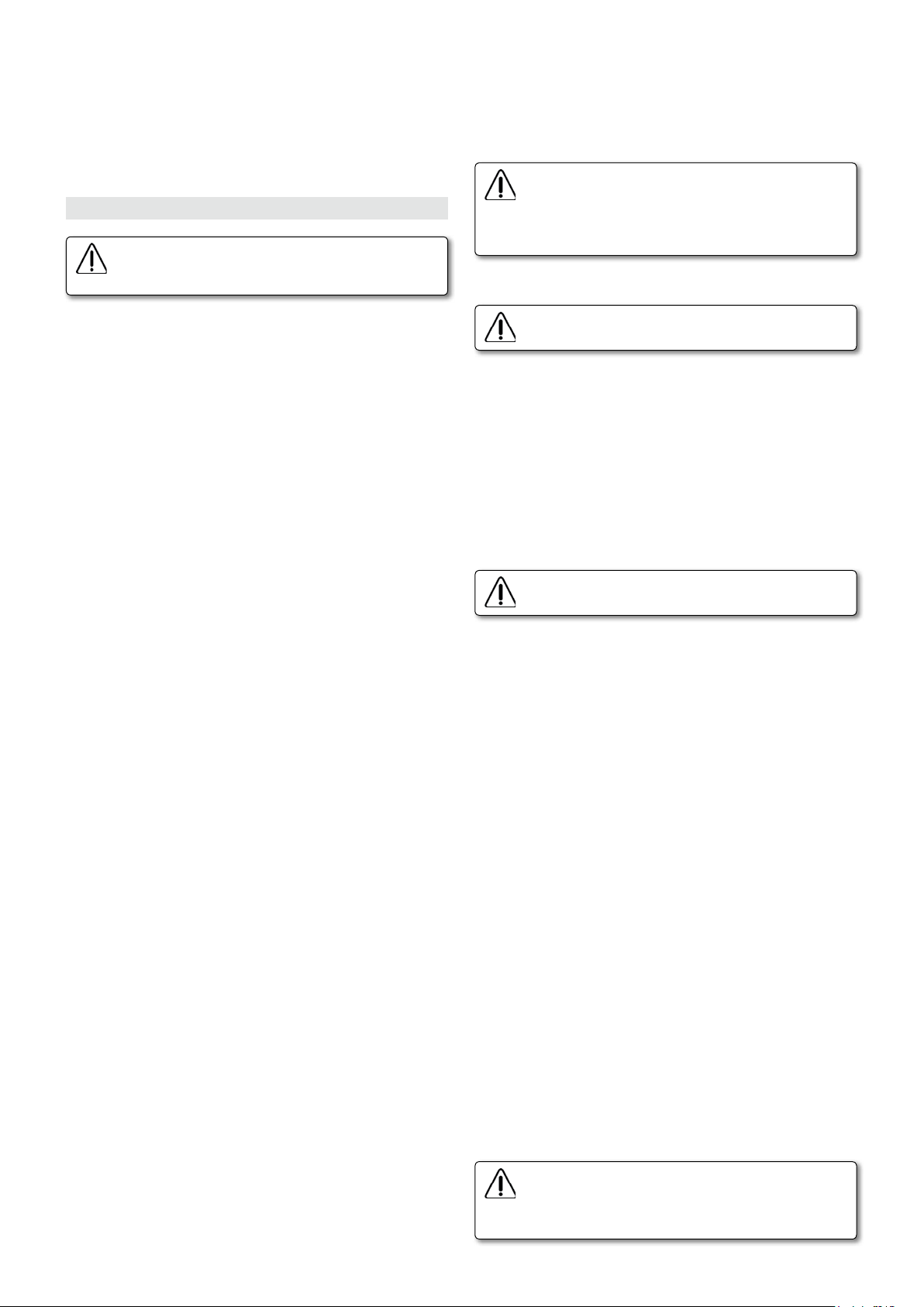
En Position 2: Mise en marche uniquement du dispositif d'entraînement.
contrôle de température: met en marche le moteur de la colle (à 30 ºC
au-dessous de la température de consigne), contrôle la température de
travail et la température de consigne, donnée par l’utilisateur.
Une heure après sa mise en marche, la machine s’arrête de chauffer
automatiquement et il est nécessaire de la réarmer avec l'interrupteur
général L (Fig. 3) pour continuer le travail.
8. RÉGLAGES ET MISE EN MARCHE
Avant de faire tout réglage, débrancher la machine du
secteur et couvrir l'interrupteur avec le couvercle de
sécurité K (Fig. 7).
Réglage du dispositif d'ntraînement
Desserrer les manettes J1 et L2 (Fig. 8 et 20). Tourner le volant K1 (Fig.
20), pour situer le sélecteur du dispositif d'entraînement sur la mesure
correspondant à l'épaisseur du panneau et resserrer les manettes J1 et
L2 (Fig. 8 et 20), dans cette position.
Quand on ouvre le dispositif d'entraînement J (Fig. 5 et
22), un dispositif de sécurité est actionné pour débrancher la machine du secteur. Pour la remettre en marche,
fermer le dispositif d'entraînement J (Fig. 5), et actionner
de nouveau l'interrupteur général de sécurité L (Fig. 7).
Réglage du débit de colle
Mise en place du chant
Placer un rouleau de chant dans le dévidoir R1 (Fig. 5). La hauteur
du chant doit correspondre à l'épaisseur du panneau à plaquer, il est
recommandé que le chant ait une hauteur 3 mm plus grande que
l'épaisseur du panneau, pour obtenir un arasage parfait. Si on laisse
plus d'excédent, la finition ne sera pas correcte.
Sélection de l'épaisseur du chant sur le panneau de contrôle
Placer le levier A (Fig. 6), du sélecteur, sur la position correspondant à
l'épaisseur de chant à plaquer:
Position 1: Pour chants d'une épaisseur jusqu'à 1mm.
Position 2: Pour chants d'une épaisseur entre 1 et 2 mm.
Position 3: Pour chants d'une épaisseur entre 2 et 3 mm.
Pour travailler en position 3, c'est-à-dire pour plaquer avec des chants
d'une épaisseur entre 2 et 3 mm, il faut mettre aussi la commande de
réglage d'excédent CM1 (Fig. 6), sur la position 4, avec excédent aux
deux extrémités du panneau, car la qualité de coupe dans ces épaisseurs
n'est pas appropriée pour une coupe en bout parfaite.
(Voir paragraphe coupes en bout et en arrière COMBINÉES)
Sélection de l'épaisseur du chant sur le presseur chant
Pour régler la pression d’encollage du chant, il faut situer le sélecteur D4
(Fig. 29) sur l’épaisseur de chant correspondant, à l’aide du bouton E4. En cas
d’utilisation de chants très rigides nécessitant plus de pression sur le chant,
par exemple un chant de 3 mm en PVC, le sélecteur peut être situé sur 2 ou
2,5. Ne jamais situer le sélecteur au-dessus de l’épaisseur du chant, car la
colle n’imprégnerait pas bien le chant et le travail serait de mauvaise qualité.
Montage du rouleau d'entraînement
Vérifier si les éléments du rouleau d'entraînement sont bien montés
dans la position indiquée sur la (Fig. 28), pour plaquer des chants fins
d'une épaisseur de jusqu'à 1 mm ou dans la position indiquée sur la
(Fig. 27), pour plaquer des chants d'une épaisseur de 1 à 3 mm
Pour changer la position des rouleaux en cas de besoin, bloquer le
rouleau avec la tige C2, dévisser le bouton D2, retirer les rouleaux et
les remonter dans la position correcte.
Pour des chants 3D ou verre, changer le rouleau E2 et B2 complet par
le rouleau en silicone livré comme accessoire avec la machine.
Réglage du guidage de bande
Passer le chant préencollé dans le guidage W1 (Fig. 8), le protecteur
W2 (Fig. 8), et entre les deux rouleaux, à l'aide du bouton T (Fig. 8), du
rouleau d'entraînement. Introduire le chant entre le guidage de bande
U (Fig. 8), et régler avec le bouton V (Fig. 8), la hauteur du guidage
U (Fig. 8), sur la largeur du chant de manière à ce que celui-ci glisse
doucement à l'intérieur sans se déplacer verticalement.
Pour faire reculer le chant au cours du réglage du guidage de bande,
il faut actionner le levier C1 (Fig. 6.2 et 8), pour libérer la pression des
rouleaux sur celui-ci et tirer dessus, car les rouleaux ne tournent que
dans le sens de l'avance.
Vérifier de nouveau le glissement du chant dans les guidages U (Fig. 8),
et placer l'extrémité du chant sur le tranchant du couteau.
Ne jamais faire reculer le chant une fois que celui-ci est entré en
contact avec la colle chaude, cela souillerait le guidage de bande en
provoquant un mauvais fonctionnement, il faudrait alors nettoyer
obligatoirement toute la surface souillée par la colle.
16
Le réglage du débit de colle doit être effectué uniquement lorsque la machine est chaude.
Le bouton de réglage du débit F4 (Fig. 30) permet de contrôler la quantité de colle à appliquer sur le chant. Procéder comme suit: lorsque la
machine est chaude et la colle fondue, tourner le bouton F4 (Fig. 30)
pour diminuer ou augmenter la quantité de colle (ne jamais tourner
le bouton avant que la température de consigne ne soit atteinte). La
machine est réglée d’origine, néanmoins si un nouveau réglage devait
être nécessaire, tourner le bouton F4 (Fig. 30) dans le sens des aiguilles
d’une montre, jusqu’à la butée de la position "-" (débit minimum), puis
situer le sélecteur entre 6 et 8 pour une correcte épaisseur de colle.
Remplissage de la colle dans le bac
Le remplissage de la colle doit être effectué uniquement
lorsque la machine est chaude.
Une fois que la machine est chaude (ne jamais tirer sur le couvercle
avant d’atteindre la température de consigne), on peut réaliser le
remplissage de colle comme suit:
tirer sur la poignée B4 (Fig. 10) jusqu’à sa butée, puis remplir à l’aide du
doseur N4 (Fig. 10.1), par l’entonnoir O4 (Fig. 10.1), 2 doses la première
fois pour faire les réglages et les essais nécessaires de la machine. Une
fois la colle fondue et en cas de production intensive, il est possible
d’ajouter 2 doses supplémentaires et d’encoller ainsi en continu chaque
40 mètres de chant de 23 mm de large sans interruption.
Comme référence pour de nouveaux remplissages, observer depuis
la partie supérieure de l’entonnoir O4 (Fig. 10.1) le repère à 1/3 du
réservoir environ, sans arrêter la machine; si le repère P4 (Fig. 10.3)
est visible, ajouter de nouveau deux doses à l’aide du doseur N4 (Fig.
10.1) pour encoller 40 mètres de plus. Pour les travaux sporadiques, et
étant donné la vitesse de chauffe (5 min env.), il n’est pas nécessaire de
trop remplir le réservoir, puisqu’il est possible de faire le plein au fur et
à mesure que la colle est utilisée. Ceci permet d’obtenir un encollage
de bonne qualité tout en faisant des économies de colle puisqu’il n'y
aura jamais de colle détériorée à retirer.
Afin d’éviter toute interruption du processus de production, il est
important de ne pas laisser le bac à colle se vider. Effectuer les remplissages recommandés.
Réglage du guidage extensible
Desserrer les boutons N1 (Fig. 1). Situer le guidage extensible Q1 (Fig. 4
et 5), de manière à ce que la station de presse Q1 (Fig. 4 et 5), comprime
le panneau, appuyé sur les guidages R (Fig. 5), contre la face frontale
du tableau de commandes S (Fig. 5), tout en lui permettant de glisser
entre les deux et serrer les boutons N1 (Fig. 1), dans cette position.
Mise en marche:
Avant de mettre la machine en marche, vérifier que le
bord du chant doit être situé sur le tranchant du couteau H3 (Fig. 10.2), à l'intérieur du guidage de bande
U (Fig. 8 et 10).
Page 17

Appuyer sur le bouton-poussoir O de l'interrupteur général L (Fig. 7),
pour mettre la machine sous tension. L'indicateur lumineux vert M
(Fig. 6), s'allume et la machine est branchée. Mettre en position 1 les
commandes CM2, (Fig. 6), ceci met en marche le contrôle de température
et le dispositif d'entraînement et les coupes aux extrémités et l'unité
d'arasage sont prêts à fonctionner dans le cycle de travail.
L'arrêt total de la machine se fait en appuyant sur le bouton-poussoir
droit O de l'interrupteur général L (Fig. 7).
La machine ne peut pas être mise en marche si le bouton-poussoir d'arrêt
d'urgence P (Fig. 6), est enclenché ou si le dispositif d'entraînement J
(Fig. 5 et 22), est ouvert.
Contrôle de la température:
Cette machine est équipée d’un contrôle de température numérique.
Ce contrôle permet de régler la température de la colle sans interruption de 120ºC à 200ºC. Actionner tout d’abord l’interrupteur principal
de la machine. L’écran inférieur (rouge) «SV» affiche la température
programmée. L’écran supérieur (vert) «PV» affiche la température réelle
de la colle dans le bac.
Pour modifier la température de la colle, appuyer sur le bouton «FUNC»
H4 (Fig. 31). L’écran rouge se mettra à clignoter. En appuyant de
nouveau sur ce bouton, la température peut être modifiée au niveau
voulu à l’aide des boutons I4 (Fig. 31). Pour terminer, appuyer sur le
bouton «MODE» G4 (Fig. 31).
Une fois que la température voulue s’affiche à l’écran,
patienter 5 à 10 minutes pour que la colle fonde
complètement. En effectuant de petits remplissages,
la vitesse de chauffe sera plus rapide.
Ne pas toucher les parties chaudes C4 (Fig. 21), pendant
le fonctionnement, on peut se brûler les mains. Pour
manipuler les parties chaudes, débrancher la machine et
attendre que la température baisse en dessous de 40ºC.
Réglage de l'unité d'arasage
La machine est pourvue d’une cale (Fig. 32) permettant de régler les
fraises et de situer les têtes en position d'affleurage du chant avec
une finition en rayon ou droite. En la plaçant par le côté fin J4 (Fig.
32), les fraises et les têtes sont réglées pour une finition en rayon et,
en la plaçant par le côté épais K4 (Fig. 32), elles sont réglées pour une
finition droite.
Selon de type de finition à réaliser sur le panneau, pour faciliter le
réglage de l'unité d'arasage et la sélection du type de fraise à utiliser,
il existe une plaque d'indications T2 (Fig. 5) avec la représentation
schématique des combinaisons que l'on peut effectuer (Fig. 26).
Arasage à rayon 3 mm, rayon, 2 mm, chanfrein de 45ºx3 mm ou
de 45ºx2 mm.
serrage D1 avec la clé de service (Fig. 11b et 12), et la déplacer la tête
supérieure vers l'avant, à l'aide du bouton B2 (Fig. 11a et 12), en le
faisant tourner dans le sens des aiguilles d’une montre (+) jusqu'à faire
butée avec la cale M4 (Fig. 34), sans le forcer, en s'arrêtant quand on
détecte que la résistance à tourner augmente, car le reglage sera déjà
fait et si on continue à tourner, on risque de déformer le mécanisme.
Fixer la tête dans cette position, en resserrant la tige de serrage D1
(Fig. 11 et 12).
• B: Pour araser avec le rayon 2, rayon 3 ou le chanfrein de 45ºx3,
vérifier si le palpeur C2 (Fig. 9), se trouve en position "0", (Fig. 9). S'il
n'est pas en position "0" tourner le bouton Y (Fig. 9), jusqu'à ce que
les repères de référence "0", (Fig. 9), coïncident. Pour araser avec un
chanfrein de 45ºx2, après avoir mis en place le palpeur en faisant coïncider les repères de référence "0", (Fig. 9), baisser le palpeur de 1 mm
en tournant pour ce faire le bouton Y (Fig. 9), dans le sens contraire
des aiguilles d'une montre (-) 1 tour entier.
• C: Desserrer les boutons B1 (Fig. 11 et 18), qui fixent la hauteur de
la tête et avec le bouton X (Fig. 9.2), régler sur le compteur sico A4
(Fig. 9.2), la mesure de l'épaisseur de panneau à plaquer, en fixant de
nouveau les boutons B1 (Fig. 11 et 18), dans cette position.
Réglage de la fraise inférieure:
• L'accès à l'unité d'arasage inférieure se fait par l'accès avant F3 (Fig.
14), et la porte arrière F1 (Fig. 13), du meuble. Pour les ouvrir, il suffit
de tourner le maneton E1 (Fig. 13 et 14).
• La porte arrière permet d'accéder à la vis D1 (Fig. 11b), aux deux
boutons B1 (Fig. 11b), et au bouton B2 (Fig. 11b). La porte avant permet
d'accéder aux boutons de réglage X et Y (Fig. 9).
• Les réglages expliqués dans ce paragraphe, réglage de la fraise inférieure, doivent être réalisés sur l'unité d'arasage inférieure, mais pour
faciliter la compréhension, il est montré les images de l'unité d'arasage
supérieure car elle est plus visible.
• A: vérifier si la tête inférieure se trouve en butée avec la cale M4
(Fig. 34), si ce n'est pas le cas, desserrer la tige de serrage avec la clé
de service D1 (Fig. 11b) et déplacer la tête vers l'arrière en faisant
tourner le bouton B2 (Fig. 11b) de deux tours, avec le tournevis Allen
de service, dans le sens contraire des aiguilles d'une montre (-). Ensuite
la déplacer vers l'avant, à l'aide du bouton B2 (Fig. 11b), en le tournant
dans le sens des aiguilles d'une montre (+) jusqu'à faire butée avec la
cale M4 (Fig. 34), sans le forcer, en s'arrêtant quand on détecte que
la résistance à tourner augmente. Fixer la tête dans cette position, en
resserrant la tige de serrage D1 (Fig. 11b).
• B: Pour araser avec le rayon 2, rayon 3 ou le chanfrein de 45ºx3,
vérifier si le palpeur inférieur C2 (Fig. 9), se trouve en position "0" (Fig.
9). S'il n'est pas en position "0" tourner le bouton Y (Fig. 9) jusqu'à ce
que les repères de référence "0" (Fig. 9), coïncident. Pour araser avec
un chanfrein de 45ºx2, après avoir mis en place le palpeur en faisant
coïncider les repères de référence "0", (Fig. 9), monter le palpeur de 1
mm en tournant pour ce faire le bouton Y (Fig. 9), dans le sens contraire
des aiguilles d'une montre (-) 1 tour entier.
Avant de régler l'unité d'arasage, débrancher la machine
du secteur et couvrir l'interrupteur avec le couvercle
de sécurité K (Fig. 7).
Pour avoir accès à l'unité d'arasage et aux racloirs, desserrer la manette
L1 (Fig. 22), et ouvrir le dispositif d'entraînement.
Retirer les racloirs: avant de faire le réglage de l'unité d'arasage, il faut
retirer les racloirs, pour qu'ils n'interfèrent pas dans le réglage. Pour
ce faire, tourner le bouton A1 (Fig. 10), pour déplacer le racloir I2 (Fig.
10), de 3 mm par rapport au panneau.
Répéter l'opération avec le racloir inférieur, on y accède par la porte
avant F3 (Fig. 14), en faisant de même que pour le supérieur.
Vérifier si les fraises montées sur la machine correspondent à la finition
que l'on veut donner au chant, si ce n'est pas le cas, les changer en
suivant les instructions données dans le paragraphe.
Réglage de la fraise supérieure:
• A: Placer la cale (Fig. 34) par le côté fin J4 (Fig. 32) dans la rainure
K4 (Fig. 33), pour affleurer des chants avec rayon. Desserrer la tige de
Essai d'arasage:
• Pour vérifier la correction des réglages réalisés sur les unités d'arasage,
il faut effectuer le placage d'un panneau en l'arasant des deux côtés.
Avant de plaquer le panneau, il faut vérifier tous les réglages expliqués
dans les paragraphes précédant le réglage de l'unité d'arasage, pour
s'assurer qu'ils ont tous été effectués correctement.
Si la finition obtenue n'est pas entièrement satisfaisante sur l'une des
faces, on peut réaliser les petits réglages nécessaires, en manipulant
les palpeurs supérieur et inférieur C2 (Fig. 9), avec le bouton Y (Fig. 9),
pour obtenir une finition correcte.
InferiorSuperior
17
Page 18

Arasage droit à 10ºx1 mm, 10ºx2 mm ou 10ºx3 mm
Avant de régler l'unité d'arasage, débrancher la machine
du secteur et couvrir l'interrupteur avec le couvercle
de sécurité K (Fig. 7).
Pour avoir accès à l'unité d'arasage et aux racloirs, desserrer la manette
L1 (Fig. 22), et ouvrir le dispositif d'entraînement.
Retirer les racloirs: avant de faire le réglage de l'unité d'arasage, il faut
retirer les racloirs, pour qu'ils n'interfèrent pas dans le réglage. Pour
ce faire, tourner le bouton A1 (Fig. 10), pour déplacer le racloir I2 (Fig.
10), de 3 mm par rapport au panneau.
Répéter l'opération avec le racloir inférieur, on y accède par la porte
avant F3 (Fig. 14), en faisant de même que pour le supérieur.
Vérifier si les fraises montées sur la machine correspondent à la finition
que l'on veut donner au chant, dans ce cas, ce doit être des fraises
d'un rayon de 2 ou de 3 et s'il n'en est pas ainsi, les changer en suivant
les instructions données dans le paragraphe 10.1 CHANGEMENT DE
FRAISES DE L'UNITÉ D'ARASAGE.
Réglage de la fraise supérieure:
• A: Desserrer la tige de serrage D1, puis retirer la tête supérieure en
tournant le bouton B2 (Fig. 11 et 12) à l’aide du tournevis de service
Allen à tête hexagonale, dans le sens contraire des aiguilles d’une montre
(-). Placer la cale M4 (Fig. 34) par le côté épais jusqu’à ce qu’elle puisse
s’encastrer dans la butée K4 (Fig. 33). Une fois qu’elle est encastrée,
tourner dans le sens des aiguilles d’une montre (+) jusqu’à faire butée
avec la cale, sans la forcer, en s’arrêtant dès l’instant où l’on détecte que
la résistance à tourner augmente lorsqu’on arrive sur la position de la
fraise. Si on continuait à tourner, cela provoquerait des déformations
indésirables sur le mécanisme. Fixer dans cette position, en resserrant
la tige de serrage D1 (Fig. 11 et 12).
• B: Situer le palpeur supérieur à la hauteur convenable. Pour ce faire,
vérifier si le palpeur supérieur C2 (Fig. 9) se trouve en position "0" (Fig.
9). S'il n'est pas en position "0" tourner le bouton Y (Fig. 9), jusqu'à ce
que les repères de référence "0", (Fig. 9), coïncident. Ensuite monter
le palpeur, en tournant le bouton Y (Fig. 9), dans le sens des aiguilles
d'une montre (+) comme suit:
1/6 de tour.....................Pour faire un chanfrein de 1 mm x 10º
1/3 de tour.....................Pour faire un chanfrein de 2 mm x 10º
1/2 tour..........................Pour faire un chanfrein de 3 mm x 10º
Pour simplifier ce réglage, on peut employer le tournevis Allen à manche hexagonal qui est fourni avec les outils de la machine, en utilisant
l'équivalence suivante.
faciliter la compréhension, il est montré les images de l'unité d'arasage
supérieure car elle est plus visible.
• A: Desserrer la tige de serrage D1, puis retirer la tête inférieure en
tournant le bouton B2 (Fig. 11 et 12) à l’aide du tournevis de service
Allen à tête hexagonale, dans le sens contraire des aiguilles d’une montre
(-). Placer la cale M4 (Fig. 34) par le côté épais jusqu’à ce qu’elle puisse
s’encastrer dans la butée L4 (Fig. 33).
Une fois qu’elle est encastrée, tourner dans le sens des aiguilles d’une
montre (+) jusqu’à faire butée avec la cale, sans la forcer, en s’arrêtant
dès l’instant où l’on détecte que la résistance à tourner augmente
lorsqu’on arrive sur la position de la fraise. Si on continuait à tourner,
cela provoquerait des déformations indésirables sur le mécanisme. Fixer
dans cette position, en resserrant la tige de serrage D1 (Fig. 11 et 12).
• B: Situer le palpeur inférieur à la hauteur convenable. Pour ce faire,
vérifier tout d'abord si le palpeur inférieur C2 (Fig. 9), se trouve en
position "0" (Fig. 9). S'il n'est pas en position "0", tourner le bouton Y
(Fig. 9), jusqu'à ce que les repères de référence "0", (Fig. 9), coïncident.
Ensuite baisser le palpeur, en tournant le bouton Y (Fig. 9), dans le sens
des aiguilles d'une montre (+) comme suit:
1/6 de tour.....................Pour faire un chanfrein de 1 mm x 10º
1/3 de tour.....................Pour faire un chanfrein de 2 mm x 10º
1/2 tour..........................Pour faire un chanfrein de 3 mm x 10º
Pour simplifier ce réglage, on peut employer la clé allen qui est fourni
avec les outils de la machine, en utilisant l'équivalence suivante.
1/6
1/3
1/2
Essai d'arasage:
• Pour vérifier la correction des réglages réalisés sur les unités d'arasage,
on effectuera le placage d'un panneau en l'arasant des deux côtés.
Avant de plaquer le panneau, il faut vérifier tous les réglages expliqués
dans les paragraphes précédant le réglage de l'unité d'arasage, pour
s'assurer qu'ils ont tous été effectués correctement.
Si la finition obtenue n'est pas entièrement satisfaisante sur l'une des
faces, on peut réaliser les petits réglages nécessaires, en manipulant
les palpeurs supérieur et inférieur C2 (Fig. 9), avec le bouton Y (Fig. 9),
pour obtenir une finition correcte.
1/6
1/3
1/2
• C: Desserrer les boutons B1 (Fig. 11 et 18), qui fixent la hauteur de la
tête et avec le bouton X (Fig. 9.2), régler sur le sélecteur A4 (Fig. 9.2),
la mesure de l'épaisseur de panneau à plaquer, en fixant de nouveau
les boutons B1 (Fig. 11 et 18), dans cette position.
Réglage de la fraise inférieure:
• L'accès à l'unité d'arasage inférieure se fait par les portes avant F3
(Fig. 14), et arrière F1 (Fig. 13), du meuble. Pour les ouvrir, il suffit de
tourner le maneton E1 (Fig. 13 et 14).
• La porte arrière permet d'accéder à la tige de serrage D1 (Fig. 11b),
aux deux boutons B1 (Fig. 11c), et au bouton B2 (Fig. 11b). La porte
avant permet d’accéder aux boutons de réglage X et Y (Fig. 9).
• Les réglages expliqués dans ce paragraphe, réglage de la fraise inférieure, doivent être réalisés sur l'unité d'arasage inférieure, mais pour
18
InferiorSuperior
Réglage des racloirs:
Les racloirs doivent être réglés pour chaque type de panneau et toujours
après avoir réglé les unités d'arasage.
Pour régler le racloir, tourner le bouton A1 (Fig. 10), jusqu'à ce que le
racloir I2 (Fig. 10), frotte légèrement contre le panneau, en raclant les
restes de colle et en affinant l'union du panneau et du chant.
Pour le réglage du racloir inférieur, on y accède par la porte avant F3
(Fig. 14), de la machine et on procédera de la même façon.
Réglage de l'excédent de bande de chant arrière:
En faisant un placage d'un panneau avec ordre de coupe avant et
Page 19

arrière, c'est-à-dire avec la commande CM1 (Fig. 6), en position 1, s'il
y a un excédent de bande ou un manque de bande sur la partie arrière,
on peut le corriger pour qu'elle reste à ras, en tournant légèrement le
levier A2 (Fig. 25), à droite ou à gauche, selon ce qu'indique la plaque
(-, +) fixée sur le meuble.
9. FONCTIONNEMENT DE LA PLAQUEUSE
• PLACAGE DE CHANTS JUSQU'À 1 mm
Situation des commandes:
Levier A (Fig. 6), en position 1, pour chant de 1 mm
Commande CM1 (Fig. 6), en position 1, coupe avant et arrière.
Commande CM2 (Fig. 6), en position 1, dispositif d'entraînement et
contrôle de température en marche.
teau H (Fig. 21), de la coupe en bout se rétracte, pour laisser passer le
panneau, sans couper l'excédent du chant.
5. Quand l'extrémité arrière du panneau lâche le microrupteur B (Fig.
21), avec le F (Fig. 21), appuyé, il est effectué la coupe arrière du chant
avec excédent.
6. L'unité d'arasage s'arrête quand l'extrémité arrière du panneau lâche
le microrupteur F (Fig. 21), l'aspirateur s'arrêtant également quelques
secondes après.
Quand l'extrémité arrière du panneau lâche le microrupteur G (Fig. 21),
le couteau de la coupe en bout peut revenir à sa position d'origine,
quand le panneau le dépasse, l'opération de placage de chant étant
terminée quand le panneau sort du dispositif d'entraînement.
• COUPES COMBINÉES
1. Placer le panneau sur la machine, en faisant pression sur le frontal S (Fig.
5), du tableau de commandes et avancer vers le dispositif d'entraînement
pour qu'il recueille le panneau et l'entraîne automatiquement.
2. Quand le panneau fait pression sur le microrupteur B (Fig. 21),
l'alimentation automatique du chant commence.
3. Quand le panneau arrive au microrupteur E (Fig. 21), celui-ci interrompt l'alimentation automatique du chant, l'alimentation continuant
par le propre entraînement du panneau, et il met en marche l'unité
d'arasage et l'aspirateur AS382L, s'il est branché.
4. Quand le panneau atteint le couteau H (Fig. 21), de la coupe en
bout, il le déplace dans le sens de l'avance et la coupe de l'excédent
de chant est effectuée. Coupe en bout.
5. Quand l'extrémité arrière du panneau lâche le microrupteur B (Fig.
21), avec le D (Fig. 21), appuyé, il est effectué la coupe du chant.
Coupe en arrière.
6. L'unité d'arasage s'arrête quand l'extrémité arrière du panneau lâche
le microrupteur F (Fig. 21), l'aspirateur s'arrêtant également quelques
secondes après.
Le cycle de fonctionnement du placage de ce chant est identique au
PLACAGE DE CHANTS JUSQU'À 1 mm, expliqué, ci-dessus.
• PLACAGE DE CHANTS DE 2, 3 MM
Avant tout réglage, il faut changer la position du rouleau d'entraînement
B2 (Fig. 27 et Fig. 28), bloquer avec le levier C2 et dévisser le bouton
D2. Échanger les positions des rouleaux B2 et E2 et remonter à l'inverse
(Fig. 28).
• PLACAGE DE CHANTS DE 2 mm
Situation des commandes:
Levier A (Fig. 6), en position 2, pour chant entre 1 et 2 mm
Commande CM1, (Fig. 6), en position 1, coupe avant et arrière.
Commande CM2, (Fig. 6), en position 1, dispositif d'entraînement et
contrôle de température en marche.
Quand la machine réalise l'éboutage avant, ne jamais
essayer de soulever le protecteur, il existe un grave risque
d'accident si le couteau n'est pas protégé.
Coupes avant et arrière: (pour des chants de jusqu'à 2 mm d'épaisseur)
Commande CM1 (Fig. 6), en position 1
1. Quand l'extrémité arrière du panneau lâche les microrupteurs B et
C (Fig. 21), le microrupteur D (Fig. 21), étant appuyé, il est effectué la
coupe arrière du chant au ras du panneau.
Si la coupe arrière n'est pas au ras, voir le paragraphe de réglage de
l'excédent de chant arrière, pour le corriger.
2. Quand le panneau atteint le couteau de la coupe en bout H (Fig.
21), il le déplace dans le sens de l'avance et la coupe de l'excédent de
chant est effectuée. Coupe en bout.
Coupe en bout et coupe arrière avec excédent: (pour des chants de
jusqu'à 2 mm d'épaisseur)
Commande CM1 (Fig. 6), en position 2
1. Quand l'extrémité arrière du panneau lâche les microrupteurs B et
C (Fig. 21), le microrupteur D (Fig. 21), étant appuyé, il est effectué
la coupe du chant avec un léger retard, en laissant un excédent à
l'arrière du panneau.
2. Quand le panneau atteint le couteau de la coupe en bout H (Fig.
21), il le déplace dans le sens de l'avance et la coupe de l'excédent de
chant est effectuée. Coupe en bout.
Le cycle de fonctionnement du placage de ce chant est identique au
PLACAGE DE CHANTS JUSQU'À 1 mm, expliqué, ci-dessus.
• PLACAGE DE CHANTS DE 3 mm
Situation des commandes:
Levier A (Fig. 6), en position 3, pour chant entre 2 et 3 mm
Commande CM1 (Fig. 6), en position 4, coupe du chant avec excédent
avant et arrière.
Commande CM2 (Fig. 6), en position 1, dispositif d'entraînement et
contrôle de température en marche.
1. Placer le panneau sur la machine, en faisant pression sur le frontal S (Fig.
5), du tableau de commandes et avancer vers le dispositif d'entraînement
pour qu'il recueille le panneau et l'entraîne automatiquement.
2. Quand le panneau fait pression sur le microrupteur B (Fig. 21),
l'alimentation automatique du chant commence.
3. Quand le panneau arrive au microrupteur E (Fig. 21), celui-ci interrompt l'alimentation automatique du chant, l'alimentation continuant
par le propre entraînement du panneau, et il met en marche l'unité
d'arasage et l'aspirateur AS382L, s'il est branché.
4. Quand le panneau appuie sur le microrupteur G (Fig. 21), le cou-
Coupe arrière et coupe en bout avec excédent: (pour des chants de
jusqu'à 2 mm d'épaisseur)
Commande CM1 (Fig. 6), en position 3
1. Quand l'extrémité arrière du panneau lâche les microrupteurs B et
C (Fig. 21), le microrupteur D (Fig. 21), étant appuyé, il est effectué la
coupe arrière du chant au ras du panneau.
Si la coupe arrière n'est pas au ras, voir le paragraphe de réglage de
l'excédent de chant arrière.
2. Quand le panneau appuie sur le microrupteur G (Fig. 21), le couteau H (Fig. 21), de la coupe en bout se rétracte, pour laisser passer le
panneau, sans couper l'excédent du chant.
Coupe avec excédents avant et arrière: (pour des chants de 2 à 3 mm
d'épaisseur)
Commande CM1 (Fig. 6), en position 4
1. Quand l'extrémité arrière du panneau lâche les microrupteurs B et
C (Fig. 21), le microrupteur D (Fig. 21), étant appuyé, il est effectué
la coupe du chant avec un léger retard, en laissant un excédent à
l'arrière du panneau.
19
Page 20

2. Quand le panneau appuie sur le microrupteur G (Fig. 21), le couteau H (Fig. 21), de la coupe en bout se rétracte, pour laisser passer le
panneau, sans couper l’excédent du chant sur l’avant.
10. MAINTENANCE ET NETTOYAGE
10.1 CHANGEMENT DE FRAISES DE L'UNITÉ D'ARASAGE
Pour faire le changement de fraises, débrancher la
machine du secteur et couvrir l'interrupteur avec le
couvercle de sécurité K (Fig. 7).
La fraise supérieure tourne dans le sens contraire des aiguilles d'une
montre (+) et la fraise inférieure dans le sens des aiguilles d'une montre
(+), comme cela est indiqué sur le collecteur de copeaux correspondant
C4 (Fig. 9). Ne pas l'oublier quand on fait un changement de fraises.
Changement de la fraise supérieure: Desserrer la manette L1 (Fig.
22), et ouvrir le dispositif d'entraînement. Retirer les vis G1 (Fig. 17),
retirer l'ensemble palpeur H1 (Fig. 18) et, en bloquant l'axe de la fraise à l'aide de la tige S1 (Fig. 19), retirer la vis I1 (Fig. 19), qui fixe la
fraise, retirer la fraise et la remplacer par une autre neuve, remonter
l'ensemble palpeur H1 (Fig. 18), en le réglant à la hauteur convenable
pour la finition du chant à plaquer, avec la fraise montée, comme
cela est expliqué dans les paragraphes de réglage de l'unité d'arasage.
Changement de la fraise inférieure: Pour changer la fraise inférieure, il faut desserrer les boutons B1 (Fig. 11), de l'unité d'arasage
inférieure, en y accédant par la porte arrière F1 (Fig. 13), et baisser la
tête complètement à l'aide du bouton X (Fig. 9 et 11). Pour changer
la fraise, il faut procéder de la même façon que dans le paragraphe
précédent, mais en tenant compte du fait que la vis I1 (Fig. 19), qui
fixe la fraise inférieure, est à filetage à gauche. Après avoir changé
la fraise, remonter la tête jusqu'à la butée, à l'aide du bouton X (Fig.
9), et régler l'ensemble palpeur, pour la finition du chant à plaquer,
avec la fraise montée, comme cela est expliqué dans les paragraphes
de réglage de l'unité d'arasage.
Affûtage des fraises: Les fraises doivent être affûtées en reproduisant
sur l'axe la figure d'origine, sans modifier les diamètres, (Fig. 24). Pour
monter la fraise après l'affûtage, il faut placer sur le siège du dos de la
fraise autant de rondelles de 0,1 mm 7080013 qui seraient nécessaires
pour compenser le déplacement axial de la figure produite par l'affûtage.
10.2 CHANGEMENT DE LA COURROIE D'ENTRAÎNEMENT
DU DISPOSITIF D'ENTRAÎNEMENT
Pour effectuer le changement de courroie, débrancher
la machine du secteur et couvrir l'interrupteur avec le
couvercle de sécurité K (Fig. 7).
Retirer les trois vis T1 (Fig. 22), et retirer le couvercle.
Desserrer la poulie de tension U1 (Fig. 23), en détendant la courroie
si necessaire.
Remplacer la courroie V1 (Fig. 23), par une autre d'origine VIRUTEX,
S.A., en vérifiant son engrenage correct sur toutes les poulies crantées.
Tendre à nouveau la courroie en déplaçant la poulie de tension, avec
la pression suffisante pour qu'elle effectue un bon entraînement en
fonctionnement.
10.3 NETTOYAGE ET RECOMMANDATIONS
• Pour une bonne coupe du chant, toujours travailler avec des couteaux
propres sans colle et bien affûtés.
• La machine doit aussi être nettoyée de tout reste de colle et de
découpes de chant pour éviter d'éventuels coincements dans le déplacement du chant préencollé.
• La pression du dispositif d'entraînement sur la surface des panneaux
doit être suffisante pour l'entraînement de ceux-ci. Une pression excessive peut provoquer une détérioration prématurée de la courroie
20
d'entraînement.
• Il convient de bien nettoyer de tout reste de colle et de particules
de matériaux les surfaces du rouleau encolleur H2 (Fig. 10), et de la
courroie du dispositif d'entraînement, pour obtenir un entraînement
correct et un encollage parfait.
• Pour conserver les fraises propres, il est recommandé d'utiliser notre
CANTSPRAY (spray anti-adhérent sans silicone).
• Quand on utilise des panneaux de bois courts, ne pas les pousser
avec les mains, mais à l'aide du poussoir.
10.4 NETTOYAGE DE LA GUIDE CHANT
Nettoyage de la guide chant J4 (Figs. 29 y 29.2)
En cas de besoin, pour nettoyer le guidage de chant J4 (Fig. 29.2),
démonter la vis K4 (Fig. 29) à l’aide de la clé de service. Tirer tout
d’abord sur le guidage de chant J4 (Fig. 29) pour le libérer des butées.
Puis, déplacer le guidage J4 vers la droite (Fig. 29.2) et le retirer vers
l’extérieur (Fig. 29.2). Nettoyer le guidage, puis procéder à la repose en
sens inverse de la dépose. Pour le nettoyage des résidus de colle, il est
recommandé d'utiliser notre nettoyant en spray NETSPRAY.
11. PLACAGE DE PANNEAUX NID D'ABEILLE ET CHANTS 3D
ET VERRE
Panneaux nid d'abeille. (Fig. 35)
Pour pouvoir travailler directement sur ce type de panneaux, il est
très important de diminuer le plus possible la pression du dispositif
d’entraînement et des palpeurs. Pour ce faire, procéder comme suit:
Diminuer la pression du dispositif d’entraînement (voir instructions
réglage du dispositif d’entraînement). Situer le dispositif d’entraînement
entre 1/2 et 1 tour au-dessus de la mesure demandée. Autrement dit
si le panneau fait 19 mm, laisser le dispositif d’entraînement entre 20
et 21 mm. Il convient de rappeler que la courroie d’entraînement doit
toujours faire pression sur le panneau.
- Annuler la pression de l’unité d’arasage (voir instructions réglage de
l’unité d'arasage supérieure, réglage de la fraise supérieure).
Situer le compteur numérique sur 0,5 et 0,8 mm au-dessus de la mesure
du panneau. Autrement dit si le panneau fait 19 mm, le compteur doit
être situé entre 19,5 et 19,8 mm.
Il convient de rappeler que les palpeurs doivent toujours être réglés
au-dessous de la mesure du panneau.
Dans le cas contraire, les palpeurs ne copieront pas le panneau et le
travail ne sera pas réalisé de façon satisfaisante.
Il faut également prendre la précaution d’utiliser des colles à haute
viscosité, car ces colles facilitent ce type d’encollage.
Chants 3D et verre (Fig. 36)
Pour pouvoir travailler ce type de chant, la machine est pourvue d’un
traitement de polymérisation dans le rouleau applicateur de colle,
permettant d’appliquer le moins de colle possible.
Il faut également tenir compte du fait que ce type de chant est
particulièrement sensible à la chaleur, c’est pourquoi il est nécessaire
d’utiliser des colles à bas point de fusion, maximum 140ºC.
Enfin et surtout, il faut utiliser le rouleau d’entraînement en silicone
au lieu de celui déjà monté comme cela est indiqué au paragraphe 8,
montage du rouleau d'entraînement.
12. NIVEAU DE BRUIT
Les valeurs mesurées de niveau sonore sont des niveaux d’émission et
n’indiquent pas nécessairement un niveau de travail sécurisé. Les facteurs
pouvant conditionner le niveau réel d’exposition de l’utilisateur vont de
la durée de l’exposition aux caractéristiques de l’endroit, en passant par
d’autres sources d’émission telles que le nombre de machines installées.
Le niveau sonore de cette machine a été mesuré selon la norme UNE-EN
ISO3746 (1996). Les relevés de niveau sonore ont été réalisés lors des
processus d’arasage et d’éboutage sur un chant de 3 mm. Le niveau
sonore sur le poste de travail peut dépasser 85 dB (A). Dans ce cas,
l'utilisateur de la machine doit prendre des mesures de protection
contre le bruit.
D’autres facteurs peuvent réduire l’exposition aux bruits, à savoir:
• Choix de l’outil correct.
• Entretien approprié des outils et de la machine.
Page 21

• Utilisation de systèmes appropriés de protection auditive.
13. GARANTIE
Toutes les machines VIRUTEX ont une garantie valable 12 mois à partir
du jour de la fourniture, étant exclus toutes les manipulations ou les
dommages causés par des maniements incorrects ou provenant de
l'usure naturelle de la machine. Pour toute réparation, s'adresser au
Service Officiel d'Assistance Technique VIRUTEX S.A.
VIRUTEX se réserve le droit de modifier ses produits sans avis préalable.
DEUTSCH
KANTENANLEIMMASCHINE EB35
(ABBILDUNGS IN SEITE 41)
Speziell für Hohlraumplatten
- Quiadsa TM-1800
- Quiadsa TM-1805
Speziell für 3D-Kanten und Glaskanten
Dorus KS224/2
• Die Virutex-Garantie für den einwandfreien Betrieb des Kantenanleimgeräts wird nur bei Verwendung der empfohlenen Leimsorten gewährt.
1.3. LEIMVERBRAUCH UND GEEIGNETE KANTEN (Abb. 37)
• Entnehmen Sie der beiliegenden Tabelle den Leimverbrauch je nach
Kantenhöhe unabhängig von der Stärke. Beispiel: Eine 23 mm hohe
Kante verbraucht durchschnittlich 2,5 Gramm pro Laufmeter.
• Aus der Tabelle kann auch entnommen werden, bis zu welcher Höhe
und Stärke der Kante die Maschine verwendet werden kann. Beispiel: Die
maximal verwendbare Stärke beträgt 3 mm bei einer Höhe von 25 mm,
bzw. die maximale Höhe beträgt 54 mm bei einer Stärke von 0,4 mm.
1.1. SICHERHEITSANWEISUNGEN FÜR
DEN BETRIEB DER KANTENLEIMMASCHINE
Beachten Sie das den Unterlagen der Maschine beigelegte MERKBLATT ZU DEN ALLGEMEINEN UNFALLVERHÜTUNGSVORSCHRIFTEN.
• Versichern Sie sich vor dem Einschalten der Maschine, dass die Versorgungsspannung den Angaben auf dem Leistungsschild entspricht.
• Halten Sie die Hände immer von den Schnitt- und Heizzonen fern.
• Verwenden Sie unter keinen Umständen nicht passende, defekte oder
in schlechtem Zustand befindliche Fräser und Messer.
• Die Sicherheitsvorrichtungen an der Maschine dürfen nicht umgangen werden.
• Bei Wartungsarbeiten an der Maschine ist immer der Netzstecker
zu ziehen und die Sicherheitsabdeckung K des Hauptschalters L (Abb.
7), zu verriegeln.
• Das Stromversorgungskabel ist in gutem Zustand zu halten.
• Betreiben Sie die Maschine nicht ohne Anschluss an ein Absaugsystem.
• Verwenden Sie immer Originalersatzteile von VIRUTEX.
1.2. EMPFEHLUNGEN, DIE SIE VOR DER ARBEIT MIT DER
EB135 BEACHTEN SOLLTEN
• Die zu bearbeitende Kante der Platte muss in einem Winkel von 90°
zur Plattenfläche stehen und staubfrei sein.
• Um eine gute Verarbeitung schmaler Kanten auf Spanplatten zu
erhalten, muss die Oberfläche der Plattenkante einwandfrei sein.
• Die Umgebungstemperatur der Teile und Kanten, die verleimt werden
sollen, darf nicht unter 18°C (64ºF) liegen.
• Für einen guten Kantenauftrag ist immer ein ausreichender Andruck
der Kante erforderlich.
• Überprüfen Sie mit einem Test, dass der Leimauftrag auf die Kante
ausreichend ist.
• Der Leimbehälter muss geschlossen und an einem trockenen Ort
aufbewahrt werden.
• Der Leim setzt Dämpfe frei, solange er auf Arbeitstemperatur gehalten wird. Achten Sie darauf, dass die Dämpfe durch eine ausreichende
Belüftung des Arbeitsplatzes abgeleitet werden.
• Halten Sie die Maschine in einem sauberen Zustand ohne Staub oder
Späne. Mit einer verschmutzten Maschine erhalten Sie eine schlechte
Qualität beim Kantenauftrag.
• Achten Sie darauf, dass sich im Behälter die ausreichende Menge
geschmolzenen Leims zur Beendigung der Arbeit befindet.
• Verwenden Sie zum Anleimen der Kanten nur den für diesen spezifischen Zweck entwickelten Virutex-Leim ref. 2599266.
• Mit dem Gerät können darüber hinaus folgende, von Virutex zugelassene Leime verwendet werden:
- Rayt tipo MA-6244
- Kleiberit 743.7
- Kleiberit VP9296/57
- Jowat 280.3
2. TECHNISCHE DATEN
Spannung..................................................................................220-240 V
Leistungsaufnahme.............................................................3450 W
Mindestbreite Kante............................................................13 mm
Max. Plattendicke bei 1 mm Kantendicke.........................50 mm
Max. Plattendicke bei 2 mm Kantendicke.........................50 mm
Max. Plattendicke bei 3 mm Kantendicke.........................22 mm
Max. Kapazität Profilfräser...................................................3 mm
Max. Kapazität Kappaggregat...............................................2 mm
Mindestbreite Platte..........................................................102 mm
Mindestlänge Platte..........................................................180 mm
Elektronische Temperaturregelung...............................110°-200º C
Arbeitsgeschwindigkeit.....................................................4 m/min
Gewicht.............................................................................150 kg
Gewichteter akustischer Dauerdruckpegel A...............<80 dBA
Unsicherheit.....................................................................K = 3 dBA
Gehörschutz tragen!
3. STANDARD-LIEFERUMFANG
In der Verpackung befindet sich folgender Inhalt:
1. Kantenleimmaschine zum Anleimen vorgeleimter Kanten EB135 Rapid
2. Bewegliche Auflageeinheit
3. Anpresseinheit
4. Pack mit:
• Dosierrolle
• Kantenbandmagazin
• Schlüsselsatz
• Profillehre
• Rolle für 3D- / Glaskante
5. Dokumentation
Optionale Zusatzwerkzeuge
HM-Fräser Radius 3 und Fase 10º: oben 8540172, unten 8540173, (Abb. 2).
HM-Fräser Radius 2 und Fase 10º: oben 8540183, unten 8540184, (Abb.
2). Im Lieferumfang enthalten
HM-Fräser Fase 45º: oben 8540185, unten 8540186, (Abb. 2).
4. ABMESSUNGEN KANTENLEIMMASCHINE
Der von der Kantenleimmaschine eingenommene Raum ist in (Abb.
1) dargestellt.
5. ZUSAMMENBAU
AUFSETZEN DES KANTENBANDMAGAZINS
• Drehen Sie die Schrauben I aus ihrer Aufnahme (Abb. 3) heraus.
• Setzen Sie das Kantenbandmagazin R1 auf, und befestigen Sie es
mit den Schrauben und Unterlegscheiben I.
• Prüfen Sie, ob die Rollen N des Kantenbandmagazins frei drehen.
21
Page 22

AUFSETZEN DER ANPRESSEINHEIT
Die Maschine verfügt über eine Anpresseinheit Q1 (Abb. 4), die in die
Zentrierstifte P1 eingerastet werden muss.
ANSCHLUSS DER ABSAUGUNG
Die Maschine EB135 sollte nicht ohne Anschluss an ein externes Absaugsystem betrieben werden, weil die Menge der an den Profilfräsern
anfallenden Späne die Profilqualität beeinträchtigt, die Maschinengetriebe verstopft und die Schnittwerkzeuge vorzeitig abstumpfen lässt.
Wir empfehlen für die Kantenleimmaschine EB135 unsere Absaugung
AS382L mit großer Absaugleistung und großer Behälterkapazität. Sie ist
außerdem ausgelegt, um die Steuerbefehle der Maschine zu befolgen
und nur während der Profilierzyklen zu arbeiten.
Für die Montage der Absaugung AS382L wird die mitgelieferte Sammelleitung an den Ansaugstutzen der Maschine C3 (Abb. 13.2), und
das Kabel für die Fernbedienung am Maschinensockel B3 (Abb. 13),
angeschlossen. Die Absaugung wird zudem an eine externe unabhängige
Stromquelle angeschlossen.
Soll die Maschinenabsaugung an eine zentrale Absauganlage mit einem
Durchmesser von 100 mm angeschlossen werden, dann fordern Sie bitte
das optionale Anschlussstück 8545498 an, ein 100er Reduzierstück mit
Steckverbindungen, (Abb. 16). Die Anlage muss über eine Absaugung mit
einer Leistung von 1000 m
3
/h für einen Durchmesser von 100 mm verfügen.
6. STROMANSCHLUSS
Die Maschine ist mit Hilfe des mitgelieferten Kabels an eine einphasige,
geerdete und mit den vorgeschriebenen Schutzvorrichtungen (Thermomagnet- und Differentialschalter) ausgestattete elektrische Leitung
mit einer Mindestbelastbarkeit von 16 A anzuschließen.
7. BESCHREIBUNG DER BEDIENEINHEITEN
Die Bedieneinheit der Maschine A3 befindet sich neben dem Kantenbandmagazin R1 (Abb. 5), und der Hauptsicherheitsschalter L, unter
dem Magazin im Seitenteil der Maschine, (Abb. 5 und 7).
Hauptsicherheitsschalter L (Abb. 7): Hauptschalter für das Einschalten
der Maschine. Ausgestattet mit einer magnetothermischen Sicherung,
Spule für Mindestspannung und Sicherheitsblockiersystem für Einstelloder Reparaturarbeiten an der Maschine. Die rote Kontrolllampe M1
(Abb. 7), leuchtet, sobald die Maschine Strom führt. Bei elektrischer
Überlastung erfolgt die automatische Abschaltung, alle Aggregate
werden stromfrei geschaltet.
Bedieneinheit A3 (Abb. 6): Die grüne Kontrolllampe M (Abb. 6), leuchtet,
sobald die Maschine in Betrieb ist.
Der Schalter für die Temperaturregelung Q (Abb. 6) dient zum Einstellen
der Lufttemperatur des Leims.
Der Notaus-Taster P (Abb. 6), unterbricht bei Betätigung sofort alle
Maschinenfunktionen. Zur Entriegelung ist der Taster P in Pfeilrichtung
zu drehen. Die Maschine kann mit dem Schalter L (Abb. 5 und 7), nicht
wieder in Betrieb genommen werden, solange der Notaus-Taster P (Abb.
6), nicht entriegelt wurde.
Drehschalter CM1 (Abb. 6), zum Einstellen des Kantenüberstandes am
vorderen und hinteren Ende.
Auf Position 1: Kappen vorn und hinten, beide Enden ohne Kantenüberstand.
Auf Position 2: Kappen vorn, mit Kantenüberstand hinten.
Auf Position 3: Kappen hinten, mit Kantenüberstand vorn.
Auf Position 4: Mit Kantenüberstand an beiden Enden der Platte.
Drehschalter CM2 (Abb. 6):
Auf Position 0:
ausgeschaltet
Beschickungsaggregat und Temperatursteuerung
.
Auf Position 1: Beschickungsaggregat und Temperatursteuerung.
Auf Position 2: Nur das Beschickungsaggregat wird zugeschaltet.
Temperatursteuerung: sie schaltet den Leimausgabemotor an (bei 30°C
unterhalb der Solltemperatur), steuert die Arbeitstemperatur und die
vom Bediener eingestellte Solltemperatur.
1 Stunde nach dem Einschalten der Maschine wird die Heizung
automatisch ausgeschaltet und die Steuerungsvorrichtung muss über
den Hauptschalter L (Abb. 3) neu gestartet werden, um weiterarbeiten
zu können.
22
8. EINSTELLUNGEN UND INBETRIEBNAHME
Vor dem Durchführen von Einstellarbeiten ist immer der
Netzstecker der Maschine zu ziehen und der Schalter
mit der Sicherheitsabdeckung K (Abb. 7), zu verriegeln.
Einsetzen des Kantenbands
Eine Rolle vorgeleimtes Kantenband in das Kantenbandmagazin R1
(Abb. 5), einsetzen. Die Höhe muss der Dicke der Platten entsprechen,
die mit einer Kante versehen werden sollen; das empfohlene Kantenmaß
entspricht der Plattendicke plus 3 mm, um eine einwandfreie Profilierung zu erhalten. Bei größerem Kantenüberstand ist die Schnittgüte
nicht mehr ausreichend.
Auswahl der Kantenstärke in der Steuereinheit
Stellen Sie den Hebel A (Abb. 6), des Wahlschalters auf die entsprechende
Position für die Dicke der aufzubringenden Kante:
Position 1: Für Kantendicken bis 1 mm.
Position 2: Für Kantendicken zwischen 1 und 2 mm.
Position 3: Für Kantendicken zwischen 2 und 3 mm.
Für die Arbeit auf Position 3, d.h. zum Aufbringen von Kanten mit einer
Dicke von zwischen 2 und 3 mm, ist außerdem der Drehschalter CM1
(Abb. 6), zum Einstellen des Kantenüberstandes auf Position 4 zu stellen,
d.h. Kantenüberstand an beiden Plattenenden, da die Schnittqualität
bei solchen Dicken für das Kappen nicht ideal ist.
(Siehe Abschnitt KOMBINIERTES BÜNDIGES KAPPEN UND SCHNEIDEN)
Auswahl der Kantenstärke im Kantengreifer
Zur Regulierung des Drucks der Kantenverleimung muss der Zeiger D4
(Abb. 29) mit Hilfe des Knaufs E4 auf die entsprechende Kantenstärke
eingestellt werden. Wenn Sie sehr starre Kanten benutzen und ein
höherer Druck auf der Kante benötigt wird, beispielsweise bei einer 3
mm starken PVC-Kante, kann man den Zeiger auf 2 oder 2,5 einstellen.
Der Zeiger darf allerdings nie höher als die Stärke der zu verleimenden
Kante eingestellt werden, da die Leimzufuhr dadurch vermindert und
die Arbeit nicht zufriedenstellend ausgeführt wird.
Montage der Förderrolle
Überprüfen Sie, dass die Elemente der Förderrolle wie auf (Abb. 28)
gezeigt montiert sind, wenn Sie feine, also bis zu 1 mm starke Kanten
aufleimen möchten. Zum Aufleimen von Kanten größerer Stärke (1 bis
3 mm) ist die Montage entsprechend (Abb. 27) auszuführen.
Für eine ggf. erforderliche Änderung der Rollen die Rolle mit dem Stab
C2 blockieren, den Knauf D2 herausschrauben, die Rollen herausnehmen
und in der gewünschten Position wieder einbauen.
Für 3D- oder Glaskanten die Rolle E2 und B2 durch die im Zubehör
mitgelieferte Silikonrolle ersetzen.
Einstellen der Kantenbandführung: Führen Sie das vorgeleimte
Kantenband durch die Führung W1 (Abb. 8), die Abdeckung W2 (Abb.
8), und mit Hilfe des Griffs T (Abb. 8), der Einzugswalze zwischen den
beiden Rollen hindurch. Führen Sie es in die Kantenbandführung U (Abb.
8), ein und stellen Sie mit dem Griff V (Abb. 8), die Höhe der Führung
U (Abb. 8), entsprechend der Kantenhöhe ein, so dass das Kantenband
leicht darin entlanggleitet, ohne sich vertikal zu verschieben.
Wenn beim Einstellen der Kantenbandführung das Kantenband rückwärts geführt werden muss, dann verwenden Sie den Hebel C1 (Abb. 6.2
und 8), um den Druck der Rollen auf das Kantenband aufzuheben und
dieses zurückzuziehen; die Rollen drehen nämlich nur in Vorlaufrichtung.
Prüfen Sie erneut den Lauf des Kantenbandes zwischen den Führungen U (Abb. 8), und positionieren Sie das Kantenbandende auf der
Messerschneide.
Schieben Sie die Kante nie zurück, nachdem diese mit dem heißen
Leim in Berührung gekommen ist, da dadurch die Schiene verschmutzt
wird, ein ordnungsgemäßer Betrieb nicht mehr gewährleistet ist und
die durch den Leim verschmutzte Oberfläche gesäubert werden muss.
Einstellen des Beschickungsaggregats
Lösen Sie die Schließhaken J1 und L2 (Abb. 8 und 20). Drehen Sie das
Page 23

Rad K1 (Abb. 20), bis der Anzeiger des Beschickungsaggregats auf
dem Maß steht, das der Plattendicke entspricht, und machen Sie die
Schließhaken J1 und L2 (Abb. 8 und 20), in dieser Position wieder fest.
Wenn Sie das Beschickungsaggregat J (Abb. 5 und 22),
öffnen, wird eine Sicherheitsvorrichtung ausgelöst und
die Stromzufuhr zur Maschine unterbrochen. Um den
Betrieb wieder aufnehmen zu können, schließen Sie das
Beschickungsaggregat J (Abb. 5), und drücken Sie auf
den Hauptsicherheitsschalter L (Abb. 7).
Leimjustierung, Einstellung der Anleimmenge
Die Leimjustierung soll nur bei einer betriebswarmen
Maschine erfolgen.
Mit Hilfe des Knaufs für die Leimregulierungsmenge F4 (Abb. 30) können
Sie die auf der Kante anzubringende Leimmenge steuern. Gehen Sie
dazu wie folgt vor: Wenn die Maschine die Betriebstemperatur erreicht
hat und der Leim geschmolzen ist, drehen Sie am Knauf F4 (Abb. 30),
um die Leimmenge zu verringern oder zu erhöhen (den Knauf nie vor
Erreichen der Solltemperatur betätigen). Die Maschine ist werkseitig
voreingestellt; falls eine Neueinstellung nötig sein sollte, drehen Sie
den Knauf F4 (Abb. 30) im Uhrzeigersinn bis zum Anschlag der Stellung
„-„ (Mindestmenge) und stellen Sie den Sollwert zwischen 6 und 8, um
eine optimale Leimstärke zu erzielen.
Leimeinfüllen in den Tank
Drücken Sie auf die Taste Q des Hauptschalters L (Abb. 7), um die
Maschine mit Strom zu versorgen. Die grüne Kontrolllampe M (Abb.
6), leuchtet auf und die Maschine ist eingeschaltet. Stellen Sie den
Drehschalter CM2 (Abb. 6) auf die Stellung 1, auf diese Weise bleiben
die Temperatursteuerung und das Beschickungsaggregat in Betrieb und
die Schnittvorrichtung für den Überstand an den Kantenenden sowie
der Profilfräser stehen für den Arbeitszyklus bereit. Die Vollabschaltung der Maschine erfolgt über das Drücken der rechten Taste Q am
Hauptschalter L (Abb. 7).
Die Maschine kann nicht wieder eingeschalten werden, wenn die
Notstop-Taste P (Abb. 6), verriegelt oder das Beschickungsaggregat J
(Abb. 5 und 22), geöffnet ist.
Temperatursteuerung
Die Maschine ist mit einer digitalen Temperatursteuerung ausgestattet.
Auf diese Weise kann die Leimtemperatur stufenlos zwischen 120ºC
und 200ºC reguliert werden. Betätigen Sie zuerst den Hauptschalter
der Maschine. Das untere (rote) Display «SV» zeigt die programmierte
Temperatur an. Das obere (grüne) Display «PV» zeigt die tatsächliche
Leimtemperatur im Tank an. Zur Änderung der Leimtemperatur die
Taste «FUNC» H4 (Abb. 31) drücken. Der rote Bildschirm blinkt. Durch
erneuten Druck auf diese Taste kann die Temperatur über die Tasten
I4 (Abb. 31) auf die gewünschte Höhe eingestellt werden. Zum Schluss
die Drucktaste «MODE» G4 (Abb. 31) betätigen.
Nachdem die gewünschte Temperatur im Display angezeigt
wird, sollte man noch 5-10 Minuten warten, bis der Leim
vollständig geschmolzen ist. Bei Benutzung kleiner Leimfüllungen erfolgt die Aufheizung entsprechend schneller.
Der Leim darf nur bei betriebswarmer Maschine eingefüllt werden.
Sobald die Maschine aufgeheizt ist (entfernen Sie den Deckel auf keinen
Fall vor Erreichen der Solltemperatur), können Sie die Leimbefüllung
folgendermaßen durchführen:
Ziehen Sie den Griff B4 (Abb. 10) so weit wie möglich heraus und geben Sie den Leim mittels der Dosierrolle N4 (Abb. 10.1) in den Trichter
O4 (Abb. 10.1). Füllen Sie beim ersten Mal eine 2-fache Dosis ein, um
die Einstellungen vorzunehmen und die erforderlichen Maschinenprüfungen durchzuführen. Nachdem sich der Leim aufgelöst hat und
falls umfangreiche Produktionsarbeiten durchgeführt werden sollen,
können Sie 2 weitere Dosen hinzugeben. Dies ermöglicht es Ihnen,
ohne Unterbrechung 23 mm hohe Kanten auf 40 Metern durchgehend
zu beleimen. Als Anhaltspunkt für eine notwendige Befüllung von 1/3
des Behälters können Sie durch den oberen Trichterbereich O4 (Abb.
10.1) auf die Markierung P4 (Abb. 10.3) im Behälter achten, ohne
dass Sie dazu die Maschine anhalten müssen. Wenn die Markierung
sichtbar ist, füllen Sie 2 Dosen mittels der Dosierrolle N4 (Abb. 10.1)
nach. Dies reicht, um weitere 40 Meter zu bearbeiten. Für sporadische
Arbeiten ist es angesichts der Aufheizgeschwindigkeit (etwa 5 min.)
nicht notwendig, den Behälter übermäßig zu befüllen, da dieser nach
und nach und je nach Bedarf aufgefüllt werden kann, wenn der Leim
aufgebraucht ist. Dadurch wird eine gute Verleimungsqualität erzielt
und dazu kann Leim gespart werden, da kein alter Leim mehr herausgenommen werden muss.
Einstellen der ausziehbaren Führungsleiste:
Lösen Sie die Griffe N1 (Abb. 1). Positionieren Sie die Führungsleiste Q1
(Abb. 4 und 5), so, dass die Platte, sobald sie auf den Führungen R (Abb. 5),
aufliegt, von der Anpresseinheit Q1 (Abb. 4 und 5), gegen die Stirnseite der
Bedieneinheit S (Abb. 5), gedrückt wird, aber zwischen beiden hindurchgleiten kann. Ziehen Sie die dann Griffe N1 (Abb. 1), in dieser Position fest.
Inbetriebnahme:
Stellen Sie vor Inbetriebnahme der Maschine sicher,
dass der Kantenrand muss sich an der Messerschneide
H3 (Abb. 10.2), im Innern der Kantenbandführung U
(Abb. 8 und 10), befinden.
Heiße Maschinenteile C4 (Abb. 21), während des
Betriebs nicht berühren! Verbrennungsgefahr! Für
die Handhabung heißer Maschinenteile die Maschine
abschalten und abwarten, bis die Temperatur unter
40ºC gesunken ist.
Einstellen des Profilfräsers:
Die Maschine ist mit einer Lehre (Abb. 32) ausgestattet, um die Fräsen
und Kopfstücke auf die gewünschte Stellung zum Fräsen einer rechtwinkeligen Kante oder einer Radiuskante zu bringen. Wenn sie über
den feineren Teil J4 (Abb. 32) eingeführt wird, wird sie auf Radiusfräsen
justiert, über den stärkeren Teil K4 (Abb. 32) eingeführt, wird sie auf
rechtwinkelige Endbearbeitung justiert.
Ein Anzeigeschild T2 (Abb. 5) mit der schematischen Darstellung der
möglichen Kombinationen (Abb. 26) erleichtert die Einstellung des
Profilfräsers und die Auswahl der zu verwendenden Fräsen je nach
gewünschter Ausführung.
Profilierung mit Radius 3 mm, Radius 2 mm, Fase 45ºx3 mm oder
45ºx2 mm.
Vor dem Einstellen des Profilfräsers ist der Netzstecker
der Maschine zu ziehen und der Schalter mit der Sicherheitsabdeckung K (Abb. 7), zu verriegeln.
Um an den Profilfräser und an die Ziehklingen zu gelangen, lösen Sie die
Schließhaken L1 (Abb. 22), und öffnen Sie das Beschickungsaggregat.
Ziehklingen zurückziehen: Bevor der Profilfräser eingestellt werden
kann, müssen die Ziehklingen zurückgezogen werden, damit sie beim
Einstellprozess nicht stören. Drehen Sie dazu den Griff A1 (Abb. 10),
bis die Ziehklinge I2 (Abb. 10), etwa 3 mm von der Platte zurücksteht.
Wiederholen Sie den Vorgang mit der unteren Ziehklinge. Öffnen Sie dazu
die vordere Türe F3 (Abb. 14), und gehen Sie analog vor.
Stellen Sie sicher, dass die in der Maschine eingebauten Fräser dem
Abschluss entsprechen, den die Kante erhalten soll; andernfalls sind
sie gemäß den Anweisungen in Absatz auszuwechseln.
Einstellen des oberen Fräsers:
• A: Die Lehre M4 (Abb. 34) im feinen Bereich J4 (Abb. 32) in der
23
Page 24

Nut K4 (Abb. 33) anbringen, um Radiuskanten zu fräsen. Lockern Sie
den Arretierungsstift D1 mit dem Wartungsschlüssel (Abb. 11b und
12) lösen, schieben Sie den oberen Fräskopf mit Hilfe des Griffs B2
(Abb. 11a und 12) nach vorn und drehen Sie ihn dabei vorsichtig im
Uhrzeigersinn (+), bis er an der Lehre M4 (Abb. 34) anliegt. Beenden
Sie die Drehbewegung, sobald der Drehwiderstand deutlich zunimmt,
wodurch angezeigt wird, dass das gewünschte Maß erreicht wurde. Wenn
man weiterdrehen würde, würde dies zu unerwünschten Verformungen
führen. Machen Sie den Fräskopf in dieser Position fest, indem Sie die
den Arretierungsstift D1 (Abb. 11 und 12), wieder anziehen.
• B: Um ein Profil mit einem Radius 2 oder 3 oder eine Fase 45ºx3 zu
erhalten, prüfen Sie, ob der Fühler C2 (Abb. 9), auf Position "0" (Abb.
9), steht. Steht er nicht auf der Position "0", dann drehen Sie den Griff
Y (Abb. 9), bis die Bezugsmarkierungen "0" (Abb. 9), übereinstimmen.
Um eine Fase mit 45ºx2 zu erhalten, senken Sie den Fühler, nachdem
die Bezugsmarkierungen "0" (Abb. 9), übereinstimmen, wieder 1 mm
ab, indem Sie den Griff Y (Abb. 9), eine ganze Umdrehung gegen den
Uhrzeigersinn (-) drehen.
• C: Lösen Sie die Griffe B1 (Abb. 11 und 18), welche die Höhe des
Fräskopfes festlegen, und stellen Sie mit Hilfe des Griffs X (Abb. 9.2)
am Digitalzähler A4 (Abb. 9.2) das Maß für die Stärke der Platte ein,
die mit einer Kante versehen werden soll. Dann die Griffe B1 (Abb. 11
und 18) in dieser Position wieder festmachen.
Einstellen des unteren Fräsers:
• Für den Zugriff auf den unteren Profilfräser verwenden Sie den
vorderen Zugang F3 (Abb. 14) und die hintere Tür F1 (Abb. 13) an der
Maschine. Zum Öffnen drehen Sie einfach den Bolzen E1 (Abb. 13).
• Die hintere Türe bietet Zugang zum Hebel D1 (Abb. 11b), zu den
beiden Griffen B1 (Abb. 11c), und zum Griff B2 (Abb. 11b). Die vordere
Türe bietet Zugang zu den Reglergriffen X und Y (Abb. 9).
• Die im Abschnitt Einstellen des unteren Fräsers erläuterten Einstellungen sind am unteren Profilfräser vorzunehmen. In den Abbildungen
wird, um das Verständnis zu erleichtern, jedoch der obere Profilfräser
gezeigt, der besser erkennbar ist.
• A: Prüfen Sie, ob der untere Fräskopf am Anschlag der Lehre M4 (Abb.
34) anliegt. Ist dies nicht der Fall, dann lockern Sie den Arretierungsstift
D1 (Abb. 11 b) und ziehen Sie zunächst den Fräskopf zurück, indem Sie
den Griff B2 (Abb. 11b) mit Hilfe des mitgelieferten Inbusschlüssels ein
paar Umdrehungen gegen den Uhrzeigersinn (-) drehen. Anschließend
drehen Sie den Griff B2 (Abb. 11b) wieder im Uhrzeigersinn (+), um den
Fräskopf nach vorn zu bringen, bis er an der Lehre M4 (Abb. 34) anliegt,
und zwar ohne Gewalt, d.h. bis der zunehmende Widerstand gegen
die Drehung spürbar wird. Machen Sie den Fräskopf in dieser Position
fest, indem Sie den Arretierungsstift D1 (Abb. 11b), wieder anziehen.
• B: Um ein Profil mit einem Radius von 2 oder 3 oder eine Fase 45ºx3
zu erhalten, prüfen Sie zuerst, ob der untere Fühler C2 (Abb. 9), auf
Position "0" (Abb. 9), steht. Steht er nicht auf der Position "0", dann
drehen Sie am Griff Y (Abb. 9), bis die Bezugsmarkierungen "0" (Abb.
9), übereinstimmen. Um eine Fase mit 45ºx2 zu erhalten, heben Sie den
Fühler, nachdem die Bezugsmarkierungen "0" (Abb. 9), übereinstimmen, wieder um 1 mm an, indem Sie den Griff Y (Abb. 9) eine ganze
Umdrehung gegen den Uhrzeigersinn (-) drehen.
Profiltest:
• Um die Richtigkeit der an den Profilfräsern vorgenommenen Einstellungen zu prüfen, versehen Sie eine Platte mit einer Kante und profilieren
diese beidseitig. Vor dem Anbringen der Kanten an der Platte werden
alle in den Abschnitten Einstellen des Profilfräsers erläuterten Einstellungen geprüft, um sicherzugehen, dass alles richtig vorbereitet ist.
Entspricht der erhaltene Abschluss an einer Seite nicht vollkommen den
Erwartungen, dann können erforderliche, kleinere Korrekturen durch
Einstellen des oberen und unteren Fühlers C2 (Abb. 9), mit Hilfe des Griffs
Y (Abb. 9), durchgeführt werden, bis das Ergebnis wunschgemäß ausfällt.
24
InferiorSuperior
Gerade Profilierung bei 10ºx1 mm, 10ºx2 mm oder 10ºx3mm
Vor dem Einstellen des Profilfräsers ist der Netzstecker
der Maschine zu ziehen und der Schalter mit der Sicherheitsabdeckung K (Abb. 7), zu blockieren.
Um an den Profilfräser und an die Ziehklingen zu gelangen, lösen Sie die
Schließhaken L1 (Abb. 22), und öffnen Sie das Beschickungsaggregat.
Ziehklingen zurückziehen: Bevor der Profilfräser eingestellt werden
kann, müssen die Ziehklingen zurückgezogen werden, damit sie beim
Einstellprozess nicht stören. Drehen Sie dazu den Griff A1 (Abb. 10),
bis die Ziehklinge I2 (Abb. 10), etwa 3 mm von der Platte zurücksteht.
Wiederholen Sie den Vorgang mit der unteren Ziehklinge. Öffnen Sie
dazu die vordere Türe F3 (Abb. 14), und gehen Sie analog vor.
Prüfen Sie, ob die in der Maschine montierten Fräser dem Oberflächentyp
entsprechen, den die Kante erhalten soll, das sind in diesem Fall Fräser
mit Radius 2 oder 3. Andernfalls sind die Fräser gemäß den Anweisungen
in Absatz 10.1 FRÄSERWECHSEL AM PROFILFRÄSER auszuwechseln.
Einstellen des oberen Fräsers:
• A: Den Arretierungsstift D1 lockern und den oberen Fräskopf entfernen,
indem man mit Hilfe des mitgelieferten Inbusschlüssels den Griff B2
(Abb. 11 und 12) gegen den Uhrzeigersinn (-) dreht. Die Lehre M4 (Abb.
34) über das dickere Ende einführen, bis es in den Anschlag K4 (Abb.
33) eingepasst werden kann. Nachdem es eingepasst ist, drehen Sie
vorsichtig im Uhrzeigersinn (+) bis der Anschlag an der Lehre anliegt.
Beenden Sie die Drehung, sobald der Drehwiderstand spürbar zunimmt,
wodurch angezeigt wird, dass die Fräsenstellung erreicht wurde. Wenn
man weiterdrehen würde, würde dies zu unerwünschten Verformungen
führen. Fixieren Sie ihn in dieser Position, indem Sie den Arretierungsstift
D1 (Abb. 11 und 12), wieder anziehen.
• B: Stellen Sie den oberen Fühler auf die entsprechende Höhe ein.
Dazu prüfen Sie zuerst, ob der obere Fühler C2 (Abb. 9), auf Position "0"
(Abb. 9), steht. Steht er nicht auf der Position "0", drehen Sie den Griff
Y (Abb. 9), bis die Bezugsmarkierungen "0" (Abb. 9), übereinstimmen.
Anschließend heben Sie den Fühler durch Drehen am Griff Y (Abb. 9),
im Uhrzeigersinn (+) an, und zwar wie folgt:
1/6 Umdrehung.........................Für eine Fase von 1 mm x 10º
1/3 Umdrehung.........................Für eine Fase von 2 mm x 10º
1/2 Umdrehung.........................Für eine Fase von 3 mm x 10º
Zum einfacheren Regulieren befindet sich unter den Werkzeugen der
Maschine ein Sechskant-Schraubendreher mit sechseckigem Griff, der
mit folgender Einstellung zu verwenden ist:
1/6
1/3
1/2
• C: Lösen Sie die Griffe B1 (Abb. 11 und 18), welche die Höhe des
Fräskopfes festlegen, und stellen Sie mit Hilfe des Griffs X (Abb. 9.2),
am Anzeiger A4 (Abb. 9.2), das Maß für die Dicke der Platte ein, die
mit einer Kante versehen werden soll. Dann machen Sie die Griffe B1
(Abb. 11 und 18), in dieser Position wieder fest.
Einstellen des unteren Fräsers:
• Verwenden Sie für den Zugang zum unteren Profilfräser die Türen
vorn F3 (Abb. 14), und hinten F1 (Abb. 13), an der Maschine. Zum Öffnen
drehen Sie einfach den Bolzen E1 (Abb. 13 und 14).
• Die hintere Türe bietet Zugang zum Arretierungsstift D1 (Abb. 11b),
zu den beiden Griffen B1 (Abb. 11c), und zum Griff B2 (Abb. 11b).
Die vordere Türe bietet Zugang zu den Reglergriffen X und Y (Abb. 9).
• Die im Abschnitt Einstellen des unteren Fräsers erläuterten Einstellungen sind am unteren Profilfräser vorzunehmen. In den Abbildungen
Page 25

wird, um das Verständnis zu erleichtern, jedoch der obere Profilfräser
gezeigt, der besser erkennbar ist.
• A: Den Arretierungsstift D1 lösen und den unteren Fräskopf entfernen,
indem man mit Hilfe des mitgelieferten Inbusschlüssels den Griff B2
(Abb. 11 und 12) gegen den Uhrzeigersinn (-) dreht. Die Lehre M4 (Abb.
34) über das dickere Ende einführen, bis es in den Anschlag L4 (Abb.
33) eingepasst werden kann. Nachdem es eingepasst ist, drehen Sie
vorsichtig im Uhrzeigersinn (+) bis der Anschlag an der Lehre anliegt.
Beenden Sie die Drehung, sobald der Drehwiderstand spürbar zunimmt,
wodurch angezeigt wird, dass die Fräsenstellung erreicht wurde. Wenn
man weiterdrehen würde, würde dies zu unerwünschten Verformungen
führen. Fixieren Sie den Fräskopf in dieser Position, indem Sie den
Arretierungsstift D1 (Abb. 11 und 12), wieder anziehen.
• B: Stellen Sie den unteren Fühler auf die entsprechende Höhe ein.
Dazu stellen Sie zuerst sicher, dass der untere Fühler C2 (Abb. 9), auf
Position "0" (Abb. 9), steht. Steht er nicht auf Position "0", dann drehen Sie am Griff Y (Abb. 9), bis die Bezugsmarkierungen "0" (Abb. 9),
übereinstimmen. Anschließend senken Sie den Fühler durch Drehen am
Griff Y (Abb. 9), im Uhrzeigersinn (+) ab, und zwar wie folgt:
1/6 Umdrehung.........................Für eine Fase von 1 mm x 10º
1/3 Umdrehung.........................Für eine Fase von 2 mm x 10º
1/2 Umdrehung.........................Für eine Fase von 3 mm x 10º
Zum einfacheren Regulieren befindet sich unter den Werkzeugen
der Maschine ein Allen Schlüssel, der mit folgender Einstellung zu
verwenden ist:
1/6
1/3
1/2
Profiltest:
• Um die Richtigkeit der an den Profilfräsern vorgenommenen Einstellungen zu prüfen, versehen Sie eine Platte mit einer Kante und profilieren
diese beidseitig. Vor dem Anbringen der Kanten an der Platte werden
alle in den Abschnitten vor Profilfräser einstellen erläuterten Einstellungen geprüft, um sicherzustellen, dass alles richtig vorbereitet ist.
Entspricht das erhaltene Ergebnis an einer Fläche nicht den Erwartungen,
dann können erforderliche kleinere Korrekturen durch Einstellen des
oberen oder unteren Fühlers C2 (Abb. 9), mit Hilfe des Griffs Y (Abb.
9), durchgeführt werden, bis die Oberfläche wunschgemäß ausfällt.
Einstellen des hinteren Kantenüberstandes:
Wenn beim Kantenanleimen mit der Anweisung zum bündigen Kappen
vorn und hinten, d.h. mit dem Drehschalter CM1 (Abb. 6), auf Position
1, im hinteren Bereich ein Überstand stehenbleibt oder Kante fehlt,
dann können Sie eine Korrektur vornehmen, indem Sie den Hebel A2
(Abb. 25), leicht nach rechts oder links drehen, wie es auf dem am
Gerät angebrachten Schild angegeben ist (-, +).
9. FUNKTIONSWEISE DER KANTENLEIMMASCHINE
• ANLEIMEN VON KANTEN BIS ZU 1 mm
Schalterpositionen:
Hebel A (Abb. 6), in Position 1 für eine Kante mit 1 mm Dicke.
Drehschalter CM1 (Abb. 6), auf Position 1, Kappen vorn und hinten.
Drehschalter CM2 (Abb. 6), auf Position 1, Beschickungsaggregat und
Temperatursteuerung in Betrieb.
1. Legen Sie die Platte auf die Maschine, drücken Sie sie gegen die Stirnseite
S (Abb. 5), der Bedieneinheit und fahren Sie bis zum Beschickungsaggregat
vor, damit dieses die Platte greift und automatisch einzieht.
2. Wenn die Platte auf den Mikroschalter B (Abb. 21), drückt, setzt die
automatische Kantenzuführung ein.
3. Sobald die Platte am Mikroschalter E (Abb. 21), ankommt, wird die
automatische Kantenzuführung gestoppt; die weitere Zuführung erfolgt
über den Vorschub der Platte selbst, dabei wird der Profilfräser und,
falls angeschlossen, die Absaugung AS382L in Gang gesetzt.
4. Sobald die Platte am Messer H (Abb. 21), des Kappaggregats ankommt,
wird dieses in Vorschubrichtung gefahren und schneidet den Kantenüberstand ab. Kappen vorn.
5. Sobald das Plattenende den Mikroschalter B (Abb. 21), freigibt, wird
bei gedrücktem Mikroschalter D (Abb. 21), die Kante abgeschnitten.
Kappen hinten.
6. Der Profilfräser stoppt, sobald das hintere Plattenende den Mikroschalter F (Abb. 21), freigibt, und nach wenigen Sekunden stoppt auch
die Absaugung.
Der Kantenanleimzyklus endet mit dem vollständigen Austritt der Platte
aus dem Beschickungsaggregat.
• ANLEIMEN VON KANTEN BIS 2, 3 MM
Bevor Sie eine Justierung vornehmen, ist die Stellung der Zuführrolle B2
(Abb. 27 und 28) zu ändern. Blockieren Sie diese mit dem Feststellstift
C2, und lösen Sie den Knauf D2. Tauschen Sie die Positionen der Rollen
B2 und E2 aus, und montieren Sie diese wieder in entgegengesetzter
Reihenfolge (Abb. 28).
• ANLEIMEN VON KANTEN BIS 2 mm
Schalterpositionen:
Hebel A (Abb. 6), in Position 2 für Kanten zwischen 1 und 2 mm Dicke.
Drehschalter CM1 (Abb. 6), auf Position 1, Kappen vorn und hinten.
Drehschalter CM2 (Abb. 6) auf Position 1, Beschickungsaggregat und
Temperatursteuerung in Betrieb.
InferiorSuperior
Einstellen der Ziehklingen:
Die Ziehklingen müssen für jeden Plattentyp eingestellt werden, und
zwar immer nach der Einstellung der Profilfräser.
Zum Einstellen der Ziehklingen drehen Sie den Griff A1 (Abb. 10), bis
die Ziehklinge I2 (Abb. 10), leicht an der Platte schabt, die Kleberreste
mitnimmt und die Verbindung zwischen Platte und Kante vollendet.
Zum Einstellen der unteren Ziehklinge öffnen Sie die vordere Türe F3
(Abb. 14), der Maschine, und gehen Sie analog vor.
Der Funktionszyklus beim Anleimen dieser Kante verläuft identisch wie
beim vorstehend beschriebenen ANLEIMEN VON KANTEN BIS 1 mm.
• ANLEIMEN VON KANTEN BIS 3 mm
Schalterpositionen:
Hebel A (Abb. 6), in Position 3 für Kanten zwischen 2 und 3 mm Dicke.
Drehschalter CM1 (Abb. 6), auf Position 4, Kantenschnitt mit Überstand
vorn und hinten.
Drehschalter CM2 (Abb. 6) auf Position 1, Beschickungsaggregat und
Temperatursteuerung in Betrieb.
1. Legen Sie die Platte auf die Maschine, drücken Sie sie gegen die Stirnseite
S (Abb. 5), der Bedieneinheit und fahren Sie bis zum Beschickungsaggregat
vor, damit dieses die Platte greift und automatisch einzieht.
2. Wenn die Platte auf den Mikroschalter B (Abb. 21), drückt, setzt die
automatische Kantenzuführung ein.
3. Sobald die Platte am Mikroschalter E (Abb. 21), ankommt, wird die
automatische Kantenzuführung gestoppt; die weitere Zuführung erfolgt
25
Page 26

über den Vorschub der Platte selbst, dabei wird der Profilfräser und,
falls angeschlossen, die Absaugung AS382L in Gang gesetzt.
4. Sobald die Platte auf den Mikroschalter G (Abb. 21), drückt, wird das
Messer H (Abb. 21), des Kappaggregats zurückgezogen, um die Platte
ohne Kappen der Kanten frei durchlaufen zu lassen.
5. Sobald das Plattenende den Mikroschalter B (Abb. 21), freigibt,
wird bei gedrücktem Mikroschalter F (Abb. 21), die hintere Kante mit
Überstand abgeschnitten.
6. Der Profilfräser stoppt, sobald das hintere Plattenende den Mikroschalter F (Abb. 21), freigibt, und nach wenigen Sekunden stoppt auch
die Absaugung.
Sobald das hintere Plattenende den Mikroschalter G (Abb. 21), freigibt,
wird das Messer des Kappaggregats frei und kehrt in seine Ausgangsstellung zurück, wenn die Platte vorbei ist. Der Kantenanleimprozess endet
mit dem Austritt der Platte aus dem Beschickungsaggregat.
• KOMBINIERTES BÜNDIGES KAPPEN UND SCHNEIDEN
Versuchen Sie nie während des vorderen Kappvorgangs
die Schutzabdeckung zu heben! Gefahr von Schneidverletzungen!
Bündiges Kappen hinten und vorn: (für Kanten bis 2 mm Dicke)
Drehschalter CM1 (Abb. 6), auf Position 1
1. Sobald das hintere Plattenende die Mikroschalter B und C (Abb. 21),
freigibt, erfolgt bei gedrücktem Mikroschalter D (Abb. 21), der hintere
Schnitt der Kante bündig mit der Platte, d.h. Kappen hinten.
Wird der Schnitt beim Kappen nicht bündig, siehe Abschnitt Einstellen
des hinteren Kantenüberstandes, um die Korrektur durchzuführen.
2. Sobald die Platte am Messer H (Abb. 21), des Kappaggregats ankommt,
wird dieses in Vorschubrichtung gefahren und schneidet den Kantenüberstand ab. Kappen vorn.
Bündiges Kappen vorn, Schnitt mit Überstand hinten: (für Kanten bis
2 mm Dicke)
Drehschalter CM1 (Abb. 6), auf Position 2
1. Sobald das hintere Plattenende die Mikroschalter B und C (Abb.
21), freigibt, erfolgt bei gedrücktem Mikroschalter D (Abb. 21), der
hintere Zuschnitt der Kante mit leichter Verzögerung, dadurch bleibt
ein Überstand am hintere Plattenende stehen.
2. Sobald die Platte am Messer H (Abb. 21), des Kappaggregats ankommt,
wird dieses in Vorschubrichtung gefahren und schneidet den Kantenüberstand ab. Kappen vorn.
freigibt, erfolgt bei gedrücktem Mikroschalter D (Abb. 21), der hintere
Zuschnitt der Kante mit leichter Verzögerung. Auf diese Weise bleibt
ein Überstand am hintere Plattenende stehen.
2. Sobald die Platte den Mikroschalter G (Abb. 21), drückt, wird das
Messer H (Abb. 21), des Kappaggregats zurückgezogen und lässt die
Platte frei durchlaufen, ohne den vorderen Überstand abzuschneiden.
10. WARTUNG UND REINIGUNG
10.1 FRÄSERWECHSEL AM PROFILFRÄSER
Vor dem Wechseln der Fräser ist immer der Netzstecker der Maschine zu ziehen und der Schalter mit der
Sicherheitsabdeckung K (Abb. 7), zu blockieren.
Der obere Fräser dreht sich gegen den Uhrzeigersinn (-), der untere im
Uhrzeigersinn (+), wie es am entsprechenden Spänesammler C4 (Abb. 9)
angegeben ist. Beachten Sie dies immer beim Auswechseln der Fräser.
Wechseln des oberen Fräsers: Lösen Sie den Schließhacken L1 (Abb.
22), und öffnen Sie das Beschickungsaggregat. Schrauben Sie die
Schrauben G1 (Abb. 17), heraus, nehmen Sie die Fühlereinheit H1
(Abb. 18), heraus, arretieren Sie die Fräserachse mit Hilfe der Stange
S1 (Abb. 19), und drehen Sie die Befestigungsschraube des Fräsers I1
(Abb. 19), heraus. Nehmen Sie dann den Fräser heraus und ersetzen Sie
diesen durch einen neuen. Bauen Sie die Fühlereinheit H1 (Abb. 18),
wieder ein und stellen Sie diese auf die passende Höhe ein, um mit dem
eingebauten Fräser die gewünschte Kantenoberfläche zu erhalten, wie
in den Abschnitten Einstellen des Profilfräsers beschrieben.
Wechseln des unteren Fräsers: Zum Auswechseln des unteren Fräsers
müssen Sie die Griffe B1 (Abb. 11), des unteren Profilfräseraggregats
lösen. Der Zugang erfolgt über die hintere Türe F1 (Abb. 13). Senken
Sie dann den Fräskopf mit Hilfe des Griffs X (Abb. 9 und 10), bis zum
Ende ab. Gehen Sie beim Fräserwechsel ebenso vor wie im vorstehenden
Abschnitt beschrieben; dabei ist jedoch zu beachten, dass die Schraube
I1 (Abb. 19), zur Befestigung des unteren Fräsers ein Linksgewinde
besitzt. Nach dem Auswechseln des Fräsers heben Sie den Fräskopf mit
Hilfe des Griffs X (Abb. 9), wieder bis zum Anschlag an. Dann stellen
Sie die Fühlereinheit wieder ein, um mit dem eingebauten Fräser die
gewünschte Kantenoberfläche zu erhalten, wie beschrieben in den
Abschnitten Profilfräser einstellen beschrieben.
Schärfen der Fräser: Die Fräser sind so zu schärfen, dass die axiale
Originalform ohne Veränderung der Durchmesser, (Abb. 24), erhalten
bleiben. Um einen Fräser nach dem Schärfen wieder einzubauen, sind
an der Aufnahme an der Fräsmesserrückseite so viele Scheiben mit
0,1 mm (7080013) einzusetzen, wie erforderlich sind, um die axiale
Verschiebung der Figur durch den Schärfvorgang wieder auszugleichen.
Bündiges Kappen hinten, Schnitt mit Überstand vorn: (für Kanten bis
2 mm Dicke)
Drehschalter CM1 (Abb. 6), auf Position 3
1. Sobald das hintere Plattenende die Mikroschalter B und C (Abb. 21),
freigibt, erfolgt bei gedrücktem Mikroschalter D (Abb. 21), der hintere
Zuschnitt der Kante bündig mit der Platte, d.h. Kappen hinten.
Fällt der Schnitt beim Kappen hinten nicht bündig aus, siehe Abschnitt Einstellen des hinteren Kantenüberstandes, um die Korrektur
durchzuführen.
2. Sobald die Platte den Mikroschalter G (Abb. 21), drückt, wird das
Messer H (Abb. 21), des Kappaggregats zurückgezogen und lässt die
Platte frei durchlaufen, ohne den vorderen Überstand zu schneiden.
Schnitt hinten und vorn mit Überstand: (für Kanten von 2 bis 3 mm Dicke)
Drehschalter CM1 (Abb. 6), auf Position 4
1. Sobald das hintere Plattenende die Mikroschalter B und C (Abb. 21),
26
10.2 WECHSEL DES EINZUGSRIEMENS
FÜR BESCHICKUNGSAGGREGAT
Für den Riemenwechsel ist immer der Netzstecker der
Maschine zu ziehen und der Schalter mit der Sicherheitsabdeckung K (Abb. 7), zu blockieren.
Drehen Sie die drei Schrauben T1 (Abb. 22), heraus und nehmen Sie
den Deckel ab.
Lösen Sie die Spannscheibe U1 (Abb. 23), und entspannen Sie falls
erforderlich den Riemen.
Ersetzen Sie den Riemen V1 (Abb. 23), durch einen neuen VIRUTEXOriginalriemen, und prüfen Sie, ob der Riemen richtig in alle Zahnriemenscheiben eingreift. Spannen Sie den Riemen durch Verschieben der
Spannscheibe; die Spannung muss ausreichen, um im Betrieb einen
guten Einzug zu gewährleisten.
10.3 REINIGUNGSABEITEN UND EMPFEHLUNGEN
• Für einen sauberen Kantenschnitt muss mit kleberfreien und gut
Page 27

geschärften Fräsmessern gearbeitet werden.
• Auch die Maschine muss frei von Klebstoff- und Kantenresten sein,
um ein Steckenbleiben der vorgeleimten Kante im Verlauf zu verhindern.
• Der Druck des Beschickungsaggregats auf die Plattenfläche muss
gerade ausreichend sein, um den Vorschub zu gewährleisten. Ein zu
hoher Druck führt zum vorzeitigen Verschleiss des Einzugsriemens.
• Es wird empfohlen, die Fläche der Kleberauftragsrolle H2 (Abb. 10),
und den Riemen für das Beschickungsaggregat von Klebstoff- und
Materialresten freizuhalten, um einen ordentlichen Einzug und einen
einwandfreien Leimauftrag zu gewährleisten.
• Für die Sauberhaltung der Fräser empfehlen wir die Verwendung
unseres CANTSPRAY (silikonfreies Antihaftspray).
• Bei kurzen Holzstücken nicht mit den Händen sondern mit Hilfe eines
Schiebers nachschieben.
10.4 REINIGUNG DER KANTENFÜHRUNG
Reinigung der Kantenführung J4 (Abb. 29 und 29.2)
Wenn es notwendig sein sollte, die Kantenführung J4 (Abb. 29.2) zu
säubern, dann schrauben Sie als Erstes die Schraube K4 (Abb. 29) mit
Hilfe des Wartungsschlüssels heraus. Ziehen Sie nun die Kantenführung
J4 (Abb. 29) aus ihren Anschlägen heraus. Danach schieben Sie die
Schiene Führung J4 nach rechts (Abb. 29.2) und holen Sie diese aus
der Maschine heraus (Abb. 29.2). Reinigen Sie die Führung und bauen
Sie diese in umgekehrter Reihenfolge wieder ein. Zum Entfernen der
Leimreste empfehlen wir die Benutzung unseres Reinigungssprays
NETSPRAY.
Der Lärm dieser Maschine wurde nach UNE_EN ISO 3746 (1996) gemessen. Die Lärmmessung wurde während dem Schneide- und Endschneideprozess, mit einer 3 mm Kante durchgeführt. Der Lärmpegel
bei der Arbeitsstation dürfte 85 dB(A) übersteigen. In diesem Fall soll
der Maschinenbediener Schutzmassnahmen gegen Lärm vornehmen.
Andere Faktoren zur Lärmreduktion sind:
• Auswahl des richtigen Werkzeuges.
• Angemessene Werkzeug und Maschinen Wartung.
• Angemessenen Gehörschutz verwenden.
13. GARANTIE
Alle maschinen von VIRUTEX haben eine Garantie von 12 Monaten
ab dem Lieferdatum. Hiervon ausgeschlossen sind alle Eingriffe oder
Schäden aufgrund von unsachgemäßem Gebrauch oder natürlicher
Abnutzung des Geräts. Wenden Sie sich im Falle einer Reparatur immer
an den zugelassenen Kundendienst von VIRUTEX.
VIRUTEX behält sich das Recht vor, die Produkte ohne vorherige
Ankündigung zu verändern.
ITALIANO
BORDATRICE DI BORDI PREINCOLLATI EB135
Rapid
(FIGURE IN PAGINA 41)
11. BESÄUMEN VON HOHLRAUMPLATTEN, 3D-KANTEN
UND GLASKANTEN
Hohlraumplatten bzw. wabenförmige Paneele. (Abb. 35)
Um dieser Art von Platten bearbeiten zu können, muss der Druck des
Beschickungsaggregats sowie der Druck der Fühler soweit wie möglich
reduziert werden. Dazu wird wie folgt verfahren:
- Den Druck des Beschickungsaggregats verringern (siehe Anleitungen
zum Einstellen des Beschickungsaggregats). Stellen Sie das
Beschickungsaggregat um ½ bis 1 Umdrehung oberhalb des verlangten
Maßes. Das heißt: wenn die Plattenstärke 19 mm beträgt, dann muss das
Aggregat eine Beschickungsstärke zwischen 20 und 21 mm aufweisen.
Es muss darauf geachtet werden, dass das Förderband einen Dauerdruck
auf die Platte ausübt.
- Den Druck des Profilfräsers beseitigen (siehe Anleitungen zum Einstellen
des oberen Profilfräsers, Einstellen der oberen Fräse)
Den Digitalzähler auf 0,5 bis 0,8 mm höher einstellen als das Plattenmaß.
Wenn beispielsweise die Plattenstärke 19 mm beträgt, dann muss der
Zähler eine Zahl zwischen 19,5 und 19,8 anzeigen.
Es muss berücksichtigt werden, dass die Fühler immer so eingestellt
sein müssen, dass sie unterhalb des Plattenmaßes liegen. Andernfalls
würden die Fühler die Plattemaße nicht exakt aufzeichnen und die
Arbeit würde nicht zufriedenstellend ausgeführt werden. Außerdem
sollte man Leime mit einem hohen Viskositätskoeffizienten verwenden,
da sie diese Verklebungsart erleichtern.
3D-Kanten und Glaskanten (Abb. 36)
Um diese Art von Kanten bearbeiten zu können, bietet die Maschine die
Möglichkeit einer Polymerisationsbehandlung an der Leimausgaberolle,
durch die der Leimauftrag auf ein Minimum reduziert werden kann.
Außerdem muss berücksichtigt werden, dass diese Kantentypen
besonders wärmeempfindlich sind, weshalb Leimtypen mit einem
Schmelzpunkt unter 140 °C verwendet werden sollen.
Abschließend noch der Hinweis, dass für diese Kanten die normale
Förderrolle durch eine Silikon-Förderrolle ersetzt werden muss, so wie
im Abschnitt 8 (Montage der Förderrolle) beschrieben wird.
12. LÄRMPEGEL
Der gemessene Lärmpegelwert bewertet den Belastungspegel und ergibt, notwendigerweise, keinen sicheren Arbeitspegel. Einflussfaktoren
zur richtigen Lärmaussetzungsbestimmung geht nach Erfahrung des
Bedieners aus und beinhaltet die aussetzende Dauer, Charakteristik
der Lage der Lärmquelle und andere quellen von Emissionen, wie die
Anzahl an Maschinen welche installiert wurden, etc.
1.1. NORME DI SICUREZZA PER L'USO DELLA BORDATRICE
Leggere attentamente il LIBRETTO DELLE NORME
GENERALI DI SICUREZZA allegato alla documentazione
della macchina.
• Controllare, prima di collegare la macchina, che la tensione di alimentazione sia uguale a quella indicata nella targhetta delle caratteristiche.
• Tenere sempre le mani lontane dalle zone di taglio e da quelle che
raggiungono alte temperature.
• Non usare mai frese e lame inadeguate, difettose o in cattivo stato.
• Non disattivare nessun dispositivo di sicurezza della macchina.
• Prima di eseguire qualsiasi intervento di manutenzione sulla macchina,
staccarla dalla rete elettrica e bloccare il coperchio di sicurezza K della
scatola dell'interruttore L (Fig. 7).
• Mantenere il cavo di alimentazione in buone condizioni.
• Non usare mai la macchina se non è collegata a un dispositivo di
aspirazione.
• Usare solo ricambi originali VIRUTEX.
1.2. CONSIGLI DA TENERE IN CONSIDERAZIONE PER INIZIARE A LAVORARE CON LA EB135
• Il bordo del pannello da bordare deve essere a 90° rispetto alla
superficie del pannello stesso e privo di polvere.
• Per ottenere una buona rifinitura nell'applicazione di bordi sottili
su pannelli di truciolato, la superficie del bordo del pannello non deve
presentare difetti.
• I pezzi e i bordi da incollare devono essere a una temperatura ambiente non inferiore a 18°C (64ºF).
• Per ottenere una buona bordatura esercitare sempre sufficiente
pressione sul bordo.
• Utilizzando un campione, verificare che il bordo riceva la quantità
di colla appropriata.
• Il serbatoio di colla deve rimanere chiuso e asciutto.
• L'adesivo esala vapori quando viene mantenuto alla temperatura
di lavoro. Accertarsi che tali vapori vengano eliminati, ad esempio
ventilando adeguatamente l'ambiente di lavoro.
• Mantenere la macchina priva di polvere e trucioli. Con una macchina
sporca si otterranno bordature di pessima qualità.
• Accertarsi che la riserva di colla completamente fusa contenuta nel
serbatoio sia sufficiente per terminare il lavoro.
27
Page 28

• Quando ci si prepara ad incollare i bordi, utilizzare soltanto la colla
speciale Virutex ref. 2599266 concepita appositamente per l'uso in
questione.
• Si possono utilizzare anche le seguenti colle omologate da Virutex:
- Rayt tipo MA-6244
- Kleiberit 743.7
- Kleiberit VP9296/57
- Jowat 280.3
Speciale Per pannelli a nido d'ape
- Quiadsa TM-1800
- Quiadsa TM-1805
Speciale per bordi 3D e vetro
- Dorus KS224/2
• Virutex garantisce il corretto funzionamento della bordatrice. Soltanto
se si utilizza una delle colle consigliate.
1.3. CONSUMO DI COLLA E BORDO GIUSTO (Fig. 37)
• La tabella allegata indica il consumo di colla a seconda dell'altezza
del bordo e indipendentemente dal suo spessore. Ad esempio: un bordo
alto 23 mm consuma una media di 2,5 grammi di colla per metro.
• La tabella serve anche a sapere fino a quale tipo di bordo si può utilizzare a seconda della sua altezza e spessore. Ad esempio: lo spessore
massimo che si può utilizzare è di 3 mm x 25 mm di altezza oppure
l'altezza massima che si può utilizzare è di 54 mm x 0,4 mm..
2. CARATTERISTICHE TECNICHE
Tensione......................................................................................220-240 V
Potenza assorbita................................................................................3450 W
Larghezza minima del bordo.................................................................13 mm
Spessore massimo pannello, con bordo di 1 mm di spessore.............50 mm
Spessore massimo pannello, con bordo di 2 mm di spessore................50 mm
Spessore massimo pannello, con bordo di 3 mm di spessore...............22 mm
Capacità massima rifilatore......................................................................3 mm
Capacità massima di intestatura...........................................................2 mm
Larghezza minima del pannello...........................................................102 mm
Lunghezza minima del pannello........................................................180 mm
Regolazione elettronica della temperatura.............................110°-200°C
Velocità di esercizio..............................................................................4 m/mm
Peso.......................................................................................................150 kg
Livello di pressione acustica continuo equivalente ponderato A...<80 dBA
Incertezza della misura..................................................K = 3 dBA
Usare la protezione acustica!
3. DOTAZIONE STANDARD
Dentro l'imballaggio troverete gli elementi seguenti:
1. Bordatrice di bordi preincollati EB135 Rapid
2. Gruppo supporto spostabile
3. Gruppo pressori
4. Scatola contenente:
• Dosatore
• Caricatore nastro
• Chiavi
• Calibro rifilatore
• Rulo per bordi 3D/vetro
5. Documentazione
Accessori opzionali:
Fresa M.D. raggio 3 e smusso di 10º: superiore 8540172, inferiore
8540173 (Fig. 2).
Fresa M.D. raggio 2 e smusso di 10º: superiore 8540183, inferiore
8540184 (Fig. 2). Utensile in dotazione.
Fresa M.D. smusso 45º superiore 8540185, inferiore 8540186 (Fig. 2).
4. DIMENSIONI BORDATRICE
L'ingombro della bordatrice è riprodotto nella (Fig. 1).
28
5. MONTAGGI PRELIMINARI
MONTAGGIO DEL CARICATORE
• Svitare le viti I dalla loro sede (Fig. 3).
• Collocare il caricatore R1 e fissarlo con le viti e le rondelle I.
• Controllare che i rulli N del caricatore nastro girino senza difficoltà.
MONTAGGIO DEL PRESSORE
La macchina dispone di un pressore multiplo Q1 (Fig. 4), che si dovrà
incastrare nei punti di centraggio P1.
COLLEGAMENTO DELL'ASPIRATORE
Non si può lavorare con la macchina EB135 se non è collegata a un
aspiratore esterno, poiché la quantità di trucioli generati dai rifilatori
farebbe calare la qualità della rifilatura, ostruirebbe i meccanismi della
macchina e causerebbe un'usura prematura degli utensili da taglio.
Per la bordatrice EB135 consigliamo il nostro aspiratore AS382L,
di notevole potenza aspirante e dotato di un raccoglitrucioli molto
capiente; inoltre, è predisposto in modo da poter funzionare sotto il
controllo della macchina, così lavora soltanto durante i cicli di rifilatura.
Per installare l'aspiratore AS382L, ne collegheremo il tubo di raccolta
al collettore C3 (Fig. 13.2) della macchina, e il cavo per il comando
a distanza alla base B3 (Fig. 13) della stessa. L'aspiratore va inoltre
collegato a una presa di corrente esterna, indipendente.
Se si desidera collegare l'aspiratore della macchina a un impianto generale del diametro di 100 mm, richiedere l'apposito attacco opzionale
8545498, Riduttore da 100 con connettori (Fig. 16). L'impianto dovrà
avere un'aspirazione di 1000 m
3
per il diametro di 100 mm.
6. COLLEGAMENTO ELETTRICO
La macchina va collegata, con il cavo fornito in dotazione, a un impianto
elettrico monofase da 220-240 V, della capacità minima di 16 A, con
presa di terra e dotato dei dispositivi di protezione a norma di legge
(magnetotermico e differenziale).
7. DESCRIZIONE DEI COMANDI
Il pannello di comando della macchina A3 si trova accanto al caricatore
R1 (Fig. 5), e l'interruttore generale di sicurezza L sotto di questo, nel
fianco del mobile, (Fig. 5 e 7).
Interruttore generale di sicurezza L (Fig. 7): Interruttore generale di
avviamento della macchina. Con protezione magneto-termica, bobina
di minima tensione e dispositivo di blocco di sicurezza, per la manipolazione o la riparazione della macchina. Indicatore luminoso di colore
rosso M1 (Fig. 7), che si accende in presenza di corrente elettrica. In
caso di sovraccarico di corrente si stacca automaticamente, lasciando
senza tensione tutti gli utilizzatori.
Pannello di controllo A3 (Fig. 6): Indicatore luminoso verde M (Fig. 6),
acceso quando la macchina è in marcia.
Comando regolatore di temperatura Q (Fig. 6), che permette di regolare
la temperatura della colla.
Stop di emergenza P (Fig. 6): pulsante che interrompe immediatamente
tutte le funzioni della macchina quando viene premuto. Per sbloccarlo,
bisogna girare il pulsante P nel senso della freccia. La macchina non
potrà rimettersi in marcia con l'interruttore L (Fig. 5 e 7) se il pulsante
di emergenza P (Fig. 6) non viene previamente sbloccato.
Comando CM1 (Fig. 6), per la regolazione della sporgenza del bordo
nelle estremità anteriore e posteriore.
In Posizione 1: Intestatura anteriore e posteriore. Entrambe le estremità
senza sporgenza.
In Posizione 2: Intestatura anteriore, con sporgenza dietro.
In Posizione 3: Intestatura posteriore, con sporgenza davanti.
In Posizione 4: Con sporgenza nelle due estremità del pannello.
Comando CM2 (Fig. 6):
In Posizione 0: Alimentatore e controllo della temperatura scollegati.
In Posizione 1: Mette in moto l'alimentatore e il controllo della temperatura.
In Posizione 2: Mette in moto solo l'alimentatore.
Controllo della temperatura: avvia il motore della colla (a 30º C al di
Page 29

sotto della temperatura prefissata), controlla la temperatura di lavoro
e la temperatura prefissata, assegnata dall'utente.
Dopo 1 ora dall'accensione della macchina, il riscaldamento si
interrompe automaticamente ed è necessario eseguire il ripristino
tramite l'interruttore generale L (Fig. 3) per continuare a lavorare.
Regolazione dell'alimentatore
Allentare le maniglie J1 e L2 (Fig. 8 e 20). Girare il volantino K1, (Fig.
20), fino a situare l'indice dell'alimentatore sulla misura corrispondente
allo spessore del pannello, quindi stringere di nuovo le maniglie J1 e
L2 (Fig. 8 e 20) in questa posizione.
8. REGOLAZIONI E AVVIAMENTO
Prima di eseguire qualsiasi intervento di regolazione,
staccare la macchina dalla rete elettrica e bloccare
l'interruttore con il coperchio di sicurezza K (Fig. 7).
Collocazione del bordo
Collocare un rotolo di nastro nel caricatore R1 (Fig. 5). La sua altezza dovrà
corrispondere allo spessore del pannello da bordare, ed è consigliabile
che il bordo sia 3 mm più alto per ottenere una rifilatura perfetta. Se
si lascia una sporgenza maggiore, la rifinitura non verrà bene.
Selezione dello spessore del bordo nel gruppo di controllo
Mettere la leva A (Fig. 6) del selettore nella posizione corrispondente
allo spessore del bordo da applicare:
Posizione 1: Per bordi di spessore non superiore a 1 mm.
Posizione 2: Per bordi di spessore compreso tra 1 e 2 mm.
Posizione 3: Per bordi di spessore compreso tra 2 e 3 mm.
Per lavorare nella Posizione 3, cioè per bordare con bordi di spessore
compreso tra 2 e 3 mm, bisognerà mettere inoltre il comando di regolazione sporgenza CM1 (Fig. 6) in Posizione 4, con sporgenza nelle due
estremità del pannello, poiché la qualità del taglio con questi spessori
non è la più adeguata per eseguire l'intestatura.
(Vedere punto INTESTATURE COMBINATE).
Selezione dello spessore del bordo nel pressore del bordo
Per regolare la pressione di incollaggio del bordo, bisogna portare
l'indicatore D4 (Fig. 29) in corrispondenza dello spessore del bordo,
mediante la manopola E4. Se si utilizza un bordo molto rigido e occorre
una maggior pressione sul bordo, ad esempio un bordo da 3 mm in PVC,
si può portare l'indicatore su 2 o 2,5. Non portare mai l'indicatore al di
sopra dello spessore del bordo, dato che è molto probabile che il bordo
non si impregni bene di colla e la lavorazione ottenuta sia scadente.
Montaggio del rullo di trascinamento
Verificare che gli elementi del rullo di trascinamento siano montati
nella posizione indicata nella (Fig. 28) per l'applicazione di bordini
sottili (0,4 - 1 mm) o in quella indicata nella (Fig. 27) per l'applicazione
di bordi più alti (1 - 3 mm).
Per cambiare, all'occorrenza, la posizione dei rulli, bloccare il rullo
con l'asta C2, svitare la manopola D2, estrarre i rulli e rimontarli nella
posizione desiderata.
Per bordi effetto 3D o vetro, cambiare il rullo E2 e B2 completo con il
rullo di silicone, fornito come accessorio.
Regolazione del guidanastro
Far passare il bordo preincollato attraverso la guida W1 (Fig. 8), la
protezione W2 (Fig. 8) e tra i due rulli, con l'aiuto della manopola T (Fig.
8) del rullo di trascinamento. Inserire il bordo tra il guidanastro U (Fig.
8) e regolare per mezzo della manopola V (Fig. 8) l'altezza della guida
U (Fig. 8) in base alla larghezza del bordo, in modo che quest'ultimo
scivoli senza sforzo all'interno, senza però potersi muovere verticalmente.
Se nel corso di questa regolazione del guidanastro si volesse far retrocedere il bordo, bisognerà azionare la leva C1 (Fig. 6.2 e 8), in modo che
i rulli smettano di esercitare pressione sul bordo, e poi tirarlo: infatti,
i rulli girano solo nel senso dell'avanzamento.
Controllare di nuovo lo scorrimento del bordo tra le Guide U (Fig. 8) e
sistemare l'estremità del bordo sul filo della lama.
Non arretrare mai con il bordo una volta entrato in contatto con la
colla calda perché si sporcherebbe la guida e si verificherebbe un
malfunzionamento, quindi sarebbe necessario pulire tutta la superficie
sporcata dalla colla.
Se si apre l'alimentatore J (Fig. 5 e 22), scatta un
dispositivo di sicurezza che stacca il collegamento alla
rete elettrica della macchina. Per rimetterla in funzione,
chiudere l'alimentatore J (Fig. 5) e azionare di nuovo
l'interruttore generale di sicurezza L (Fig. 7).
Regolazione della colla, regolazione della portata
Eseguire la regolazione della colla solo con la macchina
calda.
Utilizzando la manopola di regolazione della portata F4 (Fig. 30), è
possibile controllare la quantità di colla che verrà applicata al bordo.
Procedere come segue: non appena la macchina si è scaldata e la colla
si è fusa, girare la manopola F4 (Fig. 30) per diminuire o aumentare
la quantità di colla (non girare mai la manopola prima di arrivare alla
temperatura prefissata). La macchina viene regolata in fabbrica e, se
fosse necessario regolarla di nuovo, girare la manopola F4 (Fig. 30) in
senso orario, fino all'arresto in posizione “-” (portata minima) e portare
l'indicatore tra 6 e 8, per uno spessore ottimale della colla.
Ricarica di colla nel serbatoio
Eseguire la ricarica della colla solo con la macchina calda.
Non appena la macchina si sarà scaldata (non spostare mai il coperchio
prima di raggiungere la temperatura prefissata), si potrà caricare la
colla nel seguente modo:
Tirare l’impugnatura B4 (Fig. 10) al massimo e caricare, con l’aiuto
del dosatore (N4 Fig. 10.1) dalla tramoggia (O4 Fig. 10.1), 2 dosi la
prima volta per effettuare le regolazioni e le prove necessarie della
macchina. Una volta liquefatta la colla, se si devono eseguire grandi
lavori di produzione, si potranno aggiungere altre 2 dosi che consentiranno di incollare in continuo 40 metri di bordo di 23 mm di altezza,
ininterrottamente. Come riferimento per nuove ricariche di 1/3 del
serbatoio circa, osservare dalla parte superiore della tramoggia (O4 Fig.
10.1) la tacca P4 (Fig. 10.3) nel serbatoio senza necessità di arrestare
la macchina; se la tacca è visibile, eseguire nuovamente due ricariche
con l’aiuto del dosatore (N4 Fig. 10.1); si potranno così incollare altri
40 metri. Per lavori sporadici, considerata la velocità di riscaldamento
(5 min. circa), non è necessario ricaricare eccessivamente il serbatoio,
che può essere riempito progressivamente man mano che la colla si
esaurisce, ottenendo così un incollaggio di buona qualità, oltre a un
risparmio di colla, visto che non si dovrà mai estrarre la colla deteriorata.
Onde evitare di interrompere il processo produttivo, è importante che
il serbatoio della colla non si svuoti. Realizzare le ricariche consigliate.
Regolazione della guida estensibile
Allentare le manopole N1 (Fig. 1). Situare la guida estensibile Q1 (Fig.
4 e 5) in modo che il pannello, una volta appoggiato sulle guide R (Fig.
5), rimanga pressato dal pressore Q1 (Fig. 4 e 5) contro il lato frontale della scatola comandi S (Fig. 5), ma con la possibilità di scorrere
tra questi due elementi; quindi, stringere le manopole N1 (Fig. 1) in
questa posizione.
Avviamento:
Prima di mettere in marcia la macchina, verificare che
il margine del bordo deve trovarsi sul filo della lama H3
(Fig. 10.2) all'interno del guidanastro U (Fig. 8 e 10).
29
Page 30

Premere il pulsante O dell'Interruttore generale L (Fig. 7) per dare corrente alla macchina. Si accenderà l'indicatore luminoso verde M (Fig.
6) per indicare che la macchina è collegata alla rete elettrica. Mettere
in Posizione 1 i comandi CM2, (Fig. 6): in questo modo, il controllo
della temperatura e l'alimentatore si metteranno in funzione, mentre il
dispositivo di taglio delle sporgenze alle estremità e il rifilatore saranno
pronti ad agire nel ciclo di lavoro.
Per l'arresto completo della macchina, premere il pulsante destro O
dell'interruttore generale L (Fig. 7).
L'avviamento della macchina non è possibile se il pulsante di stop di
emergenza P (Fig. 6) è bloccato o se l'alimentatore J (Fig. 5 e 22) è aperto.
Controllo della temperatura
Questa macchina è dotata di un controllo digitale della temperatura.
In questo modo è possibile regolare continuamente la temperatura
della colla tra 120ºC e 200ºC. Innanzitutto occorre agire sull’interruttore
principale della macchina. Il display inferiore (rosso) «SV» mostra la
temperatura programmata. Il display superiore (verde) «PV» mostra la
temperatura effettiva della colla all’interno del serbatoio.
Per modificare la temperatura della colla, premere il pulsante «FUNC»
H4 (Fig. 31). Lampeggerà il display rosso. Premendo nuovamente questo
pulsante, è possibile modificare la temperatura con i pulsanti I4 (Fig.
31) portandola al livello desiderato. Per terminare, premere il pulsante
«MODE» G4 (Fig. 31).
Una volta raggiunta la temperatura sul display, attendere
5-10 minuti in modo che la colla sia completamente
fusa. Se si utilizzano ricariche piccole, la velocità di
riscaldamento sarà maggiore.
Non toccate mai le parti calde C4 (Fig. 21) mentre la
macchina è in funzione: pericolo di ustioni alle mani.
Prima di toccare le parti calde, staccare la macchina e
attendere che la temperatura scenda al disotto dei 40°C.
Regolazione del rifilatore
La macchina dispone di un calibro (Fig. 32) per la regolazione delle frese
e per il posizionamento delle teste nella posizione per la fresatura di
bordi dritta o con angolazione. Posizionando la testa nella parte fina
J4 (Fig. 32) si esegue la regolazione per la fresatura con angolazione e
posizionandola nella parte spessa K4 (Fig. 32) si esegue la regolazione
per la rifinitura dritta.
In base al tipo di rifinitura da eseguire sul pannello, per agevolare la
regolazione del rifilatore e la scelta del tipo di fresa da usare, c'è una
targhetta illustrativa T2 (Fig. 5) in cui sono rappresentate schematicamente le combinazioni che si possono realizzare (Fig. 26).
Rifilatura con raggio 3 mm, raggio 2 mm, smusso 45°x3 mm o
45°x2 mm
Prima di regolare il rifilatore, staccare la macchina dalla
rete elettrica e bloccare l'interruttore con il coperchio
di sicurezza K (Fig. 7).
Per accedere al rifilatore e ai raschiatoi, allentare la maniglia L1 (Fig.
22) e aprire l'alimentatore.
Ritirare raschiatoi: prima di regolare il rifilatore è necessario ritirare
i raschiatoi, per evitare che interferiscano nel processo. A tale scopo
girare la manopola A1 (Fig. 10) finché il raschiatoio I2 (Fig. 10) non si
trova a una distanza di circa 3 mm ddal pannello. Ripetere l'operazione
con il raschiatoio inferiore, al quale accederemo dalla porta anteriore
F3 (Fig. 14) con analogo procedimento.
Controllare che le frese montate sulla macchina siano quelle adeguate
per la rifinitura che desideriamo dare al bordo, e in caso contrario
sostituirle seguendo le istruzioni del punto.
Allentare l'asta di serraggio con la chiave in dotazione D1 (Fig. 11b e
12) e spostare la testa superiore in avanti, con l'aiuto della manopola
B2 (Fig. 11a e 12), ruotandola in senso orario (+) fino a portarla in
battuta con il calibro M4 (Fig. 34), ma senza forzare, cioè fermandosi
non appena si nota che oppone più resistenza alla rotazione, poiché
a quel punto si è già raggiunta la misura e, continuando a girare, non
faremmo altro che deformare il meccanismo
. Fissare la testa in questa
posizione stringendo di nuovo l'asta di serraggio D1 (Fig. 11 e 12).
• B: Per rifilare con raggio 2, raggio 3 o smusso 45°x3, verificare che il
tastatore C2 (Fig. 9) si trovi nella posizione "0" (Fig. 9). Se non fosse nella
posizione "0", allentare la manopola Y (Fig. 9) fino a farla coincidere
con i riscontri "0" (Fig. 9). Per rifilare con smusso a 45°x2, dopo aver
sistemato il tastatore in modo da farlo coincidere con i riscontri "0"
(Fig. 9), abbassarlo di 1 mm ruotando la manopola Y (Fig. 9) in senso
antiorario (-) di 1 giro completo.
• C: Allentare le manopole B1 (Fig. 11 e 18) che determinano l'altezza
della testa e per mezzo della manopola X (Fig. 9.2) regolare sull contatore
digitale A4 (Fig. 9.2) la misura dello spessore del pannello da bordare,
poi fissare di nuovo le manopole B1 (Fig. 11 e 18) in tale posizione.
Regolazione della fresa inferiore:
• Per accedere al rifilatore inferiore, servirsi del accesso frontale F3
(Fig. 14) e la porta posteriore F1 (Fig. 13) del mobile. Per aprirle basterà
girare il perno E1 (Fig. 13).
• La porta posteriore permette di accedere alla maniglia D1 (Fig. 11b),
alle due manopole B1 (Fig. 11c) e alla manopola B2 (Fig. 11b). La porta
anteriore dà accesso alle manopole di regolazione X e Y (Fig. 9).
• Le regolazioni illustrate in questo punto, regolazione della fresa
inferiore, devono essere realizzate nel rifilatore inferiore, anche se
per maggiore chiarezza vengono mostrate nelle figure del rifilatore
superiore, in quanto quest'ultimo è più visibile.
• A: Verificare che la testa inferiore si trovi in corrispondenza del limite
con il calibro M4 (Fig. 34), a tale scopo, allentare l'asta di serraggio con
la chiave in dotazione D1 (Fig. 11b) e dapprima tirare indietro la testa
ruotando la manopola B2 (Fig. 11b), di un paio di giri, in senso antiorario
(-), servendosi del cacciavite per brugole in dotazione. Quindi, ruotare
la manopola B2 (Fig. 11b), questa volta in senso orario (+), per riportare
avanti la testa fino a raggiungere il calibro M4 (Fig. 34), ma senza forzare, smettendo di girare non appena si nota che la manopola oppone più
resistenza. Fissare la testa in questa posizione stringendo di nuovo l'asta
di serraggio D1 (Fig. 11b).
• B: Per rifilare con raggio 2, raggio 3 o smusso 45°x3, verificare che
il tastatore inferiore C2 (Fig. 9) si trovi nella posizione "0" (Fig. 9). Se
non fosse nella posizione "0", ruotare la manopola Y (Fig. 9) fino a
farlo coincidere con i riscontri "0" (Fig. 9). Per rifilare con smusso a
45°x2, dopo aver sistemato il tastatore in modo da farlo coincidere
con i riscontri "0" (Fig. 9), sollevarlo di 1 mm ruotando la manopola Y
(Fig. 9) in senso antiorario (-) di 1 giro completo.
Prova di rifilatura:
• Per verificare che le regolazioni dei rifilatori sono state effettuate
correttamente, provvederemo a bordare un pannello e a rifilarlo da
entrambi i lati. Prima di bordare il pannello, controlleremo tutte le regolazioni illustrate nei punti che precedono la regolazione del rifilatore,
verificando che siano state effettuate correttamente.
Se la rifinitura ottenuta non fosse completamente soddisfacente in uno
dei lati, possiamo realizzare le piccole modifiche necessarie agendo sui
tastatori superiore o inferiore C2 (Fig. 9) con la manopola Y (Fig. 9),
fino ad ottenere la rifinitura corretta.
InferiorSuperior
Regolazione della fresa superiore:
•
A: Posizionare il calibro M4 (Fig. 34) dalla parte fina J4 (Fig. 32) nella
scanalatura K4 (Fig. 33), per eseguire la fresatura con angolazione.
30
Rilatura diritta a 10°x1mm, 10ºx2 mm o 10°x3 mm
Page 31

Prima di regolare il rifilatore, staccare la macchina dalla
rete elettrica e bloccare l'interruttore con il coperchio
di sicurezza K (Fig. 7).
Per accedere al rifilatore e ai raschiatoi, allentare la maniglia L1 (Fig.
22) e aprire l'alimentatore.
Ritirare raschiatoi: prima di regolare il rifilatore è necessario ritirare
i raschiatoi, per evitare che interferiscano nel processo. A tale scopo
girare la manopola A1 (Fig. 10) finché il raschiatoio I2 (Fig. 10) non si
trova a una distanza di circa 3 mm ddal pannello. Ripetere l'operazione
con il raschiatoio inferiore, al quale accederemo dalla porta anteriore
F3 (Fig. 14) con analogo procedimento.
Controllare che le frese montate sulla macchina siano quelle adeguate
per la rifinitura che desideriamo dare al bordo (che in questo caso
dovranno essere frese a raggio 2 o raggio 3) e in caso contrario sostituirle seguendo le istruzioni illustrate al punto 10.1 SOSTITUZIONE
DELLE FRESE DEL RIFILATORE.
Regolazione della fresa superiore:
• A: Allentare l'asta di serraggio D1 e far retrocedere la testa superiore
girando la manopola B2 (Fig. 11 e 12) con l'aiuto del cacciavite Allen
in dotazione, in senso antiorario (-). Posizionare il calibro M4 (Fig. 34)
nella parte spessa, fino a quando non sia in grado di inserirsi nel fermo
K4 (Fig. 33). Una volta inserito, girare in senso orario (+) fino a toccare
il calibro, senza forzarlo, fermandosi quando si nota che aumenta la
resistenza al giro, avendo raggiunto la posizione della fresa. Continuando
a girare si provocherebbero deformazioni indesiderate nel meccanismo.
Fissare la testa in questa posizione stringendo di nuovo l’asta di serraggio D1 (Fig. 11 e 12).
• B: Situare il tastatore superiore all'altezza conveniente. Per farlo,
controllare in primo luogo che il tastatore superiore C2 (Fig. 9) si trovi
nella posizione "0" (Fig. 9). Se non fosse nella posizione "0", ruotare la
manopola Y (Fig. 9) fino a farlo coincidere con i riscontri "0" (Fig. 9).
Quindi, sollevare il tastatore ruotando la manopola Y (Fig. 9) in senso
orario (+) nella seguente proporzione:
1/6 di giro..................................per fare smussi di 1 mm x 10°
1/3 di giro..................................per fare smussi di 2 mm x 10°
1/2 giro......................................per fare smussi di 3 mm x 10°
Per agevolare questa regolazione, si può impiegare il cacciavite per
brugole a manico esagonale, incluso tra gli utensili della macchina,
utilizzando la seguente equivalenza.
girando la manopola B2 (Fig. 11 e 12) con l'aiuto del cacciavite Allen
in dotazione, in senso antiorario (-). Posizionare il calibro M4 (Fig.
34) nella parte spessa, fino a quando non sia in grado di inserirsi nel
fermo L4 (Fig. 33). Una volta inserito, girare in senso orario (+) fino a
toccare il calibro, senza forzarlo, fermandosi quando si nota che aumenta la resistenza al giro, avendo raggiunto la posizione della fresa.
Continuando a girare si provocherebbero deformazioni indesiderate nel
meccanismo. Fissare la testa in questa posizione stringendo di nuovo
l’asta di serraggio D1 (Fig. 11 e 12).
• B: Situare il tastatore inferiore all'altezza conveniente. Per farlo,
controllare in primo luogo che il tastatore inferiore C2 (Fig. 9) si trovi
nella posizione "0" (Fig. 9). Se non fosse nella posizione "0", ruotare la
manopola Y (Fig. 9) fino a farlo coincidere con i riscontri "0" (Fig. 9).
Quindi abbassare il tastatore, girando la manopola Y (Fig. 9) in senso
orario (+) nella seguente proporzione:
1/6 di giro...................................per fare smussi di 1 mm x 10°
1/3 di giro...................................per fare smussi di 2 mm x 10°
1/2 giro......................................per fare smussi di 3 mm x 10°
Per agevolare questa regolazione, si può impiegare la chiave allen, incluso
tra gli utensili della macchina, utilizzando la seguente equivalenza.
1/6
1/3
1/2
Prova di rifilatura:
• Per verificare che le regolazioni dei rifilatori sono state effettuate
correttamente, provvederemo a bordare un pannello e a rifilarlo da
entrambi i lati.
Prima di bordare il pannello, controlleremo tutte le regolazioni illustrate
nei punti che precedono la regolazione del rifilatore, verificando che
siano state effettuate correttamente.
Se la rifinitura ottenuta non fosse completamente soddisfacente in uno
dei lati, possiamo realizzare le piccole modifiche necessarie agendo sui
tastatori superiore o inferiore C2 (Fig. 9) con la manopola Y (Fig. 9),
fino ad ottenere la rifinitura corretta.
1/6
1/3
1/2
• C: Allentare le manopole B1 (Fig. 11 e 18) che determinano l'altezza
della testa, e con la manopola X (Fig. 9.2) regolare sull'indice A4 (Fig.
9.2) la misura dello spessore del pannello da bordare, fissando di nuovo
le manopole B1 (Fig. 11 e 18) in tale posizione.
Regolazione della fresa inferiore:
• Per accedere al rifilatore inferiore, servirsi delle due porte (anteriore
F3 (Fig. 14) e posteriore F1 (Fig. 13)) del mobile. Per aprirle basterà
girare il perno E1 (Fig. 13 e 14).
• La porta posteriore permette di accedere all’asta di serraggio D1 (Fig.
11 b), alle due manopoleB1 (Fig. 11 C) e alla manopola B2 (Fig. 11 b). La
porta anteriore dà accesso alle manopole di regolazione X e Y (Fig. 9).
• Le regolazioni illustrate in questo punto, regolazione della fresa
inferiore, devono essere realizzate nel rifilatore inferiore, anche se
per maggiore chiarezza vengono mostrate nelle figure del rifilatore
superiore, in quanto quest'ultimo è più visibile.
• A: Allentare l'asta di serraggio D1 e far retrocedere la testa inferiore
Regolazione dei raschiatoi:
I raschiatoi vanno regolati per ogni tipo di pannello, e sempre dopo
aver eseguito la regolazione dei rifilatori.
Per regolare il raschiatoio, ruotare la manopola A1 (Fig. 10) finché
il raschiatoio I2 (Fig. 10) non comincia a sfregare leggermente sul
pannello, portando via i resti di colla e perfezionando l'unione tra il
pannello e il bordo.
Per eseguire la regolazione del raschiatoio inferiore, vi si accede attraverso la porta anteriore F3 (Fig. 14) della macchina; il procedimento
è analogo.
Regolazione della sporgenza posteriore del bordo:
Se durante la bordatura di un pannello con ordine di intestatura ante-
31
Page 32

riore e posteriore, cioè con il comando CM1 (Fig. 6) in posizione 1, nella
parte posteriore avanza della sporgenza oppure manca bordo, lo scarto
può essere corretto con una leggera rotazione della leva A2 (Fig. 25), a
destra o sinistra, come indicato nella targhetta (-, +) fissata al mobile.
9. FUNZIONAMENTO DELLA BORDATRICE
• BORDATURA DI BORDI FINO A 1 mm
Situazione dei comandi:
Leva A (Fig. 6) in posizione 1, per bordo di 1 mm.
Comando CM1 (Fig. 6) in posizione 1, intestatura anteriore e posteriore.
Comando CM2 (Fig. 6) in posizione 1, alimentatore e controllo della
temperatura in marcia.
senza intestarlo.
5. Quando l'estremità posteriore del pannello rilascia il microinterruttore
B (Fig. 21), con il microinterruttore F (Fig. 21) premuto, viene effettuato
il taglio posteriore del bordo con sporgenza.
6. Il rifilatore si ferma quando l'estremità posteriore del pannello
rilascia il microinterruttore F (Fig. 21), e dopo alcuni secondi si ferma
anche l'aspiratore.
Quando l'estremità posteriore del pannello rilascia il microinterruttore
G (Fig. 21), la lama dell'intestatore rimane libera e può ritornare nella
sua posizione iniziale quando il pannello la sorpassa; l'operazione di
bordatura termina con l'uscita completa del pannello dall'alimentatore.
• INTESTATURE E TAGLI COMBINATI
1. Collocare il pannello sulla macchina, premendo sul lato frontale S
(Fig. 5) della scatola comandi e avanzare verso l'alimentatore in modo
che quest'ultimo afferri il pannello e lo trascini automaticamente.
2. Quando il pannello preme sul microinterruttore B (Fig. 21), comincia
l'alimentazione automatica del bordo.
3. Quando il pannello arriva al microinterruttore E (Fig. 21), s'interrompe
l'alimentazione automatica del bordo, che continua grazie al trascinamento dello stesso pannello e mette in moto il rifilatore e l'aspiratore
AS382L, se collegato.
4. Quando il pannello raggiunge la lama H (Fig. 21) dell'intestatore,
la sposta nella direzione dell'avanzamento ed effettua il taglio della
sporgenza del bordo. Intestatura anteriore.
5. Quando l'estremità posteriore del pannello rilascia il microinterruttore
B (Fig. 21), con il microinterruttore D (Fig. 21) premuto, viene effettuato
il taglio del bordo. Intestatura posteriore.
6. Il rifilatore si ferma quando l'estremità posteriore del pannello
rilascia il microinterruttore F (Fig. 21), e dopo alcuni secondi si ferma
anche l'aspiratore.
Il ciclo di bordatura termina con l'uscita completa del pannello
dall'alimentatore.
• BORDATURA DI BORDI DA 2, 3 MM
Prima di eseguire qualsiasi regolazione, cambiare la posizione del rullo
di approssimazione B2 (Fig. 27 e Fig. 28), bloccare con l'asta C2 e svitare
la manopola D2. Scambiare le posizioni dei rulli B2 e E2 e rimontare
ripetendo queste operazioni in ordine inverso (Fig. 28).
• BORDATURA DI BORDI DA 2 mm
Situazione dei comandi:
Leva A (Fig. 6) in posizione 2, per bordi compresi tra 1 e 2 mm.
Comando CM1 (Fig. 6) in posizione 1, intestatura anteriore e posteriore.
Comando CM2 (Fig. 6) in posizione 1, alimentatore e controllo della
temperatura in marcia.
Il ciclo di funzionamento della bordatura di questo bordo è identico
alla BORDATURA DI BORDI FINO A 1 mm (vedi sopra).
• BORDATURA DI BORDI DA 3 mm
Situazione dei comandi:
Leva A (Fig. 6) in posizione 3, per bordi compresi tra 2 e 3 mm.
Comando CM1 (Fig. 6) in posizione 4, taglio del bordo con sporgenza
anteriore e posteriore.
Comando CM2 (Fig. 6) in posizione 1, alimentatore e controllo della
temperatura in marcia.
1. Collocare il pannello sulla macchina, premendo sul lato frontale S
(Fig. 5) della scatola di comando e avanzare verso l'alimentatore in
modo che quest'ultimo afferri il pannello e lo trascini automaticamente.
2. Quando il pannello preme sul microinterruttore B (Fig. 21), comincia
l'alimentazione automatica del bordo.
3. Quando il pannello arriva al microinterruttore E (Fig. 21), s'interrompe
l'alimentazione automatica del bordo, che continua grazie al trascinamento dello stesso pannello e mette in moto il rifilatore e l'aspiratore
AS382L, se collegato.
4. Quando il pannello preme sul microinterruttore G (Fig. 21), la lama
H (Fig. 21) si ritira dall'intestatore, per lasciare passare il pannello
32
Non cercate mai di sollevare la protezione quando la
macchina sta realizzando l'intestatura anteriore: esiste
un grave rischio di infortunio per l'azione della lama.
Intestatura posteriore e anteriore: (Per bordi fino a 2 mm di spessore)
Comando CM1 (Fig. 6) in posizione 1
1. Quando l'estremità posteriore del pannello rilascia i microinterruttori B e C (Fig. 21), con il microinterruttore D (Fig. 21) premuto,
viene effettuato il taglio posteriore del bordo a filo del pannello, o
intestatura posteriore.
Se l'intestatura posteriore non rimane a filo, per correggere lo scarto
vedere il punto regolazione della sporgenza posteriore del bordo.
2. Quando il pannello raggiunge la lama H (Fig. 21) dell'intestatore,
la sposta nella direzione dell'avanzamento ed effettua il taglio della
sporgenza. Intestatura anteriore.
Intestatura anteriore e taglio posteriore con sporgenza: (Per bordi fino
a 2 mm di spessore)
Comando CM1 (Fig. 6) in posizione 2
1. Quando l'estremità posteriore del pannello rilascia i microinterruttori
B e C (Fig. 21), con il microinterruttore D (Fig. 21) premuto, il taglio del
bordo viene effettuato con un leggero ritardo, lasciando una sporgenza
nella parte posteriore del pannello.
2. Quando il pannello raggiunge la lama H (Fig. 21) dell'intestatore,
la sposta nella direzione dell'avanzamento ed effettua il taglio della
sporgenza. Intestatura anteriore.
Intestatura posteriore e taglio anteriore con sporgenza: (Per bordi fino
a 2 mm di spessore)
Comando CM1 (Fig. 6) in posizione 3.
1. Quando l'estremità posteriore del pannello rilascia i microinterruttori B e C (Fig. 21), con il microinterruttore D (Fig. 21) premuto,
viene effettuato il taglio posteriore del bordo a filo del pannello, o
intestatura posteriore.
Se l'intestatura posteriore non rimane a filo, per correggere lo scarto
vedere il punto regolazione della sporgenza posteriore del bordo.
2. Quando il pannello preme il microinterruttore G (Fig. 21), la lama
dell'intestatore H (Fig. 21) si ritira e lascia passare il pannello senza
tagliare la sporgenza anteriore.
Taglio con sporgenza anteriore e posteriore: (Per bordi da 2 a 3 mm
di spessore)
Comando CM1 (Fig. 6) in posizione 4.
1. Quando l'estremità posteriore del pannello rilascia i microinterruttori
B e C (Fig. 21), con il microinterruttore D (Fig. 21) premuto, il taglio del
Page 33

bordo viene effettuato con un leggero ritardo, lasciando una sporgenza
nella parte posteriore del pannello.
2. Quando il pannello preme il microinterruttore G (Fig. 21), la lama
dell'intestatore H (Fig. 21) si ritira e lascia passare il pannello senza
tagliare la sporgenza anteriore.
10. MANUTENZIONE E PULIZIA
10.1 SOSTITUZIONE DELLE FRESE DEL RIFILATORE
Per eseguire la sostituzione delle frese, staccare la
macchina dalla rete elettrica e bloccare l'interruttore
con il coperchio di sicurezza K (Fig. 7).
La fresa superiore gira in senso antiorario (-) e quella inferiore in senso
orario (+), come indicato nel relativo raccoglitrucioli C4 (Fig. 9). Tenere
ben presente questa circostanza quando si devono sostituire le frese.
Sostituzione della fresa superiore: Allentare la maniglia L1 (Fig. 22)
e aprire l'alimentatore. Togliere le viti G1 (Fig. 17), estrarre il gruppo
tastatore H1 (Fig. 18) e poi, bloccando l'asse della fresa con l'aiuto
dell'asta S1 (Fig. 19), togliere la vite I1 (Fig. 19) che fissa la fresa, estrarre
la fresa, sostituirla con una nuova e rimontare il gruppo tastatore H1
(Fig. 18), regolandolo all'altezza conveniente per la rifinitura del bordo
che bisogna fare con la fresa che abbiamo montato, come illustrato
nei punti regolazione del rifilatore.
Sostituzione della fresa inferiore: Per sostituire la fresa inferiore
è necessario allentare le manopole B1 (Fig. 11) del gruppo rifilatore
inferiore, accedendovi dalla porta posteriore F1 (Fig. 13), e abbassare
la testa fino alla fine per mezzo della manopola X (Fig. 9 e 11). Per
sostituire la fresa si procederà come descritto nel punto precedente,
però in questo caso bisogna tenere presente che la vite I1 (Fig. 9) che
fissa la fresa inferiore è a filettatura sinistrorsa. Dopo aver sostituito la
fresa, far salire di nuovo la testa fino al limite per mezzo della manopola
X (Fig. 9), e regolare il gruppo tastatore per la rifinitura del bordo che
bisogna fare con la fresa che abbiamo montato, come illustrato nei
punti regolazione del rifilatore.
Affilatura Frese: Le frese devono essere affilate riproducendo assialmente la figura originale, senza variare i diametri (Fig. 24). Per montare
la fresa dopo averla affilata, bisogna mettere nella sede del dorso
della stessa tante rondelle da 0,1 mm 7080013 quante ne servono per
compensare lo spostamento assiale della figura causato dall'affilatura.
10.2 SOSTITUZIONE DELLA CINGHIA DI
TRASCINAMENTO DELL'ALIMENTATORE
Per la sostituzione della cinghia, staccare la macchina
dalla rete elettrica e bloccare l'interruttore con il
coperchio di sicurezza K (Fig. 7).
Togliere le tre viti T1 (Fig. 22) e rimuovere il coperchio.
Allentare la puleggia tendicinghia U1 (Fig. 23), mollando la cinghia
se necessario.
Sostituire la cinghia V1 (Fig. 23) con una cinghia originale VIRUTEX
S.A., e verificare che ingrani bene con tutte le pulegge dentate. Tendere di nuovo la cinghia, spostando la puleggia tendicinghia, nella
misura sufficiente perché possa effettuare un buon trascinamento in
fase di lavoro.
10.3 PULIZIA E RACCOMANDAZIONI
• Per ottenere un buon taglio del bordo, lavorare con le lame prive di
colla e ben affilate.
• Anche la macchina deve essere priva di colla e di ritagli di bordo,
per evitare possibili ostruzioni durante lo spostamento del bordo
preincollato.
• La pressione esercitata dall'alimentatore sulla superficie delle tavole
deve essere quella necessaria per il loro trascinamento. Una pressione
eccessiva provoca un deterioramento precoce della cinghia di trascinamento.
• È conveniente che le superfici del rullo incollatore H2 (Fig. 10) e della
cinghia dell'alimentatore siano tenute pulite, senza resti di colla né di
trucioli, per avere un trascinamento adeguato e un'incollatura perfetta.
• Per tenere pulite le frese, si raccomanda l'uso del nostro CANTSPRAY
(spray antiaderente senza silicone).
• Quando si lavora con legni corti non bisogna mai spingerli con le
mani, ma servendosi di un apposito bastone.
10.4 PULIZIA DELLA GUIDA DEL BORDO
Pulizia della guida del bordo J4 (Fig. 29 e 29.2)
Se fosse necessario pulire la guida del bordo J4 (Fig. 29.2), smontare la
vite K4 (Fig. 29), con l'aiuto della chiave in dotazione. Per prima cosa,
tirare la guida del bordo J4 (Fig. 29) fino a liberarla dai fermi. Quindi
spostare la guida J4 verso destra (Fig. 29.2) ed estrarla verso l'esterno
(Fig. 29.2). Pulire la guida e procedere a rimontarla seguendo, in senso
inverso, la procedura di smontaggio. Per la pulizia di residui di colla, si
raccomanda l'uso del nostro spray pulitore NETSPRAY.
11. BORDATURA DI PANNELLI TAMBURATI E BORDI
EFFETTO 3D E VETRO
Pannelli tamburati o a nido d'ape. (Fig. 35)
Per poter lavorare direttamente con questo tipo di pannelli è molto
importante diminuire quanto possibile la pressione dell'alimentatore e
dei tastatori. Per ottenere tale effetto, si procederà nel modo seguente:
- Diminuire la pressione dell'alimentatore (vedere le istruzioni di
regolazione dell'alimentatore). Posizionare l'alimentatore tra 1/2 e 1
giro al di sopra della misura richiesta. Ovvero, se il pannello è di 19 mm,
lasciare l'alimentatore tra 20 e 21 mm. Bisogna tenere in considerazione
che il nastro trasportatore deve sempre premere il pannello.
- Eliminare la pressione del rifilatore (vedere le istruzioni di regolazione
del rifilatore superiore e di regolazione della fresa superiore)
Posizionare il contatore digitale tra 0,5 e 0,8 mm al di sopra della
misura del pannello. Ovvero, se il pannello è di 19 mm, il contatore
dovrà segnare tra 19,5 e 19,8 mm.
Bisogna tenere in considerazione che i tastatori dovranno stare sempre
al di sotto della misura del pannello, altrimenti non copierebbero il
pannello e non verrebbe realizzato un lavoro soddisfacente.
Inoltre, si dovrà avere l'accortezza di utilizzare colle con alto coefficiente
di viscosità, dato che questo tipo di colle facilitano questo tipo di
incollaggio.
Bordi effetto 3D e vetro (Fig. 36)
Per poter lavorare questo tipo di bordo, la macchina dispone di un trattamento
di polimerizzazione del rullo applicatore di colla, che permette di applicare la
quantità minima possibile di colla.
Si dovrà anche tenere in considerazione che questo tipo di bordo è
particolarmente sensibile al calore e, per questo motivo, si dovranno utilizzare
colle a bassa fusione, massimo 140ºC.
Da ultimo e non meno importante, si dovrà utilizzare il rullo di trascinamento
di silicone invece del rullo esistente, come indicato nel paragrafo 8, relativo
al montaggio del rullo di trascinamento.
12. LIVELLO DI RUMOROSITÀ
I valori di rumore rilevati sono livelli di emissione e non corrispondono, necessariamente, a un livello di esposizione sicuro. I fattori che
influiscono sul reale livello di esposizione del lavoratore comprendono
la durata dell’esposizione, le caratteristiche del luogo di lavoro, la presenza di altre sorgenti di emissione (p.e. altre macchine installate), ecc.
Il rumore di questa macchina è stato rilevato secondo gli standard
UNE-EN ISO3746 (1996). Le misure del rumore sono state eseguite
durante la procedura di profilatura e intestatura con bordo di 3 mm.
Il livello di rumore sul posto di lavoro può superare gli 85 dB (A). In
questo caso, occorre adottare misure di protezione antirumore per
l’operatore della macchina.
Altri fattori che riducono l’esposizione al rumore sono:
33
Page 34

• Scelta corretta dell’utensile.
• Manutenzione adeguata degli utensili e della macchina.
• Uso di sistemi idonei per la protezione dell’udito.
13. GARANZIA
Tutte le macchine VIRUTEX sono coperte da garanzia per un periodo
di 12 mesi dalla data d'acquisto. La garanzia non comprende le manomissioni o i guasti causati da interventi impropi o dall'usura normale
della macchina. Per qualsiasi riparazione rivolgersi al servizio ufficiale
VIRUTEX di assistenza tecnica.
- Kleiberit 743.7
- Kleiberit VP9296/57
- Jowat 280.3
Especial para panéis ninho d'abelha
- Quiadsa TM-1800
- Quiadsa TM-1805
Especial para orlas 3D e vidro
- Dorus KS224/2
• A Virutex assegura o bom funcionamento da orladora desde que se
utilize uma das colas recomendadas.
La VIRUTEX si riserva il diritto di modificare i propri prodotti senza
preavviso.
PORTUGUÉS
ORLADORA DE CANTOS PRÉ-ENCOLADOS EB135
Rapid
(FIGURAS EM PAGINA 41)
1.1. INSTRUÇÕES DE SEGURANÇA PARA
O MANUSEAMENTO DA ORLADORA
Leia atentamente o FOLHETO DE INSTRUÇÕES GERAIS
DE SEGURANÇA anexado à documentação da máquina.
• Antes de ligar a máquina, certifique-se de que a tensão de alimentação
corresponde à indicada na chapa de características.
• Mantenha sempre as mãos afastadas das áreas de corte e das zonas
de temperatura.
• Nunca utilize fresas ou lâminas incorrectas, com defeito ou em mau
estado.
• Não anular qualquer mecanismo de segurança da máquina.
• Para qualquer operação de manutenção na máquina, desligá-la da
rede eléctrica e bloquear a tampa de segurança K da caixa do interruptor L (Fig. 7).
• Conservar o cabo de alimentação em boas condições.
• Não utilize a máquina sem conectá-la a um sistema de aspiração.
• Use sempre peças de reposição de origem VIRUTEX.
1.2. RECOMENDAÇÕES A TER EM CONTA ANTES DE COMEÇAR A TRABALHAR COM A EB135
• O lado do tabuleiro a orlar deverá formar um ângulo de 90° com a
sua superfície, e estar isento de pó.
• Para obter um bom acabamento, na aplicação de orlas finas em
aglomerados de madeira, a superfície do lado do aglomerado deve
estar em bom estado.
• As peças e os lados a colar devem estar a uma temperatura ambiente
não inferior a 18°C (64ºF).
• Aplique sempre uma pressão suficiente contra o lado para obter
uma orla correcta.
• Verifique se a quantidade de cola que recebe o lado é adequada,
realizando um teste prévio.
• Mantenha sempre o depósito de cola tapado e seco.
• O adesivo liberta vapores à temperatura de trabalho. Assegure-se da
eliminação destes vapores, por exemplo, proporcionando uma ventilação
adequada do local de trabalho.
• Mantenha a máquina limpa e livre de pó e de partículas. Uma máquina
suja produzirá orlas de má qualidade.
• Assegure-se de ter suficiente cola completamente fundida no depósito
para terminar o trabalho.
• Para colar as orlas, utilize a cola especial Virutex ref. 2599266 concebida para o efeito.
• Em alternativa, pode usar uma das seguintes colas homologadas
pela Virutex:
- Rayt tipo MA-6244
34
1.3. CONSUMO DE COLA E ORLA ADEQUADO (Fig. 37)
• A tabela seguinte indica o consumo de cola segundo a altura da
orla, independentemente da sua espessura. Por exemplo: Uma orla de
23 mm de altura consome em média 2,5 gramas de cola por metro.
• A tabela serve também para saber que tipo de orla se pode utilizar,
segundo a sua altura e espessura. Por exemplo: a espessura máxima é de
3 mm x 25 mm de altura, ou o máximo de altura é de 54 mm x 0,4 mm.
2. CARACTERÍSTICAS TÉCNICAS
Voltagem...........................................................................................220-240 V
Potência de entrada...............................................................................3450 W
Largura mínima de orla..........................................................................13 mm
Grossura máxima do tabuleiro, com orla de esp. 1 mm................50 mm
Grossura máxima do tabuleiro, com orla de esp. 2 mm................50 mm
Grossura máxima do tabuleiro, com orla de esp. 3 mm...............22 mm
Capacidade máxima de erfilador máximo.........................................3 mm
Capacidade máxima de etestado.....................................................2 mm
Largura mínima do tabuleiro...........................................................102 mm
Comprimento mínimo do tabuleiro.................................................180 mm
Regulação electrónica da temperatura................................110°-200º C
Velocidade de trabalho.........................................................................4 m/min
Peso..................................................................................150 Kg
Nível de pressão acústica contínuo equivalente ponderado A......<80 dBA
Incerteza.....................................................................................................K = 3 dBA
Usar protecção auricular!
3. EQUIPAMENTO STANDARD
Ao abrir a caixa da embalagem, encontrará no seu interior os seguintes
elementos:
1. Orladora EB135 Rapid
2. Conjunto do suporte amovível
3. Conjunto de prensas
4. Caixa contendo:
• Doseador
• Carregador de orla
• Jogo de chaves
• Calibre perfilador
• Rolete para orla 3D/vidro
5. Documentação
Ferramentas opcionais:
Fresa M.D. raio 3 e chanfradura de 10º: Superior 8540172, inferior
8540173 (Fig. 2).
Fresa M.D. raio 2 e chanfradura de 10º: Superior 8540183, inferior
8540184 (Fig. 2). Incluída de origem
Fresa M.D. chanfradura 45º: Superior 8540185, inferior 8540186 (Fig. 2).
4. DIMENSÕES DA ORLADORA
O espaço ocupado pela orladora está representado na (Fig. 1).
5. ACOPLAGENS PRÉVIAS
MONTAGEM DO CARREGADOR
• Desapertar os parafusos I do seu alojamento (Fig. 3).
Page 35

• Colocar o carregador R1 e fixá-lo com os parafusos e anilhas 1.
• Comprovar que verificar se os rolos N do carregador de fita giram
livremente.
MONTAGEM DA PRENSA
A máquina dispõe de uma prensa múltipla Q1 (Fig. 4), que deverá
encaixar nas peças de centragem P1.
CONEXÃO DA ASPIRAÇÃO
Não se pode trabalhar com a máquina EB135 sem conectá-la a um
sistema de aspiração externo, uma vez que a quantidade de aparas
geradas pelos perfiladores diminuiria a qualidade do perfilamento,
obstruiria os mecanismos da máquina e deterioraria prematuramente
as ferramentas de corte.
Para a orladora EB135 aconselhamos o nosso aspirador AS382L, de
elevada potência de aspiração e capacidade de depósito, igualmente
preparado para funcionar segundo as ordens da máquina, trabalhando
só durante os ciclos de perfilamento.
Para a instalação do aspirador AS382L, conectaremos o tubo de recolha,
fornecido com o aparelho, ao colector C3 (Fig. 13.2) da máquina e o
cabo de telecomando à base B3 (Fig. 13) da mesma. O aspirador será
também ligado a uma tomada de corrente externa independente.
Se pretender conectar a aspiração da máquina a uma instalação geral
de diâmetro 100 mm, peça o acoplamento opcional 8545498, redutor
de 100 com conectores (Fig. 16). A instalação deverá ter uma aspiração
de 1000 m3/h para o diâmetro de 100 mm.
6. CONEXÃO ELÉCTRICA
A máquina deve ser conectada, por meio do cabo fornecido, a uma
instalação eléctrica monofásica de 220-240 V, com uma capacidade
mínima de 16 A, equipada com fio condutor de ligação à terra e dotada dos dispositivos de protecção regulamentares (magneto-térmico
e diferencial).
7. DESCRIÇÃO DOS COMANDOS DE CONTROLO
O painel de comandos da máquina A3 encontra-se localizado junto ao
carregador R1 (Fig. 5), e o interruptor geral de segurança L debaixo do
mesmo, na parte lateral do móvel (Figs. 5 e 7).
Interruptor geral de segurança L (Fig. 7): Interruptor geral de accionamento da máquina. Dotado de uma protecção magneto-térmica,
bobina de tensão mínima e sistema de bloqueio de segurança, para
a manipulação ou reparação da máquina. Indicador luminoso de cor
vermelha M1 (Fig. 7), iluminado na presençaque acende quando há
passagem de corrente eléctrica. Em caso de sobrecarga eléctrica,
desliga-se automaticamente, deixando todos os elementos sem tensão.
Painel de controlo A3 (Fig. 6): Indicador luminoso verde M (Fig. 6), iluminado que acende quando a máquina se encontra em funcionamento.
Comando regulador da temperatura Q (Fig. 6), que permite a regulação
da temperatura da cola.
Paragem de emergência P (Fig. 6), botão que, ao ser accionado, interrompe imediatamente todas as funções da máquina. Para desbloqueá-lo,
deve rodar o botão P no sentido da seta. A máquina não poderá ser
novamente accionada com o interruptor L (Fig. 5 e 7) se o botão de
emergência P (Fig. 6) não tiver sido desbloqueado.
Comando CM1 (Fig. 6) de ajuste do excedente de orla nas extremidades
dianteira e traseira.
Na posição 1: Retestado dianteiro e traseiro. Ambas as extremidades
sem excedente.
Na posição 2: Retestado dianteiro, com excedente atrás.
Na posição 3: Retestado traseiro, com excedente à frente.
Na posição 4: Com excedente nas duas extremidades do tabuleiro.
Comando CM2 (Fig. 6):
Na posição 0: Alimentador e controle de temperatura desconectados.
Na posição 1: Acciona o alimentador e controle de temperatura.
Na posição 2: Acciona apenas o alimentador.
Controle da temperatura: inicia o motor da cola (a 30°C abaixo da
temperatura de predefinição), controla a temperatura de funcionamento
e a temperatura de predefinição, atribuída pelo utilizador.
Decorrida 1 de ligação da máquina, esta deixa de aquecer automati-
camente e tem de ser reinicializada através do interruptor geral L (Fig.
3) para continuar a trabalhar.
8. AJUSTES E ACCIONAMENTO
Antes de efectuar qualquer ajuste, desligue a máquina
da rede eléctrica e bloqueie o interruptor com a tampa
de segurança K (Fig. 7).
Colocação da orla
Colocar um rolo de orla no carregador R1 (Fig. 5). A altura deste deverá
corresponder à grossura do tabuleiro a orlar, sendo aconselhável que a
altura da orla seja 3 mm maior, a fim de obter um perfilamento perfeito. Se se deixar mais excedente, o acabamento não será o adequado.
Selecção da espessura da orla no grupo de controle
Colocar a alavanca A (Fig. 6) do selector na posição correspondente à
espessura da orla a aplicar:
Posição 1: Para orlas de espessura até 1 mm.
Posição 2: Para orlas de espessura entre 1 e 2 mm.
Posição 3: Para orlas de espessura entre 2 e 3 mm.
Para trabalhar na posição 3, ou seja, para aplicar orlas de espessura
entre 2 e 3 mm, deverá colocar, além disso, o comando de ajuste de
excedente CM1 (Fig. 6) na posição 4, com excedente nas duas extremidades do tabuleiro, já que a qualidade do corte com estas espessuras
não é a indicada para retestar.
(Ver secção RETESTADOS COMBINADOS)
Selecção da espessura da orla no prensor da orla
Para regular a pressão de aplicação da cola na orla, situe o índice D4
(Fig. 29) na espessura de orla correspondente, com a manete E4. Se
utiliza orlas muito rígidas e precisar de exercer mais pressão sobre a
orla, por exemplo, com uma orla de 3 mm de PVC, situe o índice em
2 ou 2,5. Nunca situe o índice acima da espessura da orla, para evitar
que esta não fique bem impregnada de cola, resultando num trabalho
de má qualidade.
Montagem do rolo de arrasto
Verificar se os elementos do rolo de arrasto se encontram montados
na posição indicada na (Fig. 28), se for aplanar cantos finos de até 1
mm de espessura, ou se estão na posição indicada na (Fig. 27), se for
aplanar cantos com uma espessura de 1 a 3 mm.
Para mudar a posição dos rolos, caso seja necessário, bloqueie o rolo
com a vareta C2, desenrosque o pomo D2, extraia os rolos e volte a
montá-los novamente na posição correcta.
Para orlas 3D ou vidro, substitua o rolo E2 e B2 completo pelo rolo de
silicone fornecido como acessório.
Ajuste da guia da fita
Passar a orla pré-encolada através da guia W1 (Fig. 8), o protector W2
(Fig. 8) e entre os dois rolos, com a ajuda do manípulo T (Fig. 8) do rolo
de arrasto. Introduzir a orla entre a guia das fitas U (Fig. 8) e ajustar,
mediante o manípulo V (Fig. 8), a altura da guia U (Fig. 8) à largura da
orla, de forma a que esta deslize suavemente no seu interior, sem que
se possa deslocar verticalmente.
Se, no decorrer deste ajuste da guia das fitas, for necessário fazer
retroceder a orla, deverá accionar a alavanca C1 (Fig. 6.2 e 8) para
aliviar a pressão dos rolos sobre a mesma, e puxá-la, já que os rolos
giram apenas no sentido do avanço.
Verifique de novo o deslocamento da orla entre as guias U (Fig. 8) e
deixe a extremidade da orla posicionada no gume da lâmina.
Nunca retroceda a orla depois de ter estar em contacto com a cola
aquecida, dado que sujaria a guia cinta e provocaria um mau funcionamento, tendo então que limpar obrigatoriamente toda a superfície
suja pela cola.
Ajuste do alimentador
Afrouxar os manípulos J1 e L2 (Fig. 8 e 20). Girar o volante K1 (Fig.
20) até posicionar o índice do alimentador de modo a corresponder,
35
Page 36

assim que corresponda à grossura do tabuleiro, e apertar novamente
os manípulos J1 e L2 (Fig. 8 e 20) nesta posição.
Se o alimentador J (Fig. 5 e 22) for aberto, é será
accionado um dispositivo de segurança, que desliga a
alimentação eléctrica da máquina da rede eléctrica. Para
voltar a ligá-la, feche o alimentador J (Fig. 5) e accione
novamente o interruptor geral de segurança L (Fig. 7).
e o corte de excedente nas extremidades e o perfilador prontos para
actuar no ciclo de trabalho.
A paragem definitiva da máquina efectua-se premindo o botão direito
O do interruptor geral L (Fig. 7).
O accionamento da máquina não é possível se o botão de paragem
de emergência P (Fig. 6) estiver encravado ou o alimentador J (Fig. 5
e 22) estiver aberto.
Controle da temperatura
Ajuste da cola, regulação do débito
Efectue o ajuste da cola apenas com a máquina quente.
Com a manete de regulação do caudal F4 (Fig. 30), pode controlar a
quantidade de cola a aplicar na orla. Proceda da seguinte forma: Quando
a máquina estiver quente e a cola estiver derretida, rode a manete F4
(Fig. 30) para diminuir ou aumentar a quantidade de cola (nunca rode
a manete antes de chegar à temperatura de predefinição). A máquina
está regulada de fábrica e se for necessário ajustá-la de novo, gire a
manete F4 (Fig. 30) no sentido horário, até ao topo da posição “-” (caudal
mínimo) e situe o índice entre 6 e 8 para uma espessura ideal da cola.
Carregamento da cola no reservatório
Efectue o carregamento da cola apenas com a máquina
quente.
Depois de a máquina aquecer (nunca puxe pela tampa antes de atingir
a temperatura predefinida), pode proceder ao carregamento de cola
da seguinte forma:
Puxe a pega B4 (Fig. 10) até chegar ao topo e carregue, com a ajuda
do doseador N4 (Fig. 10.1), pela tremonha O4 (Fig. 10.1), 2 doses da
primeira vez, para realizar os ajustes e testes necessários da máquina.
Depois da cola se desfazer, se tiver de realizar trabalhos de grande
produção, pode adicionar mais 2 doses e, desta forma, trabalhar em
contínuo a cada 40 metros colados de rebordo de 23 mm de altura,
ininterruptamente. Como referência para novas cargas de 1/3 do depósito
aproximadamente, observe a marca P4 (Fig. 10.3) no depósito a partir da
parte superior da tremonha O4 (Fig. 10.1), sendo que não é necessário
parar a máquina. Se a marca for visível, volte a realizar duas cargas
com a ajuda do doseador N4 (Fig. 10.1) e poderá colar mais 40 metros.
Para trabalhos esporádicos, dada a velocidade de aquecimento (aprox.
5 min.), não é necessário carregar o depósito em excesso, visto que o
pode ir enchendo pouco a pouco, à medida que a cola for acabando.
Deste modo, conseguirá uma boa qualidade de colagem e, além disso,
poupará cola, pois nunca terá que extrair a cola deteriorada.
Para interromper o processo produtivo, é importante não deixar esvaziar o reservatório de cola. Realize os recarregamentos recomendados.
Regulação da guia extensível
Afrouxar os manípulos N1 (Fig. 1). Posicionar a guia extensível O1 (Fig. 4
e 5) de forma a que o tabuleiro, uma vez apoiado sobre as guias R (Fig.
5), fique pressionado pela prensa Q1 (Fig. 4 e 5) contra a face frontal da
caixa de comandos S (Fig. 5), podendo, no entanto, deslocar-se entre
ambos, e apertar os manípulos N1 (Fig. 1) nesta posição.
Accionamento:
Antes de pôr a máquina em funcionamento, comprovar
que a borda da orla deve estar no gume da lâmina H3
(Fig. 10.2) do interior da guia das fitas U (Fig. 8 e 10).
Premir o botão O do interruptor geral L (Fig. 7) para administrar tensão
à máquina. O indicador luminoso de cor verde M (Fig. 6) iluminar-se-á e
a máquina ficará conectada. Pôr os comandos CM2, (Fig. 6) desta forma,
o controle da temperatura e o alimentador ficarão em funcionamento,
36
Esta máquina está equipada com um controlador digital da temperatura.
Desta maneira, é possível regular a temperatura da cola ininterruptamente desde 120ºC até 200ºC. Accione em primeiro lugar o interruptor
principal da máquina. O ecrã inferior (vermelho) «SV» mostra a temperatura programada. O ecrã superior (verde) «PV» mostra a temperatura
real da cola dentro do reservatório
Para mudar a temperatura da cola, premir o botão «FUNC» H4 (Fig.
31). O ecrã vermelho cintilará. Quando se voltar a premir este botão,
é possível mudar a temperatura por meio dos botões I4 (Fig. 31) até
ao nível desejado. Para terminar, premir o botão «MODE» G4 (Fig. 31).
Após ter alcançado no ecrã a temperatura desejada,
espere 5-10 minutos para a cola estar totalmente
fundida. Se utilizar cargas pequenas, a velocidade de
aquecimento será maior.
Não tocar nas partes quentes C4 (Fig. 21) durante o
funcionamento, uma vez que existe o perigo de queimaduras nas mãos. Para manusear as partes quentes,
desligar a máquina e aguardar que a temperatura desça
abaixo dos 40ºC.
Ajuste do perfilador
A máquina está equipada com uma galga (Fig. 32) para ajustar as fresas
e situar os cabeçais na posição para fresar orlas com raio ou recto.
Situando-a na parte fina J4 (Fig. 32), ajusta-se para raio e, situando-a
pela parte grossa K4 (Fig. 32), ajusta-se para acabamento recto.
De acordo com o tipo de acabamento a realizar no tabuleiro, para
facilitar o ajuste do perfilador e a selecção do tipo de fresa a utilizar,
existe uma placa de indicações T2 (Fig. 5) com a representação esquemática das combinações que podem efectuar-se (Fig. 26).
Perfilamento com raio 3mm, raio 2mm, chanfradura de 45ºx3 mm
ou de 45ºx2 mm.
Antes de ajustar o perfilador, desligar a máquina da
rede eléctrica e bloquear o interruptor com a tampa
de segurança K (Fig. 7).
Para ter acesso ao perfilador e aos raspadores, afrouxar o manípulo L1
(Fig. 22) e abrir o alimentador.
Retirar os raspadores: Antes de proceder ao ajuste do perfilador, é
necessário retirar os raspadores, para que não interfiram no processo.
Para tal, girar o manípulo A1 (Fig. 10) até que o raspador I2 (Fig. 10)
fique car aproximadamente 3 mm afastado do tabuleiro.
Repetir o processo com o raspador inferior ao qual se acede acederemos
pela porta dianteira F3 (Fig. 14), procedendo de modo semelhante.
Comprovar que verificar se as fresas que estão montadas na máquina
são as que coincidem com o acabamento que se desejarmos dar à orla e,
caso contrário, substituí-las seguindo as instruções explicadas na secção.
Ajuste da fresa superior:
• A: Situar a galga M4 (Fig. 34) pela parte fina J4 (Fig. 32) na ranhura
K4 (Fig. 33), para fresar orlas com raio. Afrouxar o eixo de aperto D1
com a chave de serviço (Fig. 11b e 12) e deslocar o cabeçal superior
para a frente, com a ajuda do manípulo B2 (Fig. 11a e 12), girando-o
para a direita (+) até chegar ao topo com o calibre M4 (Fig. 34), sem
forçá-lo, ou seja, parando assim que notarmos que a sua resistência
aumenta à medida que é rodado, pois ter-se-á alcançado já a medida
Page 37

e, caso se continuasse a girar, provocaríamos deformações indesejáveis
no mecanismo. Fixar o cabeçal nesta posição, apertando novamente o
eixo de aperto D1 (Fig. 11 e 12).
• B: Para perfilar com raio 2, raio 3 ou chanfradura de 45ºx3, comprovar que o apalpador C2 (Fig. 9) se encontra na posição "0" (Fig. 9).
Não sendo assim, rodar o manípulo Y (Fig. 9), até fazer coincidir as
marcas “0” (Fig. 9) de referência. Para perfilar com a chanfradura de
45ºx2, depois de colocado o apalpador a, coincidir com as marcas de
referência "0" (Fig. 9), baixa-se o apalpador 1 mm, accionando para
tal o manípulo Y (Fig. 9) para a esquerda (-), com 1 volta completa.
• C: Afrouxar os manípulos B1 (Fig. 11 e 18) que fixam a altura do
cabeçal e, com o manípulo X (Fig. 9.2), ajustar sobre o contador digital
A4 (Fig. 9.2) a medida da grossura do tabuleiro a orlar, fixando novamente os manípulos B1 (Fig. 11 e 18) nessa posição.
Ajuste da fresa inferior:
• Para aceder ao perfilador inferior utilizam-se o acceso frontal F3
(Fig. 14) e a porta traseira F1 (Fig. 13) do móvel. Para abri-las basta
rodar o perno E1 (Fig. 13).
• A porta traseira permite o acesso ao manípulo D1 (Fig. 11b), aos dois
manípulos B1 (Fig. 11c) e ao manípulo B2 (Fig. 11b). A porta dianteira
dá acesso aos manípulos de regulação X e Y (Fig. 9).
• As regulações explicadas nesta secção, ajuste da fresa inferior,
devem ser efectuadas no perfilador inferior, embora se mostrem nas
imagens do perfilador superior, por este ser mais visível e para facilitar
a compreensão.
• A: Verificar se o cabeçal inferior se encontra no topo com o calibre
M4 (Fig. 34), para tal, afrouxar o eixo de aperto com a chave de serviço
D1 (Fig. 11b) e retirar, em primeiro lugar, o cabeçal para trás, girando
o manípulo B2 (Fig. 11b) algumas voltas, com a ajuda da chave de
parafusos allen de serviço, para a esquerda (-). Em seguida, girar o
manípulo B2 (Fig. 11b), agora para a direita (+), para deslocar o cabeçal
para a frente, até chegar ao topo com el calibre M4 (Fig. 34), mas sem
forçá-lo, facto que notaremos através do aumento de resistência do
dito manípulo à medida que é rodado. Fixar o cabeçal nesta posição,
apertando novamente o eixo de aperto D1 (Fig. 11b).
• B: Para perfilar com raio 2, raio 3 ou chanfradura de 45ºx3, verificar
se o apalpador C2 (Fig. 9) se encontra na posição "0" (Fig. 9). Não sendo assim, girar o manípulo Y (Fig. 9) até fazer coincidir as marcas “0”
(Fig. 9) de referência. Para perfilar com chanfradura de 45ºx2, depois
de colocado o apalpador a, coincidir com as marcas “0” (Fig. 9) de
referência, sobe-se o apalpador 1mm, accionando para tal o manípulo
Y (Fig. 9) para a esquerda (-), com 1 volta completa.
(Fig. 22) e abrir o alimentador.
Retirar os raspadores: Antes de proceder ao ajuste do perfilador, é necessário retirar os raspadores, para que não interfiram no processo. Para
tal, girar o manípulo A1 (Fig. 10) até que o raspador I2 (Fig. 10) fique
cerca de 3 mm afastado do tabuleiro.
Repetir o processo com o raspador inferior, ao qual se acede pela porta
dianteira F3 (Fig. 14), procedendo de modo semelhante.
Verificar se as fresas que estão montadas na máquina são as que coincidem com o acabamento que se deseja dar à orla e, que, neste caso,
deverão ser fresas de raio 2 ou de raio 3; caso contrário, substituí-las
seguindo as instruções explicadas na secção 10.1 SUBSTITUIÇÃO DE
FRESAS DO PERFILADOR
Ajuste da fresa superior:
• A: Desapertar a vareta de aperto D1 e retirar o cabeçal superior
girando a manete B2 (Figs. 11 e 12) com ajuda da chave Allen de
serviço, no sentido da esquerda para a direita (-). Situar a galga M4
(Fig. 34) pela parte grossa até que se possa encaixar no topo K4 (Fig.
33). Depois de encaixar, gire da direita para a esquerda (+) até acabar
por criar um topo com a galga, sem forçar, parando quando notar um
aumento da resistência à rotação depois de alcançar a situação da
fresa. Caso se continuasse a girar, surgiriam deformações indesejáveis
no mecanismo. Fixá-lo nesta posição, apertando novamente o eixo de
aperto D1 (Fig. 11 e 12).
• B: Colocar o apalpador superior à altura adequada. Para tal, verificar
primeiro se o apalpador superior C2 (Fig. 9) se encontra na posição "0"
(Fig. 9). Não sendo assim, girar o manípulo Y (Fig. 9) até fazer coincidir
as marcas “0” (Fig. 9) de referência. Em seguida, subir o apalpador,
girando o manípulo Y (Fig. 9) para a direita (+) na seguinte proporção:
1/6 de volta...................Para fazer chanfradura de 1 mm x 10º
1/3 de volta...................Para fazer chanfradura de 2 mm x 10º
1/2 volta........................Para fazer chanfradura de 3 mm x 10º
Para que esta regulação seja mais simples, pode utilizar uma chave
de parafusos hexagonal com punho hexagonal que vai junto com as
ferramentas da máquina, usando a seguinte equivalência.
1/6
1/3
Teste de perfilamento:
• Para verificar se os ajustes efectuados nos perfiladores estão correctos, passaremos a orlar um tabuleiro e a perfilá-lo em ambos os lados.
Antes de orlar o tabuleiro, verificar se estão correctamente preparados
todos os ajustes explicados nas secções anteriores ao ajuste do perfilador, certificando-nos de que estão correctamente preparados. Se
o acabamento obtido não for totalmente satisfatório em alguma das
faces, podem efectuar-se os pequenos reajustes necessários, actuando
sobre os apalpadores superior ou inferior C2 (Fig. 9), com o manípulo
Y (Fig. 9), até obter o cabamento correcto.
InferiorSuperior
Perfilamento recto a 10ºx1mm, 10ºx2mm ou 10ºx3mm.
Antes de ajustar o perfilador, desligar a máquina da
rede eléctrica e bloquear o interruptor com a tampa
de segurança K (Fig. 7).
Para ter acesso ao perfilador e aos raspadores, afrouxar o manípulo L1
1/2
• C: Afrouxar os manípulos B1 (Fig. 11 e 18) que fixam a altura do
cabeçal e, com o manípulo X (Fig. 9.2), ajustar sobre o índice A4 (Fig.
9.2) a medida da grossura do tabuleiro a orlar, fixando novamente os
manípulos B1 (Fig. 11 e 18) nessa posição.
Ajuste da fresa inferior:
• Para aceder ao perfilador inferior utilizam-se as portas dianteira F3
(Fig. 14) e traseira F1 (Fig. 13) do móvel. Para abri-las basta rodar o
perno E1 (Fig. 13 e 14).
• A porta traseira permite o acesso ao eixo de aperto D1 (Fig. 11b),
aos dois manípulos B1 (Fig. 11c) e ao manípulo B2 (Fig. 11b). A porta
dianteira dá acesso aos manípulos de regulação X e Y (Fig. 9).
• As regulações explicadas nesta secção, ajuste da fresa inferior,
devem ser efectuadas no perfilador inferior, embora se mostrem nas
imagens do perfilador superior, por este ser mais visível e para facilitar
a compreensão.
• A: Desapertar a vareta de aperto D1 e retirar o cabeçal inferior girando
a manete B2 (Figs. 11 e 12) com ajuda da chave Allen de serviço, no
sentido da esquerda para a direita (-). Situar a galga M4 (Fig. 34) pela
parte grossa até que se possa encaixar no topo L4 (Fig. 33). Depois de
encaixar, gire no sentido da direita para a esquerda (+) até acabar por
criar um topo com a galga, sem forçar, parando quando notar um
aumento da resistência à rotação depois de alcançar a situação da
fresa. Caso se continuasse a girar, surgiriam deformações indesejáveis
37
Page 38

no mecanismo. Fixá-lo nesta posição, apertando novamente o eixo de
aperto D1 (Fig. 11 e 12).
• B: Colocar o apalpador inferior à altura adequada. Para tal, verificar
primeiro se o apalpador inferior C2 (Fig. 9) se encontra na posição "0"
(Fig. 9). Não sendo assim, girar o manípulo Y (Fig. 9) até fazer coincidir
as marcas "0" (Fig. 9) de referência. Em seguida, baixar o apalpador,
girando o manípulo Y (Fig. 9) para a direita (+) na seguinte proporção:
1/6 de volta...................Para fazer chanfradura de 1 mm x 10º
1/3 de volta...................Para fazer chanfradura de 2 mm x 10º
1/2 volta........................Para fazer chanfradura de 3 mm x 10º
Para que esta regulação seja mais simples, pode utilizar uma chave
allen que vai junto com as ferramentas da máquina, usando a seguinte
equivalência.
1/6
1/3
1/2
Teste de perfilamento:
• Para comprovar verificar se os ajustes efectuados nos perfiladores
estão correctos, passaremos a orlar um tabuleiro e a perfilá-lo por em
ambos os lados.
Antes de orlar o tabuleiro, verificar se estão correctamente preparados
todos os ajustes explicados nas secções anteriores ao ajuste do perfilador, comprovaremos todos os ajustes explicados nas secções anteriores
ao ajuste do perfilador, certificando-nos de que estão correctamente
preparados.
Se o acabamento obtido não for totalmente satisfatório em alguma
das faces, podem-se os efectuar os pequenos reajustes necessários,
actuando sobre os apalpadores superior ou inferior C2 (Fig. 9), com o
manípulo Y (Fig. 9), até obter o acabamento correcto.
9. FUNCIONAMENTO DA ORLADORA
• APLICAÇÃO DE ORLAS ATÉ 1 mm.
Localização dos comandos:
Alavanca A (Fig. 6) na posição 1, para orla de 1 mm.
Comando CM1 (Fig. 6) na posição 1, retestado dianteiro e traseiro.
Comando CM2 (Fig. 6) na posição 1, alimentador e controle da temperatura em funcionamento.
1. Colocar o tabuleiro sobre a máquina, exercendo pressão sobre o lado
frontal S (Fig. 5) da caixa de comandos, e avançar até ao alimentador,
para que este recolha o tabuleiro e o arraste automaticamente.
2. Quando o micro-interruptor B (Fig. 21) é premido pelo tabuleiro,
inicia-se a alimentação automática da orla.
3. Quando o tabuleiro chega ao micro-interruptor E (Fig. 21), interrompe a alimentação automática da orla, continuando esta pelo arrasto
do próprio tabuleiro, e acciona o perfilador e o aspirador AS382L, se
estiver conectado.
4. O tabuleiro, ao alcançar a lâmina H (Fig. 21) do retestador, desloca-a
na direcção de avanço e efectua o corte do excedente de orla. retestado dianteiro.
5. Quando a extremidade traseira do tabuleiro solta o micro-interruptor
B (Fig. 21), estando o D (Fig. 21) premido, efectua-se o corte da orla.
retestado traseiro.
6. O perfilador pára quando a extremidade traseira do tabuleiro solta
o micro-interruptor F (Fig. 21), parando também o aspirador ao fim
de alguns segundos.
O ciclo de aplicação de orlas termina com a saída completa do tabuleiro
do alimentador.
• APLICAÇÃO DE ORLAS DE 2, 3 MM
Antes de realizar qualquer ajuste, deverá trocar-se de posição o rolo
de aproximação B2 (Figs. 27 e 28), bloquear com a vareta C2 e desenroscar o manípulo D2. Alternar de posição o rolo B2 com o E2 e voltar
a montar de modo inverso (Fig. 28).
• APLICAÇÃO DE ORLAS DE 2 mm.
Localização dos comandos:
Alavanca A (Fig. 6) na posição 2, para orla entre 1 e 2 mm.
Comando CM1 (Fig. 6) na posição 1, retestado dianteiro e traseiro.
Comando CM2 (Fig. 6) na posição 1, alimentador e controle da temperatura em funcionamento.
InferiorSuperior
Ajuste dos raspadores
Os raspadores devem ser regulados para cada tipo de tabuleiro e sempre
posteriormente depois da à regulação dos perfiladores.
Para regular o raspador, girar o manípulo A1 (Fig. 10) até o raspador I2
(Fig. 10) roçar ligeiramente sobre o tabuleiro, levando consigo os restos
de cola e aperfeiçoando a união entre o tabuleiro e a orla.
Para a regulação do raspador inferior, o acesso será feito pela porta
dianteira F3 (Fig. 14) da máquina, e procedendo-ser-se-á de modo
semelhante.
Regulação do excedente traseiro de orla:
Se, ao orlar um tabuleiro com ordem de retestado dianteiro e traseiro,
isto é, com o comando CM1 (Fig. 6) na posição 1, ficar algum excedente ou falhtar na parte traseira, pode corrigir-se para que fique ao
certoisto, voltando a alavanca A2 (Fig. 25) ligeiramente para a direita
ou para a esquerda, conforme se indica na placa (-, +) fixa no móvel.
O ciclo de funcionamento da aplicação para esta orla é idêntico à
APLICAÇÃO DE ORLAS ATÉ 1 mm acima explicado.
• APLICAÇÃO DE ORLAS DE 3 mm.
Localização dos comandos:
Alavanca A (Fig. 6) na posição 3, para orla entre 2 e 3 mm.
Comando CM1 (Fig. 6) na posição 4, corte da orla com excedente
dianteiro e traseiro.
Comando CM2 (Fig. 6) na posição 1, alimentador e controle da temperatura em funcionamento.
1. Colocar o tabuleiro sobre a máquina, exercendo pressão sobre o lado
frontal S (Fig. 5) da caixa de comandos, e avançar até ao alimentador,
para que este recolha o tabuleiro e o arraste automaticamente.
2. Quando o micro-interruptor B (Fig. 21) é premido pelo tabuleiro,
inicia-se a alimentação automática da orla.
3. Quando o tabuleiro chega ao micro-interruptor E (Fig. 21), interrompe
a alimentação automática da orla, continuando esta pelo arrasto do
próprio tabuleiro, e accionando o perfilador e o aspirador AS382L, se
estiver conectado.
4. O tabuleiro, ao premir o micro-interruptor G (Fig. 21), provoca a
retracção da lâmina H (Fig. 21) do retestador, para deixar caminho
livre para o tabuleiro, sem retestá-lo.
5. Quando a extremidade traseira do tabuleiro solta o micro-interruptor
B (Fig. 21), estando o F (Fig. 21) premido, efectua-se o corte traseiro
da orla com excedente.
38
Page 39

6. O Perfilador pára quando a extremidade traseira do tabuleiro solta
o micro-interruptor F (Fig. 21), parando também o aspirador ao fim
de alguns segundos.
Uma vez solto o micro-interruptor G (Fig. 21) pela extremidade traseira
do tabuleiro, a lâmina do retestador fica livre para retomar a sua posição
inicial, quando o tabuleiro passar pela mesma, ficando concluída a
operação de aplicação de orlas com a saída do tabuleiro do alimentador.
• RETESTADOS E CORTES COMBINADOS
Quando a máquina fizer o retestado dianteiro, nunca tente
levantar o protector, pois existe grave risco de acidente por
acção da lâmina.
Retestados traseiro e dianteiro: (Para orlas até 2 mm de espessura)
Comando CM1 (Fig. 6) na posição 1
1. Quando a extremidade traseira do tabuleiro solta os micro-interruptores B e C (Fig. 21), estando o micro D (Fig. 21) premido, efectua-se
o corte traseiro da orla ao nível do tabuleiro, ou retestado traseiro.
Se o retestado traseiro não ficar nivelado, verja a secção regulação do
excedente traseiro de orla, para corrigi-lo.
2. O tabuleiro, ao alcançar a lâmina H (Fig. 21) do retestador, desloca-a
na direcção de avanço e efectua o corte do excedente de orla. Retestado dianteiro.
Retestado dianteiro e corte traseiro com excedente: (Para orlas até 2
mm de espessura)
Comando CM1 (Fig. 6) na posição 2
1. Quando a extremidade traseira do tabuleiro solta os micro-interruptores B e C (Fig. 21), estando o micro D (Fig. 21) premido, efectua-se
o corte da orla com uma ligeiroa retardamento ção, deixando um
excedente na parte traseira do tabuleiro.
2. O tabuleiro, ao alcançar a lâmina H (Fig. 21) do retestador, desloca-a
na direcção de avanço e efectua o corte do excedente de orla. Retestado dianteiro.
10. MANUTENÇÃO E LIMPEZA
10.1 SUBSTITUIÇÃO DE FRESAS DO PERFILADOR
Para efectuar a substituição das fresas, desligar a máquina da rede eléctrica e bloquear o interruptor com
a tampa de segurança K (Fig. 7).
A fresa superior gira para a esquerda (-) e a inferior para a direita (+),
conforme se indica no respectivo colector de aparas C4 (Fig. 9). Tenha
este facto sempre presente ao efectuar uma substituição de fresas.
Substituição da fresa superior: Afrouxar o manípulo L1 (Fig. 22) e
abrir o alimentador. Retirar os parafusos G1 (Fig. 17), retirar o conjunto
do apalpador H1 (Fig. 18) e, bloqueando o eixo da fresa, com a ajuda
da vareta S1 (Fig. 19), retirar o parafuso I1 (Fig. 19) que fixa a fresa,
retirar a fresa á-la, substituí-la por outra nova e voltar a montar o
conjunto do apalpador H1 (Fig. 18), regulando-o à altura adequada
ao acabamento da orla a fazer, com a fresa que montámosmontada,
conforme se explica nas secções ajuste do perfilador.
Substituição da fresa inferior: Para substituir a fresa inferior, é
necessário afrouxar os manípulos B1 (Fig. 11) do grupo perfilador
inferior, acedendo pela porta traseira F1 (Fig. 13), e baixar o cabeçal
até ao final, com a ajuda do manípulo X (Fig. 9 e 11). Para substituir
a fresa, o procedimento é idêntico ao da secção anterior, embora se
deva ter em conta que o parafuso I1 (Fig. 19) que fixa a fresa inferior
é de rosca esquerda. Uma vez substituída a fresa, subir novamente o
cabeçal até ao topo, com a ajuda do manípulo X (Fig. 19), e regular o
conjunto do apalpador para o acabamento da orla a fazer, com a fresa
que montadaámos, conforme se explica nas secções ajuste do perfilador.
Afiamento de Fresas: As fresas devem ser afiadas, reproduzindo
axialmente a figura original, sem variar os diâmetros (Fig. 24). Para
montar a fresa, depois de afiada, deverão ser colocadas no assento da
parte de trás da mesma as anilhas de 0,1 mm 7080013 necessárias para
compensar o deslocamento axial da figura produzido pelo afiamento.
10.2 SUBSTITUIÇÃO DA CORREIA DE
ARRASTO DO ALIMENTADOR
Retestado traseiro e corte dianteiro com excedente: (Para orlas até 2
mm de espessura)
Comando CM1 (Fig. 6) na posição 3.
1. Quando a extremidade traseira do tabuleiro solta os micro-interruptores B e C (Fig. 21), estando o micro D (Fig. 21) premido, efectua-se
o corte traseiro da orla ao nível do tabuleiro, o retestado traseiro.
Se o retestado traseiro não ficar nivelado, verja a secção regulação do
excedente traseiro da orla.
2. O tabuleiro, ao passar pelo micro-interruptor G (Fig. 21), provoca
a retracção da lâmina H (Fig. 21) do retestador, a qual deixa passar
livremente o tabuleiro sem cortar o excedente dianteiro.
Corte com excedentes dianteiro e traseiro: (Para orlas de 2 a 3 mm
de espessura)
Comando CM1 (Fig. 6) na posição 4.
1. Quando a extremidade traseira do tabuleiro solta os micro-interruptores B e C (Fig. 21), estando o micro D (Fig. 21) premido, efectua-se
o corte da orla com uma ligeiroa retardamento ção, deixando um
excedente na parte traseira do tabuleiro.
2. O tabuleiro, ao passar pelo micro-interruptor G (Fig. 21), provoca
a retracção da lâmina H (Fig. 21) do retestador, a qual deixa passar
livremente o tabuleiro sem cortar o excedente dianteiro.
Para efectuar a substituição da correia, desligar a máquina da rede eléctrica e bloquear o interruptor com a
tampa de segurança K (Fig. 7).
Retirar os três parafusos T1 (Fig. 22) e remover a tampa.
Afrouxar a polia tensora U1 (Fig. 23), aliviando a tensão da correia,
se necessário.
Substituir a correia V1 (Fig. 23) por outra de origem VIRUTEX S.A.,
comprovando verificando a sua correcta engrenagem com todas
as polias dentadas. Esticar novamente a correia, deslocando a polia
tensora, com a pressão suficiente para que efectue um bom arrasto
em funcionamento.
10.3 LIMPEZA E RECOMENDAÇÕES
• Para obter um bom corte da orla, deve-se trabalhar com as lâminas
limpas de cola e bem afiadas.
• A máquina também não deve conter cola nem recortes de orla,
para evitar possíveis obstáculos no deslocamento efectuado pela orla
pré-encolada.
• A pressão que o alimentador efectuar sobre a superfície dos tabuleiros deve ser a necessária para o arrasto dos mesmos. Uma pressão
excessiva provoca uma deterioração antecipada da correia de arrasto.
• É aconselhável que as superfícies do rolo encolador H2 (Fig. 10) e
da correia do alimentador se mantenham limpas de restos de cola e
de partículas de material, a fim de obter um arrasto adequado e uma
encolagem mento perfeitao.
39
Page 40

• Para manter as fresas limpas, recomenda-se a utilização do nosso
CANTSPRAY (spray anti-aderente sem silicone).
Quando se trabalha com peças pequenas de madeira, não devem estas
ser empurradas com as mãos, mas com a ajuda de um empurrador.
contados a partir do dia de fornecimento, ficando dela excluídas todas
as manipulações ou danos ocasionados por utilizações não adequadas,
ou pelo desgaste natural da máquina. Para qualquer reparação, há que
se dirigir ao Serviço Oficial de Assistência Técnica VIRUTEX.
10.4 LIMPEZA DA GUIA DE ORLA
Limpeza da guia de orla J4 (Figs. 29 e 29.2)
Se for necessário limpar a guia da orla J4 (Fig. 29.2), retire o parafuso
K4 (Fig. 29), com a ajuda da chave fornecida. Primeiro, puxe a guia
de orla J4 (Fig. 29) até se soltar dos topos. Seguidamente desloque a
guia J4 para a direita (Fig. 29.2) e puxe-a para o exterior (Fig. 29.2).
Limpe a guia e proceda à sua montagem repetindo os mesmos passos
pela ordem inversa. Para a limpeza de restos de cola, recomenda-se a
utilização do nosso spray de limpeza NETSPRAY.
11. FORMAÇÃO DE ORLAS EM TABULEIROS NINHO DE
ABELHA E ORLAS 3D E VIDRO
Tabuleiros em ninho de abelha (Fig. 35)
Para poder trabalhar directamente com este tipo de tabuleiros, é muito
importante diminuir o máximo possível a pressão do alimentador e das
guias de apalpação. Para esse efeito, deve proceder-se do seguinte modo:
- Diminuir a pressão do alimentador (ver instruções de ajuste do
alimentador). Situar o alimentador entre 1/2 e 1 volta acima da medida
solicitada. Ou seja, se o tabuleiro tiver 19 mm, deixar o alimentador
entre 20 e 21 mm. É necessário ter em conta que a correia de transporte
deve sempre pressionar o tabuleiro.
- Eliminar a pressão do perfilador (ver instruções para o ajuste do
perfilador superior, ajuste fresa superior)
Situe o contador digital 0,5 e 0,8 mm por cima do da medida do
tabuleiro. Ou seja, se o tabuleiro tiver 19 mm, o contador deverá
marcar entre 19,5 e 19,8.
É necessário ter em conta que as guias de apalpação devem estar
sempre por debaixo da medida do tabuleiro.
Caso contrário, as guias de apalpação não copiariam o tabuleiro e o
trabalho não se realizaria satisfatoriamente.
É também necessário ter o cuidado de utilizar colas com um elevado
coeficiente de viscosidade, dado que este tipo de colas facilita este
tipo de aderência.
A VIRUTEX reserva para si o direito de poder modificar os seus produtos,
sem a necessidade de aviso prévio.
Orlas 3D e vidro (Fig. 36)
Para poder trabalhar este tipo de orla, a máquina incorpora um
tratamento de polimerização no rolo aplicador de cola, o que permite
aplicar o mínimo de cola possível.
Deverá também ter em conta que este tipo de orla é especialmente
sensível ao calor e, por este motivo, deverão ser utilizadas colas de
baixa fusão, com um máximo de 140ºC.
E, por último e não menos importante, deverá utilizar o rolo de arraste
de silicone em vez do existente, conforme indicado no parágrafo 8,
montagem do rolo de arrasto.
12. NÍVEL DE RUÍDO
Os valores que foram medidos de ruído são níveis de emissão e não
indicam necessáriamente um nível seguro de trabalho. Os factores
que influenciam o nível real da exposição do trabalhador incluem
a duração da exposição, as características do local, outras fontes de
emissão como seja o número de máquinas que estão instalados, etc.
O ruído da máquina foi medido conforme a norma UNE-1996 (EN
ISO3746). As medições de ruído foram realizadas durante o processo
de perfilagem e retestagem com orla de 3 mm. O nível de ruído no
local de trabalho pode exceder 85 dB (A). Neste caso é necessário tomar
medidas de protecção contra o ruído para o utilizador da máquina.
Outros factores que reduzem a exposição ao ruído são:
• Selecção correcta da ferramenta.
• Manutenção adequada da máquina e ferramentas.
• Emprego de proteção auditiva adequada.
13. GARANTIA
Todas as máquinas VIRUTEX possuem uma garantia válida por 12 meses
40
Page 41

FIGURAS • ILUSTRATIONS • FIGURES • ABBILDUNGS
FIGURE • ИЛЛЮСТРАЦИИ • RYSUNKI
Fig. 1
Fig. 2 Fig. 3
41
Page 42

Fig. 4
O1
Q1
P1
Fig. 5
R1
J
A3
S
P
CM1
C1
CM2
Q
A
M
A3
Fig. 6
Q1
C1
U
R
L
O1
Fig. 6.2
L1
L
T
L2
V
M1
W1
O
K
W2
U
C1
Fig. 7
42
Fig. 8
Page 43

Fig. 9
Fig. 9.2
X
X
C4
A1
D2
Y
"0"
A1
A4
C2
D2
Fig.10.1
U
N4
O4
I2
Fig.10
Fig.10.2
B4
C4 G2
H3
Fig.10.3
P4
43
Page 44

X
Y1
Fig.11a
Fig.11b
B1
Fig.11c
D1
B2
Z1
B2
D1
D1
B1
B2
Fig.12
44
Fig.13
F1
C3
E1
B3
Fig.13.2
Page 45

Fig.15
"0"
Y
A1
Fig.14
F3
X
Fig.16
G1
Fig.17
H1
B1
Fig.18
S1
I1
Fig.19
45
Page 46

K1
Fig.21
H
G
J1
F
E
D
P
P
C4
Fig.20
Fig.22
J
L1
L2
Fig.23
B4
U1
V1
C
B
T1
Fig.24
-
+
A2
Fig.25
46
Page 47
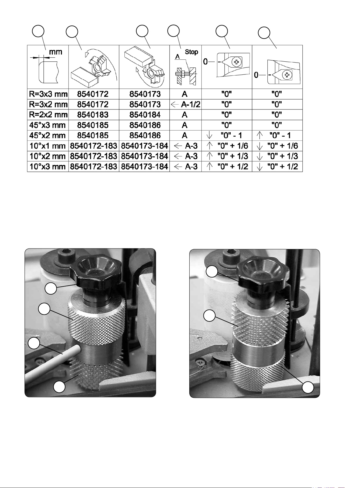
1
1. Tipo de perlador / Trim type / Type d'arasage / Art der Prolfräsung / Tipo di rilatura / Tipo de perlado / Sposób frezowania
2. Fresa superior / Upper bit / Fraise supérieure / Obere Fräse / Fresa superiore / Fresa superior / Górny frez
3. Fresa inferior / Lower bit / Fraise inférieure / Untere Fräse / Fresa inferiore / Fresa inferior / Dolny frez
4. Tope del cabezal / Head stopper / Butée tête / Anschlag des Kopfstücks / Finecorsa testa / Topo cabeçal / Pocycja zablokowania g
5. Palpador superior / Upper feeler / Palpeur supérieur / Oberer Fühler / Tastatore superiore / Apalpador superior / Wska
6. Palpador inferior / Lower feeler / Palpeur inférieur / Unterer Fühler / Tastatore inferiore / Apalpador inferior / Wska
Subir palpador / Raise feeler / Monter palpeu / Fühler heraufsetzen / Sollevare tastatore / Subir apalpador / Podnie
Bajar palpador / Lower feeler / Baisser palpeur / Fühler heruntersetzen / Abbassare tastatore / Descer apalpador / Opu
Desplazar cabezal / Move head / Déplacer tête / Kopfstück versetzen / Muovere testa / Deslocar cabeçal / Przesuń g
2
3
4
5
6
Fig.26
żnik górny
żnik dolny
ś wskażnik
ść wskażnik
łowicę
łowicy
Fig.27
D2
B2
C2
E2
Para cantos de espesor e= 1 a 3 mm.
For edges of thickness = 1 to 3 mm.
Pour une épaisseur de chant = 1 à 3 mm.
Für Kanten mit Stärke = 1 bis 3 mm.
Per bordi di spessore = 1 - 3 mm.
Para cantos com uma espessura = 1 a 3 mm.
Для кромочного материала толщиной от 1 до 3 мм.
Dla obrzeży o grubości = 1 do 3 mm.
Fig.28
D2
E2
B2
Para cantos de espesor e= 0,4 a 1 mm.
For edges of thickness = 0.4 to 1 mm.
Pour une épaisseur de chant = 0,4 à 1 mm.
Für Kanten mit Stärke = 0,4 bis 1 mm.
Per bordi di spessore = 0,4 - 1 mm.
Para cantos com uma espessura = 0,4 a 1 mm.
Для кромочного материала толщиной от 0,4 до 1 мм.
Dla obrzeży o grubości = 0,4 do 1 mm.
47
Page 48

K4
E4
J4
D4
Fig.29
Fig.30
J4
Fig.29.2
F4
Q4
J4
Fig.32
G4
H4
L4
K4
I4
Fig.31
Fig.33
48
Page 49

Fig.34
M4
Fig.35
Fig.36
Fig.37
49
Page 50

Page 51

Page 52

http://www.virutex.es/registre
Acceda a toda la información técnica.
Access to all technical information.
Accès à toute l’information technique.
Zugang zu allen technischen Daten.
Accedere a tutte le informazioni tecniche.
Aceso a todas as informações técnicas.
Dostęp do wszystkich informacji technicznych.
Доступ ко всей технической информации.
8596778 032014
Virutex, S.A.
Antoni Capmany, 1
08028 Barcelona (Spain)
www.virutex.es
 Loading...