

Page 1
Cepillo de curvas
Curved planer
Rabot cintrable
Kurvenhobel
Pialleto per curve
Plaina de contornos
Криволинейный Рубанок
MANUAL DE INSTRUCCIONES
Español (p. 2)
OPERATING INSTRUCTIONS
English (p. 4)
MODE D' EMPLOI
Français (p. 7)
GEBRAUCHSANWEISUNG
Deutsch (s. 9)
MANUALE D'ISTRUZIONI
Italiano (p. 12)
MANUAL DE INSTRUÇÕES
Portugués (p. 15)
ИНСТРУКЦИЯ ПО ЭКСПЛУАТАЦИИ
Русский
(c.
17)
CE96H
Modelo · Model · Modèle · Modell · Modello · Modelo · Модель
9696190
Page 2

2
CEPILLO DE CURVAS CE96H
(Ver imagenes pag. 20, 21, 22)
IMPORTANTE
¡ATENCIÓN! Antes de utilizar la máquina lea atentamente éste MANUAL DE INSTRUCCIONES y
el FOLLETO DE INSTRUCCIONES GENERALES
DE SEGURIDAD que se adjunta. Asegúrese de
haberlos comprendido antes de empezar a operar
con la máquina.
Conserve los dos manuales de instrucciones para
posibles consultas posteriores.
1. INSTRUCCIONES DE SEGURIDAD
PARA EL MA NE JO DEL CEPILLO
1. ¡ATENCIÓN! Lea atentamente el FO LLE TO DE INS TRUC CIO NES GE NE RA LES DE SE GU RI DAD que se
ad jun ta con la documentación de la má qui na.
2. Asegúrese antes de conectar la má qui na, que la
ten sión de alimentación corresponda con la in di ca da
en la chapa de características.
3. Mantenga siempre las manos ale ja das del área
de corte, y sujete siempre la máquina por las em pu ña du ras con las dos manos.
4. Use siempre cuchillas ori gi na les VIRUTEX. No
utilice nun ca cuchillas incorrectas, de fec tuo sas o en
mal es ta do.
5. Es necesario trabajar con aspiración de la viruta
para prolongar la vida de las cu chi llas y evitar po si bles ro tu ras.
6. Evite cortar clavos. Ins pec cio ne la su per fi cie a
trabajar antes de cepillar.
7. Esperar a que la máquina esté com ple ta men te
parada antes de soltarla o apartarla.
8. Deberían utilizarse protectores auditivos durante
el uso de la máquina (ver capítulo 11).
2. CARACTERÍSTICAS TÉCNICAS
Potencia absorbida...........................................700 W
Motor.............................................................50/60 Hz
Velocidad portacuchillas.........................16500 min
-1
Cortes por mi nu to...............................................33000
Nivel de presión acústica con ti nuo
equivalente ponderado...............................86.1 dB(A)
Nivel de potencia acústica.............................99 dB(A)
Nivel de vibraciones (mano-brazo) habitual.<2.5 m/s
2
Ancho de corte................................................80 mm
Radio cóncavo mínimo....................................450 mm
Radio convexo mínimo....................................400 mm
Profundidad de corte.......................................0-3 mm
Peso..................................................................3,2 Kg
3. EQUIPO
Equipo estándar
En el interior de la caja Ud. encontrará los ele men tos
si guien tes:
1. Cepillo CE96H equipado con cuchillas reversibles
de MD
2. Escuadra Guía lateral
3. Toma aspiración
4. Llave fi jación cuchillas
Herramientas opcionales
3599101 Soporte cuchillas reversibles
3531019 Juego cuchillas reversibles AR
3540118 Juego cuchillas reversibles MD
2031086 Juego cuchillas cóncavas AR 3 mm. Con
so por tes
ESPAÑOL Cepillo de curvas CE96H
2
ENGLISH CE96H Curved planer
4
FRANÇAIS Rabot cintrable CE96H
7
DEUTSCH Kurvenhobel CE96H
9
ITALIANO Pialletto per curve CE96H
12
PORTUGUÉS Plaina de contornos CE96H
15
РУССКИЙ
Криволинейный Рубанок СЕ96Н
17
MANUAL DE INS TRUC CIO NES
OPERATING INSTRUCTIONS
MODE D'EMPLOI
GEBRAUCHSANWEISUNG
MANUALE D'ISTRUZIONI
MANUAL DE INSTRUÇÕES
ИНСТРУКЦИЯ
ПО
ЭКСПЛУАТАЦИИ
página/page
seite/pa gi na
страница
Español
Page 3

3
2031087 Juego cuchillas cóncavas AR 3 mm.
4. DESCRIPCIÓN GENERAL
El cepillo CE96H dispone de un patín delantero y una
base trasera, de radio regulable, que les per mi ten
adaptarse a superfi cies cóncavas o con vexas para
su cepillado. El patín delantero permite ade más, la
re gu la ción de la pro fun di dad de corte, hasta 3 mm.
Dispone también de una es cua dra de guía, para el
referenciado lateral. Va equi pa do con cu chi llas recambiables de doble uso en metal duro, interruptor de
seguridad y toma para as pi ra ción de vi ru ta.
5. ESCUADRA GUÍA LATERAL
Monte la escuadra guía lateral L en su alojamiento y
sujételo con el pomo P (Fig. 1).
Es aconsejable trabajar con la escuadra guía la te ral
montada, siempre que sea posible, a fi n de garantizar
la perpendicularidad, entre la cara de la pieza y el
corte de las cu chi llas.
6. REGULACIONES
CEPILLADO DE SUPERFICIES CÓNCAVAS
Cepillado de Aproximación:
Trazar la línea de referencia R, para el cepillado de
aproxi ma ción (Fig. 2).
Colocar la profundidad de cor te a "0", mediante el
pomo C (Fig. 2).
Ajustar el patín y la base, a un radio algo menor,
que el que vamos a repasar, mediante los pomos A
y B (Fig. 2).
Dar al patín la profundidad de corte deseada, ac cio nan do el pomo C (Fig. 2).
Montar la escuadra guía la te ral, como se indica en el
apartado 5 (Fig. 1).
Proceder al cepillado de irre gu la ri da des, usando como
su per fi cie de apoyo para el comienzo de corte, la del
patín y actuando sucesivamente en las zonas con
des via cio nes, para acercarse al tra zo de re fe ren cia.
Cepillado de Acabado:
Para el cepillado de un espesor cons tan te, a lo largo
de una superfi cie cóncava, o para dar una pasada
continua de aca ba do, a la superfi cie aproximada
en el apartado anterior, pro ce de re mos del siguiente
modo:
Colocar la pasada a "0", me dian te el pomo C (Fig. 3).
Afl ojar los pomos A y B, que sujetan el patín y la base.
Situar el cepillo sobre la superfi cie a rebajar, pre sio -
nán do lo con tra ésta, de modo que el patín y la base
se adapten a ella, fi jándolos en esta po si ción, con los
pomos A y B (Fig. 3). Compruebe el paralelismo del
patín y de la base, verifi cando que señale la misma
división, sobre los ti ran tes L (Fig. 10), a ambos lados
del cepillo.
Ajustar la profundidad de cor te deseada, mediante
el pomo C (Fig. 3).
Montar la escuadra guía la te ral, como se indica en el
apartado 5 (Fig. 1).
Para el cepillado de la pieza, se usará como guía
de apoyo para el comienzo de corte, la superfi cie
del patín y al avanzar irá ampliandose el apoyo a
toda la base.
CEPILLADO DE SUPERFICIES CON VEXAS
Cepillado de aproximación:
Trazar la línea de referencia R, para el cepillado de
aproxi ma ción (Fig. 4).
Afl ojar el pomo A, colocar la profundidad de corte a
"0", mediante el pomo C y fi jar el patín de nuevo con
el pomo A, en posición horizontal (Fig. 4).
Colocar la máquina sobre la pieza acepillar. Dar a la
base un radio li gera men te mayor, que el de la pieza y
fi jarla en esa posición mediante el pomo B (Fig. 4).
Ajustar la profundidad de cor te deseada, mediante
el pomo C (Fig. 4).
Montar la escuadra guía la te ral, como se indica en el
apartado 5 (Fig. 1).
Para proceder al cepillado de irre gu la ri da des por
zonas, usaremos como su per fi cie de apoyo para
el comienzo del cepillado, el patín o la base, según
con ven ga y una vez sobre la pieza mo di fi ca re mos
li ge ra men te la po si ción del ce pi llo, para que el apoyo se
realice sobre los extremos mas próxi mos a la cuchilla,
del patín y la base, como puede verse en la (Fig. 4).
Cepillado de acabado:
Para el cepillado de un espesor cons tan te, a lo largo de
una superfi cie convexa, o para dar una pasada continua
de aca ba do, a la superfi cie aproximada en el apartado
anterior, pro ce de re mos del siguiente modo:
Colocar la pasada a "0", me dian te el pomo C (Fig. 5).
Afl ojar los pomos A y B, que sujetan el patín y la base.
Situar el cepillo sobre la superfi cie a trabajar y adap tar
el patín y la base al radio de la pieza, fi jándolos con
los pomos A y B respectivamente (Fig. 5). Com prue be
el paralelismo del patín y de la base, verifi cando que
señale la misma división, sobre los tirantes L (Fig.
10), a ambos lados del cepillo.
Ajustar la profundidad de cor te deseada, mediante
el pomo C (Fig. 5).
Montar la escuadra guía la te ral, como se indica en el
apartado 5 (Fig. 1).
Para el cepillado de la pieza, se usará como guía
de apoyo para el comienzo de corte, la superfi cie
del patín y al avanzar irá ampliandose el apoyo a
toda la base.
CEPILLADO DE SUPERFICIES PLA NAS
Afl ojar los pomos A y B (Fig. 6), para liberar el patín
de lan te ro y la base, de los tirantes de curvatura.
Poner el patín a "0", mediante el pomo C (Fig. 6).
Situar el cepillo sobre una superfi cie plana y pre-
sio nan do la parte trasera de la base, para que esta
se adapte al plano horizontal, sujetar el pomo B
(Fig. 6).
Dar la profundidad de corte deseada al patín, ac cio nan do el pomo C y fi jar el pomo A en esta posición.
(Fig. 6).
CEPILLADO CON CUCHILLAS
CÓNCAVAS (Op cio na les)
Para el acabado rústico de superfi cies a la antigua, de
Page 4

4
aspecto idéntico a un acabado con azuela.
Preparación del cepillo:
Monte las cuchillas cóncavas del modo indicado en
las fi guras 11 a la 16.
Sitúe la base y el patín de la máquina, como si fuese
a cepillar una superfi cie cóncava (Fig. 2).
Ponga el patín a su máxima profundidad de corte.
Cepillado rústico:
Para efectuar el cepillado de huellas cóncavas en la
madera, coloque el cepillo sobre ésta apoyado en el
extremo mas avanzado del patín, póngalo en marcha
y balancéelo hacia abajo. Cuando alcance el fi nal
del patín, las cuchillas empezarán a cortar madera,
mo men to en que debe detener el balanceo e iniciar
un movimiento longitudinal, que alargará la huella
del corte en la madera y proseguir a continuación
con el movimiento de balanceo hasta que la cuchilla
aban do ne el corte.
7. SUSTITUCIÓN Y REGULACIÓN
DE CU CHI LLAS RECTAS
¡ATENCIÓN! Desconecte la má qui na de la red eléc tri ca
antes de realizar estas operaciones.
SUSTITUCIÓN DE LAS CUCHILLAS
Afl ojar los tornillos D (Fig. 7), con la llave fi jación
cu chi llas y desplazar la te ral men te la cuchilla, hasta
liberarla del soporte.
Introducir una nueva cuchilla, o la misma cuchilla ex traí da, por su segunda cara de corte, en el so por te.
Comprobar con la ayuda de un regle S, que el lateral
de la cuchilla, llega al nivel del patín y la base sin
so bre pa sar los, y apretar los tornillos D (Fig. 7).
¡ATENCIÓN! Es muy importante la ve ri fi ca ción con el
regle, del lateral de la cuchilla, ya que si so bre pa sa
el nivel del patín y la base, rozaría con la escuadra
guía lateral, al usar ésta.
REGULACIÓN DE LAS CUCHILLAS
Los soportes de las cuchillas, salen re gu la dos de
fábrica y no precisan ser reajustados, al cambiar
las cuchillas. No obs tan te si por algún motivo desea
reajustarlos, proceda del si guien te modo:
Colocar el patín a "0", me dian te el pomo C (Fig. 7).
Situar un regle S entre el patín y la base y actuar
sobre los tornillos E del soporte de la cuchilla, para
elevarla o es con der la, hasta que quede per fec ta men te enrasada con el regle y paralela a la base de
la máquina (Fig. 7).
¡ATENCIÓN! Asegúrese que los tor ni llos D (Fig. 7)
estén bien apretados antes de reanudar el trabajo
con la má qui na.
Para recambios en el sistema portacuchillas, uti li zar
ex clu si va men te componentes ori gi na les VIRUTEX.
8. CAMBIO DE LA CORREA DE TRANS MI SIÓN
¡ATENCIÓN! Desconecte la má qui na de la red eléc tri ca, antes de efectuar esta ope ra ción.
Extraer la protección F, desenroscando los tornillos
G (Fig. 8). Sustituir la correa deteriorada por otra
original VIRUTEX, teniendo la pre cau ción de en-
gra nar la co rrec ta men te con los dientes de la po lea
y sin forzarla.
9. TOMA DE ASPIRACIÓN
Para el montaje de la toma de as pi ra ción, des mon tar
la guía de salida de viruta H (Fig. 9), quitando el
tornillo I y montar la toma de aspiración en el mis mo
alo ja mien to.
El cepillo puede conectarse a los Aspiradores Virutex
AS182K, AS282K directamente, o me dian te el Aco pla mien to As pi ra dor Stan dard 6446073. Mediante
este úl ti mo, pue de también co nec tar se a cualquier
as pi ra dor in dus trial.
10. MANTENIMIENTO DE
ESCOBILLAS Y CO LEC TOR
¡ATENCIÓN! Desconecte la má qui na de la red
eléc tri ca, antes de efectuar cualquier operación de
man te ni mien to.
Es importante sustituir las escobillas cuando ten gan
una longitud mínima de 5 mm. (Fig. 8).
Desenroscar los tapones de color negro J (Fig. 8), de
la carcasa y extraer la escobilla de la guía.
Sustituir, las escobillas por unas ori gi na les VIRUTEX
y com pro bar que deslizan suavemente dentro de sus
guías. Ros car nuevamente el tapón J que los en cie rra
y dejar la máquina en marcha du ran te 15 minutos.
Si el
colector presenta que ma du ras o resaltes, se re co mien da
hacerlo reparar en un ser vi cio técnico VIRUTEX.
Mantenga siempre el cable y el enchufe en buenas
con di cio nes de servicio.
11. NIVEL DE RUIDO Y VI BRA CIO NES
Las mediciones de ésta he rra mien ta eléc tri ca, han
sido efectuadas según norma Europea EN50144.
El nivel de ruidos en el puesto de trabajo, puede
so bre pa sar 85 dB(A). En este caso, es necesario
tomar me di das de protección contra el ruido para el
usuario de la he rra mien ta.
12. GARANTÍA
Todas las máquinas electroportátiles VIRUTEX, tie nen
una garantía válida de 12 meses a partir del día de
su mi nis tro, quedando ex clui das todas las ma ni pu la cio nes o da ños ocasionados por manejo in ade cua do
o por des gas te na tu ral de la máquina. Para cual quier
re pa ra ción di ri gir se al Servicio Ofi cial de Asis ten cia
Técnica VIRUTEX.
VIRUTEX se reserva el derecho de modifi car sus
pro duc tos sin previoaviso.
CE96H CURVED PLANER
(See fi gures in pages 20, 21, 22)
IMPORTANT
CAUTION. Read these OPERATING INSTRUCTIONS
English
Page 5

5
and the attached GENERAL SAFETY INSTRUCTIONS
LEAFLET carefully before using the machine. Make
sure you have understood them before operating the
machine for the fi rst time.
Keep both sets of instructions for any future queries.
1. SAFETY INSTRUCTIONS FOR
USE OF THE PLANER
1. WARNING! Read carefylly the GENERAL SAFETY
INSTRUCTIONS LEAFLET, which is included in the
machine documentation.
2. Before starting up the machine make sure that
the supply voltage is the same as that shown on the
specifi cation plate.
3. Keep hands away from the cutting area at all times
and always hold the machine down with both hands
using the handles.
4. Always use original VIRUTEX blades. Never use
incorrect, defective or faulty blades.
5. It is necessary to work with dust collection in order
to prolong the life of the blades and prevent any
breakages.
6. Avoid cutting nails. Check the work surface before
planing.
7. Wait until the machine has come to a complete stop
before putting it down or storing it.
8. Wear earplugs when using the machine (see
chapter 11)
2. TECHNICAL CHARACTERISTICS
Imput Power.....................................................700 W
Motor.............................................................50/60 Hz
No load speed.......................................16,500 min
-1
Cuts per minute.................................................33,000
Equivalent measured continuous
acoustic pressure level.............................86.1 dB (A)
Level of acoustic power...............................99 dB (A)
Usual level of vibrations (hand-arm)............<2.5 m/s
2
Cutting width.....................................................80 mm
Minimum concave radius.................................450 mm
Minimum convex radius...................................400 mm
Cutting depth....................................................0-3 mm
Weight...............................................................3.2 Kg
3. EQUIPMENT
Standard equipment
Inside the box you will fi nd the following compo-
nents:
1. Planer CE96H - set with reversible MD blades
2. Lateral fence guide
3. Dust collector connection
4. Spanner for fi xing blades
Optional tools
3599101 - Reversible blade support
3531019 - Set of reversible AR blades
3540118 - Set of reversible MD blades
2031086 - Set of 3-mm concave AR blades, with
supports
2031087 - Set of 3-mm concave AR blades
4. GENERAL DESCRIPTION
The CE96H planer is equipped with a front shoe and
a rear base with adjustable radiuses which allow
them to be adapted to convex or concave surfaces
for planing. The front shoe also permits the cutting
depth to be adjusted up to 3 mm. The planer is also
equipped with a lateral fence; double use, hard metal,
re place a ble blades; a safety switch, and a dust collector connection.
5. LATERAL FENCE
Place the lateral fence L in position and secure with
knob P (Fig. 1).
It is advisable to work with the lateral fence mount ed
when ev er possible to ensure perpendicularity between
the face of the piece and the blade cut.
6. ADJUSTMENTS
PLANING CONCAVE SURFACES
Approximation planing:
Draw a line of reference R, for approximation plan ing (Fig. 2).
Set the cut depth to "0" using knob C (Fig. 2).
Set the shoe and the base to a radius slightly lower
than the radius to be planed using knobs A and B
(Fig. 2).
Set the shoe to the desired cut depth using knob C
(Fig. 2).
Mount the lateral fence as indicated in sec tion 5
(Fig. 1).
Plane out irregularities using the shoe surface as a
support to commence cutting and move suc ces sive ly
along the areas with irregularities towards the line of
reference.
Finish planing:
To plane a concave surface with uniform thickness
or to
give a continuous fi nish to a close planed surface as
described in the previous section, pro ceed as follows:
Set the cut depth to "0" using knob C (Fig. 3).
Loosen knobs A and B which secure the shoe and the
base. Place the planer on the surface to be worked
so that the shoe and the base adapt to the surface,
and secure them in the desired position using knobs A
and B (Fig. 3). Check that the slipper and the base are
parallel, making sure that the same division is shown
over straps L (Fig. 10) on both sides of the planer.
Adjust the cut depth to the desired level using knob
C (Fig. 3).
Mount the lateral fence as indicated in sec tion 5
(Fig.1).
To plane the piece, use the shoe surface as a support
guide to commence cutting and gradually widen the
sup port to the entire base.
PLANING CONVEX SURFACES
Approximation planing:
Page 6

6
Draw a line of reference R, for approximation plan ing (Fig. 4).
Loosen knob A, set the cut depth to "0" using knob
C and secure the shoe in a horizontal position once
again using knob A (Fig. 4). Place the machine on the
piece to be planed. Give the base a slightly higher
radius than that of the piece to be planed and secure
it in position using knob B (Fig. 4).
Set the desired cut depth using knob C (Fig. 4).
Mount the lateral fence as indicated in sec tion 5
(Fig. 1).
To plane out irregularities by area, use the shoe or
base surface as a support to commence cutting. Once
on the piece, modify the plane position slightly so that
it is sup port ed on the ends of the shoe and the base,
closest to the blades as seen in (Fig. 4).
Finish planing:
To plane a convex surface with uniform thickness or
to give a continuous fi nish to a close planed surface
as described in the previous section, proceed as
follows:
Set the cut depth to "0" using knob C (Fig. 5).
Loosen knobs A and B which secure the shoe and the
base. Place the planer on the surface to be worked,
adapting the shoe and the base to the radius of the
piece, securing them in the desired position using
knobs A and B, re spec tive ly (Fig. 5). Check that slipper and the base are parallel, making sure that the
same division is shown over straps L (Fig. 10) on both
sides of the planer.
Adjust the cut depth to the desired level using knob
C (Fig. 5).
Mount the lateral fence as indicated in sec tion 5
(Fig. 1).
To plane the piece, use the shoe surface as a support
guide to commence cutting and grad u al ly widen the
sup port to the entire base.
PLANING FLAT SURFACES
Loosen knobs A and B (Fig. 6) to release the front shoe
and the base from the curvature straps.
Set the shoe to "0" using knob C (Fig. 6).
Place the planer on the fl at surface. Pressing the rear
part of the base so that it adapts to the horizontal
plane, secure knob B (Fig. 6). Set the shoe to the
desired cut depth using knob C and secure knob A in
this position (Fig. 6).
PLANING WITH CONCAVE BLADES (Optional)
To give surfaces a rustic, old-fashioned fi nish that
looks identical to an adze fi nish.
Getting the planer ready
Mount the concave blades as shown in Figures 11
to 16.
Position the base and shoe of the machine, as if you
were about to plane a concave surface (Fig. 2).
Place the shoe at its maximum cutting depth.
Rustic planing
To carry out a planing job that will leave concave
marks in the lumber, position the planer on the lumber
so that it is leaning against the front end of the shoe.
Then switch it on and swing it downwards. When it
reaches the end of the shoe, the blades will begin to
cut the lumber. At this point, stop the swinging motion
and move the planer lengthways so as to lengthen the
cutting mark in the lumber. Then start the swinging
motion once again until the blade leaves the cut.
7. REPLACING AND REGULATING
STRAIGHT BLADES
WARNING! Disconnect the machine from the pow er
source before performing the following op er a tions.
REPLACING BLADES
Loosen screws D (Fig. 7) with the blade securing key and
move the blade laterally to free it from the support.
Place a new blade into the support or use the second
cutting edge of the blade just ex tract ed.
With the help of a ruler, S, confi rm that the side of
the blade
reaches the level of the shoe and the base without
pro trud ing and tighten the screws D (Fig. 7).
WARNING! It is very important to verify the side of the
blade with the ruler; if it exceeds the level of the shoe
or the base, it will rub against the lateral fence when
the square is being used.
ADJUSTING BLADES
The blade supports are already adjusted from the factory and do not require readjustment when the blades
are changed. How ev er, if you wish to readjust them,
proceed as follows:
Set the shoe to "0" using knob C (Fig. 7).
Place a ruler S, between the shoe and the base and
loosen screws E of the blade support to lift or lower
the blade until it is perfectly even with the ruler and
parallel to the base of the machine (Fig. 7).
WARNING! Ensure that screws D (Fig. 7) are correctly
tightened before resuming work with the machine.
For blade-holder system spares use only original
VIRUTEX components.
8. CHANGING THE TRANSMISSION BELT
WARNING! Disconnect the machine from the pow er
source before performing the following op er a tion.
Unscrew screws G (Fig. 8) and remove protection F.
Replace the worn belt with a VIRUTEX original spare, taking care to fi t it correctly into the pulley teeth,
never forcing it.
9. DUST COLLECTOR CONNECTION
To assemble the dust collector connection, detach the
shav ing outlet guide H (Fig. 9) by removing screw I
and insert the dust collector connection in the same
opening.
The planer may be connected to the Virutex Vacuum
cleaner AS182K, AS282K either directly or by means of
a dust col lec tor attachment 6446073. This at tach ment
may also be used to connect the planer to any industrial
sawdust collector.
Page 7

7
10. MAINTENANCE OF THE
BRUSHES AND COLLECTOR
WARNING! Disconnect from the mains before carrying
out any maintenance operations.
The brushes must be replaced when they reach a
minimum length of 5 mm (Fig. 8).
Unscrew the black caps J (Fig. 8) on the housing and
remove the brushes from the guide. Replace them with
new VIRUTEX original spares, ensuring that they move
smoothly inside the guides. Screw on the cap J which
covers them and leave the machine running for 15
minutes. If the collector is burned or uneven it should
be repaired by a VIRUTEX service agent.
Always keep the lead and plug in good working
condition.
11. NOISE LEVEL AND VIBRATIONS
These levels have been measured according to the
European Standard EN50144. The noise level in the
workplace could go over 85 dB(A). In this case it is
necessary for the user to wear noise protection.
12. WARRANTY
All VIRUTEX power tools are guaranteed for 12 months
from the date of purchase, excluding any damage which
is a result of incorrect use or of natural wear and tear
on the machine. All repairs should be carried out by the
offi cial VIRUTEX technical assistance service.
VIRUTEX reserves the right to modify its products
without prior notice.
RABOT CINTRABLE CE96H
(Voir images p. 20, 21, 22)
IMPORTANT
ATTENTION! Avant d'utiliser la machine, lisez attentivement ce MANUEL D'INSTRUCTIONS et la
BROCHURE D'INSTRUCTIONS GÉNÉRALES DE
SÉCURITÉ qui vous sont fournis avec cette machine.
Assurez-vous de bien avoir tout compris avant de
commencer à travailler sur la machine.
Gardez toujours ces deux manuels d'instructions à
portée de la main pour pouvoir les consulter, en cas
de besoin.
1. INSTRUCTIONS DE SÉCURITÉ POUR
L'UTILISATION DU RABOT
1. ATTENTION! Lire attentivement la BROCHURE
D'INSTRUCTIONS GÉNÉRALES DE SÉCURITÉ
jointe à la documentation de la machine.
2. Avant de brancher la machine, vérifi er si la tension
d'alimentation correspond à celle indiquée sur la plaque
des caractéristiques.
3. Toujours tenir les mains à bonne distance des lames
et saisir à deux mains la machine par ses poignées.
4. Utiliser uniquement des couteaux d'origine VI-
RUTEX. Ne jamais utiliser de lames inadéquates,
défectueuses ou en mauvais état.
5. Il faut travailler avec un aspirateur de copeaux pour
prolonger la durée de vie des couteaux et éviter des
cassures éventuelles.
6. Éviter de couper des clous. Vérifi er la surface à
travailler avant de rabotter.
7. Attendre que la machine soit complètement arrêtée
avant de la lâcher ou de la ranger.
8. Il faut utiliser des protections auditives quand on
utilise la machine (voir chapitre 11).
2. CARACTÉRISTIQUES TECHNIQUES
Puissance absorbée........................................700 W
Moteur...........................................................50/60 Hz
Vitesse porte-couteaux........................16.500 min
-1
Coupes par minute...........................................33.000
Niveau de pression acoustique
continu équivalent pondéré......................86,1 dB (A)
Niveau de puissance acoustique.................99 dB (A)
Niveau de vibrations (main-bras) habituel...<2,5 m/s
2
Largeur de coupe..............................................80 mm
Rayon concave minimum................................450 mm
Rayon convexe minimum................................400 mm
Profondeur de coupe........................................0-3 mm
Profondeur de feuillure......................................11 mm
Poids.................................................................3,2 Kg
3. ÉQUIPEMENT
Équipement standard
À l'intérieur de la mallette, se trouvent les éléments
suivants :
1. Rabot CE96H équipé de couteaux réversibles
de MD
2. Équerre de guidage latéral
3. Prise d'aspiration
4. Clé de fi xation des couteaux
Outils optionnels
3599101 Support couteaux réversibles
3531019 Jeu couteaux réversibles AR
3540118 Jeu couteaux réversibles MD
2031086 Jeu couteaux concaves AR 3 mm. Avec
supports
2031087 Jeu couteaux concaves AR 3 mm.
4. DESCRIPTION GÉNÉRALE
Le rabot CE96H est pourvu d'un patin frontal et d'une
base arrière, dont le rayon peut être réglé, qui lui permettent d'épouser les surfaces concaves et convexes
à raboter. Le patin avant permet en outre de régler la
profondeur de feuillure, jusqu'à 3 mm. Il est également
équipé d'une Équerre de Guidage pour le repérage
latéral, ainsi que de lames double usage remplaçables
en métal dur, d'un interrupteur de sécurité et d'une
prise d'aspiration de sciure.
5. ÉQUERRE GUIDE LATÉRAL
Montez l'équerre guide latérale L dans son logement
et fi xez-la avec le pommeau P (Fig. 1).
Français
Page 8

8
Il vaut mieux n'utiliser l'appareil qu'après avoir monté
l'équerre guide latérale, afi n que la face de la pièce
et les fers de rabotage soient parfaitement perpendiculaires.
6. RÉGLAGES
RABOTAGE DES SURFACES CONCAVES
Rabotage d'approche:
Tracer la ligne de référence R avant de commencer
le rabotage d'approche (Fig. 2).
Régler la profondeur de feuillure sur "0" avec le
pommeau C (Fig. 2).
À l'aide des pommeaux A et B (Fig. 2), régler le patin
et la base sur un rayon légèrement plus court que
celui de la pièce à raboter.
Régler le patin à la profondeur de feuillure désirée en
actionnant le pommeau C (Fig. 2).
Monter l'équerre guide latérale tel qu'indiqué au
paragraphe 5 (Fig. 1).
Commencer à raboter les irrégularités en utilisant
le patin comme surface d'appui; raboter peu à peu
toutes les zones irrégulières pour s'approcher du
trait de référence.
Rabotage de fi nition:
Pour raboter à épaisseur constante le long d'une
surface concave, ou pour terminer de polir la surface
ébauchée (paragraphe précédent), procéder de la
façon suivante:
Régler la profondeur de feuillure sur "0" à l'aide du
pommeau C (Fig. 3).
Desserrer les pommeaux A et B, qui retiennent le patin
et la base. Placer le rabot sur la surface à aplanir,
en exerçant une pression contre elle de façon à ce
que le patin et la base en épousent la forme; les fi xer
dans cette position à l'aide de pommeaux A et B (Fig.
3). Vérifi er le parallélisme du patin et de la base, en
s'assurant que la même division est marquée sur les
tirants L (Fig. 10) de chaque côté de la rabot.
Régler la profondeur de feuillure à l'aide du pommeau
C (Fig. 3).
Monter l'équerre guide latérale comme indiqué au
paragraphe 5 (Fig. 1).
Pour commencer à raboter la pièce, utiliser la surface
du fer comme guide d'appui, puis élargir l'appui à
toute la base.
RABOTAGE DE SURFACES CONVEXES
Rabotage d'approche:
Tracer la ligne de référence R avant de commencer
le rabotage d'approche (Fig. 4).
Desserrer le pommeau A, régler la profondeur de
feuillure sur "0" à l'aide du pommeau C et fi xer de
nouveau le patin en position horizontale à l'aide du
pommeau A (Fig. 4).
Placer la machine sur la pièce à raboter. Régler la
base en fonction d'un rayon légèrement supérieur
que celui de la pièce, puis la fi xer dans cette position
à l'aide du pommeau B (Fig. 4).
Régler la profondeur de feuillure à l'aide du pommeau
C (Fig. 4).
Monter l'équerre guide latérale comme indiqué au
paragraphe 5 (Fig. 1).
Pour raboter les irrégularités zone par zone, commencer l'opération en utilisant le patin ou la base
comme surface d'appui, puis modifi er légèrement la
position du rabot pour que l'appui se déplace vers les
extrémités les plus proches de la lame, du patin et
de la base (Fig. 4).
Rabotage de fi nition:
Pour raboter à épaisseur constante le long d'une
surface convexe, ou pour terminer de polir la surface
ébauchée (paragraphe précédent), procéder de la
façon suivante:
Régler la profondeur de feuillure sur "0" à l'aide du
pommeau C (Fig. 5).
Desserrer les pommeaux A et B, qui retiennent le patin
et la base. Placer le rabot sur la surface à aplanir,
adapter le patin et la base au rayon de la pièce, puis
les fi xer dans cette position à l'aide de pommeaux A et
B (Fig. 5). Vérifi er le parallélisme du patin et de la base,
en s'assurant que la même division est marquée sur
les tirants L (Fig. 10) de chaque côté de la rabot.
Régler la profondeur de feuillure désirée à l'aide du
pommeau C (Fig. 5).
Monter l'équerre guide latérale comme indiqué au
paragraphe 5 (Fig. 1). Pour commencer à raboter la
pièce, utiliser la surface du patin comme guide d'appui,
puis élargir l'appui à toute la base.
RABOTAGE DE SURFACES PLANES
Desserrer les pommeaux A et B (Fig. 6) pour libérer le
fer avant et la base des entretoises de courbure.
Régler le patin sur "0" à l'aide du pommeau C (Fig.
6).
Placer le rabot sur une surface plane et appuyer sur
l'arrière de la base afi n qu'il épouse le plan horizontal;
serrer le pommeau B (Fig. 6). À l'aide du pommeau C,
régler le patin à la profondeur de feuillure désirée et
fi xer le pommeau A dans cette position (Fig. 6).
RABOTAGE AVEC DES COUTEAUX
CONCAVES (Optionnels)
Pour la fi nition rustique de surfaces à l'ancienne,
donnant un aspect identique à une fi nition à l'her-
minette.
Préparation du Rabot:
Monter les couteaux concaves comme cela est indiqué
sur les fi gures 11 à 16.
Placer la base et le patin de la machine comme pour
raboter une surface concave (Fig. 2).
Régler le patin sur sa profondeur de coupe maximale.
Rabotage rustique:
Pour faire le rabotage à empreintes concaves sur le
bois, placer le rabot sur celui-ci appuyé sur l'extrémité
la plus avancée du patin, le mettre en marche et le
balancer vers le bas. En arrivant à la fi n du patin, les
couteaux commenceront à couper le bois, il faut alors
arrêter le balancement et commencer un mouvement
longitudinal, qui allongera l'empreinte de la coupe sur
Page 9

9
le bois, et continuer ensuite le mouvement de balancement jusqu'à ce que le couteau arrête de couper.
7. REMPLACEMENT ET RÉGLAGE
DE COUTEAUX DROITS
ATTENTION! Débrancher la machine du secteur avant
d'effectuer ces opérations.
REMPLACEMENT DES LAMES
Desserrer les vis D (Fig. 7) avec la clé de fi xation des
lames, puis pousser la lame sur le côté jusqu'à ce
qu'elle se dégage du support.
Placer une nouvelle lame sur le support, ou retourner
la lame usée pour en utiliser l'autre tranchant.
Vérifi er à l'aide d'une règle S que le bord de la lame
est à niveau avec le patin et la base, resserrer les
vis D (Fig.7).
ATTENTION! Cette vérifi cation à la règle est très
importante: si la lame dépasse du patin et de la base,
elle frottera contre l'équerre guide latérale.
RÉGLAGE DES LAMES
Les supports des lames étant pré-réglés en usine,
il est inutile de les réajuster lorsqu'on remplace
les lames. Cependant, en cas de besoin, procéder
comme suit:
Régler le patin sur "0" à l'aide du pommeau C (Fig.
7).
Placer une règle S entre le patin et la base et faire jouer
les vis E du support pour élever la lame ou la cacher
jusqu'à ce qu'elle soit parfaitement en ligne avec la
règle et parallèle à la base de la machine (Fig.7).
ATTENTION! Vérifi er si les vis D (Fig. 7) sont bien se-
rrées avant de reprendre le travail avec la machine.
Pour les pièces de rechange dans le porte-couteaux,
utiliser exclusivement des composants d'origine
VIRUTEX.
8. CHANGEMENT DE LA
COURROIE DE TRANSMISSION
ATTENTION! Débrancher la machine du secteur avant
d'effectuer cette opération.
Extraire la protection F en dévissant les vis G (Fig.
8). Remplacer la courroie abîmée par une d'origine
VIRUTEX en faisant en sorte de bien l'engrener sur
les dents de la poulie, sans la forcer.
9. PRISE D'ASPIRATION
Pour monter la prise d'aspiration dans son logement,
desserrer la vis I, puis démonter le guide de sortie de
la sciure H (Fig. 9).
Le rabot peut être branché directement sur l'aspirateur Virutex AS182K, AS282K, ou à l'aide de la
buse standard 6446073. Avec cette buse, on peut
également l'accoupler à n'importe quel type d'aspirateur industriel.
10. ENTRETIEN DES BALAIS
ET DU COLLECTEUR
ATTENTION! Débrancher la machine du secteur, avant
de faire toute opération d'entretien.
Il est important de changer les balais quand ils ont
une longueur minimum de 5 mm (Fig. 8).
Dévisser le bouchon noir J (Fig. 8) de la carcasse et
extraire le balai du guidage. Remplacer les balais par
des balais d'origine VIRUTEX et vérifi er s'ils glissent
doucement dans leurs guidages. Revisser le bouchon
J et laisser la machine en marche pendant 15 min. Si
le collecteur présente des brûlures ou des ressauts,
il est recommandé de le faire réparer par un service
technique VIRUTEX.
Toujours conserver le câble et la prise dans de bonnes
conditions de service.
11. NIVEAU DE BRUITS ET VIBRATIONS
Les mesures de cet outil ont été effectuées selon la
Norme Européenne EN50144. Le niveau de bruits sur
le poste de travail peut dépasser 85 dB(A). Dans ce
cas, l'usager de l'outil doit prendre des mesures de
protection contre le bruit.
12. GARANTIE
Tous les machines électro-portatives VIRUTEX ont
une garantie valable 12 mois à partir de la date
d'achat, en étant exclus toutes manipulations ou
dommages causés par des maniements inadéquats
ou par l'usure naturelle de la machine. Pour toute
réparation, s'adresser au service offi ciel d'assistance
technique VIRUTEX.
VIRUTEX se réserve le droit de modifi er ses produits
sans avis préalable.
KURVENHOBEL CE96H
(SIEHE ABB. SEITE 20, 21, 22)
ACHTUNG!
Wichtiger Hinweis: Lesen Sie bitte vor Benutzung der
Maschine die beiliegende GEBRAUCHSANWEISUNG
und die ALLGEMEINEN SICHERHEITSHINWEISE
sorgfältig durch.
Stellen Sie sicher, dass Sie sowohl die Gebrauchsanweisung als auch die allegemeinen Sicherheitshinweise verstanden haben, bevor Sie die Maschine
bedienen. Bewahren Sie beide Gebrauchsanweisungen zum späteren Nachschlagen auf.
1. SICHERHEITSHINWEISE FÜR DIE
ARBEIT MIT DEM HOBEL
1. ACHTUNG! Lesen Sie die BROSCHÜRE MIT
ALLGEMEINEN SICHERHEITSHINWEISEN, die
den Unterlagen zur Maschine beiliegt, aufmerksam
durch.
2. Versichern Sie sich, daß die Spannung der auf dem
Typenschild angegebenen entspricht, bevor Sie die
Maschine an das Netz anschließen.
3. Die Hände nicht in die Nähe des Schneidbereichs
bringen und die Maschine stets mit beiden Händen
Deutsch
Page 10

10
an den Griffen halten.
4. Verwenden Sie immer Original-VIRUTEX-Hobelmesser. Niemals unsachgemäße, beschädigte oder in
schlechtem Zustand befi ndliche Messer verwenden.
5. Bei der Arbeit ist eine Spanabsaugung notwendig,
um die Lebensdauer der Hobelmesser zu verlängern
und damit sie nicht zerbrechen.
6. Vermeiden Sie den Kontakt mit Nägeln. Sehen
Sie sich die zu bearbeitende Fläche vor dem Hobeln
genau an.
7. Warten Sie ab, bis die Maschine ganz steht, bevor
Sie sie loslassen oder wegstellen.
8. Während des Arbeitens mit der Maschine ist Gehörschutz zu tragen (siehe Kapitel 11)
2. TECHNISCHE DATEN
Leistungsaufnahme...........................................700 W
Motor.............................................................50/60 Hz
Messerhaltergeschwindigkeit................16.500 min
-1
Schnitte pro Minute............................................33000
Ungerechnetes akustisches
Dauerdruckpegeläquivalent........................86,1 dB(A)
Akustischer Leistungspegel..........................99 dB (A)
Übliches Schwingungsniveau (hand-Arm)..<2,5 m/s
2
Schnittbreite.....................................................80 mm
Konkav-Radius mindestens............................450 mm
Konvex-Radius mindestens............................400 mm
Schnittiefe........................................................0-3 mm
Gewicht.............................................................3,2 Kg
3. AUSSTATTUNG
Standardausstattung
In der Packung befi nden sich folgende Bestandteile:
1. Hobel CE96H ausgestattet mit MD-Wendemessern
2. Seitlicher Führungswinkel
3. Absauganschluss
4. Schlüssel zur Befestigung der Messer
Extra-Zubehör
3599101 Halterung für Wendemesser
3531019 AR-Wendemesser-Set
3540118 MD-Wendemesser-Set
2031086 Set konkaver AR-Messer 3 mm. Mit Halterungen.
2031087 Set konkaver AR-Messer 3 mm.
4. ALLGEMEINE BESCHREIBUNG
Der Hobel CE96H verfügt über einen Vorderschlitten
und ein hinteres Unterteil mit einstellbarem Radius,
wodurch er in der Lage ist, sich beim Hobeln an
nach innen oder nach außen gewölbte Oberfl ächen
anzupassen. Der Vorderschlitten ermöglicht zudem
die Einstellung der Schnittiefe bis zu 3 mm. Er verfügt
außerdem über einen Führungswinkel für die Arbeit
mit Seitenanschlägen. Der Hobel verfügt über auswechselbare zweischneidige Messer aus Hartmetall,
einen Sicherheitsschalter und einen Anschluß für die
Späneabsaugung.
5. SEITLICHER FÜHRUNGSWINKEL
Den seitlichen Führungswinkel L in seine Aufnahme
einsetzen und mit Knauf P befestigen (Abb. 1).
Es empfi ehlt sich, nach Möglichkeit immer mit montier-
tem seitlichem Führungswinkel zu arbeiten, um den
korrekten Winkel zwischen der Werkstückoberfl äche
und den Messern zu gewährleisten.
6. EINSTELLUNGEN HOBELN VON NACH INNEN
GEWÖLBTEN OBERFLÄCHEN
Vorhobeln:
Für das Vorhobeln die Bezugslinie R ziehen (Abb.
2).
Mit dem Knauf C die Schnittiefe "0" einstellen
(Abb.2).
Den Schlitten und das Unterteil mit den Knäufen A und
B auf einen Radius einstellen, der etwas geringer als
der zu hobelnde Radius ist (Abb. 2).
Mit dem Knauf C am Schlitten die gewünschte Schnittiefe einstellen (Abb. 2).
Den seitlichen Führungswinkel gemäß Abschnitt 5
(Abb. 1) montieren.
Unregelmäßigkeiten weghobeln; dabei als Aufl agefl ä-
che für den Schnittbeginn die Aufl age des Schlittens
nutzen. Nach und nach in allen Bereichen die Abweichungen bearbeiten, um allmählich die Bezugslinie
zu erreichen.
Fertighobeln:
Um ein Hobeln mit gleichbleibender Stärke an einer
nach innen gewölbten Oberfl äche bzw. um ein abschlie-
ßendes Hobeln auf der gemäß dem vorangegangenen
Abschnitt vorbereiteten Oberfl äche durchzuführen, ist
folgendermaßen vorzugehen:
Mit dem Knauf C die Schnittiefe auf "0" einstellen
(Abb.3).
Die Knäufe A und B, mit denen Schlitten und Unterteil
gehalten werden, lockern. Den Hobel auf die zu bearbeitende Oberfl äche aufsetzen und andrücken, so daß
sich Schlitten und Unterteil der Oberfl äche anpassen;
anschließend in dieser Position mit den Knäufen A
und B arretieren (Abb. 3). Vergewissern Sie sich, daß
sich der Gerätegleitschuh und das Unterteil parallel
zueinander befi nden und überprüfen Sie, daß auf den
Streben L (Abb. 10) auf beiden Seiten der Bürste die
selbe Einteilung angezeigt wird.
Mit dem Knauf C die gewünschte Schnittiefe einstellen
(Abb. 3).
Den seitlichen Führungswinkel gemäß Abschnitt 5
(Abb. 1) montieren.
Beim Hobeln des Werkstücks wird die Oberfl äche des
Schlittens als Aufl ageführung für den Schnittbeginn
genutzt, und bei Vorschub wird die Aufl age dann auf
die gesamte Grundfl äche ausgeweitet.
HOBELN NACH AUSSEN
GEWÖLBTER OBERFLÄCHEN
Vorhobeln:
Für das Vorhobeln die Bezugslinie R ziehen (Abb. 4).
Knauf A lockern, mit Knauf C die Schnittiefe "0" einstellen und dann den Schlitten erneut mit dem Knauf
Page 11

11
A in waagerechter Lage feststellen (Abb. 4).
Die Maschine auf das zu hobelnde Werkstück aufsetzen.
Das Unterteil auf einen Radius einstellen, der etwas
geringer als der des Werkstücks ist, und dann mit
Knauf B in dieser Lage feststellen (Abb. 4).
Mit dem Knauf C die gewünschte Schnittiefe einstellen
(Abb. 4).
Den seitlichen Führungswinkel gemäß Abschnitt 5
(Abb. 1) montieren.
Beim Weghobeln der Unregelmäßigkeiten in den
verschiedenen Bereichen wird der Schlitten oder
das Unterteil als Aufl agefl äche für den Schnittbeginn
genutzt; auf dem Werkstück wird dann die Stellung
des Hobels leicht geändert, damit die Aufl age an den
Enden erfolgt, die dem Messer von Schlitten und
Unterteil am nächsten liegen (siehe Abb. 4).
Fertighobeln:
Um ein Hobeln mit gleichbleibender Stärke an einer
nach außen gewölbten Oberfl äche bzw. um ein
abschließendes Hobeln auf der gemäß dem vorangegangenen Abschnitt vorbereiteten Oberfl äche
durchzuführen, ist folgendermaßen vorzugehen:
Mit dem Knauf C die Schnittiefe auf "0" einstellen
(Abb.5).
Die Knäufe A und B, mit denen Schlitten und Unterteil gehalten werden, lockern. Den Hobel auf die zu
bearbeitende Oberfl äche aufsetzen und andrücken,
so daß sich Schlitten und Unterteil an den Radius
des Werkstücks anpassen; anschließend in dieser
Position mit den Knäufen A und B arretieren (Abb. 5).
Vergewissern Sie sich, daß sich der Gerätegleitschuh
und das Unterteil parallel zueinander befi nden und
überprüfen Sie, daß auf den Streben L (Abb. 10)
auf beiden Seiten der Bürste die selbe Einteilung
angezeigt wird.
Mit dem Knauf C die gewünschte Schnittiefe einstellen
(Abb. 5).
Den seitlichen Führungswinkel gemäß Abschnitt 5
(Abb. 1) montieren.
Beim Hobeln des Werkstücks wird die Oberfl äche des
Schlittens als Aufl ageführung für den Schnittbeginn
genutzt, und beim Vorschub wird die Aufl age dann
auf das gesamte Unterteil ausgeweitet.
HOBELN GERADER WERKSTÜCKE
Die Knaufe A und B (Abb. 6) lockern, um den Schlitten
und das Unterteil von den Kurvenzügen zu befreien.
Den Schlitten mit dem Knauf C auf "0" stellen (Abb.
6).
Den Hobel auf eine ebene Fläche aufsetzen und den
hinteren Teil des Unterteils andrücken, damit er sich
an die ebene Arbeitsfl äche anpaßt; anschließend in
dieser Position mit Knauf B arretieren (Abb. 6).
Mit dem Knauf C die gewünschte Schnittiefe einstellen
und Knauf A in dieser Stellung arretieren (Abb. 6).
HOBELN MIT KONKAVEN
MESSERN (EXTRA-ZUBEHÖR)
Für ein rustikales Aussehen der Oberfl äche, wie mit
dem Dachsbeil bearbeitet.
Vorbereitung des Hobels
Die konkaven Messer, wie in Abbildung 11 - 16 beschrieben, montieren.
Die Aufl agefl äche des Hobels sowie den Gerätegleit-
schuh so platzieren, als würde man eine konkave
Oberfl äche bearbeiten (Abb. 2).
Den Gerätegleitschuh auf die höchste Schnitttiefe
einstellen.
Erzielen einer rustikalen Oberfl äche
Um im Holz konkave Hobelmarkierungen zu erzielen, den Hobel, gestützt auf das äußerste Ende des
Gerätegleitschuhs, auf das Holzstück stellen. Hobel
anschalten und mit einer Schwingbewegung nach
unten führen. Wird das Ende des Gerätegleitschuhs erreicht, beginnen die Messer das Holz zu schneiden. In
diesem Moment sollte die Schwingbewegung gestoppt
und mit einer Längsbewegung, die die Schnittfl äche
im Holz verlängert, begonnen werden. Dann mit der
Gleitbewegung fortfahren, bis die Messer aus dem
Holz kommen.
7. ERSETZEN UND REGULIEREN
GERADER MESSER
ACHTUNG! Vor Beginn dieser Arbeiten Netzstecker
ziehen.
AUSTAUSCHEN DER MESSER
Die Schrauben D (Abb. 7) mit dem Messerfeststellschlüssel lockern und das Messer seitlich verschieben,
bis es aus der Halterung austritt.
Ein neues Messer bzw. das eben entnommene
Messer mit der zweiten Schneide in die Halterung
einsetzen.
Mit Hilfe eines Lineals S überprüfen, daß das Seitenteil des Messers an den Schlitten und das Unterteil
heranreicht, aber nicht darüberhinausragt, und die
Schrauben D anziehen (Abb. 7).
ACHTUNG! Die Prüfung des Seitenteils des Messers
mit Hilfe des Lineals ist sehr wichtig, denn wenn das
Messer über den Schlitten und das Unterteil hinausragt,
streift es den seitlichen Führungswinkel, wenn dieser
zum Einsatz kommt.
EINSTELLUNG DER MESSER
Die Messerhalterungen sind werkseitig voreingestellt
und müssen auch beim Wechseln der Messer nicht
nachgestellt werden. Wenn es dennoch erforderlich
werden sollte, eine Nachstellung vorzunehmen, gehen
Sie bitte folgendermaßen vor:
Den Schlitten mit dem Knauf auf "0" stellen (Abb.
7).
Ein Lineal S zwischen den Schlitten und das Unterteil
bringen und die Schrauben E der Messerhalterung
verstellen, um sie anzuheben bzw. abzusenken, bis
sie genau mit dem Lineal übereinstimmt und parallel
zur Grundplatte der Maschine steht (Abb. 7).
ACHTUNG! Versichern Sie sich, daß die Schrauben
D (Abb. 7) richtig festgezogen wurden, bevor Sie
die Arbeit mit der Maschine wieder aufnehmen. Für
das Messerhaltersystem nur Originalersatzteile von
Page 12

12
VIRUTEX verwenden.
8. AUSWECHSELN DES ANTRIEBSRIEMENS
ACHTUNG! Vor Beginn dieser Arbeiten Netzstecker
ziehen.
Die Schrauben G abdrehen, um die Schutzvorrichtung
F abnehmen zu können (Abb. 8). Den beschädigten
Riemen durch ein Original-VIRUTEX-Ersatzteil ersetzen und dabei aufpassen, daß der neue Riemen
richtig in die Zähne der Riemenscheibe greift ohne
ihn in seine Position zwingen zu müssen.
9. ABSAUGANSCHLUSS
Zur Montage des Absauganschlusses muß zunächst
nach Lösen der Schraube I die Spanaustrittsführung
H (Abb. 9) abgenommen werden, um dann an der
gleichen Stelle den Absauganschluß anzubauen.
Der Hobel kann an den Absauger Virutex AS182K,
AS282K entweder direkt oder mittels der Saugerstandardkupplung 6446073 angeschlossen werden. Die
Kupplung erlaubt außerdem den Abschluß beliebiger
anderer Industriesabsauger.
10. WARTUNG VON BÜRSTEN
UND SCHLEIFRING
ACHTUNG! Vor allen Wartungsarbeiten den Netzstecker ziehen.
Die Bürsten müssen ersetzt werden, enn sie eine
Mindestlänge von 5 mm haben. (Abb. 8)
Den schwarzen Stopfen J (Abb. 8) vom Gehäuse abschrauben und die Bürste aus der Führung nehmen. Die
Bürsten durch Original-VIRUTEX- Ersatzteile ersetzen
und überprüfen, daß sie sanft in ihren Führungen gleiten. Den Stopfen J wieder anbringen und festdrehen,
und die Maschine ca. 15 Minuten laufen lassen. Wenn
der Schleifring Brandspuren oder abgesprungene
Stellen aufweist empfehlen wir, ihn vom VIRUTEXKundendienst reparieren zu lassen.
Sorgen Sie immer dafür, daß Kabel und Stecker in
einem guten, funktionsfähigen Zustand sind.
11. GERÄUSCHPEGEL
UND SCHWINGUNGSNIVEAU
Die Messungen an diesem Werkzeug wurden nach
der europäischen Norm EN50144. Der Geräuschpegel
am Arbeitsplatz kann über 85 dB(A) liegen. In diesem
Fall sind für den Benutzer des Werkzeugs Lämschutzmaßnahmen zu treffen.
12. GARANTIE
Alle Elektrowerkzeuge von VIRUTEX habe eine garantie von 12 Monaten ab dem Lieferdatum. Hiervon
ausgeschlossen sind alle Eingriffe oder Schäden
aufgrund von unsachgemässen Gebrauch oder natürlicher Abnutzung des Geräts.
Weenden Sie sich im Falle einer Reparatur immer an
den zugelassenen Kundendiest von VIRUTEX.
VIRUTEX behält sich das Recht vor, die Produkte
ohne vorherige Ankündigung zu verändern.
PIALLETO PER CURVE CE96H
(VEDERE FIGURE A PAG. 20, 21, 22)
IMPORTANTE
ATTENZIONE! Prima di utilizzare la macchina, leggere
attentamente questo MANUALE DI ISTRUZIONI e
il PROSPETTO DELLE NORME GENERALI DI SICUREZZA allegato. Non cominciate a lavorare con
la macchina se non siete sicuri di avere compreso
integralmente il loro contenuto.
Conservare tutti e due i manuali per eventuali
consultazioni successive.
1. ISTRUZIONI DI SICUREZZA
PER L'USO DEL PIALLETO
1. ATTENZIONE! Leggere attentamente l'OPUSCOLO
DI ISTRUZIONI GENERALI DI SICUREZZA allegato
alla documentazione della macchina.
2. Verifi care, prima di collegare la macchina alla rete
elettrica, che la tensione di alimentazione corrisponda
a quella indicata nella targhetta delle caratteristiche.
3. Mantenere le mani sempre lontane dall'area di taglio
e tenere sempre la macchina per le impugnature con
entrambe le mani.
4. Usare sempre coltelli originali VIRUTEX. Non utilizzare mai lame inadatte, difettose o in cattivo stato.
5. Per prolungare la vita deli coltelli ed evitare eventuali
rotture, bisognerà lavorare sempre con l'aspirazione
inserita.
6. Attenzione ai chiodi: prima di piallare, esaminare
la superfi cie su cui bisogna lavorare.
7. Attendere che la macchina si sia fermata com ple ta men te prima di allentare la presa o di separarla dalla
superfi cie di lavoro.
8. Durante l'uso della macchina è conveniente usare
protezioni per l'udito (vedere capitolo 11)
2. CARATTERISTICHE TECNICHE
Potenza assorbita............................................700 W
Motore...........................................................50/60 Hz
Velocità portacoltelli..............................16.500 min
-1
Tagli al mi nu to...................................................33.000
Livello di pressione acustica
continuo equivalente ponderato...............86,1 dB (A)
Livello di potenza acustica..........................99 dB (A)
Livello di vibrazioni
(mano-braccio) abituale.............................<2,5 m/s
2
Larghezza del taglio...........................................80 mm
Raggio concavo minimo..................................450 mm
Raggio convesso minimo................................400 mm
Profondità del taglio..........................................0-3 mm
Peso..................................................................3,2 Kg
3. DOTAZIONE
Dotazione standard
All'interno della scatola troverete i seguenti elementi:
Italiano
Page 13

13
1. Pialletto CE96H dotato di coltelli reversibili di MD
2. Squadra guida laterale
3. Attacco per aspirazione
4. Chiave per fi ssaggio coltelli
Accessori a richiesta
3599101 Supporto coltelli reversibili
3531019 Set coltelli reversibili AR
3540118 Set coltelli reversibili MD
2031086 Set coltelli concavi AR 3 mm. Con supporti
2031087 Set coltelli concavi AR 3 mm
4. DESCRIZIONE GENERALE
Il pialletto CE96H dispone di un pattino anteriore
e di una base posteriore, a raggio regolabile, che
gli permettono di adeguarsi a superfi ci concave o
convesse per procedere alla loro piallatura. Il pattino
anteriore permette, inoltre, la regolazione della profondità di taglio, sino a 3 mm. Dispone anche di una
squadra guida per il rilevamento di punti di riferimento
laterali. È dotato di lame intercambiabili a doppio uso
in metallo duro, interruttore di sicurezza e presa per
aspirazione di trucioli.
5. SQUADRA GUIDA LATERALE
Montare la Squadra Guida Laterale L nel suo alloggiamento e fi ssarla con il pomello P (Fig. 1).
Se possibile, è consigliabile lavorare sempre con la
Squadra Guida Laterale montata, al fi ne di garantire
la perpendicolarità tra la superfi cie del pezzo ed il
taglio delle lame.
6. REGOLAZIONI PIALLATURA
DI SUPERFICI CONCAVE
Piallatura di approssimazione:
Per la piallatura di approssimazione, tracciare la linea
di riferimento R (Fig. 2).
Mediante il pomello C, regolare la profondità di taglio
a "0" (zero) (Fig. 2).
Mediante i pomelli A e B, regolare il pattino e la base
su un raggio leggermente inferiore di quello che si
ripasserà (Fig. 2).
Dare al pattino la profondità di taglio desiderata,
azionando il pomello C (Fig. 2).
Montare la Squadra Guida Laterale come indicato
nel punto 5 (Fig. 1).
Procedere alla piallatura delle irregolarità, usando
come superfi cie di appoggio per l'inizio del taglio quella
del pattino e agendo successivamente nelle zone con
deviazioni, per avvicinarsi alla linea di riferimento.
Piallatura di rifi nitura:
Per la piallatura di uno spessore costante lungo una
superfi cie concava, o per dare una passata continua
di rifi nitura alla superfi cie approssimata nel punto
anteriore, procedere come segue:
Collocare la passata a "0" (zero) mediante il pomello
C (Fig. 3).
Allentare i pomelli A e B che fi ssano il pattino e la
base. Collocare il pialletto sulla superfi cie da sbassare,
premendolo contro questa in modo che il pattino e la
base si adattino ad essa, fi ssandoli quindi in questa
posizione con i pomelli A e B (Fig. 3). Controllare il
parallelismo del pattino e della base, verifi cando che
indichi la stessa divisione, sui tiranti L (Fig. 10) in
entrambi i lati del pialletto.
Mediante il pomello C, regolare la profondità di taglio
desiderata (Fig. 3).
Montare la Squadra Guida Laterale come indicato
nel punto 5 (Fig. 1).
Per l'inizio della piallatura del pezzo, si utilizzerà
come guida d'appoggio la superfi cie del pattino e
poi, all'avanzare, l'appoggio si andrà ampliando a
tutta la base.
PIALLATURA DI SUPERFICI CONVESSE
Piallatura di approssimazione:
Per la piallatura di approssimazione, tracciare la linea
di riferimento R (Fig. 4).
Allentare il pomello A, regolare la profondità di taglio
a "0" (zero) mediante il pomello C e fi ssare di nuovo
il pattino in posizione orizzontale serrando il pomello
A (Fig. 4).
Collocare la macchina sul pezzo da piallare. Dare
alla base un raggio leggermente superiore a quello
del pezzo e fi ssarla in questa posizione mediante il
pomello B (Fig. 4).
Mediante il pomello C, regolare la profondità di taglio
desiderata (Fig. 4).
Montare la Squadra Guida Laterale come indicato
nel punto 5 (Fig. 1).
Per procedere alla piallatura delle irregolarità, usare
come superfi cie di appoggio iniziale il pattino o la base,
secondo il caso e, una volta sul pezzo, modifi care leg-
germente la posizione del pialletto affi nché l'appoggio
si realizzi sugli estremi del pattino e della base più
prossimi alla lama, come illustrato nella (Fig.4).
Piallatura di rifi nitura:
Per la piallatura di uno spessore costante lungo una
superfi cie convessa, o per dare una passata continua
di rifi nitura alla superfi cie approssimata nel punto
anteriore, procedere come segue:
Collocare la passata a "0" (zero) mediante il pomello
C (Fig. 5).
Allentare i pomelli A e B che fi ssano il pattino e la
base. Collocare il pialletto sulla superfi cie da sbassare
e adattare il pattino e la base al raggio del pezzo,
fi ssandoli quindi in questa posizione con i pomelli A
e B rispettivamente (Fig. 5). Controllare il parallelismo
del pattino e della base, verifi cando che indichi la
stessa divisione, sui tiranti L (Fig. 10) in entrambi i
lati del pialletto.
Mediante il pomello C, regolare la profondità di taglio
desiderata (Fig. 5).
Montare la Squadra Guida Laterale come indicato
nel punto 5 (Fig. 1).
Per l'inizio della piallatura del pezzo, si utilizzerà
come guida d'appoggio la superfi cie del pattino e
poi, all'avanzare, l'appoggio si andrà ampliando a
tutta la base.
Page 14

14
PIALLATURA DI SUPERFICI PIANE
Allentare i pomelli A e B (Fig. 6) per liberare il pattino
anteriore e la base dai tiranti di curvatura.
Collocare il pattino a "0" (zero) mediante il pomello
C (Fig.6).
Collocare la macchina sul pezzo da piallare, premere
la parte posteriore della base affi nché si adatti al piano
orizzontale e fi ssarla in questa posizione mediante il
pomello B (Fig. 6).
Mediante il pomello C dare al pattino la profondità
di taglio desiderata e fi ssare il pomello A in questa
posizione (Fig. 6).
PIALLATURA CON COLTELLI CONCAVI (opzionali)
Per dare alle superfi ci una rifi nitura rustica, con
effetto "antico", identica a quella fatta con l'ascia da
carpentiere.
Preparazione del pialletto
Montare i coltelli concavi come indicato nelle fi gure
da 11 a 16.
Posizionare la base e il pattino della macchina come se
si dovesse piallare una superfi cie concava (Fig. 2).
Regolare il pattino alla massima profondità di taglio.
Piallatura rustica
Per realizzare sul legno la piallatura a tracce concave, sistemare il pialletto sulla superfi cie del legno,
appoggiato sull'estremità più avanzata del pattino,
poi azionarlo e farlo oscillare all'ingiù. Quando si
arriva alla fi ne del pattino, i coltelli cominceranno ad
asportare legno: a questo punto bisognerà smettere
di fare oscillare l'apparecchio e iniziare un movimento
longitudinale che prolungherà l'impronta del taglio nel
legno; quindi, riprendere il movimento oscillante fi nché
i coltelli smettono di tagliare.
7. SOSTITUZIONE E REGOLAZIONE
DEI COLTELLI DIRITTI
ATTENZIONE! Prima di effettuare queste operazioni, togliere la spina della macchina dalla presa di
corrente.
SOSTITUZIONE DELLE LAME
Con la chiave per il fi ssaggio delle lame allentare le
viti D (Fig. 7) e spostare lateralmente la lama, sino a
liberarla dal supporto.
Introdurre nel supporto una nuova lama o la stessa
lama estratta per il secondo lato di taglio.
Verifi care, con l'aiuto di un righello S che il laterale
della lama giunga al livello del pattino e della base
senza oltrepassarli, e serrare le viti D (Fig. 7).
ATTENZIONE! È molto importante il controllo della
parte laterale della lama con il righello poiché, se
oltrepassa il livello del pattino e della base, sfregherebbe con la Squadra Guida Laterale all'usare
quest’ultima.
REGOLAZIONE DELLE LAME
La macchina esce di fabbrica con i supporti delle lame
già regolati, e non è necessario tornarli a regolare
al cambiare le lame. Ciononostante, se per qualche
motivo fosse necessario tornarli a regolare, procedere
come segue:
Collocare il pattino a "0" (zero) mediante il pomello
C (Fig. 7).
Situare un righello S tra il pattino e la base e agire
sulle viti E del supporto della lama per farla scendere o
salire, fi nché rimanga esattamente allo stesso livello del
righello e parallela alla base della macchina (Fig.7).
ATTENZIONE! Prima di rimettere in funzione la
macchina controllare che le viti D (Fig. 7) siano state
serrate a fondo.
Per i ricambi del gruppo portacoltelli, utilizzare unicamente ricambi originali VIRUTEX.
8. CAMBIO DELLA CINGHIA DI TRASMISSIONE
ATTENZIONE! Prima di effettuare quest'operazione, togliere la spina della macchina dalla presa di
corrente.
Estrarre laprotezione F svitando le viti G (Fig. 8). Sostituire la cinghia deteriorata con una cinghia originale
VIRUTEX, facendola ingranare perfettamente con i
denti della puleggia ma senza forzarla.
9. PRESA D'ASPIRAZIONE
Per il montaggio della presa d'aspirazione, smontare
la guida per l'uscita dei trucioli H (Fig. 9) togliendo la
vite I e montare la presa d'aspirazione nello stesso
alloggiamento.
Il pialletto può essere collegato all'Aspiratore VIRUTEX AS182K, AS282K direttamente o mediante il
Raccordo Aspiratore Standard 6446073. Mediante
quest'ultimo può inoltre essere collegato a qualsiasi
aspiratore industriale.
10. MANUTENZIONE DELLE
SPAZZOLE E DEL COLLETTORE
ATTENZIONE! Prima di eseguire qualsiasi intervento
di manutenzione sulla macchina, staccarla dalla rete
elettrica.
Le spazzole devono essere sostituite quando la loro
lunghezza minima è di 5 mm (Fig. 8).
Svitare il tappo di colore nero J (Fig. 8) della carcassa
ed estrarre la spazzola dalla guida. Montare delle
spazzole originali VIRUTEX e verifi care che si inse-
riscano delicatamente all'interno delle ripettive guide.
Riavvitare il tappo J e far funzionare la macchina per
15 minuti. Se il collettore è bruciato o deformato, si
consiglia di farlo riparare presso un centro di assistenza
tecnica VIRUTEX.
Mantenere il fi lo elettrico e la spina sempre in buone
condizioni.
11. LIVELLO DI RUMORI E DI VIBRAZIONI
I livelli di questo utensile sono stati misurati secondo la
norma europea EN50144. Il livello di rumore nei locali
di lavoro può superare gli 85 dB(A). In questo caso
l'addetto alla macchina dovrà adottare delle misure
di protezione contro il rumore.
12. GARANZIA
Tutte le macchine elettroportatili VIRUTEX hanno
Page 15

15
una garanzia di 12 mesi valida a partire della data di
consegna, con l'esclusione di tutte le manipolazioni
o danni derivanti da un uso inadeguato o dall'usura
normale della macchina.
Per qualunque riparazione rivolgersi al servizio autorizzaro di assistenza tecnica VIRUTEX.
La VIRUTEX si riserva il diritto di modifi care i propi
prodotti senza preaviso.
PLAINA DE CONTORNOS CE96H
(VER IMAGENS NAS PÁGS. 20, 21, 22)
IMPORTANTE
ATENÇÃO! Antes de utilizar a máquina leia atentamente este MANUAL DE INSTRUÇÕES e o FOLHETO
DE INSTRUÇÕES GERAIS DE SEGURANÇA anexo.
Assegure-se de os ter compreendido antes de começar
a trabalhar com a máquina.
Conserve os dois manuais de instruções para possíveis
consultas posteriores.
1. INSTRUÇÕES DE SEGURANÇA
PARA A UTILIZAÇÃO DA PLAINA
1. ATENÇÃO! Leia atentamente o FOLHETO DE INSTRUÇÕES GERAIS DE SEGURANÇA que se anexa
juntamente com a documentação da má qui na.
2. Antes de ligar a máquina, assegure-se de que a
tensão de alimentação eléctrica seja igual à que se
encontra indicada na placa de características da
má qui na.
3. Mantenha sempre as mãos afastadas da área de
corte, segurando sempre a máquina pelas pegas
com as duas mãos.
4. Use sempre navalhas originais VIRUTEX. Nunca
utilize lâminas inadequadas, defeituosas ou em mau
estado.
5. Torna-se necessário trabalhar com a aspiração das
aparas, a fi m de prolongar a vida das navalhas e de
evitar possíveis rupturas.
6. Evite cortar pregos. Antes de aplainar, ins pec cio ne
a superfície a trabalhar.
7. Antes de soltá-la ou de afastá-la, espere que a
máquina esteja completamente parada.
8. Deveriam ser utilizados protectores auditivos du ran te o uso da máquina (ver o capítulo 11)
2. CARACTERISTICAS TECNICAS
Potência absorvida...........................................700 W
Motor.............................................................50/60 Hz
Velocidade do porta-navalhas...............16.500 min
-1
Nº de cortes por mi nu to......................................33.000
Nível de pressão acústica contínuo
equivalente ponderado..............................86,1 dB (A)
Nível de potência acústica..........................99 dB (A)
Nível de vibrações (mão-braço) habitual.....<2,5 m/s
2
Largura de corte..............................................80 mm
Raio côncavo mínimo......................................450 mm
Raio convexo mínimo......................................400 mm
Profundidade de corte......................................0-3 mm
Peso..................................................................3,2 Kg
3. EQUIPAMENTO
Equipamento standard
No interior da caixa, encontrará Você os seguintes
ele men tos:
1. Plaina CE96H com navalhas reversíveis de MD
2. Esquadra guia lateral
3. Tomada de aspiração
4. Chave de fi xação de navalhas
Ferramentas opcionais
3599101 - Suporte de navalhas reversíveis
3531019 - Jogo de navalhas reversíveis AR
3540118 - Jogo de navalhas reversíveis MD
2031086 - Jogo de navalhas côncavas AR 3 mm.,
com suportes
2031087 - Jogo de navalhas côncavas AR 3 mm.
4. DESCRIÇÃO GERAL
A plaina CE96H dispõe de um patim dianteiro e de uma
base traseira, ambos com um raio regulável que lhes
permite adaptarem-se a superfícies côncavas ou con vexas de forma a que estas sejam aplainadas. O patim
dianteiro permite ainda a regulação da profundidade
de corte até 3 mm. Esta plaina dispõe também de um
esquadro de guia que permite a sua orientação lateral
e está equipada com lâminas permutáveis de dupla
utilização em metal duro, um in te rrup tor de segurança
e uma en tra da para aspiração de aparas.
5. ESQUADRO DE GUIA LATERAL
Monte o esquadro de guia lateral L no respectivo
espaço, prendendo-o com o ma ní pu lo P (Fig. 1).
É aconselhável trabalhar com o esquadro de guia
lateral montado, sempre que possível, de forma a
asseguar a perpendicularidade entre a face da peça
e o corte das lâminas.
6. REGULAÇÕES
APLAINAMENTO DE SUPERFÍCIES CÔNCAVAS
Aplainamento de aproximação:
Traçar a linha de referência R, de forma a efectuar o
aplainamento de aproximação (Fig. 2).
Regular a profundidade de corte para "0", mediante
o manípulo C (Fig. 2).
Proceder ao ajustamento do patim e da base para um
raio sensivelmente inferior àquele que se vai percorrer,
através dos manípulos A e B (Fig. 2).
Conferir ao patim a profundidade de corte desejada,
accionando o manípulo C (Fig. 2).
Montar o esquadro de guia lateral tal como é indicado
no parágrafo 5 (Fig. 1).
Proceder ao aplainamento de irre gu la ri da des, uti li zan do como superfície de apoio, aquando do início
do corte, a superfície do patim e actuando sucessivamente sobre as zonas com desvios, de forma a fazer
Portugués
Page 16

16
a aproximação ao traço de referência.
Aplainamento fi nal:
Para realizar o aplainamento longitudinal de uma
espessura constante de uma superfície côncava, ou
para dar uma passagem contínua de acabamento à
superfície do patim, des cri ta no parágrafo anterior em
relação à qual se efectuou a aproximação, pro ce de-se
da seguinte for ma:
Regular o passo para "0", mediante o manípulo C
(Fig.3).
Afrouxar a pressão dos manípulos A e B, que estão
a prender o patim e a base. Colocar a plaina sobre
a superfície a rebaixar, pressionado-a contra esta,
de forma a que o patim e a base se adaptem a ela,
fi xando-os nesta posição, com os manípulos A e B
(Fig. 3). Comprove o paralelismo do patim e da base,
ve ri fi can do que assinale a mesma divisão, sobre os
tirantes L (Fig. 10), em ambos os lados da plaina.
Ajustar a profundidade de corte desejada, mediante
o manípulo C (Fig. 3).
Montar o esquadro de guia lateral, como se indica no
parágrafo 5 (Fig. 1).
Para realizar o aplainamento da peça, deve recorrerse à superfície do patim como guia de apoio no início
do corte e para avançar deve proceder-se à extensão
do apoio a toda a base.
APLAINAMENTO DE SUPERFÍCIES CON VEXAS
Aplainamento de aproximação:
Traçar a linha de referência R, para efectuar o aplainamento de aproximação (Fig. 4).
Afrouxar a pressão do manípulo A, regular a profundidade de corte para "0", mediante o manípulo C e
fi xar o patim de novo com o manípulo A, em posição
horizontal (Fig.4).
Colocar a máquina sobre a peça a ser aplainada.
Conferir à base um raio ligeiramente superior ao da
peça e fi xá-la nessa posição mediante o manípulo
B (Fig. 4).
Ajustar a profundidade de corte desejada, mediante
o manípulo C (Fig. 4).
Montar o esquadro de guia lateral, como indicado no
parágrafo 5 (Fig. 1).
Para proceder ao aplainamento de irre gu la ri da des por
zonas, deve re co rrer-se ao patim ou à base, escolhendo o que for mais apropriado, como superfície de apoio
no início do aplainamento, depois de co lo ca do sobre
a peça, a posição da plaina modifi ca-se ligeiramente,
de tal forma que o apoio se faz sobre os extremos
mais próximos da lâmina, do patim e da base, como
se pode observar na (Fig. 4).
Aplainamento fi nal:
Para realizar o aplainamento longitudinal de uma
espessura constante de uma superfície convexa, ou
para dar uma passagem contínua de acabamento à
superfície do pa rá gra fo anterior em relação à qual
se efectuou a aproximação, procede-se da seguinte
for ma:
Regular o passo para "0", mediante o manípulo C
(Fig.5).
Afrouxar a pressão dos manípulos A e B, que estão
a prender o patim e a base. Colocar a plaina sobre
a superfície a trabalhar adaptando o patim e a base
ao raio da peça, fi xando-os com os manípulos A e B,
res pec ti va men te (Fig. 5). Comprove o paralelismo do
patim e da base, verifi cando que assinale a mesma
divisão, sobre os tirantes L (Fig. 10), em ambos os
lados da plaina.
Ajustar a profundidade de corte desejada, mediante
o manípulo C (Fig. 5).
Montar o esquadro de guia lateral, como se indica no
parágrafo 5 (Fig. 1).
Para o aplainamento da peça, deve recorrer-se à
superfície do patim como guia de apoio no início do
corte e para avançar deve proceder-se à extensão
do apoio a toda a base.
APLAINAMENTO DE SUPERFÍCIES PLANAS
Afrouxar a pressão dos manípulos A e B (Fig. 6),
para libertar o patim dianteiro e a base dos tirantes
de cur va tu ra.
Regular o patim para "0", mediante o manípulo C
(Fig.6).
Colocar a plaina sobre uma superfície plana e pressionar a parte traseira da base, de forma a que esta
se adapte ao plano horizontal, prender o ma ní pu lo
B (Fig. 6).
Conferir ao patim a profundidade de corte desejada,
accionando o manípulo C e fi xando o manípulo A
nesta posição (Fig. 6).
APLAINAMENTO COM NAVALHAS
CÔNCAVAS (Opcionais)
Para o acabamento rústico de superfícies à antiga, de
aspecto idêntico de um acabamento com enxó.
Preparação da Plaina
Montar as navalhas côncavas de acordo com o modo
indicado nas fi guras de 11 a 16.
Situar a base e o patim da máquina, tal como se fosse
a aplainar uma superfície côncava (Fig. 2).
Colocar o patim à sua máxima profundidade de
corte.
Aplainamento rústico
A fi m de efectuar o aplainamento de marcas côn-
cavas na madeira, há que colocar a plaina sobre
esta e apoiada sobre o extremo mais avançado do
patim; depois, pô-la em funcionamento e balancear
para baixo. Quando se atingir o fi nal do patim, as
navalhas começarão a cortar a madeira, momento
este no qual se deve deter o balanceamento e iniciar
um movimento longitudinal que alongará a marca
do corte na madeira e, a seguir, prosseguirá com
o movimento de balanceamento até que a navalha
abandone o corte.
7. SUBSTITUIÇÃO E REGULAÇÃO
DE NAVALHAS RECTAS
ATENÇÃO! Desligar a máquina da rede eléctrica antes
de proceder a estas operações.
Page 17

17
SUBSTITUIÇÃO DAS LÂMINAS
Afrouxar a pressão dos parafusos D (Fig. 7) com a
chave de fi xação das lâminas e deslocar la te ral men te
a lâmina, até que esta seja libertada do respectivo
suporte.
Introduzir uma nova lâmina, ou a mesma lâmina ex traí da, pela sua segunda face de corte, no suporte.
Verifi car com a ajuda de uma régua S, se a face lateral
da lâmina atinge o nível do patim e a base sem ultrapassá-los, e apertar os parafusos D (Fig. 7).
ATENÇÃO! A verifi cação da face lateral da lâmina
com a régua é muito importante, uma vez que se esta
ultrapassar o nível do patim e a base, roçará com o
esquadro de guia lateral, quando este for utilizado.
REGULAÇÃO DAS LÂMINAS
Os suportes das lâminas vêm regulados de fábrica
e não necessitam de ser reajustados ao mudar as
lâminas. Não obs tan te, se por algum motivo desejar
proceder ao seu reajustamento, aja da seguinte
for ma:
Regule o patim para "0", mediante o manípulo C
(Fig.7).
Colocar uma régua S entre o patim e a base e rode
os parafusos E do suporte da lâmina, de forma a
elevá-la ou a ocultá-la, até que esta fi que perfeita-
mente nivelada com a régua e paralela à base da
máquina (Fig. 7).
ATENÇÃO! Antes de recomeçar o trabalho com a
má qui na, assegure-se de que os parafusos D (Fig.
7) se encontrem bem apertados.
Para sobressalentes do Sistema Porta-navalhas,
utilize exclusivamente componenetes originais
VIRUTEX.
8. SUBSTITUIÇÃO DA CORREIA
DE TRANSMISSÃO
ATENÇÃO! Desligue a máquina da rede eléctrica,
antes de realizar esta operação.
Extraia a protecção F, desaparafusando os parafusos
G (Fig. 8). Substitua a correia de te rio ra da por outra
original VIRUTEX, tendo a precaução de, sem forçá-la
engrená-la correctamente nos dentes da polia.
9. BOCA DE ASPIRAÇÃO
Para proceder à montagem da boca de aspiração,
des mon tar a guia de saída de aparas H (Fig. 9), removendo o parafuso I e montando a boca de aspiração
na mesma cavidade.
A plaina pode ser ligada ao aspirador Virutex AS182K,
AS282K, podendo esta ligação ser feita di rec ta men te
ou através do acoplamento de aspiração padrão
6446073. Este último permite também realizar a
ligação a qualquer as pi ra dor industrial.
10. MANUTENÇÃO DAS ESCOVAS
E DO CO LEC TOR
ATENÇÃO! Antes de efectuar qualquer operação
de manutenção, desligue a máquina da corrente
eléc tri ca.
É importante substituir as escovas quando estas
Русский
КРИВОЛИНЕЙНЫЙ РУБАНОК СЕ96Н
инструкция по эксплуатации.
ОЧЕНЬ ВАЖНО
ВНИМАНИЕ! Прежде, чем начать пользоваться
станком прочтите внимательно это
РУКОВОДСТВО и прилагаемую БРОШЮРУ
С ИНСТРУКЦИЯМИ ПО БЕЗОПАСНОСТИ.
До того, как приступить к работе на станке
удостоверьтесь, что Вы хорошо освоили их
содержание. Сохраните руководство и брошюру
для возможных последующих консультаций.
1. УКАЗАНИЯ ПО ТЕХНИКЕ БЕЗОПАСНОСТИ
Внимательно прочитайте общую инструкцию
по безопасности, которая прилагается к
документации данного оборудования.
Перед тем, как включить рубанок, проверьте,
что напряжение в сети совпадает с
величиной рабочего напряжения, указанной в
спецификации.
Не прикасайтесь руками к обрабатываемой
поверхности. Постоянно держите рубанок двумя
руками подошвой к полу.
tiverem um comprimento mínimo de 5 mm (Fig. 8)
Desenrosque a tampa de cor J (Fig. 8) preta da carcaça
e extraia a escova da guia. Substitua as escovas por
outras novas e originais VIRUTEX, ve ri fi can do que
elas deslizem sua ve men te pelas guias. Enrosque, de
novo, a tampa J que as encerra, e deixe a máquina
em funcionamento durante uns 15 minutos. Se o colector apresentar queimaduras ou saliências, torna-se
recomendável fazer com que ele seja re pa ra do num
Serviço Técnico VIRUTEX.
Mantenha sempre o fi o e a fi cha em boas condições
de serviço.
11. NÍVEL DE RUÍDOS E VIBRAÇÕES
As medições desta ferramenta foram efectuadas de
acordo com a Norma Europeia EN50144. O nível de
ruídos no lugar de trabalho pode ultrapassar 85 dB (A).
Neste caso, é necessário tomar medidas de protecção
para o utente contra o ruído da máquina.
12. GARANTIA
Todas as máquinas electro-portáteis VIRUTEX possuem uma garantia válida por 12 meses con ta dos a
partir do dia do seu fornecimiento, fi cando dela ex-
cluídas todas aquelas manipulações não adequadas
ou pelo desgaste natural da máquina. Para qualquer
reparação, há que se dirigir ao Serviço Ofi cial de
Assistência Técnica VIRUTEX.
A VIRUTEX reserva para si o direito de poder mo di fi car os seus productos, sin a necessidade de aviso
prévio.
Page 18

18
При эксплуатации используйте только
оригинальные ножи «VIRUTEX», никогда не
работайте с дефектными ножами.
Обязательно используйте пылесборник для
продления времени эксплуатации ножей и
избежания возможных поломок.
Избегайте контакта рубанка с металлическими
деталями. Проверяйте рабочую поверхность
перед строганием
Дождитесь полного отключения от режима работы
мотора прежде чем складировать инструмент.
2. ТЕХНИЧЕСКИЕ ДАННЫЕ
Мощность.......................................................700 Вт
Частота........................................................50/60 Гц
Холостая скорость...................................16,500 м.
Число оборотов в мин..................................33,000
Уровень шума прихолостом ходе..........86,1 дБ (А)
Уровень шума прирабочем ходе..........99 дБ (А)
Нормальный уровень вибрации.........< 2.5 м/сек.
Ширина среза...............................................80 мм.
Минимальный вогнутый радиус................450 мм.
Минимальный выпуклый радиус...............400 мм.
Глубина среза..............................................0-3 мм.
Вес....................................................................3,2 кг.
3. СТАНДАРТНАЯ КОМПЛЕКТАЦИЯ
1. Рубанок СЕ96Н
2. Боковой упор.
3. Насадка к пылесборнику.
4. Ключ для фиксации ножей.
Дополнительные инструменты
3599101 двусторонний держатель ножа
3531019 набор двусторонних HSS ножей
3540118 набор двусторонних HM ножей
2031086 набор из 3-мм вогнутых HSS ножей, с
держателями
2031087 набор из 3-мм вогнутых HM ножей
4. ОБЩЕЕ ОПИСАНИЕ
Рубанок СЕ96Н снабжен передней и задней
подошвами с регулируемыми радиусами,
которые позволяют обрабатывать выпукловогнутые поверхности. Передняя подошва
делает глубину среза до 3 мм. Рубанок
оснащен боковым упором, сменными двойными
твердоплавными ножами, не требующми
настройки, безопасным выключателем. Возможно
подключение к внешнему пылесборнику
5. БОКОВОЙ УПОР
Установите упор в положение, указанное
на рис.1 и закрепите его фиксатором Р.
Рекомендуется расположить упор в положении
перепендикулярном к ножам.
6. НАЛАДКА
ОБРАБОТКА ВОГНУТОЙ ПОВЕРХНОСТИ
Черновая обработка заготовки
Начертите линию R рис. 2. Ручкой регулятора
глубины строгания. (С) установите глубину
среза "0". Фиксаторами А и В установите радиус
задней и передней подошвы немного меньше
необходимого. Поставьте регулятор на нужную
глубину среза (С). Прикрепите боковой упор.
Используйте рабочую поверхность рубанка
в качестве опоры для обрабатываемой
поверхности для состругивания неровностей.
Свободно работайте рубанком на неровной
поверхости до обозначенной линии R.
Чистовая обработка.
Для обработки вогнутой поверхности
равномерной толщины, необходимо сделать
следующее:
Установите шкалу регулятора на 0 (С),
ослабьте фиксаторы А и В, поставьте рубанок
на обрабатываемую поверхность таким
образом, чтобы рабочая поверхность плотно
соприкасалась с поверхностью заготовки.
Установите фиксатор радиуса на необходимую
величину (А и В). Убедитесь, что бегунок на
ограничителе радиуса расположен параллельно
шкале и соответствует делениям. Ручкой
регулятора (С) глубины среза установите
необходимые параметры. Прикрепите боковой
упор как указано на рис. 1. Для обработки
заготовки используйте рабочую плоскость
рубанка, в качестве опорной направляющей
постепенно нагружая всю подошву
ОБРАБОТКА ВЫПУКЛОЙ ПОВЕРХНОСТИ
Черновая обработка
Начертите линию R (рис. 4), Ослабьте фиксатор
радиуса (А) поставьте глубину среза на 0,
(С). Закрепите подошву в горизонтальном
положении при помощи переднего фиксатора
радиуса А (рис. 4). Поставьте рубанок на
заготовку. Установите переднюю и заднюю
подошвы радиусом немного больше заданного
и закрепите эту величину фиксатором В (рис.
4). Поставьте необходимую глубину среза
регулятором С (рис. 4). Прикрепите боковой
упор (рис. 1). Для устранения неровностей
используйте рабочую поверхность рубанка
в качестве опоры. Расположите рубанок на
заготовке таким образом, чтобы концы пластин
служили опорой для инструмента, а ножи
соприкасались с обрабатываемой поверхностью
как можно плотнее. (рис. 4).
Чистовая обработка.
Для обработки выпуклой поверхности с
одинаковой толщиной заготовки или для
длительной обработки детали необходимо
делать следующее:
Регулятором С установите глубину среза 0
(рис. 5). Ослабьте фиксаторы А и В. Поставьтер
рубанок на обрабатываемую поверхность,
подгоните подошвы под радиус заготовки,
закрепите нужное положение фиксаторами А
Page 19

19
и В (рис. 5). Удостоверьтесь, что бегунок на
ограничителе радиуса расположен параллельно
шкале и соответствует делениям. (рис. 10).
Регулятором среза С поставьте нужные
параметры (рис. 5) Прикрепите боковой упор
(рис. 1). Для стругания заготовки используйте
рабочую поверхность рубанка в качестве
опорной направляющей, постепенно нагружая
обе подошвы.
ОБРАБОТКА ПЛОСКОЙ ПОВЕРХНОСТИ
При помощи фиксаторов А и В выпрямите
рабочую поверхность рубанка (рис. 6).
Установите регулятор глубины среза на 0 (рис.
6). Поставьте рубанок на плоскую поверхность.
Нажимая на заднюю подошву при помощи
фиксатора В, подгоните рабочую поверхность
рубанка к горизонтальной поверхности
заготовки. Поставьте необходимую глубину
среза регулятором С и закрепите фиксатор А в
этом положении (рис. 6).
СТРОГАНИЕ С ВОГНУТЫМИ НОЖАМИ
(дополнительно)
Для придания поверхности грубой, старостильной отделки похожей на обтес.
Подготовьте рубанок:
Установите вогнутые ножи как показано на
рисунках 11-16.
Установите базу и подошву машины таким
образом, как если бы вы собирались стругать
вогнутую поверхность (рис. 2).
Установите подошву на максимальную глубину
строгания.
Грубое строгание:
Для выполнения вогнутых строгальных
работ, разместите рубанок на заготовке так,
чтобы передний конец подошвы налегал на
заготовку. Затем включите рубанок и, прижимая
к заготовке, ведите его. По достижении конца
подошвы усильте нажим, таким образом
увеличивая глубину струга в заготовке. Затем
снова продолжайте скользящее движение до
тех пор, пока нож не освободится.
7. ЗАМЕНА И РЕГУЛИРОВКА НОЖЕЙ.
Внимание! Прежде чем приступить к следующим
операциям отсоедините рубанок от сети.
ЗАМЕНА НОЖЕЙ
Отвинтите регулирующий винт при помощи
ключа безопасности и высвободите нож из
боковой части вала. Поставьте новое лезвие или
используйте вторую режущую кромку ножа. При
помощи установочной линейки S убедитесь, что
лезвие ножа не выступает за линию рабочей
поверхности (рис. 7).
Внимание! Крайне необходимо проверить
линейкой края ножа, в противном случае они
будут тереться о боковой упор во время
эксплуатации инструмента.
РЕГУЛИРОВКА НОЖЕЙ.
Так как ножи рубанка поступают с фабрики
уже в отрегулированном состоянии, нет
необходимости регулировать их вновь. Но если
Вы хотите сделать это самостоятельно, следуйте
инструкции:
Регулятором С установите подошву на отметку
"0" рис. 7. Положите установочную линейку
между передней и задней подошвами, при
помощи регулирующего винта Е ослабьте
крепления ножей и регулируйте их до
положения, строго параллельного подошвам
рис. 7
Внимание! Для регулировки и замены ножей
используйте детали только фирмы VIRUTEX.
8. ЗАМЕНА РЕМЕННОГО ПРИВОДА.
Внимание! Отключите рубанок от сети.
Открутите винты защиты кожуха G рис. 8,
снимите защитный кожух ремня, замените
стертый ремень оригинальным VIRUTEX.
9. ПОДСОЕДИНЕНИЕ ПЫЛЕСБОРНИКА.
Для подсоединения пылесборника необходимо
отсоединить отбойник Н при помощи винта
крепления I,рис.9 и присоединить адаптер
пылесборника. К рубанку может быть
подсоединен пылесос VIRUTEX AS82B
напрямую или при помощи приставки 6446073.
10. ЗАМЕНА ЩЕТОК ПЫЛЕСБОРНИКА
Внимание! Отсоедините рубанок от сети!
Щетки подлежат замене, если их минимальная
длина составляет 5 мм. (Рис. 8).
Oтвинтите заглушку J рис. 8 и замените
щетки оригинальными VIRUTEX. При первом
подключении рубанок должен проработать на
холостом ходу 15 минут.
11. УРОВЕНЬ ШУМА И ВИБРАЦИИ
Уровень шума и вибрации должен
соответствовать Европейскому стандарту
EN50144. Если в рабочем состоянии уровень
шума составляет более 85 дБ, необходимо
надеть наушники
12. ГАРАНТИЙНОЕ ОБСЛУЖИВАНИЕ
Все инструменты Virutex имеют гарантию в
течение 12 месяцев с момента приобретения,
исключая случаи повреждений в результате
неправильного использования или
естественного износа. Для проведения ремонта
изделия обращайтесь в сервисные центры
фирмы “VIRUTEX”.
Фирма “VIRUTEX” сохраняет за собой право
на внесение технических изменений без
предварительного объявления об этом.
Page 20
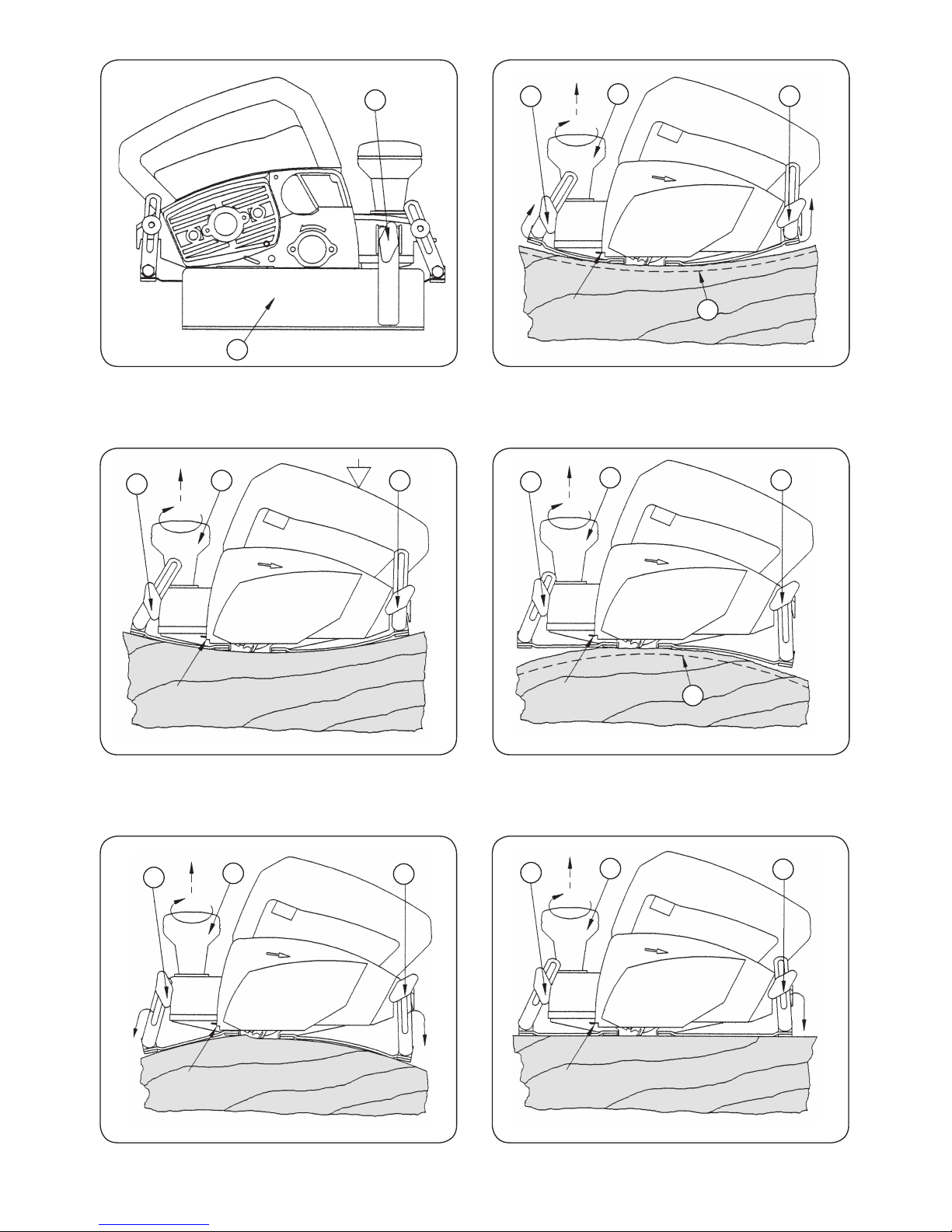
20
L
P
R
A
B
C
"0"
SU PER FI CIE CON CA VA
B
"0"
SU PER FI CIE CON CA VA
A
C
SU PER FI CIE CONVEXA
"0"
B
C
R
A
Fig. 1 Fig. 2
Fig. 3
Fig. 4
SU PER FI CIE CONVEXA
"0"
B
C
A
SU PER FI CIE HORIZONTAL
"0"
B
C
A
Fig. 5
Fig. 6
Page 21
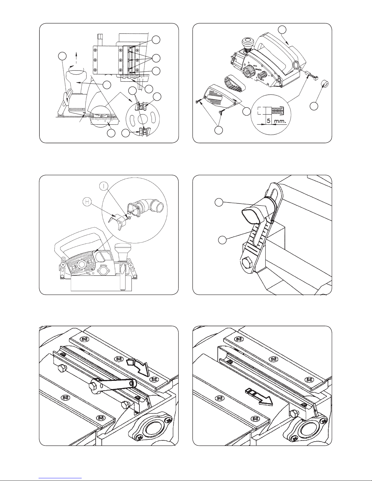
21
"0"
D
S
D
E
S
E
D
E
C
A
G
J
J
F
K
L
Fig. 8
Fig. 7
Fig. 9
Fig. 10
Fig. 11
Fig. 12
Page 22

22
Fig. 14
Fig. 13
Fig. 16
Fig. 15
Page 23

23
Page 24

MÁQUINAS Y HERRAMIENTAS PARA LA MA DE RA
Edición Noviembre 2005
Antoni Capmany, 1 • Tel. 934 329 898 • Fax 934 329 899
Web: www.virutex.es • E-mail: info@virutex.es
08028 Barcelona • ESPAÑA
 Loading...