

Page 1
MANUAL DE INSTRUCCIONES
OPERATING INSTRUCTIONS
MODE D’ EMPLOI
GEBRAUCHSANWEISUNG
MANUALE D’ISTRUZIONI
MANUAL DE INSTRUÇÕES
ИНСТРУКЦИЯ ПО ЭКСПЛУАТАЦИИ
CE23N
VIDEO DEMO
www.virutex.es
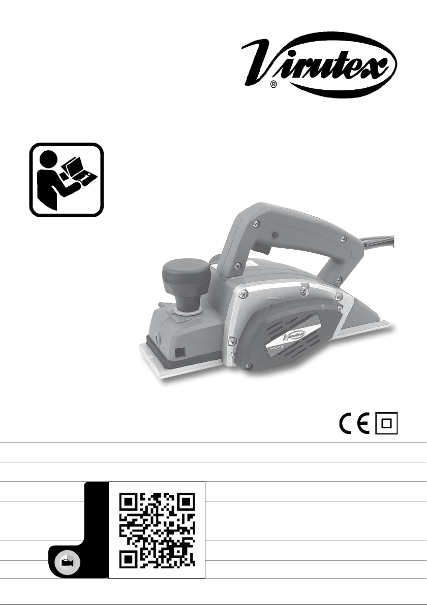
Cepillo lijador
Abrasive planer
Rabot ponceur
Schleifhobel
Pialletto abrasivo
Plaina lixadoral
Абразивный Рубанок
Page 2
MANUAL DE INSTRUCCIONES
OPERATING INSTRUCTIONS
MODE D'EMPLOI
GEBRAUCHSANWEISUNG
MANUALE D'ISTRUZIONI
MANUAL DE INSTRUÇÕES
ИНСТРУКЦИЯ
ПО
ЭКСПЛУАТАЦИИ
ESPAÑOL Cepillo lijador CE23N
ENGLISH CE23N Abrasive planer
FRANÇAIS Rabot ponceur CE23N
DEUTSCH Schleifhobel CE23N
ITALIANO Pialletto abrasivo CE23N
PORTUGUÉS Plaina lixadora CE23N
РУССКИЙ CE23N Абразивный Рубанок
página/page
seite/pagina
страница
2
5
7
9
12
14
17
ESPAÑOL
CEPILLO LIJADOR CE23N
(Ver imágenes pág. 21, 22)
1. INSTRUCCIONES DE SEGURIDAD
PARA EL MANEJO DEL CEPILLO
Antes de utilizar la máquina, lea
atentamente el FOLLETO DE INSTRUCCIONES GENERALES DE SEGURIDAD
que se adjunta con la documentación
de la misma.
1. Asegúrese antes de conectar la máquina, que la
tensión de alimentación, corresponda con la indicada
en la chapa de características.
2. Antes de poner en marcha la máquina, asegúrese
que el rodillo abrasivo esta bien sujeto y no roza con
ninguna otra parte de la máquina.
3. Antes de empezar el trabajo, asegúrese que la
superficie a lijar no tiene clavos o ángulos afilados
que puedan dañar el rodillo abrasivo.
4. Mantenga siempre las manos alejadas del área de
lijado, y sujete siempre la máquina por la empuñadura.
5. El polvo producido durante el lijado puede resultar
2
tóxico o nocivo para la salud. Es necesario utilizar
siempre la conexión para la aspiración de polvo.
6. También es recomendable trabajar con aspiración,
para prolongar la vida del rodillo abrasivo.
7. Esperar a que la máquina este completamente
parada antes de soltarla o apartarla.
8. Desconecte la máquina de la red eléctrica antes
de realizar cualquier operación de mantenimiento.
9. Deberían utilizarse protectores auditivos durante
el uso de la máquina (Ver capítulo13)
10. Use siempre recambios originales VIRUTEX.
2. CARACTERÍSTICAS TÉCNICAS
Voltaje........................................................230 V
Potencia absorbida...................................700W
Motor universal......................................50/60 Hz
R.p.m en vacío........................................16.500
Ancho de lijado..........................................81 mm
Profundidad de lijado máx...........................1 mm
Peso.........................................................3,2 Kg
Nivel de Presión acústica Ponderado A..............88 dBA
Nivel de Potencia acústica Ponderada A................99 dBA
Incertidumbre de la medición..............................K = 3 dBA
¡Usar protectores auditivos!
Nivel total de emisión de vibraciones..............a
Incertidumbre de la medición.........................K: 1,5 m/s
: <2,5 m/s
h
2
2
Page 3
3. EQUIPO ESTÁNDAR
En el interior de la caja Ud. encontrará los elementos
siguientes:
1. Cepillo lijador CE23N equipado con rodillo abrasivo
de Grano 50
2. Escuadra guía lateral
3. Llave allen e/c 3 mm
4. Toma aspiración
5. Manual de instrucciones
4. HERRAMIENTAS
REF. DENOMINACION
2345510 Rodillo abrasivo Gr. 40 Carborundum
2345511 Rodillo abrasivo Gr. 50 "
2345512 Rodillo abrasivo Gr. 60 "
2345514 Rodillo abrasivo Gr. 60 Oxido de circonio
El cepillo va equipado con un interruptor de seguridad
con enclavamiento invertido que no permite puestas
en marcha accidentales de la máquina.
Para poner en marcha la máquina, pulsar sobre el
seguro del pulsador D y simultáneamente pulsar sobre
el botón de interruptor E (Fig. 2)
8. AJUSTE DE LA PROFUNDIDAD DE PASADA
Cuando se deban realizar trabajos de desbaste y/o
alisados o acabados girar el pomo G (Fig. 2) hasta
conseguir la profundidad de pasada necesaria (Profundidad máxima de lijado 1 mm)
Para realizar el achaflanado de los bordes de una
pieza de una manera rápida y sencilla, situar la ranura
delantera "V" del centro del patín del cepillo, sobre el
borde de la pieza y avanzar el cepillo uniformemente,
manteniendo el ángulo de 45° (Fig. 3)
5. ACCESORIOS OPCIONALES
6446073 Acoplamiento aspiración
6. DESCRIPCION GENERAL Y APLICACIONES
El cepillo lijador CE23N es una herramienta útil para
carpinteros, montadores, restauradores y astilleros
náuticos. Está especialmente diseñado para trabajos
de rebaje y/o alisado de: maderas, maderas barnizadas,
maderas estratificadas, maderas blandas y materiales
tales como fibra de vidrio, y fibra de carbono reforzada
con resinas epoxi, vinílicas y poliester.
Para obtener el mejor rendimiento de la máquina y
alargar al máximo la vida del rodillo abrasivo, rogamos
siga las siguientes indicaciones:
- Sitúe la profundidad de pasada según la dureza del
material que vaya a lijar, de modo que le permita
avanzar con cierta celeridad, con lo que evitará
una pérdida excesiva de velocidad del rodillo y su
consiguiente calentamiento.
- Cambie el rodillo abrasivo cuando esté gastado.
Un rodillo muy gastado extrae muy poco material y
calienta excesivamente el motor y el propio rodillo.
La máquina va provista de toma de aspiración, por
la que puede conectarse, mediante el acoplamiento
aspirador estandar (ref. 6446073) a nuestros aspiradores AS182K, AS282K o a cualquier aspirador
industrial. Para el montaje de la toma de aspiración,
desmontar la guía de salida de viruta A (Fig. 1), mediante el tornillo B y montar la toma de aspiración
C en el mismo alojamiento.
7. PUESTA EN MARCHA Y
PARO DE LA MÁQUINA
9. CAMBIO DEL RODILLO ABRASIVO
Desconectar la máquina de la red
eléctrica, antes de efectuar cualquier
operación de mantenimiento.
Para realizar el cambio del rodillo abrasivo proceder
de la siguiente manera:
- Aflojar el pomo J (Fig. 4)
- Retirar la tapa de protección K (Fig. 4) levantándola
primero por la solapa y girando hasta dejar libre el
acceso al rodillo abrasivo L (Fig. 4)
- Aflojar la tuerca de blocaje M (Fig. 4)
- Extraer el rodillo abrasivo L (Fig. 4) desplazándolo
lateralmente.
Asegúrese de que el cabezal del rodillo
N (Fig. 5) esté totalmente exento de
virutas, polvo etc antes de proceder al
montaje del nuevo rodillo abrasivo.
Antes de insertar el nuevo rodillo, verificar también
que las juntas tóricas O-P (Fig. 5) se encuentran en
buen estado, sin presencia de grietas o mordeduras,
y correctamente montadas en su alojamiento.
Insertar el nuevo rodillo procediendo en sentido
inverso al explicado para el montaje.
- Comprobar que el rodillo está enrasado con la
base H (Fig. 6), si precisa de ajuste proceda de la
siguiente manera:
- Subir o bajar la base H (Fig. 7), accionando sobre
el husillo de regulación I (Fig. 7), mediante la llave
3
Page 4

allen e/c 3 mm que se suministra con la máquina
hasta que el rodillo quede alineado con la base (Fig. 6)
Mantener libres y limpias, las aberturas de ventilación
y refrigeración de la máquina.
10. CAMBIO DE LAS JUNTAS TORICAS
Si observase que las juntas tóricas se encuentran
deterioradas para su cambio proceder de la siguiente
manera:
- Extraer la tuerca M, el casquillo prensor Q y las
juntas tóricas O (Fig. 5) poniendo en su lugar las
nuevas juntas originales VIRUTEX.
- Extraer las juntas tóricas P de sus correspondientes ranuras en el cabezal N y casquillo prensor Q
sustituyéndolas por las nuevas juntas originales
VIRUTEX (Fig. 5)
11. CAMBIO DE LA CORREA DE TRANSMISION
Extraer la protección R desenroscando los tornillos
S (Fig. 8). Sustituir la correa deteriorada T por otra
original VIRUTEX teniendo la precaución de engranarla correctamente con los dientes de la polea y
sin forzarla.
12. MANTENIMIENTO
ESCOBILLAS Y COLECTOR
Desconectar la máquina de la red
eléctrica, antes de efectuar cualquier
operación de mantenimiento.
Es importante sustituir las escobillas cuando tengan
una longitud mínima de 5 mm. (Ver detalle en Fig. 5)
Cambio de escobillas.
Desenroscar los tapones de color negro U (Fig. 5) de la
carcasa y extraer la escobilla de la guía. Sustituir las
escobillas por unas originales VIRUTEX y comprobar
que deslizan suavemente dentro de sus guías. Roscar
nuevamente el tapón que los encierra y dejar la
máquina en marcha durante 15 min.
14. NIVEL DE RUIDO Y VIBRACIONES
Los niveles de ruido y vibraciones de esta herramienta eléctrica han sido medidos de acuerdo con
la Norma Europea EN 60745-2-14 y EN 60745-1 y
sirven como base de comparación con máquinas de
semejante aplicación.
El nivel de vibraciones indicado ha sido determinado
para las aplicaciones principales de la herramienta,
y puede ser utilizado como valor de partida para la
evaluación de la exposición al riesgo de las vibraciones. Sin embargo, el nivel de vibraciones puede
llegar a ser muy diferente al valor declarado en
otras condiciones de aplicación, con otros útiles de
trabajo o con un mantenimiento insuficiente de la
herramienta eléctrica y sus útiles, pudiendo llegar a
resultar un valor mucho más elevado debido a su ciclo
de trabajo y modo de uso de la herramienta eléctrica.
Por tanto, es necesario fijar medidas de seguridad de
protección al usuario contra el efecto de las vibraciones, como pueden ser mantener la herramienta y
útiles de trabajo en perfecto estado y la organización
de los tiempos de los ciclos de trabajo (tales como
tiempos de marcha con la herramienta bajo carga,
y tiempos de marcha de la herramienta en vacío y
sin ser utilizada realmente ya que la reducción de
estos últimos puede disminuir de forma sustancial
el valor total de exposición).
15. GARANTÍA
Todas las máquinas electroportátiles VIRUTEX tienen
una garantía válida de 12 meses, a partir del día de su
suministro, quedando excluidas todas las manipulaciones o daños ocasionados por manejo inadecuado
o por desgaste natural de la máquina.
Para cualquier reparación, dirigirse al Servicio Oficial
de Asistencia Técnica VIRUTEX.
Si observa que el colector presenta quemaduras o resaltes, debe hacerlo reparar
en un Servicio Técnico VIRUTEX.
13. LIMPIEZA DE LA MÁQUINA
Es importante limpiar siempre cuidadosamente la
máquina después de su utilización mediante un
soplado de aire seco.
Mantener el cable de alimentación en perfectas
condiciones de uso.
4
VIRUTEX, se reserva el derecho de modificar sus
productos sin previo aviso.
Page 5

ENGLISH
CE23N ABRASIVE PLANER
(See figures in pages 21, 22)
1. SAFETY INSTRUCTIONS
FOR HANDLING THE PLANER
Before using the machine, carefully
read the GENERAL SAFETY INSTRUCTIONS LEAFLET enclosed with the
machine documentation.
1. Before plugging in the machine, ensure that the
power supply voltage corresponds to what is stated
on the machine's characteristics plate.
2. Before starting up the machine, ensure that the
abrasive roller is properly fastened in place and does
not rub against any other part of the machine.
3. Before starting to work, make sure that there are
no nails or sharp angles on the surface to be sanded
that could damage the abrasive roller.
4. Always keep hands clear of the sanding area and
grasp the machine by the handgrip.
5. The dust produced during sanding may prove to
be toxic or harmful to your health, and therefore it
is necessary that the machine always be connected
to a dust collector.
6. It is also recommended that dust collection be used
in order to prolong the life of the abrasive roller.
7. Wait until the machine has come to a complete
stop before putting it down or storing it.
8. Unplug the machine from the electrical outlet
before performing any maintenance operations.
9. Wear earplugs when using the machine (see
chapter 13)
10. Always use original VIRUTEX spare parts.
2. SPECIFICATIONS
Voltage.......................................................230 V
Input power................................................700 W
Motor.....................................................50/60Hz
No-load speed (rpm).................................16,500
Sanding width…........................................81 mm
Max. sanding depth…..................................1 mm
Weight......................................................3,2 Kg
Weighted equivalent continuous
acoustic pressure level A.......................................88 dBA
Acoustic power level A............................................99 dBA
Uncertainty............................................................K = 3 dbA
Wear ear protection!
Vibration total values........................................a
Uncertainty...........................................................K: 1.5 m/s
: <2.5 m/s
h
3. STANDARD EQUIPMENT
Inside the box you willfind the following components:
1. CE23N abrasive planer fitted with 50-grain
abrasive roller.
2. Lateral fence
3. 3-mm Allen key
4. Dust collector nozzle
5. Instructions manual
4. TOOLS
CODE DESCRIPTION
2345510 40-grain Carborundum abrasive roller
2345511 50-grain Carborundum abrasive roller
2345512 60-grain Carborundum abrasive roller
2345514 60-grain zirconium oxide abrasive roller
5. OPTIONAL ACCESSORIES
6446073 Dust collector attachment
6. GENERAL DESCRIPTION
AND APPLICATIONS
The CE23N abrasive planer is a tool that will prove
useful to carpenters, fitters, restorers and shipwrights.
It is especially designed for the shaving and/or sanding
of: wood, varnished wood, stratified wood, softwood
and such materials as fibreglass and carbon fibre
reinforced with epoxy, vinyl and polyester resins.
To enhance the machine performance and working life
of the abrasive roller, we recommend the following:
- set the pass depth according to the hardness of
the material to be sanded, so that the machine may
be moved at a reasonable speed, thus preventing
overheating due to excessive loss of roller speed.
- change the abrasive roller once worn; a worn roller
does not sand effectively and causes the motor and
the roller itself to overheat.
The machine is equipped with a dust collector connection which can be used for connection to our
AS182K, AS282K dust collector or any industrial
equivalent via the STANDARD DUST COLLECTOR
ATTACHMENT (ref. 6446073). For assembling the dust
collector connection, remove the chips outlet guide
A (Fig. 1) using screws B and fit the dust collector
2
2
5
Page 6
connection in its place.
7. STARTING AND STOPPING THE MACHINE
The planer is equipped with an upwardly-engaging
safety button, which avoids the machine from being
started up accidentally.
To start up the machine, press down on the safety
button D while depressing the power button E (Fig. 2).
8. ADJUSTING PASS DEPTH
When trimming and/or smoothing or finishing work
is required, turn knob G (Fig. 2) until the proper pass
depth is achieved (maximum sanding depth: 1 mm).
To chamfer the edges of a workpiece quickly and
easily, place the front groove "V" of the centre of
the planer shoe onto the workpiece edge and guide
the planer forward evenly, maintaining an angle of
45º (Fig. 3).
wrench supplied with the machine until the roller
is aligned with the base (Fig. 6)
10. CHANGING O-RING SEALS
If it is observed that O-ring seals are worn out,
proceed as follows to replace them:
- Remove the nut M, the press cap Q and the O-ring
seals O (Fig. 5), replacing them with new original
VIRUTEX seals.
- Remove the O-ring seals P from their grooves in
the roller head N and press cap Q, replacing them
with new original VIRUTEX seals (Fig. 5)
11. CHANGING THE TRANSMISSION BELT
Unscrew screws S (Fig. 8) and remove protection
R. Replace the worn belt T with a VIRUTEX original
spare, taking care to fit it correctly into the pulley
cogs, never forcing it.
9. CHANGING THE ABRASIVE ROLLER
Unplug the machine from the electrical
outlet before performing any maintenance operation.
In order to change the abrasive roller, proceed as
follows:
- Loosen knob J (Fig. 4)
- Remove the protective cover K (Fig. 4), first lifting
it by the tab and swivelling it until the abrasive roller
L can be accessed freely (Fig. 4)
- Loosen the lock nut M (Fig. 4)
- Remove the abrasive roller L (Fig. 4), sliding it off
laterally.
Ensure that the roller head N (Fig. 5) is
totally free of chips, dust, etc, before
installing the new abrasive roller.
Before inserting the new roller, also check that the
O-ring seals O-P (Fig. 5) are in good condition and
show no signs of cracking or pitting, and are correctly
fitted in place.
Insert the new roller, following the steps provided
for disassembly in inverse order.
- Check that the roller is flush with the base H (Fig.
6); if it requires adjustment, proceed as follows:
- Raise or lower the base H (Fig. 7) by turning the
regulating screw I (Fig. 7) with the 3-mm a/f Allen
6
12 MAINTENANCE OF THE
BRUSHES AND COLLECTOR
Disconnect from the mains before
carrying out any maintenance operations.
The brushes must be replaced when they reach a
minimum length of 5 mm (Fig. 5)
Unscrew the black caps U (Fig. 5) on the housing and
remove the brushes from the guide. Replace them
with new Virutex original spares, ensuring that they
move smoothly inside the guides. Screw on the cap
which covers them and leave the machine running
for 15 minutes.
If the collector is burned or uneven
it should be repaired by a Virutex
service agent.
13. CLEANING THE MACHINE
It is important to always clean the machine carefully
after use with a dry air blower.
Keep the power cable in perfect condition.
Keep the machine's vent and cooling openings clean
and unobstructed.
14. NOISE AND VIBRATION LEVEL
The noise and vibration levels of this device have
been measured in accordance with European stan-
Page 7

dard EN 60745-2-14 and EN 60745-1 and serve as
a basis for comparison with other machines with
similar applications.
The indicated vibration level has been determined
for the device’s main applications and may be used
as an initial value for evaluating the risk presented
by exposure to vibrations. However, vibrations
may reach levels that are quite different from the
declared value under other application conditions,
with other tools or with insufficient maintenance
of the electrical device or its accessories, reaching a
much higher value as a result of the work cycle or
the manner in which the electrical device is used.
Therefore, it is necessary to establish safety measures
to protect the user from the effects of vibrations,
such as maintaining both the device and its tools
in perfect condition and organising the duration
of work cycles (such as operating times when the
machine is subjected to loads, and operating times
when working with no-load, in effect, not in use, as
reducing the latter may have a considerable effect
upon the overall exposure value).
15. WARRANTY
All VIRUTEX power tools are guaranteed for 12 months
from the date of purchase, excluding any damage
which is a result of incorrect use or of natural wear and
tear on the machine. All repairs should be carried out
by the official VIRUTEX technical assistance service.
VIRUTEX reserves the right to modify its products
without prior notice.
d'alimentation correspond à celle indiquée sur la
plaque des caractéristiques.
2. Avant de mettre en marche la machine, s'assurer
que le rouleau abrasif est bien fixé et ne frotte pas
sur une partie quelconque de la machine.
3. Avant de commencer à travailler, s'assurer que la
surface à poncer n'a pas de clous ou d'angles affilés
qui pourraient endommager le rouleau abrasif.
4. Maintenir toujours les mains éloignées de la zone de
ponçage et tenir toujours la machine par la poignée.
5. La poussière produite par le ponçage peut être
toxique ou nocive pour la santé. Il faut toujours
utiliser le système d'aspiration pour la poussière.
6. Il est également recommandé de travailler avec
l'aspiration pour prolonger la durée de vie utile du
rouleau abrasif.
7. Attendre que la machine soit complètement arrêtée
avant de la lâcher ou de la ranger.
8. Débrancher la machine du secteur, avant toute
opération d'entretien.
9. Il faut utiliser des protections auditives quand on
utilise la machine (voir chapitre 13).
10. Utiliser toujours des pièces de rechange d'origine
VIRUTEX.
2. CARACTERISTIQUES
Tension...................................................... 230 V
Puissance absorbée..................................700 W
Moteur...................................................50/60 Hz
tr/min à vide...............................................16 500
Largeur de ponçage...................................81 mm
Profondeur de ponçage max........................1 mm
Poids.........................................................3,2 Kg
FRANÇAIS
RABOT PONCEUR CE23N
(Voir images p. 21, 22)
1. INSTRUCTIONS DE SÉCURITÉ
POUR LE MANIEMENT DU RABOT
Avant d'utiliser la machine, veuillez
lire attentivement la BROCHURE
D'INSTRUCTIONS GÉNÉRALES DE
SÉCURITÉ qui est jointe à la documentation de la machine.
1. Vérifier avant de brancher la machine si la tension
Niveau de pression acoustique
continu équivalent pondéré A...............................88 dBA
Niveau de puissance acoustique A........................99 dBA
Incertitude..........................................................K = 3 dbA
Porter une protection acoustique!
Valeurs totales des vibrations........................a
Incertitude.........................................................K: 1,5 m/s
: <2,5 m/s
h
3. ÉQUIPEMENT STANDARD
Dans la mallette, se trouvent les éléments suivants:
1. Rabot ponceur CE23N équipé d'un rouleau abrasif
Grain 50
2. Équerre guide latérale
3. Clé six pans o/c 3 mm
4. Buse d'aspiration
5. Manuel d'instructions
2
2
7
Page 8

4. OUTILS
RÉF. DÉNOMINATION
2345510 Rouleau abrasif Gr. 40 Carborundum
2345511 Rouleau abrasif Gr. 50 "
2345512 Rouleau abrasif Gr. 60 "
2345514 Rouleau abrasif Gr. 60 Oxyde de zirconium
5. ACCESSOIRES EN OPTION
6446073 Accordement aspiration.
6. DESCRIPTION GÉNÉRALE
ET APPLICATIONS
Le rabot ponceur CE23N est un outil très utile pour
les menuisiers, les installateurs, les restaurateurs et
les chantiers navals. Il est particulièrement conçu
pour des travaux de délardement et/ou de ponçage
de: bois, bois vernis, stratifiés, bois tendres et des
matériaux tels que la fibre de verre et la fibre de
carbone renforcée avec des résines époxy, vinyliques
et polyester.
Pour obtenir le meilleur rendement de la machine
et prolonger au maximum la durée de vie utile du
rouleau abrasif, il faut suivre les indications suivantes:
- Régler la profondeur de passage en fonction de la
dureté du matériau à poncer, pour pouvoir avancer
avec une certaine rapidité, ce qui évitera une perte
excessive de vitesse du rouleau et l'échauffement
correspondant.
- Remplacer le rouleau abrasif quand il est usé. Un
rouleau très usé extrait très peu de matériau et chauffe
excessivement le moteur et le rouleau, lui-même.
La machine est pourvue d'une buse d'aspiration, qui
permet de brancher à l'aide de l'ACCOUPLEMENT
D'ASPIRATEUR STANDARD (réf. 6446073) notre aspirateur AS182K, AS282K, ou tout autre aspirateur
industriel. Pour le montage de la buse d'aspiration,
démonter le guide de sortie de copeaux A (Fig. 1), à
l'aide des vis B et monter la buse d'aspiration dans
le même logement.
7. MISE EN MARCHE ET ARRÊT DE LA MACHINE
Le rabot est équipé d'un interrupteur de sécurité à
enclenchement inversé qui empêche les mises en
marche accidentelles de la machine.
Pour mettre en marche la machine, appuyer sur la
sécurité du bouton D et simultanément appuyer sur
le bouton de l'interrupteur E (Fig. 2)
8. RÉGLAGE DE LA
PROFONDEUR DE PASSAGE
8
Pour réaliser des travaux de dégrossissage et/ou de
ponçage ou de finition, tourner le bouton G (Fig. 2)
pour obtenir la profondeur de passage nécessaire
(profondeur maximum de ponçage 1 mm).
Pour faire le chanfreinage des bords d'une pièce de
manière rapide et simple, situer la rainure avant du
centre du patin du rabot sur le bord de la pièce et
maintenir une vitesse constante d'avance du rabot
en conservant l'angle de 45° (Fig. 3)
9. CHANGEMENT DU ROULEAU ABRASIF
Débrancher la machine du secteur,
avant toute opération d'entretien.
Pour changer le rouleau abrasif, procéder comme suit:
- Dévisser le bouton J (Fig. 4)
- Retirer le couvercle de protection K (Fig. 4) en le
soulevant tout d'abord par le revers et en le tournant
pour libérer l'accès au rouleau abrasif L (Fig. 4)
- Dévisser l'écrou de blocage M (Fig. 4)
- Extraire le rouleau abrasif L (Fig. 4) en le déplaçant
latéralement.
S'assurer que la tête du rouleau N
(Fig. 5) est propre, sans copeaux ni
poussière, etc, avant de monter un
nouveau rouleau abrasif.
Avant d'insérer le nouveau rouleau, vérifier également
que les joints toriques O-P (Fig. 5) sont en bon état,
sans fissures ou déchirures, et correctement montés
dans leur logement.
Insérer le nouveau rouleau en sens inverse de celui
expliqué pour le montage.
- Vérifier si le rouleau est bien au ras du socle H (Fig.
6), s'il faut le régler, procéder comme suit:
- Lever ou baisser le socle H (Fig. 7), en actionnant
la vis de réglage I (Fig. 7), à l'aide de la clé six pans
o/c 3 mm, fournie avec la machine, pour aligner le
rouleau avec le socle (Fig. 6)
10. CHANGEMENT DES JOINTS TORIQUES
Si les joints toriques sont détériorés, pour les changer,
procéder comme suit:
- Retirer l'écrou M, la douille de pression Q et les
joints toriques O (Fig. 5) en mettant à leur place les
nouveaux joints d'origine VIRUTEX.
- Retirer les joints toriques P de leurs rainures correspondantes dans la tête N et la douille de pression Q
Page 9

en les remplaçant par les nouveaux joints d'origine
VIRUTEX (Fig. 5)
11. CHANGEMENT DE LA COURROIE
DE TRANSMISSION
Extraire la protection R en dévissant les vis S (Fig.
8). Remplacer la courroie abîmée T par une d'origine
VIRUTEX en faisant en sorte de bien l'engrener sur
les dents de la poulie, sans la forcer.
12. ENTRETIEN DES BALAIS
ET DU COLLECTEUR
Débrancher la machine du secteur,
avant de faire toute opération
d'entretien.
Il est important de changer les balais quand ils ont
une longueur minimum de 5 mm (Fig. 5)
Dévisser le bouchon noir U (Fig. 5) de la carcasse et
extraire le balai du guidage. Remplacer les balais par
des balais d'origine VIRUTEX et vérifier s'ils glissent
doucement dans leurs guidages. Revisser le bouchon
et laisser la machine en marche pendant 15 mm.
Si le collecteur présente des brûlures
ou des ressauts, il est recommandé de
le faire réparer par un service technique VIRUTEX.
outils de travail ou lorsque l’entretien de l’appareil
électrique et de ses outils est insuffisant, il peut arriver
que le niveau de vibrations soit très différent de la
valeur déclarée, voire même beaucoup plus élevé en
raison du cycle de travail et du mode d'utilisation de
l'appareil électrique.
Il est donc nécessaire de fixer des mesures de sécurité
pour protéger l'utilisateur contre les effets des vibrations, notamment garder l’appareil et les outils de
travail en parfait état et organiser les temps des cycles
de travail (temps de fonctionnement avec l’appareil
en service, temps de fonctionnement avec l’appareil
à vide, sans être utilisé réellement), car la diminution
de ces temps peut réduire substantiellement la valeur
totale d’exposition.
15. GARANTIE
Tous les machines électro-portatives VIRUTEX ont
une garantie valable 12 mois à partir de la date
d'achat, en étant exclus toutes manipulations ou
dommages causés par des maniements inadéquats
ou par l'usure naturelle de la machine. Pour toute
réparation, s'adresser au service officiel d'assistance
technique VIRUTEX.
VIRUTEX se réserve le droit de modifier ses produits
sans avis préalable.
DEUTSCH
13. NETTOYAGE DE LA MACHINE
Il est important de toujours bien nettoyer la machine
après l'emploi avec un soufflage d'air sec.
Conserver le câble d'alimentation en parfait état.
Les ouvertures de ventilation et de refroidissement
de la machine doivent être nettoyées pour éviter
toute obstruction.
14. NIVEAU DE BRUIT ET DE VIBRATIONS
Les niveaux de bruit et de vibrations de cet appareil
électrique ont été mesurés conformément à la norme
européenne EN 60745-2-14 et EN 60745-1 et font
office de base de comparaison avec des machines
aux applications semblables.
Le niveau de vibrations indiqué a été déterminé pour
les principales applications de l’appareil, et il peut
être pris comme valeur de base pour l’évaluation du
risque lié à l’exposition aux vibrations. Toutefois,
dans d’autres conditions d’application, avec d’autres
SCHLEIFHOBEL CE23N
(SIEHE ABB. SEITE 21, 22)
1. UNFALLVERHÜTUNGSVORSCHRIFTEN
FÜR DIE BEDIENDUNG DES HOBELS
Lesen Sie vor der Benutzung der Maschine sorgfältig die den Unterlagen
der Maschine beigelegte BROSCHÜRE
ÜBER DIE ALL GE MEINENEN UNFALLVERHÜTUNGSVORSCHRIFTEN.
1. Prüfen Sie vor dem Anschließen der Maschine,
ob die Netzspannung mit den Angaben auf dem
Typenschild übereinstimmt.
2. Stellen Sie vor Inbetriebnahme der Maschine sicher,
dass die Schleifrolle fest eingesetzt ist und nicht an
anderen Maschinenteilen streift.
9
Page 10

3. Stellen Sie vor Arbeitsbeginn sicher, dass die zu
schleifende Fläche keine Nägel oder spitzen Winkel
aufweist, welche die Schleifrolle beschädigen
könnten.
4. Lassen Sie Ihre Hände immer außerhalb des
Schleifbereichs, und halten Sie die Maschine immer
am dafür vorgesehenen Griff.
5. Der beim Schleifen entstehende Schleifstaub kann
giftig oder gesundheitsschädlich sein. Der Anschluss
an die Staubabsaugung muss daher immer verwendet
werden.
6. Das Arbeiten mit Absaugung ist auch empfehlenswert, um die Lebensdauer der Schleifrolle zu
verlängern.
7. Warten Sie ab, bis die Maschine ganz steht, bevor
Sie sie loslassen oder wegstellen.
8. Ziehen Sie immer den Netzstecker, bevor Sie
Wartungsarbeiten an der Maschine durchführen.
9. Während des Arbeitens mit der Maschine ist Gehörschutz zu tragen (siehe Kapitel 13)
10. Verwenden Sie immer Original-Ersatzteile von
VIRUTEX.
2. TECHNISCHE DATEN
Spannung..................................................230 V
Leistungsaufnahme..................................700 W
Motor.....................................................50/60 Hz
U/min im Leerlauf......................................16.500
Schleifbreite.............................................81 mm
Schleiftiefe max...........................................1 mm
Gewich......................................................3,2 Kg
Gewichteter akustischer Dauerdruckpegel A......88 dBA
Akustischer Druckpegel A......................................99 dBA
Unsicherheit..............................................................K = 3 dBA
Gehörschutz tragen!
Schwingungsgesamtwerte...........................a
Unsicherheit.........................................................K = 1,5 m/s
: <2,5 m/s
h
3. STANDARDAUSSTATTUNG
Der Karton enthält folgenden Lieferumfang:
1. Schleifhobel CE23N, bestückt mit Schleifrolle der
Körnung 50
2. Seitliche Winkelschiene.
3. Inbusschlüssel, SW 3 mm
4. Anschluss Absaugung
5. Betriebshandbuch
4. WERKZEUGE
NR. BEZEICHNUNG
10
2345510 Schleifrolle Körnung 40 Karborund
2345511 Schleifrolle Körnung 50 "
2345512 Schleifrolle Körnung 60 "
2345514 Schleifrolle Körnung 60 Zirkonoxid
5. OPTIONALES ZUBEHÖR
6446073 Saugkupplung
6. GESAMTBESCHREIBUNG
UND ANWENDUNGEN
Der Schleifhobel CE23N ist ein nützliches Werkzeug
für Schreiner, Monteure, Restauratoren und Bootsbauer. Er ist insbesondere zum Abtragen bzw. Glätten
folgender Werkstoffe ausgelegt: Holz, lackiertes
Holz, Schichtholz, Weichholz und Werkstoffe wie
Glasfaser und mit Epoxyd-, Vinyl- und Polyesterharz
verstärkte Kohlefaser.
Befolgen Sie bitte folgende Hinweise für einen
optimalen Betrieb des Geräts und eine maximale
Lebensdauer der Schleifrolle:
- Stellen Sie die Bearbeitungstiefe entsprechend der
Härte des zu beschleifenden Materials ein. Durch die
korrekte Regulierung der Vorschubgeschwindigkeit
wird ein zu hoher Geschwindigkeitsverlust und somit
eine Erhitzung der Rolle vermieden.
- Wechseln Sie die Schleifrolle aus, sobald sie abgenutzt ist. Beim Betrieb mit einer stark abgenutzten
Schleifrolle wird nur wenig Material abgetragen,
was die Überhitzung des Motors und der Rolle selbst
zur Folge hat.
Die Maschine hat einen Sauganschluß, wo mit Hilfe
des ANSCHLUSSES FÜR STANDARDSAUGER (Best.Nr. 6446073) unser Sauger AS182K, AS282K oder
irgendein anderer Industriesauger angebracht werden
kann. Für die Anbringung des Sauganschlusses mit
den Schrauben B den Spanauslaß A abmontieren
(Abb. 1) und den Sauganschluß in der gleichen
2
Aufnahme befestigen.
2
7. EIN- UND AUSSCHALTEN DER MASCHINE
Der Hobel ist mit einem Sicherheitsschalter mit
Abhängigkeitsverschluss ausgestattet, um ein
nicht beabsichtigtes Einschalten der Maschine zu
verhindern.
Zum Einschalten der Maschine auf die Sicherung des
Schalters D drücken und gleichzeitig den Einschaltknopf E (Abb. 2) betätigen.
8. EINSTELLEN DER BEARBEITUNGSTIEFE
Wenn Arbeiten zum Abtragen und/oder Glätten oder
zur Oberflächenbearbeitung durchzuführen sind, den
Page 11

Griff G (Abb. 2) drehen, bis die erforderliche Bearbeitungstiefe erreicht ist (maximale Schleiftiefe 1 mm).
Zum schnellen, einfachen Anfasen der Kanten eines
Werkstücks die Nut vorne in der Mitte des Hobelgleitschuhs auf die Werkstückkante aufsetzen, den
Hobel gleichmäßig vorschieben, und dabei den Winkel
von 45º beibehalten (Abb. 3).
9. WECHSEL DER SCHLEIFROLLE
Ziehen Sie immer den Netzstecker,
bevor Sie Wartungsarbeiten an der
Maschine durchführen!
Zum Auswechseln der Schleifrolle gehen Sie folgendermaßen vor:
- Den Griff J (Abb. 4) lösen
- Die Abdeckkappe K (Abb. 4) abnehmen. Dazu die
Kappe zuerst am Überstand anheben und drehen,
bis der Zugang zur Schleifrolle L offen ist (Abb. 4).
- Die Stoppmutter M (Abb. 4) lösen.
- Die Schleifrolle L (Abb. 4) seitlich verschieben und
herausnehmen.
Stellen Sie sicher, dass das Kopfstück
der Rolle N (Abb. 5) frei von Spänen,
Staubresten usw. ist, bevor Sie die neue
Schleifrolle einsetzen.
Vor dem Einsetzen der neuen Rolle ist auch zu prüfen,
ob die Dichtringe O-P (Abb. 5) in gutem Zustand sind,
keine Risse oder Spuren zeigen und richtig in ihren
Aufnahmen sitzen.
Führen Sie die neue Rolle ein, und gehen Sie dazu in
der umgekehrten Ausbaureihenfolge vor.
- Prüfen Sie, ob die Rolle bündig zur Grundplatte
H (Abb. 6) steht. Wenn nicht, stellen Sie folgendermaßen ein:
- Die Grundplatte H (Abb. 7) mit Hilfe der Einstellspindel I (Abb. 7) anheben bzw. senken, und zwar mit Hilfe
des mit der Maschine mitgelieferten Inbusschlüssels
mit der Schlüsselweite 3 mm, bis die Rolle mit der
Grundplatte bündig ist (Abb. 6).
10. WECHSEL DER DICHTRINGE
Wenn die Dichtringe verschlissen sind, dann wechseln
Sie diese folgendermaßen aus:
- Die Mutter M, die Klemmhülse Q und die Dichtringe
O (Abb. 5) herausnehmen, und die neuen Originaldichtungen von VIRUTEX einsetzen.
- Die Dichtringe P aus ihren jeweiligen Nuten am
Kopfstück N und an der Klemmhülse Q herausnehmen und neue Originaldichtungen von VIRUTEX
einsetzen (Abb. 5).
11. AUSWECHSELN DES ANTRIEBSRIEMENS
Die Schrauben S abdrehen, um die Schutzvorrichtung
R abnehmen zu können (Abb. 8). Den beschädigten
Riemen durch ein Original-VIRUTEX-Ersatzteil ersetzen und dabei aufpassen, daß der neue Riemen
richtig in die Zähne der Riemenscheibe greift ohne
ihn in seine Position zwingen zu müssen.
12. WARTUNG VON
BÜRSTEN UND SCHLEIFRING
Vor allen Wartungsarbeiten den Netzstecker ziehen.
Die Bürsten müssen ersetzt werden, wenn sie eine
Mindestlänge von 5 mm haben. (Abb. 5)
Den schwarzen Stopfen U (Abb. 5) vom Gehäuse abschrauben und die Bürste aus der Führung nehmen. Die
Bürsten durch Original-VIRUTEX-Ersatzteile ersetzen
und überprüfen, daß sie sanft in ihren Führungen
gleiten. Den Stopfen wieder anbringen und festdrehen, und die Maschine ca. 15 Minuten laufen lassen.
Wenn der Schleifring Brandspuren
oder abgesprungene Stellen aufweist
empfehlen wir, ihn vom VIRUTEX-Kundendienst reparieren zu lassen.
13. REINIGEN DER MASCHINE
Die Maschine muss nach der Verwendung immer
sorgfältig durch Abblasen mit trockener Druckluft
gereinigt werden.
Sorgen Sie dafür, dass das Stromkabel immer in
einwandfreiem Zustand ist.
Die Belüftungs- und Kühlöffnungen der Maschine
müssen immer sauber und offen gehalten werden.
14. GERÄUSCHPEGEL
UND VIBRATIONSSTÄRKE
Die Lärm- und Vibrationswerte dieses
Elektrowerkzeugs wurden in Übereinstimmung
mit der europäischen Norm EN 60745-2-14
und EN 60745-1 gemessen und dienen als
Vergleichsgrundlage bei Maschinen für ähnliche
11
Page 12

Anwendungen.
Der angegebene Vibrationspegel wurde für die
wesentlichen Einsatzzwecke des Werkzeugs ermittelt
und kann bei der Beurteilung der Gefahren durch
die Aussetzung unter Vibrationen als Ausgangswert
benutzt werden. Die Vibrationswerte können
sich jedoch unter anderen Einsatzbedingungen,
mit anderen Arbeitswerkzeugen oder bei einer
ungenügenden Wartung des Elektrowerkzeugs oder
seiner Werkzeuge stark vom angegebenen Wert
unterscheiden und aufgrund des Arbeitszyklus
und der Einsatzweise des Elektrowerkzeugs einen
bedeutend höheren Wert aufweisen.
Es ist daher erforderlich, Sicherheitsmaßnahmen
zum Schutz des Anwenders vor den Vibrationen
festzulegen. Dazu können die Aufrechterhaltung
des einwandfreien Zustands des Werkzeugs und der
Arbeitsutensilien sowie die Festlegung der Zeiten der
Arbeitszyklen gehören (wie Laufzeiten des Werkzeugs
unter Last und im Leerlauf, ohne tatsächlich eingesetzt
zu werden, wodurch die Gesamtzeit der Vibrationsauswirkungen bedeutend verringert werden kann).
15. GARANTIE
Alle Elektrowekzeuge von VIRUTEX habe eine garantie
von 12 Montaen ab dem Lieferdatum. Hiervon augeschlossen sind alle Eingriffe oder Schäden aufgrund
von unsachgemässen Gebrauch oder natürlicher
Abnutzung des Geräts.
Wenden Sie sich im Falle einer Reparatur immer an
den zugelassenen Kundendiest von VIRUTEX.
VIRUTEX behält sich das Recht vor, die Produkte ohne
vorherige Ankündigung zu verändern.
1. Prima di collegare l'apparecchio, verificare che
la tensione di alimentazione corrisponda a quella
indicata nella targhetta d'identificazione.
2. Prima di mettere in funzione l'apparecchio, verificare che il rullo abrasivo sia ben fissato e non entri
in contatto con nessun' altra parte dell'apparecchio.
3. Prima di iniziare il lavoro, verificare che, sulla
superficie da levigare, non ci siano chiodi o bordi
taglienti che possano danneggiare il rullo abrasivo.
4. Tenere le mani lontano dall'area da levigare e
afferrare l'apparecchio per l'impugnatura.
5. La polvere prodotta dalle operazioni di levigatura
può essere tossica o nociva per la salute. Utilizzare
sempre un sistema di aspirazione delle polveri collegato all'apposita presa.
6. L'uso di un sistema d'aspirazione è raccomandabile
anche per prolungare la durata del rullo abrasivo.
7. Attendere che la macchina si sia fermata completamente prima di allentare la presa o di separarla
dalla superficie di lavoro.
8. Prima di realizzare qualunque intervento di manutenzione, scollegare l'apparecchio dalla rete elettrica.
9. Durante l'uso della macchina è conveniente usare
protezioni per l'udito (vedere capitolo 13)
10. Usare sempre ricambi originali VIRUTEX.
2. CARATTERISTICHE TECNICHE
Tensione....................................................230 V
Potenza assorbita......................................700 W
Motore..................................................50/60Hz
Velocità a vuoto.........................................16.500
Ampiezza levigatura..................................81 mm
Profondità max. levigatura...........................1 mm
Peso.........................................................3,2 Kg
ITALIANO
PIALLETTO ABRASIVO CE23N
(Vedere figure a Pag. 21, 22)
1. ISTRUZIONI DI SICUREZZA
PER L'USO DEL PIALLETTO
Prima di utilizzare l'apparecchio, leggere attentamente il FOGLIETTO DELLE
ISTRUZIONI GENERALI DI SICUREZZA
allegato alla documentazione.
12
Livello di pressione acustica continuo equivalente pon-
derato A....................................................................88 dBA
Livello di potenza acustica A...................................99 dBA
Incertezza della misura........................................K = 3 dBA
Usare la protezione acustica!
Valori totali delle oscillazioni.........................ah: <2,5 m/s
Incertezza della misura......................................K: 1,5 m/s
3. DOTAZIONE STANDARD
All'interno della scatola troverete i seguenti elementi:
1. Pialletto abrasivo CE23N dotato di rullo abrasivo
Grana 50
2. Squadra guida laterale
3. Chiave a brugola 3 mm
4. Presa aspirazione
2
2
Page 13

5. Manuale d'istruzioni
4. UTENSILI
RIF. NOME
2345510 Rullo abrasivo Gr. 40 Carborundo
2345511 Rullo abrasivo Gr. 50 "
2345512 Rullo abrasivo Gr. 60 "
2345514 Rullo abrasivo Gr. 60 Ossido di zircone
5. ACCESSORI OPTIONAL
6446073 Collegamento aspiratore standard
8. REGOLAZIONE DELLA
PROFONDITÀ DI PASSATA
Quando si devono realizzare lavori di levigatura e/o
lappature o finiture, ruotare la manopola G (Fig. 2)
fino a ottenere la necessaria profondità di passata
(Profondità massima 1 mm).
Per smussare i bordi di un pezzo in modo semplice
e rapido, mettere la fessura anteriore del centro del
pattino del pialletto sul bordo del pezzo, poi fare
avanzare il pialletto a velocità uniforme e sempre a
un angolo di 45º (Fig. 3).
6. DESCRIZIONE GENERALE
E APPLICAZIONI
Il pialletto abrasivo CE23N è uno strumento utile
per carpentieri, montatori, restauratori e cantieri
nautici. È stato appositamente studiato per la
realizzazione di scanalature e/o per la levigatura
di legno, legno verniciato, legno stratificato, legno
morbido e altri materiali come la fibra di vetro e la
fibra di carbonio rinforzata con resine epossidiche,
viniliche e poliestere.
Per ottenere il migliore rendimento della macchina
e allungare al massimo la durata del rullo abrasivo,
si prega di rispettare le indicazioni seguenti:
- Regolare la profondità di passata in funzione della
durezza del materiale da levigare, in modo da poter
avanzare con una certa celerità, evitando così una
perdita eccessiva di velocità del rullo e il conseguente
riscaldamento dello stesso.
- Cambiare il rullo abrasivo quando è consumato. Un
rullo molto consumato asporta pochissimo materiale e
causa il surriscaldamento del motore e del rullo stesso.
La macchina è dotata di un attacco per aspirazione
esterna grazie al quale, tramite il COLLEGAMENTO
ASPIRATORE STANDARD (cod. 6446073), è possibile
collegarla al nostro aspiratore AS182K, AS282K o a
qualsiasi aspiratore industriale. Per montare l'attacco
per aspirazione, smontare la guida di uscita trucioli
A (Fig. 1) svitando le viti B e montare l'attacco per
l'aspirazione nella medesima sede.
7. ACCENSIONE E
SPEGNIMENTO DELL'APPARECCHIO
Il pialletto è dotato di un interruttore con interblocco
di sicurezza che non permette l'accensione accidentale dell'apparecchio.
Per accendere l'apparecchio, premere contemporaneamente la sicura (pulsante D) e l'interruttore
E (Fig. 2)
9. CAMBIO DEL RULLO ABRASIVO
Scollegare la macchina dalla rete
elettrica prima di realizzare qualunque
operazione di manutenzione.
Per sostituire il rullo abrasivo, procedere nel seguente
modo:
- Allentare il pomello J (Fig. 4)
- Spostare il disco di protezione K (Fig. 4) sollevandolo
dalla sua sede e girandolo fino a liberare la zona
d'accesso al rullo abrasivo L (Fig. 4)
- Allentare il dado di bloccaggio M (Fig. 4)
- Estrarre il rullo abrasivo L (Fig. 4) facendolo scorrere
lateralmente.
Verificare che la testa del rullo N (Fig.
5) sia completamente libera da trucioli,
polvere, ecc. prima di procedere al
montaggio del nuovo rullo abrasivo.
Prima di inserire il nuovo rullo, verificare anche che
le guarnizioni ad anello O-P (Fig. 5) siano in buono
stato, senza pieghe o abrasioni, e correttamente
montate al loro posto.
Inserire il nuovo rullo seguendo, in senso inverso, la
procedura di smontaggio.
- Controllare che il rullo sia in linea con la base H
(Fig. 6) e, se deve essere regolato, procedere nel
seguente modo:
- Alzare o abbassare la base H (Fig. 7), agendo sulla
vite di regolazione I (Fig. 7) con la chiave a brugola
3 mm in dotazione, fino al perfetto allineamento del
rullo con la base (Fig. 6)
10. CAMBIO DELLE
GUARNIZIONI AD ANELLO
Se le guarnizioni ad anello sono usurate, sostituirle
13
Page 14

procedendo nel seguente modo:
- Estrarre il dado M, la bussola di serraggio Q e le
vecchie guarnizioni O (Fig. 5) e, al loro posto, montare
nuove guarnizioni originali VIRUTEX.
- Estrarre le guarnizioni P dalle scanalature presenti
sulla testa N e la bussola di serraggio Q. Montare le
nuove guarnizioni originali VIRUTEX (Fig. 5)
11. CAMBIO DELLA CINGHIA
DI TRASMISSIONE
Estrarre la protezione R svitando le viti S (Fig. 8).
Sostituire la cinghia deteriorata con una cinghia
originale VIRUTEX, facendola ingranare perfettamente con i denti della puleggia ma senza forzarla.
12. MANUTENZIONE DELLE
SPAZZOLE E DEL COLLETTORE
Prima di eseguire qualsiasi intervento
di manutenzione sulla macchina, staccarla dalla rete elettrica.
Le spazzole devono essere sostituite quando la loro
lunghezza minima è di 5 mm. (Fig. 5)
Svitare il tappo di colore nero U (Fig. 5) della carcassa ed estrarre la spazzola dalla guida. Montare
delle spazzole originali VIRUTEX e verificare che si
inseriscano delicatamente all'interno delle rispettive
guide. Riavvitare il tappo e far funzionare la macchina
per 15 minuti.
Se il collettore è bruciato o deformato,
si consiglia di farlo riparare presso un
centro di assistenza tecnica VIRUTEX.
13. PULIZIA DELLA MACCHINA
Dopo l'uso, è importante pulire accuratamente la
macchina con un getto d'aria asciutta.
Tenere il cavo di alimentazione in perfette condizioni d'uso.
Tenere libere e pulite le aperture di ventilazione e
raffreddamento della macchina.
14. LIVELLI DI RUMORE E DI VIBRAZIONI
I livelli di rumore e vibrazioni di questo apparato
elettrico sono stati misurati in conformità con la Norma
Europea EN 60745-2-14 e EN 60745-1 e fungono da
base di confronto con macchine per applicazioni simili.
Il livello di vibrazioni indicato è stato determinato
per le principali applicazioni dell’apparato e può
14
essere utilizzato come punto di partenza per la
valutazione dell’esposizione al rischio delle vibrazioni.
Ciononostante, il livello di vibrazioni può variare
notevolmente rispetto al valore dichiarato in altre
condizioni di applicazione, con altri strumenti di lavoro
o in caso di manutenzione insufficiente dell’apparato
elettrico e dei suoi strumenti, e può aumentare
notevolmente come conseguenza del ciclo di lavoro e
del modo d’uso dell’apparato elettrico.
Pertanto è necessario stabilire misure di sicurezza per
la protezione dell’utente dall’effetto delle vibrazioni,
ad esempio mantenendo l’apparato e gli strumenti
di lavoro in perfetto stato e pianificando i tempi dei
cicli lavorativi (ad esempio i tempi di funzionamento
dell’apparato sotto carico e i tempi di funzionamento
a vuoto quando l'apparato non viene realmente utilizzato, dato che la riduzione di questi ultimi può ridurre
in modo sostanziale il valore totale dell’esposizione).
15. GARANZIA
Tutte le machine elettroportatili VIRUTEX hanno una
garanzia di 12 mesi valida a partire della data di
consegna, con l'esclusione di tutte le manipolazioni
o danni derivanti da un uso inadeguato o dall'usura
normale della macchina.
Per qualunque riparazione rivolgersi al servizio autorizzato di assistenza tecnica VIRUTEX.
La VIRUTEX si riserva il diritto di modificare i propi
prodotti senza preaviso.
PORTUGUÉS
PLAINA LIXADORA CE23N
(Ver imagens nas Págs. 21, 22)
1. INSTRUÇÕES DE SEGURANÇA
PARA O MANUSEAMENTO DA PLAINA
Antes de utilizar a máquina, leia atentamente o FOLHETO DE INSTRUÇÕES
GERAIS DE SEGURANÇA que acompanha a documentação da mesma.
1. Antes de ligar a máquina, certifique-se que a fonte
de alimentação corresponde à indicada na placa de
características.
2. Antes de colocar a máquina em funcionamento,
certifique-se que o rolo abrasivo está bem seguro
Page 15

e não roça com nenhuma outra parte da máquina.
3. Antes de começar a trabalhar, certifique-se que a
superfície a polir não tem pregos ou ângulos afiados
que possam danificar o rolo abrasivo.
4. Mantenha sempre as mãos afastadas da área
de polimento e segure sempre a máquina pela
empunhadura.
5. O pó produzido durante o polimento pode ser
tóxico ou nocivo para a saúde. É necessário utilizar
sempre o adaptador para a aspiração do pó.
6. Também é recomendável trabalhar com aspiração,
para prolongar a vida útil do rolo abrasivo.
7. Antes de soltá-la ou de afastá-la, espere que a
máquina esteja completamente parada.
8. Desligue a máquina da rede eléctrica antes de
efectuar qualquer operação de manutenção.
9. Deveriam ser utilizados protectores auditivos
durante o uso da máquina (ver o capítulo 13)
10. Utilize sempre peças de substituição originais
VIRUTEX.
2. CARACTERÍSTICAS TÉCNICAS
Tensão.......................................................230 V
Potência absorvida....................................700 W
Motor...................................................50/60Hz
R.p.m em vácuo........................................16.500
Largura de polimento.................................81 mm
Profundidade de polimento máx...................1 mm
Peso.........................................................3,2 Kg
Nível de pressão acústica contínuo
equivalente ponderado A.......................................88 dBA
Nível de potência acústica A.....................................99 dBA
Incerteza..................................................................K = 3 dBA
Usar protecção auricular!
Valores totais de vibração..............................ah: <2,5 m/s
Incerteza..............................................................K: 1,5 m/s
3. EQUIPAMENTO STANDARD
No interior da caixa, encontrará Você os seguintes
elementos:
1. Plaina lixadora CE23N equipada com rolo abrasivo
de Grão 50
2. Esquadra guia lateral
3. Chave Allen e/c 3 mm
4. Tomada de aspiração
5. Manual de instruções
4. FERRAMENTAS
REF. DENOMINAÇÃO
2345510 Rolo abrasivo Gr. 40 Carborundum
2345511 Rolo abrasivo Gr. 50 "
2345512 Rolo abrasivo Gr. 60 "
2345514 Rolo abrasivo Gr. 60 Óxido de Zircónio
5. ACESSÓRIOS OPCIONAIS
6446073 Acoplamento aspiração
6. DESCRIÇÃO GERAL E APLICAÇÕES
A plaina lixadora CE23N é uma ferramenta útil para
carpinteiros, construtores, restauradores e estaleiros
navais. Foi especialmente concebida para trabalhos
de entalhe e/ou polimento de: madeiras, madeiras
envernizadas, madeiras laminadas, madeiras resinosas
e materiais como fibra de vidro e fibra de carbono
reforçada com resinas epóxida, vinílicas e poliéster.
Para obter o melhor rendimento da máquina e prolongar ao máximo a vida do rolo abrasivo, recomendamos
que siga as seguintes indicações:
- Regule a profundidade de passagem segundo a
dureza do material a lixar, de modo a poder avançar
com uma certa rapidez, evitando assim uma perda
excessiva de velocidade do rolo e o seu consequente
aquecimento.
- Substitua o rolo abrasivo sempre que este estiver
gasto. Um rolo muito gasto extrai pouco material
e provoca o aquecimento excessivo do motor e do
próprio rolo.
A máquina é provida de uma tomada de aspiração,
motivo pelo qual se pode ligá-la, por meio do ACOPLAMENTO ASPIRADOR STANDARD (Refª 6446073),
ao nosso Aspirador AS182K, AS282K, ou a qualquer
outro aspirador industrial. Para efectuar a montagem
da tomada de aspiração, há que desmontar a guia de
saída das aparas A, (Fig. 1), por meio dos parafusos B, e
montar a tomada de aspiração no mesmo alojamento.
2
2
7. COLOCAR EM FUNCIONAMENTO
E DESLIGAR A MÁQUINA
A plaina está equipada com um interruptor de segurança com bloqueio invertido, que evita que a máquina
seja colocada em funcionamento acidentalmente.
Para colocar a máquina em funcionamento, carregar
sobre o travão do botão D e simultaneamente carregar
sobre o botão de interruptor E (Fig. 2)
8. AJUSTE DA PROFUNDIDADE
DE PASSAGEM
Quando for necessário realizar trabalhos de desbaste
e/ou polimento ou acabamentos rodar a manete G
(Fig. 2) até conseguir a profundidade de passagem ne-
15
Page 16

cessária (Profundidade máxima de polimento 1 mm).
A fim de realizar a chanfradura dos bordos de uma
peça, de uma maneira rápida e simples, há que situar a
ranhura dianteira do centro do patim da plaina sobre
o bordo da peça e avançar a plaina uniformemente,
mantendo o ângulo de 45° (Fig. 3).
9. SUBSTITUIÇÃO DO ROLO ABRASIVO
pelas novas juntas originais VIRUTEX (Fig. 5)
11. SUBSTITUIÇÃO DA CORREIA
DE TRANSMISSÃO
Extraia a protecção R, desaparafusando os parafusos
S, (Fig. 8). Substitua a correia deteriorada por outra
original VIRUTEX, tendo a precaução de, sem forçála, engrená-la correctamente nos dentes da polia.
Desligue a máquina da rede eléctrica
antes de efectuar qualquer operação
de manutenção.
Para substituir o rolo abrasivo, proceder da seguinte
forma:
-Aliviar a manete J (Fig. 4)
- Retirar a tampa de protecção K (Fig. 4) levantandoa primeiro pelo bordo e rodando até deixar livre o
acesso ao rolo abrasivo L (Fig. 4)
- Aliviar a porca de bloqueio M (Fig. 4)
- Extrair o rolo abrasivo L (Fig. 4) deslocando-o
lateralmente.
Certifique-se que a cabeça do rolo N
(Fig. 5) se encontra totalmente livre
de aparas, pó, etc, antes de proceder à
montagem do novo rolo abrasivo.
Antes de introduzir o novo rolo, verificar também se
as juntas tóricas O-P (Fig. 5) se encontram em bom
estado, sem gretas nem desgastes, e correctamente
montadas no seu encaixe.
Introduzir o novo rolo procedendo no sentido inverso
ao explicado para a montagem.
- Certificar-se de que o rolo está nivelado com a
base H (Fig. 6), se necessita de ajuste proceda da
seguinte forma:
- Subir ou baixar a base H (Fig. 7), accionando sobre
o parafuso de regulação I (Fig. 7), com uma chave
Allen e/c 3 mm, que é fornecida com a máquina, até
que o rolo fique alinhado com a base (Fig. 6)
10. SUBSTITUIÇÃO DAS JUNTAS TÓRICAS
Se verificar que as juntas tóricas se encontram danificadas, para as substituir, proceder da seguinte forma:
- Extrair a porca M, o casquilho prensor Q e as juntas
tóricas O (Fig. 5) colocando no seu lugar as novas
juntas originais VIRUTEX.
- Extrair as juntas tóricas P das respectiva ranhuras
na cabeça N e casquilho prensor Q, substituindo-as
16
12. MANUTENÇÃO DAS ESCOVAS
E DO COLECTOR
Antes de efectuar qualquer operação
de manutenção, desligue a máquina da
corrente eléctrica.
É importante substituir as escovas quando estas
tiverem um comprimento mínimo de 5 mm. (Fig. 5)
Desenrosque a tampa de cor U (Fig. 5) preta da carcaça
e extraia a escova da guia. Substitua as escovas por
outras novas e originais VIRUTEX, verificando que
elas deslizem suavemente pelas guias. Enrosque, de
novo, a tampa que as encerra, e deixe a máquina em
funcionamento durante uns 15 minutos.
Se o colector apresentar queimaduras
ou saliências, torna-se recomendável
fazer com que ele seja reparado num
Serviço Técnico VIRUTEX.
13. LIMPEZA DA MÁQUINA
É importante limpar sempre cuidadosamente a
máquina após a sua utilização, através de uma
sopragem de ar seco.
Manter o cabo de alimentação em perfeitas condições
de utilização.
Manter as aberturas de ventilação e refrigeração da
máquina livres e limpas.
14. NIVEL DE RUIDO E VIBRAÇÕES
Os níveis de ruído e vibrações desta ferramenta
eléctrica foram medidos de acordo com a Norma
Europeia EN 60745-2-14 e EN 60745-1 e servem
como base de comparação com uma máquina de
aplicação semelhante.
O nível de vibrações indicado foi determinado para
as principais aplicações da ferramenta e pode ser
utilizado como valor de partida para a avaliação da
exposição ao risco das vibrações. Contudo, o nível
Page 17

de vibrações pode alcançar valores muito diferentes
do valor indicado noutras condições de aplicação,
com outros dispositivos de trabalho ou com uma
manutenção deficiente da ferramenta eléctrica
e respectivos dispositivos, podendo resultar num
valor muito mais elevado devido ao seu ciclo de
trabalho e modo de utilização.
Por conseguinte, é necessário estabelecer medidas
de segurança para protecção do utilizador contra
o efeito das vibrações, tais como a manutenção
da ferramenta, conservação dos respectivos
dispositivos em perfeito estado e organização dos
períodos de trabalho (tais como os períodos de
trabalho com a ferramenta em carga e períodos
de trabalho com a ferramenta em vazio e sem ser
realmente utilizada, uma vez que a redução da
carga pode diminuir de forma substancial o valor
total da exposição).
15. GARANTIA
Todas as máquinas electro-portáteis VIRUTEX possuem
uma garantia válida por 12 meses contados a partir
do dia do seu fornecimiento, ficando dela excluídas
todas aquelas manipulações ou danos ocasionados por
utilizações não adequadas ou pelo desgaste natural da
máquina. Para qualquer reparação, há que se dirigir
ao Serviço Oficial de Assistência Técnica VIRUTEX.
A VIRUTEX reserva para si o direito de poder modificar
os seus productos, sin a necesidade de aviso prévio.
РУССКИЙ
CE23N АБРАЗИВНЫЙ РУБАНОК
(рис. 21, 22)
1. ИНСТРУКЦИЯ ПО БЕЗОПАСНОМУ
РУЧНОМУ ИСПОЛЬЗОВАНИЮ РУБАНКА
Перед работой рубанком
внимательно прочитайте
ГЕНЕРАЛЬНУЮ ИНСТРУКЦИЮ
ПО БЕЗОПАСНОМУ
ИСПОЛЬЗОВАНИЮ, включенную
в комплект документации.
Перед подключением машины к сети,
убедитесь в том, что напряжение сети
соответствует указанному на машине.
Перед началом работы убедитесь в том,
что шлифовальная гильза правильно
установлена в посадочное место и не
задевает корпус рубанка.
Всегда используйте защитные очки при
работе рубанком.
Не допускайте попадания рук в рабочую
зону и всегда крепко держите рубанок
обеими руками.
Не допускайте попадания гвоздей в
рабочую зону. Обследуйте рабочую
поверхность перед началом работы.
Пыль, остающаяся после шлифовки может
быть токсичной или опасной для здоровья,
поэтому необходимо всегда работать
рубанком с подключенным пылесборным
приспособлением.
Также рекомендуется использовать
пылесборное приспособление в целях
продления срока действия абразивного
ролика.
Всегда отключайте рубанок от сети, прежде
чем выполнить какие-либо ремонтные работы
Всегда используйте оригинальные
запчасти фирмы VIRUTEX
Не следует переносить или передвигать
рубанок до полной его остановки.
Одевайте шумопонижающие наушники во
время работы (см.ч.13).
2. ТЕХНИЧЕСКИЕ ХАРАКТЕРИСТИКИ
Мощность..............................................700 W
Напряжение..........................................230 W
Двигатель...........................................50/60 Гц
Холостая скорость........................16500/мин
Ширина шлифуемой поверхности.......81 мм
Максимальная глубина шлифования...1 мм
Вес................................…….........………3,2 кг
Эквивалентный уровень
акустического давления A.................88 дБ(A)
Уровень акустического давления A....99 дБ(A)
Диапазон колебания......................K = 3 дБ(A)
Используйте индивидуальные
средства защиты слуха!
Уровень вибрации общий..............a
Диапазон колебания..........................K: 1,5 м/с
: <2,5 м/с
h
3. СТАНДАРТНАЯ КОМПЛЕКТАЦИЯ
Внутри коробки Вы найдете следующие
17
2
2
Page 18
комплектующие:
1.Рубанок CE23Nс абразивной гильзой
зернистостью № 40
2.Переходник для пылезаборного
приспособления
3.Гаечный ключ 3 мм
4.Инструкция по использованию
5.Боковой упор
4. ИНСТРУМЕНТЫ
2345510 абразивная гильза, карборунд, зерн.40
2345511 абразивная гильза, карборунд, зерн.50
2345512
абразивная гильза, карборунд, зерн.60
2345514 абразивная гильза, оксид
циркония, зерн.60
5. ДОПОЛНИТЕЛЬНАЯ КОМПЛЕКТАЦИЯ
6446073 приспособление для коллектора
одновременно кнопку Е (рис. 2).
8. РЕГУЛИРОВКА ГЛУБИНЫ ШЛИФОВАНИЯ
Если Вам необходимо выполнить
финишную отделку, поворачивайте
рычаг G (рис. 2) до желаемой позиции
(максимальная глубина шлифования 1 мм).
Для снятия фаски легко и быстро,
разместите фронтальный желобок V
центра рубанка на рабочую поверхность
кромки, направьте и плавно ведите рубанок,
установив под углом 45 град. (рис. 3).
9. ЗАМЕНА АБРАЗИВНОЙ ГИЛЬЗЫ
Отключите машину прежде,
чем выполнять какие-либо
ремонтные работы.
6. ОПИСАНИЕ И ПРИМЕНЕНИЕ
Рубанок CE23N – инструмент, который
позволяет выполнять следующие виды
работ: плотницкие, реставрационновосстановительные, кораблестроительные.
Этот рубанок специально разработан для
шевингования или шлифованияследующих
материалов: древесины, лакированного
дерева, многослойной древесины, а
также таких материалов как фиброгласс и
углепластик, винил и полиэстер.
Для достижения оптимального результата
работайте рубанком НЕ нажимая, это
приводит к снижению скорости и перегрузке.
Рубанок оснащен переходником для
подсоединения к пылезаборным
приспособлениям, он подходит для
использования с пылесосами AS182K,
AS282K, а также другим стандартным
промышленным пылезаборным
приспособлением 6446073. Для
подсоединения переходника удалите
крепежный элемент А (рис. 1) с помощью
винтов В и установите переходник в
посадочное место.
7. ВКЛЮЧЕНИЕ И ОСТАНОВКА МАШИНЫ
Рубанок оснащен блокирующей кнопкой
безопасности, которая позволяет избежать
случайного включения.
Для того, чтобы включить машину,
нажмите на кнопку безопасности D и
18
Чтобы заменить абразивную гильзу,
проделайте следующее:
-ослабьте рычаг J (рис. 4)
-снимите защитный кожух К (рис. 4),
предварительно поднимая его за петлю до
тех пор, пока абразивная гильза Lне будет
доступна (рис. 4)
-ослабить запирающий винт М (рис. 4)
-удалить абразивную гильзу L (рис. 4),
потянув ее вбок
Убедитесь в том, что роликовая
головка N (рис. 5) не имеет
заусенцев, пыли и т.п., прежде
чем вставить новую абр.гильзу.
Прежде чем установить новую абр.гильзу
также убедитесь в том, что кольца О и Р
(рис. 5) в хорошем состоянии и не имеют
царапин и заусенцев и правильно сидят в
посадочном месте.
Вставьте новый ролик (гильзу), проделайте
всю процедуру в обратном порядке.
-Проверьте чтобы ролик был на одном
уровне с базой Н (рис. 6); если необходимо
выполнить регулировку: поднимите или
опустите базу Н (рис. 7), поворачивая
регулировочный винт I (рис. 7) гаечным
ключом 3 мм, до тех пор, пока ролик не
выровняется с базой (рис. 6).
Page 19

10. ЗАМЕНА О-ОБРАЗНЫХ ДЕТАЛЕЙ
Если Вы заметили, что О-образные детали
вышли из строя, необходимо их заменить
следующим образом:
-открутите гайку М, снимите деталь Q и
О-образную деталь. Замените их новыми
оригинальными фирмы VIRUTEX.
-удалите О-образные детали Р из их посадочных
желобков и детали Q, заменив их на новые
оригинальные фирмы VIRUTEX (рис. 5).
11. ЗАМЕНА ПОДАЮЩЕГО РЕМНЯ
Необходимо проверять состояние
выходного отверстия коллектора, и
при необходимости осуществлять
его ремонт в фирменных
сервисных центрах VIRUTEX.
13. ЧИСТКА МАШИНЫ
Очень важно чистить машину каждый день
после работы, продувая сухим воздухом.
Содержите кабель в хороших условиях.
Не закрывать вентиляционые отверстия
машины.
Всегда отключайте рубанок от
сети перед выполнением какихлибо ремонтных операций.
Открутите винты S (рис. 8) и снимите
защитный кожух R. Замените вышедший
из строя ремень Т новым оригинальным
фирмы VIRUTEX, убедившись в том, что
он правильно «сел». Будьте осторожны,
насаживая его на зубцы шкива, не
прилагайте усилий.
12. УСТАНОВКА ЩЕТОК И КОЛЛЕКТОРА
Всегда отключайте рубанок от
сети перед выполнением какихлибо ремонтных операций.
Щетка должна быть заменена, если ее длина
достигла 5 мм. (рис. 5)
Вышедшая из строя щетка должна быть
заменена следующим образом:
Отвинтите черные фиксаторы U (рис. 5) и
удалите изношенные щетки из направляющей.
Замените ее новой оригинальной фирмы
VIRUTEX, убедившись в том, что щетка
скользит свободно в направляющей.
Установите фиксаторы на прежнее место,
оставьте машину на холостом ходу на 15
минут, чтобы убедиться в том, что щетки
правильно «сели».
14. УРОВЕНЬ ВИБРАЦИИ И ШУМА
Уровень шума и вибрации этого устройства
были измерены в соответствии с
европейским стандартом EN 60745-2-14
и EN 60745-1 и служат основанием для
сравнения с другими машинами с подобными
характеристиками.
Обозначенный уровень вибрации был
определен для основных операций и может
использоваться как начальное значение для
того, чтобы оценить риски, возникающие
вследствие вибрации. Однако, колебания
могут достигнуть уровней, которые
отличаются от объявленного значения при
других условиях эксплуатации, с другими
инструментами или с недостаточным
техническим обслуживанием устройства
или его приспособлений, достигая намного
более высокой величины в результате цикла
работы или способа, которым используется
устройство.
Необходимо принять меры по обеспечению
безопасности пользователя от повышенной
вибрации, например, поддержание
устройства в чистоте и своевременное
техническое обслуживание устройства,
приспособлений и инструмента, а также
организация продолжительности циклов
работы (например, операционное время под
нагрузкой и время простоя, т.к. сокращение
последнего может существенно влиять на
уровень вибрации).
15. ГАРАНТИЯ
Все изделия фирмы VIRUTEX имеют
гарантию 12 месяцев с момента поставки.
Гарантия не распространяется на ущерб
или повреждения, возникшие в результате
некорректного использования или
19
Page 20

естественного износа изделия. Любой ремонт
должен выполняться на уполномоченных
станциях техобслуживания VIRUTEX.
Фирма VIRUTEX оставляет за собой право
на внесение изменений в свои изделия без
предварительного уведомления.
20
Page 21

Fig. 1
Fig. 2
Fig. 3
Fig. 5
Fig. 6
Fig. 4
Fig. 7
21
Page 22

Fig. 8
22
Page 23

Page 24

http://www.virutex.es/registre
Acceda a toda la información técnica.
Access to all technical information.
Accès à toute l’information technique.
Zugang zu allen technischen Daten.
Accedere a tutte le informazioni tecniche.
Aceso a todas as informações técnicas.
Dostęp do wszystkich informacji technicznych.
Доступ ко всей технической информации.
2396414 032013
Virutex, S.A.
Antoni Capmany, 1
08028 Barcelona (Spain)
www.virutex.es
 Loading...