

Page 1

Aplacadora manual
Manual edgebander
Plaqueuse de chant manuelle
Kantenanleimgerät
Bordatrice manuale
Orladora manual
Ручная кромкооблицовочная машина
Okleiniarka ręczna
AG98F
MANUAL DE INSTRUCCIONES
OPERATING INSTRUCTIONS
MODE D’ EMPLOI
GEBRAUCHSANWEISUNG
MANUALE D’ISTRUZIONI
MANUAL DE INSTRUÇÕES
ИНСТРУКЦИЯ ПО ЭКСПЛУАТАЦИИ
INSTRUKCJA OBSŁUGI
Page 2
2
B
C
D
A
E
H
G
W
F
U
N
Fig. 2
Fig. 1
Fig. 4
Fig. 3
MANUAL DE INSTRUCCIONES
OPERATING INSTRUCTIONS
MODE D'EMPLOI
GEBRAUCHSANWEISUNG
MANUALE D'ISTRUZIONI
MANUAL DE INSTRUÇÕES
ИНСТРУКЦИЯ
ПО
ЭКСПЛУАТАЦИИ
INSTRUKCJA OBSŁUGI
página/page
seite/pagina
страница/strona
ESPAÑOL Aplacadora manual AG98F
4
ENGLISH AG98F Manual edgebander
6
FRANÇAIS Plaqueuse de chant manuelle AG98F
8
DEUTSCH Kantenanleimgerät AG98F
10
ITALIANO Bordatrice manuale AG98F
12
PORTUGUÊS Orladora manual AG98F
14
РУССКИЙ Кромкооблицовочная машинка AG98F
16
РOLSKA Okleiniarka ręczna AG98F
19
Page 3
G
LADO FIJO
L
K
LADO MÓVIL
Fig. 5
P
J
I
Fig. 7
Fig. 6
Fig. 8
M
Fig. 9
Q
R
S
T
Fig. 10
3
Page 4
4
ESPAÑOL
APLACADORA MANUAL AG98F
Importante
Antes de utilizar la máquina lea atenta-
mente éste MANUAL DE INSTRUCCIONES
y el FOLLETO DE INSTRUCCIONES GENE-
RALES DE SEGURIDAD que se adjunta.
Asegúrese de haberlos comprendido antes
de empezar a operar con la máquina.
Conserve los dos manuales de instruccio-
nes para posibles consultas posteriores.
Esta herramienta trabaja a 525°C, sin
llama ni indicación visual alguna, por lo
que deben tomarse precauciones durante
su uso, contra el pequeño riesgo de que-
maduras que entraña.
• El uso negligente del aparato puede provocar un
incendio.
• Préste atención cuando se use el aparato en lugares en
los que haya materiales combustibles. No se debe usar
en el mismo lugar durante mucho tiempo.
• No usar el aparato en presencia de una atmósfera
explosiva.
• El calor puede transmitirse a los materiales combustibles
que se encuentren fuera del campo visual.
• Colóquese el aparato sobre el soporte tras su uso
y déjese enfriar antes de volver a ponerlo en su sitio.
• No dejar el aparato sin vigilancia cuando no se utilice.
• Si el cable de alimentación está dañado, deberá cam-
biarlo el fabricante, el servicio de asistencia técnica u
otras persona cualificada para evitar posibles riesgos.
1. CARACTERÍSTICAS TÉCNICAS
Potencia.....................................................1.500 W
Nivel de presión acústica continuo
equivalente ponderado A.........................65,6 dB(A)
Nivel vibraciones habitual (mano-brazo)....<2,5m/s
2
Temperaturas.............................................I - 300°C
................................................................II - 525°C
Caudal aproximado....................................400l/min
Ancho máximo a cantear...50 mm con canto espesor 1 mm
Peso..............................................................2,7 Kg
Nivel de Presión acústica Ponderado A...........................66 dBA
Incertidumbre de la medición.......................................K = 3 dBA
¡Usar protectores auditivos!
Nivel total de emisión de vibraciones.................ah: <2,5 m/s
2
Incertidumbre de la medición.....................................K: 1,5 m/s
2
2. INSTRUCCIONES PARA EL MANEJO
MONTAJE Y AJUSTE DEL CARGADOR
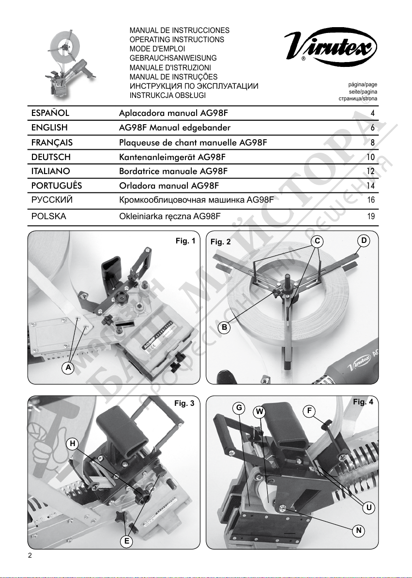
1. Montaje:
Montar el cargador en su alojamiento, mediante los
tornillos A, (Fig. 1).
2. Ajuste:
A) Aflojar el pomo B, (Fig. 2), y retirar la tapa del
cargador D.
B) Ajustar las tres varillas C al diámetro interior del
rollo de cinta.
C) Colocar el rollo de cinta preencolada en el soporte,
situar de nuevo la tapa del cargador D y fijarla mediante
el pomo B.
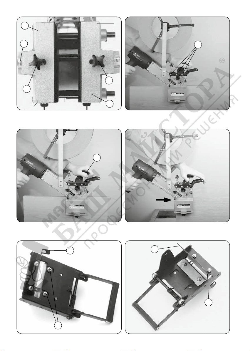
3. REGULACIÓN PASO DE CINTA
1. Aflojar los pomos E, (Fig. 3), y separar los dos cuerpos
para permitir el paso de la cinta.
2. Pasar la cinta por debajo de la varilla anti-retorno F,
(Fig. 4), y a través de las cuchillas U hasta situarla bajo
el rodillo encolador W.
3. Cerrar el cuerpo o lado móvil G mediante el pomo
H, (Fig. 3), a la anchura de la cinta, sin aprisionarla de
modo que vaya guiada, fijándolo en esta posición con
los pomos E, (Fig. 3).
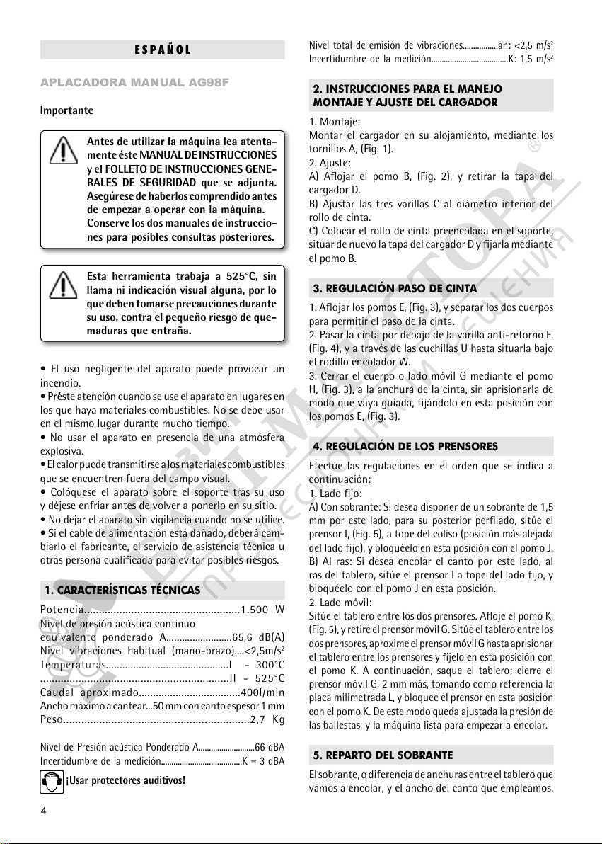
4. REGULACIÓN DE LOS PRENSORES
Efectúe las regulaciones en el orden que se indica a
continuación:
1. Lado fijo:
A) Con sobrante: Si desea disponer de un sobrante de 1,5
mm por este lado, para su posterior perfilado, sitúe el
prensor I, (Fig. 5), a tope del coliso (posición más alejada
del lado fijo), y bloquéelo en esta posición con el pomo J.
B) Al ras: Si desea encolar el canto por este lado, al
ras del tablero, sitúe el prensor I a tope del lado fijo, y
bloquéelo con el pomo J en esta posición.
2. Lado móvil:
Sitúe el tablero entre los dos prensores. Afloje el pomo K,
(Fig. 5), y retire el prensor móvil G. Sitúe el tablero entre los
dos prensores, aproxime el prensor móvil G hasta aprisionar
el tablero entre los prensores y fíjelo en esta posición con
el pomo K. A continuación, saque el tablero; cierre el
prensor móvil G, 2 mm más, tomando como referencia la
placa milimetrada L, y bloquee el prensor en esta posición
con el pomo K. De este modo queda ajustada la presión de
las ballestas, y la máquina lista para empezar a encolar.
5. REPARTO DEL SOBRANTE
El sobrante, o diferencia de anchuras entre el tablero que
vamos a encolar, y el ancho del canto que empleamos,
Page 5

se reparte como sigue:
1. Lado fijo:
El sobrante en este lado será de 1,5 mm o no habrá
sobrante, según hayamos regulado el prensor del lado
fijo. (ver apdo. prensores.) (Fig. 5).
2. Lado móvil:
A) Todo el sobrante quedará en este lado del tablero, si
el prensor del lado fijo se ha regulado "AL RAS". (Fig. 5).
B) Quedará todo el sobrante menos 1,5 mm si el prensor
del lado fijo se ha regulado "CON SOBRANTE". (Fig. 5).
6. ENCOLADO DE CANTOS
1. Situar el aparato al principio del tablero, asegurándose
que la cinta preencolada sobrepasa al menos 1 cm del
extremo del mismo; (Fig. 6).
2. Pulsar el interruptor a la posición I ó II para la puesta
en marcha del calefactor y esperar unos segundos hasta
que alcance la temperatura de régimen y la cola del
canto empiece a fundir.
3. Presionar la cinta preencolada contra el tablero, actuando sobre el pomo M, (Fig. 7), y desplazar la máquina
a lo largo del mismo; (Fig. 6 y 7).
4. Accione la tijera al llegar el prensor al final del tablero
con lo que la cinta quedará cortada, con un sobrante
de 2 cm por este lado y continúe el encolado hasta su
terminación. (Fig. 8).
NOTA. - El calefactor del aparato dispone de dos temperaturas de salida (posiciones I y II del interruptor), 300°C.
Y 525°C. Deberá emplear una u otra según la velocidad
de avance con que encole Vd. y la calidad de la cola de
la cinta preencolada que use.
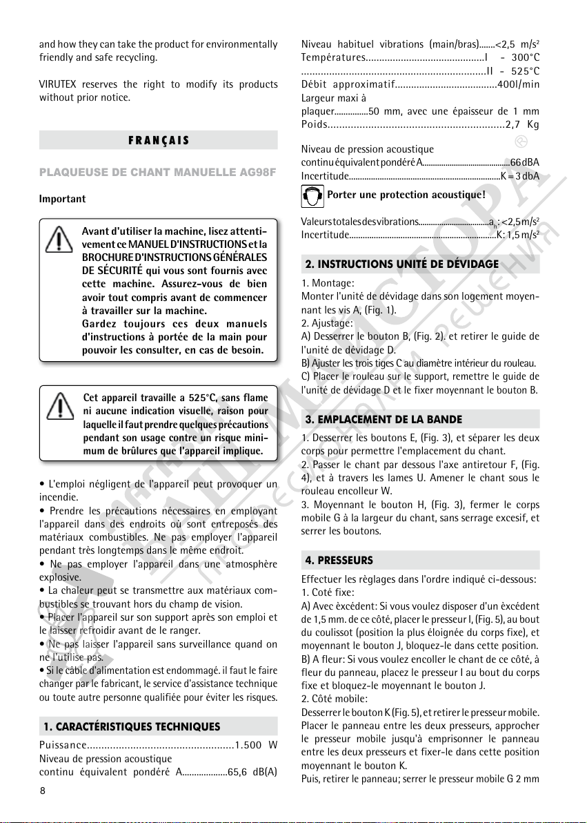
7. MANTENIMIENTO
Desconectar la máquina de la red eléctrica, antes de
efectuar cualquier operación de mantenimiento.
Cambio de cuchillas:
Retirar el tornillo N, (Fig. 4), que sujeta el cuerpo portacuchillas sobre el rodillo encolador y dándole la vuelta
a la máquina, soltar los tres tornillos P, (Fig. 6), que lo
mantienen solidario con el lado fijo.
Separar el cuerpo portacuchillas de la máquina; (Fig. 9).
Retirar el canalizador de cinta Q, (Fig. 9), el deflector R
y la cuchilla trasera S, (Fig. 10).
En la parte superior del cuerpo portacuchillas aparecen las
cabezas de los tornillos T, (Fig. 9) que sujetan la cuchilla
delantera. Aflojar y retirar dichos tornillos con lo que la
cuchilla delantera quedará suelta.
Proceder al cambio de cuchillas, y el armado del conjunto de portacuchillas, en el orden inverso al seguido
para desmontarlo.
9. NIVEL DE RUIDO Y VIBRACIONES
Los niveles de ruido y vibraciones de esta herramienta
eléctrica han sido medidos de acuerdo con la Norma
Europea EN 60745-1 y sirven como base de comparación
con máquinas de semejante aplicación.
El nivel de vibraciones indicado ha sido determinado
para las aplicaciones principales de la herramienta,
y puede ser utilizado como valor de partida para la
evaluación de la exposición al riesgo de las vibraciones.
Sin embargo, el nivel de vibraciones puede llegar a ser
muy diferente al valor declarado en otras condiciones
de aplicación, con otros útiles de trabajo o con un
mantenimiento insuficiente de la herramienta eléctrica
y sus útiles, pudiendo llegar a resultar un valor mucho
más elevado debido a su ciclo de trabajo y modo de uso
de la herramienta eléctrica.
Por tanto, es necesario fijar medidas de seguridad de
protección al usuario contra el efecto de las vibraciones,
como pueden ser mantener la herramienta y útiles de
trabajo en perfecto estado y la organización de los
tiempos de los ciclos de trabajo (tales como tiempos
de marcha con la herramienta bajo carga, y tiempos de
marcha de la herramienta en vacío y sin ser utilizada
realmente ya que la reducción de estos últimos puede
disminuir de forma sustancial el valor total de exposición).
10. GARANTIA
Todas las máquinas electroportátiles VIRUTEX tienen
una garantía válida de 12 meses a partir del día de su
suministro, quedando excluidas todas las manipulaciones
o daños ocasionados por manejos inadecuados o por
desgaste natural de la máquina.
Para cualquier reparación dirigirse al servicio oficial de
asistencia técnica VIRUTEX.
11. RECICLAJE DE LAS
HERRAMIENTAS ELÉCTRICAS
Nunca tire la herramienta eléctrica con el resto de residuos domésticos. Recicle las herramientas, accesorios y
embalajes de forma respetuosa con el medio ambiente.
Respete la normativa vigente de su país.
Aplicable en la Unión Europea y en países europeos con
sistemas de recogida selectiva de residuos:
La presencia de esta marca en el producto o en el
material informativo que lo acompaña, indica que al
finalizar su vida útil no deberá eliminarse junto con
otros residuos domésticos.
8. ACCESORIOS OPCIONALES
5246025- Rodillo inclinado a 4°: pensado para aplacar
cantos sobre planos inclinados de puertas, etc.
5
Page 6

6
Conforme a la Directiva Europea 2002/96/CE los usuarios
pueden contactar con el establecimiento donde adquirie-
ron el producto, o con las autoridades locales pertinentes,
para informarse sobre cómo y dónde pueden llevarlo
para que sea sometido a un reciclaje ecológico y seguro.
VIRUTEX se reserva el derecho de modificar sus productos
sin previo aviso.
ENGLISH
AG98F MANUAL EDGEBANDER
Important
Read these OPERATING INSTRUCTIONS
and the attached GENERAL SAFETY
INSTRUCTIONS LEAFLET carefully before
using the machine. Make sure you have
understood them before operating the
machine for the first time.
Keep both sets of instructions for any
future queries.
This tool works at 525°C=1000°F,
without a flame or any visual indication.
Precautions must be taken against the
slight risk of burns.
• Cereless use of this device can cause fire.
• Pay close attention when using the device in places
where combustible materials are to be found. Do not
use it in the same place over a long period of time.
• Do not use the device in an atmosphere where an
explosion could take place.
• Heat can be transmitted to combustible materials
located outside one's field of vision.
• After use, place the device on its holder and let it cool
down before putting it back in place.
• Do not leave this device unattended when not in use.
• If the feeding cable is damaged, have it replaced by
the manufacturer, technical service or another qualified
person in order to prevent possible hazards.
1. SPECIFICATIONS
Input Power.................................................1.500 W
Equivalent measured continuous
acoustic pressure level A..........................65,6 dB(A)
Normal level of vibrations (hand-arm)..........<2,5m/s
2
Temperatures..................................I - 300°C=570°F
...................................................II - 525°C=1.000°F
Approximate flow-rate................................400l/min
Max. banding width.......50 mm with thickness of 1 mm
Weight...........................................................2,7 Kg
Weighted equivalent continuous
acoustic pressure level A..................................................66 dBA
Uncertainty...................................................................K = 3 dbA
Wear ear protection!
Vibration total values...............................................ah:<2,5m/s
2
Uncertainty....................................................................K: 1.5 m/s
2
2. INSTRUCTIONS FOR HANDLING, ASSEMBLING
AND ADJUSTING THE LOADER
1. Assembly:
Fit the loader in its housing using, screws A, (Fig. 1).
2. Adjustment:
A) Loosen knob B, (Fig. 2), and remove the cover from
the loader D.
B) Adjust the Three rods C to the internal diameter of
the strip roll.
C) Place the pre-glued strip roll in the support, replace
the cover to D and fix it using knob B.
3. ADJUSTING MOVEMENT OF THE STRIP
1. Loosen knobs E, (Fig. 3), and separate the two bodies
to allow the strip to pass.
2. Pass the strip under the anti-return rod F, (Fig. 4),
and through blades U until it is under glueing roller W.
3. Use knob H to adjust the moving part G, (Fig. 3), to the
width of the strip. Do not trap it. When it is guided, secure
it in this position with knobs E, (Fig. 3).
4. ADJUSTING THE CLAMPS
Carry out the adjustments in the order given below:
1. Fixed side:
A) With an overlap: For an overlap of 1.5 mm on this
side for later trimming, place clamp I, (Fig. 5), at the
end of the slotted lever (position furthest away from
the fixed body), and lock it in this position with knob J.
B) Flush with the board: If you wish to glue the edge on
this side, flush with the board, place clamp I at the end
of the fixed side and lock it in this position with knob J.
2. Moving side:
Place the panel between the two clamps. Loosen knob
K, (Fig. 5), and remove mobile clamp G. Place the panel
between the two clamps, bring mobile clamp G up until
the panel is caught between the clamps and fix in this
position with knob K. Then remove the panel; close
moving clamp G by another 2 mm, taking scaled plate
L as a reference, and lock the clamp in this position with
knob K. In this way, the pressure of the leaf springs is
adjusted, and the machine is ready to use.
Page 7

5. OVERLAP DISTRIBUTION
The overlap, or the difference in width between the
panel to be edge banded and the width of the strip
being used, is distributed as follows:
1. Fixed side:
The overlap on this side will be 1.5 mm, or there will
be no overlap, depending on the way the clamp on the
fixed side has been adjusted (see clamps section) (Fig. 5).
2. Moving side:
A) All the overlap will remain on this side of the panel,
if the fixed side clamp I has been adjusted “FLUSH WITH
THE BOARD”. (Fig. 5).
B) If the fixed side clamp has been adjusted “WITH AN
OVERLAP”, all the overlap except for 1.5 mm (Fig. 5)
will remain.
6. EDGE BANDING
1. Place the tool at the beginning of the panel, making
sure that the pre-glued strip exceeds the panel end by
at least 1 cm: (Fig. 6).
2. Set the switch to position I or II to start up the heater
and wait for a few seconds until the rated temperature
is reached and the strip glue starts to melt.
3. Press the pre-glued strip against the panel, by pushing
on knob M, (Fig. 7), and move the machine along the
panel; (Figs. 6 and 7).
4. Operate the cutting lever when the clamp reaches the
end of the panel, with an overlap of 2 cm on this side
and continue edging until the end; (Fig. 8).
NOTE. - The heater has two output temperatures (switch
positions I and II): 300°C and 525°C (570°F and 1000°F).
Use one or the other depending on the advance speed
at which you are edging and the quality of the glue on
the pre-glued strip you are using
7. MAINTENANCE
Before performing any maintenance operation, disconnect machine from power source.
Changing blades:
Remove screw N, (Fig. 4), which secures the blade block
to the gluing roller. Turn the machine over and loosen
the three screws P, (Fig. 6), that hold it to the fixed side.
Separate the blade block from the machine; (Fig.9).
Remove strip guide Q, (Fig. 9), deflector R and rear
blade S, (Fig. 10).
The heads of screws T, (Fig. 9) securing the front blade
can be seen at the top of the blade block. Loosen and
remove these screws, releasing the front blade.
Change the blades and re-assemble the blade block
in the opposite order to that given for dismantling it.
8. OPTIONAL ACCESSORIES
5246025- Inclined roller (4°), for edging inclined
doors, etc,
9. NOISE AND VIBRATION LEVEL
The noise and vibration levels of this device have been
measured in accordance with European standard EN
60745-1 and serve as a basis for comparison with other
machines with similar applications.
The indicated vibration level has been determined for
the device’s main applications and may be used as an
initial value for evaluating the risk presented by exposure to vibrations. However, vibrations may reach levels
that are quite different from the declared value under
other application conditions, with other tools or with
insufficient maintenance of the electrical device or its
accessories, reaching a much higher value as a result
of the work cycle or the manner in which the electrical
device is used.
Therefore, it is necessary to establish safety measures
to protect the user from the effects of vibrations, such
as maintaining both the device and its tools in perfect
condition and organising the duration of work cycles
(such as operating times when the machine is subjected
to loads, and operating times when working with no-load,
in effect, not in use, as reducing the latter may have a
considerable effect upon the overall ex
10. WARRANTY
All VIRUTEX power tools are guaranteed for 12 months
from the date of purchase, excluding any damage which
is a result of incorrect use or fo natural wear and tear
on the machine. All repairs should be carried out by the
official VIRUTEX technical assistance service.
11. RECYCLING ELECTRICAL EQUIPMENT
Never dispose of electrical equipment with domestic waste. Recycle equipment, accessories and packaging in ways
that minimise any adverse effect on the environment.
Comply with the current regulations in your country.
Applicable in the European Union and in European
countries with selective waste collection systems:
If this symbol appears on the product or in the accompanying information, at the end of the product's useful
life it must not be disposed of with other domestic waste.
In accordance with European Directive 2002/96/EC, users
may contact the establishment where they purchased the
product or the relevant local authority to find out where
7
Page 8
8
and how they can take the product for environmentally
friendly and safe recycling.
VIRUTEX reserves the right to modify its products
without prior notice.
FRANÇAIS
PLAQUEUSE DE CHANT MANUELLE AG98F
Important
Avant d'utiliser la machine, lisez attenti-
vement ce MANUEL D'INSTRUCTIONS et la
BROCHURE D'INSTRUCTIONS GÉNÉRALES
DE SÉCURITÉ qui vous sont fournis avec
cette machine. Assurez-vous de bien
avoir tout compris avant de commencer
à travailler sur la machine.
Gardez toujours ces deux manuels
d'instructions à portée de la main pour
pouvoir les consulter, en cas de besoin.
Cet appareil travaille a 525°C, sans flame
ni aucune indication visuelle, raison pour
laquelle il faut prendre quelques précautions
pendant son usage contre un risque mini-
mum de brûlures que l'appareil implique.
• L'emploi négligent de l'appareil peut provoquer un
incendie.
• Prendre les précautions nécessaires en employant
l'appareil dans des endroits où sont entreposés des
matériaux combustibles. Ne pas employer l'appareil
pendant très longtemps dans le même endroit.
• Ne pas employer l'appareil dans une atmosphère
explosive.
• La chaleur peut se transmettre aux matériaux com-
bustibles se trouvant hors du champ de vision.
• Placer l'appareil sur son support après son emploi et
le laisser refroidir avant de le ranger.
• Ne pas laisser l'appareil sans surveillance quand on
ne l'utilise pas.
• Si le câble d'alimentation est endommagé. il faut le faire
changer par le fabricant, le service d'assistance technique
ou toute autre personne qualifiée pour éviter les risques.
1. CARACTÉRISTIQUES TECHNIQUES
Puissance...................................................1.500 W
Niveau de pression acoustique
continu équivalent pondéré A...................65,6 dB(A)
Niveau habituel vibrations (main/bras).......<2,5 m/s
2
Températures............................................I - 300°C
..................................................................II - 525°C
Débit approximatif......................................400l/min
Largeur maxi à
plaquer...............50 mm, avec une épaisseur de 1 mm
Poids.............................................................2,7 Kg
Niveau de pression acoustique
continu équivalent pondéré A..........................................66 dBA
Incertitude.....................................................................K = 3 dbA
Porter une protection acoustique!
Valeurs totales des vibrations..................................ah: <2,5 m/s
2
Incertitude..................................................................K: 1,5 m/s
2
2. INSTRUCTIONS UNITÉ DE DÉVIDAGE
1. Montage:
Monter l'unité de dévidage dans son logement moyen-
nant les vis A, (Fig. 1).
2. Ajustage:
A) Desserrer le bouton B, (Fig. 2). et retirer le guide de
l'unité de dévidage D.
B) Ajuster les trois tiges C au diamètre intérieur du rouleau.
C) Placer le rouleau sur le support, remettre le guide de
l'unité de dévidage D et le fixer moyennant le bouton B.
3. EMPLACEMENT DE LA BANDE
1. Desserrer les boutons E, (Fig. 3), et séparer les deux
corps pour permettre l'emplacement du chant.
2. Passer le chant par dessous l'axe antiretour F, (Fig.
4), et à travers les lames U. Amener le chant sous le
rouleau encolleur W.
3. Moyennant le bouton H, (Fig. 3), fermer le corps
mobile G à la largeur du chant, sans serrage excesif, et
serrer les boutons.
4. PRESSEURS
Effectuer les règlages dans l'ordre indiqué ci-dessous:
1. Coté fixe:
A) Avec èxcédent: Si vous voulez disposer d'un èxcédent
de 1,5 mm. de ce côté, placer le presseur I, (Fig. 5), au bout
du coulissot (position la plus éloignée du corps fixe), et
moyennant le bouton J, bloquez-le dans cette position.
B) A fleur: Si vous voulez encoller le chant de ce côté, à
fleur du panneau, placez le presseur I au bout du corps
fixe et bloquez-le moyennant le bouton J.
2. Côté mobile:
Desserrer le bouton K (Fig. 5), et retirer le presseur mobile.
Placer le panneau entre les deux presseurs, approcher
le presseur mobile jusqu'à emprisonner le panneau
entre les deux presseurs et fixer-le dans cette position
moyennant le bouton K.
Puis, retirer le panneau; serrer le presseur mobile G 2 mm
Page 9

de plus, en prenant comme référence la plaque milimitrée
L et bloquer le presseur dans cette position moyennant le
bouton K. De cette façon, on ajuste la pression des lames
de ressort et l'appareil est prêt pour commencer à encoller.
5. DISTRIBUTION DE L'EXCEDENT
L'èxcédent ou différence de largeur entre le panneau
que nous allons encoller, et le chant que l'on utilise, se
distribue de la manière suivante:
1. Coté fixe:
A ce côté, l'èxcédent sera de 1,5 mm ou il n'y aura pas
d'èxcédent selon que nous ayons règlé le presseur du
côté fixe. (Voir paragraphe des presseurs); (Fig. 5).
2. Coté mobile:
A) Tout l'èxcédent restera à ce côté du panneau, si le
presseur du côté fixe a été règlé "A FLEUR"; (Fig. 5).
B) Tout l'èxcédent restera à ce côté du panneau moins
1,5 mm si le presseur du côté fixe a été règlé "AVEC
EXCEDENT"; (Fig. 5).
6. ENCOLLAGE DES CHANTS
1. Placer l'appareil au début du panneau en nous assurant
que le chant préencollé dépasse d'au moins 1 cm; (Fig. 6).
2. Pousser l'interrupteur à la position I ou II pour la
mise en marche de l'unité de chauffage et attendre
quelques segondes jusqu'à ce que la colle du chant
commence à fondre.
3. Presser le chant préencollé contre le panneau en
vous appuyant sur le pommeau M, (Fig. 7), et déplacer
l'appareil tout le long du panneau; (Fig. 6 et 7).
4. Pour couper le chant, faire fonctionner les ciseaux
quand le presseur arrive au bout du panneau, et continuer
l'encollage jusqu'au bout; (Fig. 8).
NOTE. - L'unité de chauffage de l'appareil dispose de deux
températures de sortie (positions I et II de l'interrupteur),
300°C. et 525°C. Vous devrez utiliser l'une ou l'autre
selon la vitesse d'avancement et la qualité de la colle.
7. ENTRETIEN
Débranchez la machine du reseau electrique, avant toute
opération d'entretien.
Changement des lames:
Retirer la vis N, (Fig. 4), de fixation du corps porte-lames
placée sur le rouleau encolleur et en tournant l'appareil,
lâcher les trois vis P, (Fig. 6), qui l'attachent au corps fixe.
Séparer le corps porte-lames de l'appareil.
Retirer le canaliseur du chant Q, (Fig. 9), le déflecteur
R et la lame postérieure S, (Fig. 10).
Sur la partie supérieure du corps porte-lames sont placées
les vis T, (Fig. 9), qui maintiennent la lame de devant.
Desserrer et retirer ces vis.
Procéder au changement des lames et au montage du
corps porte-lames en suivant l'ordre inverse.
8. ACCESSOIRES EN OPTION
5246025- Rouleau incliné à 4°, pour des chants des portes
9. NIVEAU DE BRUIT ET DE VIBRATIONS
Les niveaux de bruit et de vibrations de cet appareil
électrique ont été mesurés conformément à la norme
européenne EN 60745-1 et font office de base de comparaison avec des machines aux applications semblables.
Le niveau de vibrations indiqué a été déterminé pour
les principales applications de l’appareil, et il peut être
pris comme valeur de base pour l’évaluation du risque
lié à l’exposition aux vibrations. Toutefois, dans d’autres
conditions d’application, avec d’autres outils de travail
ou lorsque l’entretien de l’appareil électrique et de
ses outils est insuffisant, il peut arriver que le niveau
de vibrations soit très différent de la valeur déclarée,
voire même beaucoup plus élevé en raison du cycle de
travail et du mode d'utilisation de l'appareil électrique.
Il est donc nécessaire de fixer des mesures de sécurité
pour protéger l'utilisateur contre les effets des vibrations,
notamment garder l’appareil et les outils de travail en
parfait état et organiser les temps des cycles de travail
(temps de fonctionnement avec l’appareil en service,
temps de fonctionnement avec l’appareil à vide, sans être
utilisé réellement), car la diminution de ces temps peut
réduire substantiellement la valeur totale d’exposition.
10. GARANTIE
Tous les machines électro-portatives VIRUTEX ont une
garantie valable 12 mois à partir de la date d'achat, en
étant exclus toutes manipulations ou dommages causés
par des maniements inadéquats ou par l'usure naturelle
de la machine. Pour toute réparation, s'adresser au service
officiel d'assistance technique VIRUTEX.
11. RECYCLAGE DES OUTILS ÉLECTRIQUES
Ne jetez jamais un outil électrique avec le reste des déchets ménagers. Recyclez les outils, les accessoires et les
emballages dans le respect de l'environnement. Veuillez
respecter la réglementation en vigueur dans votre pays.
Applicable au sein de l'Union Européenne et dans les pays
européens dotés de centres de tri sélectif des déchets:
Ce symbole présent sur le produit ou sur la documentation informative qui l'accompagne, indique qu'en fin
de vie, ce produit ne doit en aucun cas être éliminé avec
le reste des déchets ménagers.
Conformément à la directive européenne 2002/96/CE,
9
Page 10
10
tout utilisateur peut contacter l'établissement dans
lequel il a acheté le produit, ou les autorités locales
compétentes, pour se renseigner sur la façon d’éliminer le
produit et le lieu où il doit être déposé pour être soumis
à un recyclage écologique, en toute sécurité.
VIRUTEX se réserve le droit de modifier ses produits
sans avis préalable.
DEUTSCH
KANTENANLEIMGERÄT AG98F
Wichtiger Hinweis
Lesen Sie bitte vor Benutzung der Maschine
die beiliegende GEBRAUCHSANWEISUNG und
die ALLGEMEINEN SICHERHEITSHINWEISE
sorgfältig durch.
Stellen Sie sicher, dass Sie sowohl die Ge-
brauchsanweisung als auch die allgemeinen
Sicherheitshinweise verstanden haben, bevor
Sie die Maschine bedienen. Bewahren Sie
beide Gebrauchsanweisungen zum späteren
Nachschlagen auf.
Dieses Werkzeug arbeitet bei 525°C ohne
Flamme oder sonstige sichtbare Anzeichen
auf Wärme. Daher müssen bei seiner
Benutzung Vorsichtsmaßnahmen gegen
das geringe Risiko von Verbrennungen
getroffen werden.
• Die unachtsame Verwendung des Geräts kann einen
Brand verursachen.
• Aufmerksamkeit ist geboten, wenn das Gerät an einem
Ort verwendet wird, wo sich brennbare Materialien
befinden. Das Gerät darf nicht lange an der gleichen
Stelle verwendet werden.
• Verwenden Sie das Gerät nicht in einer explosiven
Atmosphäre.
• Die Wärme kann sich auf brennbare Materialien
außerhalb des Blickfelds übertragen.
• Legen Sie das Gerät nach dem Gebrauch auf der Au-
flage ab und lassen Sie es abkühlen, bevor es an seinen
Platz gestellt wird.
• Lassen Sie das Gerät bei Arbeitsunterbrechung nicht
unbeaufsichtigt.
• Ist das Netzkabel beschädigt, muss es vom Hersteller,
dem technischen Kundendienst oder einer anderen qua-
lifizierten Person ausgewechselt werden, um mögliche
Risiken zu vermeiden.
1. TECHNISCHE DATEN
Leistung................................................1.500 W
Umgerechnetes akustisches
Dauerdruckpegeläquivalent A................65,6 dB(A)
Normaler Schwingungspegel (Hand-Arm)..<2,5 m/s
2
Temperaturen.............................................I - 300°C
..................................................................II - 525°C
Förderrate ca.............................................400 l/min
Max. Bandbreite........50 mm bei einer Stärke von 1 mm
Gewicht.........................................................2,7 Kg
Gewichteter akustischer Dauerdruckpegel A.............66 dBA
Unsicherheit..................................................................K = 3 dBA
Gehörschutz tragen!
Schwingungsgesamtwerte....................................ah: <2,5 m/s
2
Unsicherheit.............................................................K = 1,5 m/s
2
2. BEDIENUNGSANLEITUNG - ANBRINGEN
UNDEINSTELLEN DER LADEEINHEIT
1. Montage:
Montieren Sie die Ladeeinheit mit den Schrauben A in
ihrer Lagerung (Abb. 1).
2. Einstellung:
A) Lockern Sie den Knauf B (Abb. 2) und nehmen Sie die
Abdeckung der Ladeeinheit ab.
B) Stellen Sie die drei Stäbe C auf den Innendurchmesser
der Bandrolle ein.
C) Bringen Sie die Rolle mit vorgeleimtem Band an der
Halterung an, setzen Sie die Abdeckung der Ladeeinheit
D wieder auf und befestigen Sie sie mit dem Knauf B.
3. EINSTELLUNG DES BANDDURCHLAUFS
1. Lockern Sie die Knäufe E (Abb. 3) und trennen Sie
die beiden Körper voneinander, damit das Band durch-
laufen kann.
2. Führen Sie das Band unter der Rücklaufsperrleiste (Abb.
4) und über die Messer U bis unter die Leimrolle W durch.
3. Schließen Sie den Körper bzw. die bewegliche Seite G
mit dem Knauf H (Abb. 3) auf der Höhe des Bands, damit
das Band richtig durchgeführt wird, aber ohne es zu sehr
einzuklemmen. Stellen Sie es in dieser Position mit den
Knäufen E fest (Abb. 3).
4. EINSTELLUNG DER PRESSVORRICHTUNGEN
Gehen Sie bei der Einstellung in der gleichen Reihenfolge
wie unten beschrieben vor:
1. Feststehende Seite:
A) Mit Überstand:
Wenn Sie auf dieser Seite einen Überstand von 1,5 mm
zum späteren Profilieren wünschen, platzieren Sie die
Pressvorrichtung I (Abb. 5) am Führungsanschlag (in der
von der feststehenden Seite am weitesten entfernten
Page 11

Position). Blockieren Sie diese Position mit dem Knauf J.
B) Bündig:
Wenn Sie die Kante auf dieser Seite bündig mit dem Brett
anleimen möchten, platzieren Sie die Pressvorrichtung
I am Anschlag der feststehenden Seite und blockieren
Sie sie mit dem Knauf J in dieser Position.
2. Bewegliche Seite:
Legen Sie das Brett zwischen die beiden Pressvorrichtungen. Lockern Sie den Knauf K (Abb. 5) und nehmen die
bewegliche Pressvorrichtung G ab. Legen Sie das Brett
zwischen die beiden Pressvorrichtungen, bringen Sie die
bewegliche Pressvorrichtung G solange näher heran, bis
Sie das Brett zwischen den Pressvorrichtungen eingeklemmt haben. Befestigen Sie es in dieser Position mit
dem Knauf K. Nehmen Sie dann das Brett heraus und
schließen die bewegliche Pressvorrichtung G noch 2 mm.
Nehmen Sie dabei die Platte mit Millimetereinteilung
L zu Hilfe. Blockieren Sie die Pressvorrichtung in dieser
Position mit dem Knauf K. So wird der Druck der Federn
eingestellt und die Maschine ist fertig zum Anleimen.
5. VERTEILUNG DES ÜBERSTANDS
Der Überstand, d.h. der Breitenunterschied zwischen
dem zu verleimenden Brett und der verwendeten Kante,
wird wie folgt verteilt:
1. Feststehende Seite:
Auf dieser Seite haben wir einen Überstand von 1,5 mm
oder gar keinen, je nachdem wie die Pressvorrichtung der
feststehenden Seite eingestellt wurde (siehe Abschnitt
Pressvorrichtungen). (Abb. 5).
2. Bewegliche Seite:
A)Wenn die Pressvorrichtung der feststehenden Seite
"BÜNDIG" eingestellt wurde, haben wir den ganzen
Überstand auf dieser Seite. (Abb. 5).
B)Wenn die Pressvorrichtung der feststehenden Seite
auf "MIT ÜBERSTAND" eingestellt wurde, haben wir auf
dieser Seite den ganzen Überstand minus 1,5 mm (Abb. 5).
6. ANLEIMEN DER KANTEN
Platzieren Sie das Gerät am Anfang des Bretts und stellen
Sie sicher, dass das vorgeleimte Band mindestens 1 cm
übersteht (Abb. 6).
2. Stellen Sie den Schalter auf I oder II, um die Heizvorrichtung in Gang zu setzen und warten Sie einige
Minuten, bis die Betriebstemperatur erreicht ist und der
Leim an der Kante zu schmelzen beginnt.
3. Drücken Sie das vorgeleimte Band gegen das Brett,
indem Sie den Knauf M (Abb. 7) betätigen und führen
Sie die Maschine am Brett entlang (Abb. 6 und 7).
4. Wenn die Pressvorrichtung am Ende des Bretts angekommen ist, betätigen Sie die Schere, wodurch das
Band an dieser Seite mit einem Überstand von 2 cm
abgeschnitten wird. Setzen Sie das Anleimen bis zum
Ende fort (Abb. 8).
HINWEIS.- Die Heizvorrichtung an diesem Gerät hat
zwei Ausgangstemperaturen (Positionen I und II des
Schalters): 300 °C und 525 °C. Arbeiten Sie mit der einen
oder anderen Temperatur, je nachdem wie schnell Sie
anleimen und je nach Qualität des Leims am Band, mit
dem Sie arbeiten.
7. WARTUNG
Ziehen Sie vor allen Wartungsarbeiten den Netzstecker.
Auswechseln der Messer:
Schrauben Sie die Schraube N (Abb. 4), die den Messerhalterkörper über der Anleimrolle befestigt, ab. Drehen Sie die
Maschine um und lösen Sie die drei Schrauben P (Abb. 6),
die die Rolle mit der feststehenden Seite zusammenhalten.
Nehmen Sie den Messerhalterkörper von der Maschine
ab (Abb. 9).
Entfernen Sie den Bandleiter Q (Abb. 9), den Abweiser
R und das hintere Messer S (Abb. 10).
Oben am Messerhalterkörper sieht man die Köpfe der
Schrauben T (Abb. 9), mit denen das vordere Messer
befestigt ist. Lockern Sie diese Schrauben und nehmen Sie
sie ab, sodass das vordere Messer gelöst wird. Tauschen
Sie die Messer aus und setzen Sie den Messerhalterkörper
in umgekehrter Reihenfolge wie beim Auseinanderbauen
wieder zusammen.
8. EXTRA-ZUBEHÖR
5246025- Geneigte Laufrolle (4°) für Türen usw.
9. GERÄUSCHPEGEL UND VIBRATIONSSTÄRKE
Die Lärm- und Vibrationswerte dieses Elektrowerkzeugs
wurden in Übereinstimmung mit der europäischen
Norm EN 60745-1 gemessen und dienen als
Vergleichsgrundlage bei Maschinen für ähnliche
Anwendungen.
Der angegebene Vibrationspegel wurde für die
wesentlichen Einsatzzwecke des Werkzeugs ermittelt
und kann bei der Beurteilung der Gefahren durch
die Aussetzung unter Vibrationen als Ausgangswert
benutzt werden. Die Vibrationswerte können sich
jedoch unter anderen Einsatzbedingungen, mit anderen
Arbeitswerkzeugen oder bei einer ungenügenden Wartung
des Elektrowerkzeugs oder seiner Werkzeuge stark vom
angegebenen Wert unterscheiden und aufgrund des
Arbeitszyklus und der Einsatzweise des Elektrowerkzeugs
einen bedeutend höheren Wert aufweisen.
Es ist daher erforderlich, Sicherheitsmaßnahmen zum
Schutz des Anwenders vor den Vibrationen festzulegen.
Dazu können die Aufrechterhaltung des einwandfreien
Zustands des Werkzeugs und der Arbeitsutensilien
sowie die Festlegung der Zeiten der Arbeitszyklen
gehören (wie Laufzeiten des Werkzeugs unter Last und
im Leerlauf, ohne tatsächlich eingesetzt zu werden,
wodurch die Gesamtzeit der Vibrationsauswirkungen
bedeutend verringert werden kann).
11
Page 12

12
10. GARANTIE
Alle Elektrowerkzeuge von VIRUTEX habe eine Garantie von
12 Monaten ab dem Lieferdatum. Hiervon ausgeschlossen sind
alle Eingriffe oder Schäden aufgrund von unsachgemäßem
Gebrauch oder natürlicher Abnutzung des Geräts.
Wenden Sie sich im Falle einer Reparatur immer an den
zugelassenen Kundendienst von VIRUTEX.
11. RECYCELN VON ELEKTROWERKZEUGEN
Entsorgen Sie Elektrowerkzeuge nie zusammen mit den
restlichen Hausabfällen. Recyceln Sie die Werkzeuge, das
Zubehör und die Verpackungen umweltgerecht. Beachten
Sie die geltenden Rechtsvorschriften Ihres Landes.
Anwendbar in der Europäischen Union und in Ländern
mit Mülltrennsystemen:
Das Vorhandensein dieser Kennzeichnung auf dem
Produkt oder im beiliegenden Informationsmaterial
bedeutet, dass das Produkt nach seiner Nutzungsdauer
nicht zusammen mit anderen Haushaltsabfällen entsorgt
werden darf.
Gemäß der EU-Richtlinie 2002/96/EG können sich die
Nutzer an die Verkaufsstelle, bei der sie das Produkt
erworben haben, oder an die zuständigen örtlichen
Behörden wenden, um in Erfahrung zu bringen, wohin
Sie das Produkt zur umweltgerechten und sicheren
Entsorgung bringen können.
VIRUTEX behält sich das Recht vor, die Produkte ohne
vorherige Ankündigung zu verändern.
ITALIANO
BORDATRICE MANUALE AG98F
Importante
Prima di utilizzare la macchina, leggere
attentamente questo MANUALE DI IS-
TRUZIONI e il PROSPETTO DELLE NORME
GENERALI DI SICUREZZA allegato. Non
cominciate a lavorare con la macchina
se non si è sicuri di avere compreso in-
tegralmente il loro contenuto.
Conservare entrambi i manuali per
eventuali consultazioni successive.
Questo utensile lavora a una temperatura
di 525°C, senza fiamma o altro segnale
visibile. Durante l'uso sarà quindi neces-
sario prendere le dovute precauzioni per
prevenire il rischio di ustioni.
• L'utilizzo negligente dell'apparecchio può causare
un incendio.
• Prestare attenzione quando si utilizza l'apparecchio in
luoghi in cui vi sono materiali combustibili. Non utilizzare
nello stesso punto per lungo tempo.
• Non utilizzare l'apparecchio in presenza di atmosfera
esplosiva.
• Il calore può essere trasmesso ai materiali combustibili
che si trovano fuori dal campo visivo.
• Posizionare l'apparecchio sul suo supporto dopo averlo
utilizzato e farlo raffreddare prima di rimetterlo al suo posto.
• Non lasciare l'apparecchio incustodito quando non
viene utilizzato.
• Se il cavo di alimentazione è danneggiato, deve essere
sostituito dal costruttore, dal servizio di assistenza tecnica
o comunque da una persona con qualifica similare, in
modo da prevenire ogni rischio.
1. CARATTERISTICHE TECNICHE
Potenza.....................................................1.500 W
Livello di pressione acustica continuo
equivalente ponderato A..........................65,6 dB(A)
Livello di vibrazioni
abituale (mano-braccio)........................<2,5 m/s
2
Temperature...............................................I - 300 °C
.................................................................II - 525 °C
Portata approssimativa..............................400 l/min
Spessore massimo
di bordatura.................50 mm con 1 mm di spessore
Peso..............................................................2,7 Kg
Livello di pressione acustica continuo equivalente
ponderato A.......................................................................66 dBA
Incertezza della misura..................................................K = 3 dBA
Usare la protezione acustica!
Valori totali delle oscillazioni..................................ah: <2,5 m/s
2
Incertezza della misura...............................................K: 1,5 m/s
2
2. ISTRUZIONI PER L'USO, IL MONTAGGIO
E LA REGOLAZIONE DEL CARICATORE
1. Montaggio:
Montare il caricatore nell'apposita sede tramite le viti
A. (Fig. 1).
2. Regolazione:
A) Allentare la manopola B, (Fig. 2), e togliere il coperchio
del caricatore D.
Page 13

B) Regolare le tre asticelle C secondo il diametro interno
del rotolo di bordo.
C) Sistemare il rotolo di bordo preincollato sul supporto,
rimettere il coperchio del caricatore D e fissarlo tramite
la manopola B.
3. REGOLAZIONE DEL PASSAGGIO
DEL NASTRO
1. Allentare le manopole E, (Fig. 3), e separare le due
parti per permettere il passaggio del bordo.
2. Far passare il bordo sotto l'asticella antiritorno F,
(Fig. 4), e attraverso le lame U, fino a sistemarlo sotto
il rullo incollatore W.
3. Chiudere la parte mobile G tramite la manopola H,
(Fig. 3), secondo la larghezza del bordo, senza premerlo,
in modo che serva da guida, quindi fissarlo in questa
posizione con le manopole E (Fig. 3).
4. REGOLAZIONE DEI PRESSORI
Eseguire le regolazioni nell'ordine indicato qui di seguito:
1. Lato fisso:
A) Con eccedenza: Se si desidera che avanzi una sporgenza
di 1,5 mm da questo lato per poi profilarla, sistemare il
pressore I, (Fig. 5), al limite della guida (nella posizione
più lontana dal lato fisso) e bloccarlo in questa posizione
con la manopola J.
B) Raso: Se si desidera incollare il bordo da questo lato, al
livello del pannello, sistemare il pressore I all'estremità del
lato fisso e bloccarlo in questa posizione con la manopola J.
2. Lato mobile:
Sistemare il pannello tra i due pressori. Allentare la manopola K, (Fig. 5), e togliere il pressoio mobile G. Sistemare
il pannello tra i due pressoi, avvicinare il pressore mobile
G fino a bloccare il pannello tra i due pressori e fissarlo
in questa posizione tramite la manopola K.
Successivamente togliere il pannello, chiudere il pressore mobile G ancora 2 mm, prendendo come riscontro
la placchetta millimetrata L, e bloccare il pressore in
questa posizione con la manopola K. In questo modo
la pressione delle balestre è calibrata e la macchina è
pronta per l'uso.
5. DISTRIBUZIONE DELL’ECCEDENZA
L’eccedenza (o la differenza) tra la larghezza del pannello
da incollare e quella del bordo utilizzato, si distribuisce
come segue:
1. Lato fisso:
L’eccedenza in questo lato sarà di 1,5 mm, oppure non
esisterà, a seconda di come è stato regolato il pressore
del lato fisso. (Vedere capitolo pressore). (Fig. 5).
2. Lato mobile:
A) Tutta l’eccedenza sarà da questa parte del pannello, se il
pressore del lato fisso è stato regolato in posizione "RASO".
(Fig. 5).
B) Resterà tutta l’eccedenza, meno 1,5 mm, se il pressore
del lato fisso è stato regolato "CON ECCEDENZA". (Fig. 5).
6. INCOLLATURA BORDI
1. Sistemare la macchina all'inizio del pannello, verificando che il bordo preincollato sia di almeno 1 cm più
lungo del pannello. (Fig. 6).
2. Premere l'interruttore mettendolo in posizione I oppure
II per azionare il riscaldatore, e attendere alcuni secondi
finché raggiunge la temperatura di esercizio e la colla
del bordo comincia a fondersi.
3. Premere il bordo preincollato contro il pannello agendo
sulla manopola M, (Fig. 7), e fare scorrere la macchina
lungo il pannello. (Fig. 6 e 7).
4. Azionare la forbice quando il pressore arriva alla fine del
pannello (il bordo verrà tagliato con un’eccedenza di 2 cm da
questo lato) e continuare l'incollatura fino alla fine. (Fig.8).
N.B.: Il riscaldatore della macchina utensile è dotato di due temperature di uscita (posizioni I e II
dell'interruttore): 300°C e 525°C. Scegliere una o l'altra
secondo la velocità di avanzamento durante l'incollatura
e la qualità della colla del bordo preincollato utilizzato.
7. MANUTENZIONE
Prima di eseguire qualsiasi operazione di manutenzione,
scollegare la macchina dalla rete elettrica.
Cambio delle lame:
Togliere la vite N, (Fig. 4), che mantiene il gruppo
portalame pressato contro il rullo incollatore, girare
la macchina ed estrarre le tre viti P, (Fig. 6), che lo
mantengono solidale al lato fisso.
Separare il gruppo portalame dalla macchina. (Fig. 9).
Togliere il canalizzatore del bordo Q, (Fig. 9), il deflettore
R e la lama posteriore S, (Fig. 10).
Nella parte superiore del gruppo portalame sono visibili le
teste delle viti T, (Fig. 9), che fissano la lama anteriore. Allentare e togliere queste viti per rimuovere la lama anteriore.
Cambiare le lame e l'armatura del gruppo portalame
nell'ordine inverso rispetto a quello seguito per smontarlo.
8. ACCESSORI A RICHIESTA
5246025- Rullo a 4° per porte, ecc
9. LIVELLI DE RUMORE E DI VIBRAZIONI
I livelli di rumore e vibrazioni di questo apparato
elettrico sono stati misurati in conformità con la
Norma Europea EN 60745-1 e fungono da base di
confronto con macchine per applicazioni simili.
Il livello di vibrazioni indicato è stato determinato
per le principali applicazioni dell’apparato e può
essere utilizzato come punto di partenza per la
valutazione dell’esposizione al rischio delle vibrazioni.
Ciononostante, il livello di vibrazioni può variare
13
Page 14

14
notevolmente rispetto al valore dichiarato in altre
condizioni di applicazione, con altri strumenti di lavoro
o in caso di manutenzione insufficiente dell’apparato
elettrico e dei suoi strumenti, e può aumentare
notevolmente come conseguenza del ciclo di lavoro e
del modo d’uso dell’apparato elettrico.
Pertanto è necessario stabilire misure di sicurezza per
la protezione dell’utente dall’effetto delle vibrazioni,
ad esempio mantenendo l’apparato e gli strumenti
di lavoro in perfetto stato e pianificando i tempi dei
cicli lavorativi (ad esempio i tempi di funzionamento
dell’apparato sotto carico e i tempi di funzionamento
a vuoto quando l'apparato non viene realmente
utilizzato, dato che la riduzione di questi ultimi
può ridurre in modo sostanziale il valore totale
dell’esposizione).
10. GARANZIA
Tutte le macchine elettroportatili VIRUTEX hanno una
garanzia di 12 mesi valida a partire della data di consegna,
con l'esclusione di tutte le manipolazioni o danni derivanti
da un uso inadeguato o dall'usura normale della macchina.
Per qualunque riparazione rivolgersi al servizio autoriz-
zato di assistenza tecnica VIRUTEX.
11. SMALTIMENTO DI APPARECCHI ELETTRICI
Non buttare mai gli apparecchi elettrici con il resto dei
rifiuti domestici. Smaltire gli apparecchi, gli accessori
e gli imballaggi nel rispetto dell'ambiente. Rispettare la
normativa vigente nazionale.
Applicabile nell’Unione Europea e nei paesi europei con
sistemi di raccolta differenziata dei rifiuti:
La presenza di questo marchio sul prodotto o sul materiale
informativo che lo accompagna indica che, al termine
della sua vita utile, non dovrà essere eliminato insieme
ad altri rifiuti domestici.
Conformemente alla Direttiva Europea 2002/96/CE,
gli utenti possono contattare il punto vendita presso
cui è stato acquistato il prodotto, o le autorità locali
pertinenti, per informarsi su come e dove portarlo per
il suo smaltimento ecologico e sicuro.
La VIRUTEX si riserva il diritto di modificare i propri
prodotti senza preavviso.
PORTUGUÊS
ORLADORA MANUAL AG98F
Importante
Antes de utilizar a máquina leia atentamente
este MANUAL DE INSTRUÇÕES e o FOLHETO
DE INSTRUÇÕES GERAIS DE SEGURANÇA
em anexo. Assegure-se de os ter compre-
endido antes de começar a trabalhar com
a máquina.
Conserve os dois manuais de instruções para
possíveis consultas posteriores.
Esta ferramenta trabalha a 525°C, sem chama
e sem indicação visual alguma. Por este motivo,
durante a sua utilização devem tomar-se
precauções contra o risco de queimaduras
que tal facto pode ocasionar.
• O uso inadequado deste aparelho pode provocar
incêndio.
• É necessário ter cuidado na utilização do aparelho em
lugares nos quais existam materiais combustíveis. Não
se deve utilizar no mesmo lugar durante muito tempo.
• Não usar o aparelho em atmosfera explosiva.
• O calor pode ser transmitido aos materiais combustíveis
que se encontrarem fora do campo visual.
• Depois do seu uso, há que colocar o aparelho sobre o
suporte e deixá-lo arrefecer antes de voltar a colocá-lo
no seu sítio.
• Quando não for utilizado, não se deve deixar o aparelho
sem vigilância.
• Se o cabo de alimentação se encontrar danificado,
será o fabricante, o serviço de assistência técnica ou
outra pessoa qualificada quem o deve substituir, a fim
de evitar possíveis riscos.
1. CARACTERÍSTICAS TÉCNICAS
Potência.....................................................1.500 W
Nível de pressão acústica contínuo
equivalente ponderado A........................65,6 dB(A)
Nível habitual de vibrações (mão-braço)......<2,5 m/s
2
Temperaturas............................................I - 300° C
.................................................................II - 525° C
Caudal aproximado....................................400 l/min
Largura máxima
a orlar.........50 mm para uma espessura de 1 mm
Peso..............................................................2,7 Kg
Nível de pressão acústica contínuo
equivalente ponderado A...............................................66 dBA
Page 15

Incerteza.........................................................................K = 3 dBA
Usar protecção auricular!
Valores totais de vibração.....................................a
Incerteza........................................................................K: 1,5 m/s
: <2,5 m/s
h
2. INSTRUÇÕES DE UTILIZAÇÃO MONTAGEM
E AFINAÇÃO DO CARREGADOR
1. Montagem:
Montar o carregador no seu encaixe, por meio dos
parafusos A (Fig. 1).
2. Afinação:
A) Afrouxar a manete B (Fig. 2) e retirar a tampa do
carregador D.
B) Ajustar as três varetas C ao diâmetro interior do
rolo da fita.
C) Colocar o rolo da fita pré-colada no suporte, pôr de novo
a tampa do carregador D e fixá-la por meio da manete B.
3. REGULAÇÃO DA PASSAGEM DA FITA
1. Afrouxar as manetes E (Fig. 3) e separar os dois corpos,
a fim de poder permitir a passagem da fita.
2. Passar a fita por baixo da vareta anti-retorno F (Fig.
4) e através dos cutelos U, até poder colocá-la sob o
rolo colador W.
3. Fechar o corpo ou lado móvel G, por meio da manete
H (Fig. 3), à largura da fita, sem que ela fique presa e
de modo que seja guiada, fixando-o nesta posição por
meio das manetes E (Fig. 3).
4. REGULAÇÃO DOS PRENSORES
É necessário efectuar as regulações conforme a ordem
que, a seguir, se indica:
1. Lado fixo:
A) Com sobrante: Se desejar dispor de um sobrante de
1,5 mm neste lado, para depois poder perfilar, tem que
colocar o prensor I (Fig. 5) até ao topo da plataforma
(posição mais afastada do lado fixo), e bloqueá-lo nesta
posição, por meio da manete J.
B) Ao nível: Se desejar colar o rebordo por este lado, ao nível
do tabuleiro, tem que colocar o prensor I até ao topo do
lado fixo, e bloqueá-lo nesta posição, por meio da manete J.
2. Lado móvel:
Colocar o tabuleiro entre os dois prensores. Afrouxar a
manete K (Fig. 5) e retirar o prensor móvel G. Situar o
tabuleiro entre os dois prensores, aproximar o prensor
móvel G até prender o tabuleiro entre os prensores,
fixando-o depois nesta posição, por meio da manete
K. A seguir, retirar o tabuleiro; logo, fechar em mais
2 mm o prensor móvel G, tomando como referência a
placa milimétrica L, e bloquear o prensor nesta posição,
por meio da manete K. Deste modo, a pressão das molas
fica afinada, e a máquina encontra-se pronta para poder
começar a colar.
5. DISTRIBUIÇÃO DO SOBRANTE
A parte sobrante, ou seja, a diferença existente entre
a grossura do tabuleiro que se vai colar e a largura da
2
fita que se emprega, distribui-se da seguinte maneira:
2
1. Lado fixo:
O sobrante neste lado será de 1,5 mm, ou então não
haverá sobrante, conforme se tiver regulado o prensor
do lado fixo (ver capítulo de prensores) (Fig. 5).
2. Lado móvel:
A) Todo o sobrante ficará neste lado do tabuleiro, se o
prensor do lado fixo tiver sido regulado "AO NIVEL" (Fig. 5).
B) Ficará todo o sobrante menos 1,5 mm, se o prensor do
lado fixo tiver sido regulado "COM SOBRANTE" (Fig. 5).
6. COLAGEM DE REBORDOS
1. Colocar o aparelho no princípio do tabuleiro,
certificando-se de que a fita pré-colada ultrapassa,
no mínimo, 1 cm da extremidade do mesmo (Fig. 6).
2. Premir o interruptor para a posição I ou II, a fim
de pôr em funcionamento o aquecedor, e esperar uns
segundos até que se atinja a temperatura de trabalho e
que, portanto, a cola da fita comece a fundir-se.
3. Fazer pressão na fita pré-colada contra o tabuleiro,
actuando na manete M (Fig. 7), e deslocar a máquina
ao longo do mesmo (Figs. 6 e 7).
4. Quando o prensor chegar ao final do tabuleiro, accionar
então a tesoura, com o qual a fita será cortada, com um
sobrante de 2 cm por este lado, continuando depois a
colagem até à sua terminação (Fig. 8).
NOTA. -O aquecedor do aparelho dispõe de duas temperaturas de saída (posições I e II do interruptor), de
300 °C e 525 °C. Deverá empregar ou uma ou outra,
conforme a velocidade de avanço com que desejar colar
e de acordo também com a qualidade da cola da fita
pré-colada que utilizar.
7. MANUTENÇÃO
Antes de efectuar qualquer operação de manutenção, tem
que desligar a máquina da rede eléctrica de alimentação.
Substituição de cutelos:
Retirar o parafuso N (Fig. 4) que fixa o corpo do portacutelos ao rolo colador e, dando a volta à máquina,
soltar os três parafusos P (Fig. 6) que o mantêm solidário
com o lado fixo.
Desarmar o corpo do porta-cutelos da máquina (Fig. 9).
Retirar o canalizador da fita Q (Fig. 9), o deflector R e
o cutelo traseiro S (Fig. 10).
Na parte superior do corpo do porta-cutelos aparecerão
as cabeças dos parafusos T (Fig. 9) que fixam o cutelo
dianteiro. Afrouxar e retirar os ditos parafusos, com o
qual o cutelo dianteiro ficará solto.
Proceder à substituição de cutelos e à montagem do
conjunto do porta-cutelos, seguindo a ordem inversa
à desmontagem.
15
Page 16

16
РУССКИЙ
КРОМКООБЛИЦОВОЧНАЯ МАШИНКА
AG98F
Очень важно
Прежде, чем начать пользоваться
станком прочтите внимательно
это РУКОВОДСТВО и прилагаемую
БРОШЮРУ С ИНСТРУКЦИЯМИ
ПО БЕЗОПАСНОСТИ. До того,
как приступить к работе на
станке удостоверьтесь, что Вы
хорошо освоили их содержание.
Сохраните руководство и брошюру
для возможных последующих
консультаций.
Этот инструмент работает в
температурном режиме 525°C , без
пламени или любого визуального
признака. Предосторожности
должны быть приняты против
небольшого риска горения.
- неосторожное использование данного
устройства может послужить причиной
пожара
- очень внимательно следите за устройством
при работе в помещениях, где могут
находиться легковоспламеняющиеся
материалы. Не рекомендуется длительное
использование устройства в таких
помещениях
- не используйте устройство в помещениях,
8. ACESSORIOS DE OPÇÃO
5246025- Rolo inclinado a 4° para orlagem de portes,...
9. NIVEL DE RUIDO E VIBRAÇÕES
Os níveis de ruído e vibrações desta ferramenta eléctrica
foram medidos de acordo com a Norma Europeia EN
60745-1 e servem como base de comparação com uma
máquina de aplicação semelhante.
O nível de vibrações indicado foi determinado para
as principais aplicações da ferramenta e pode ser
utilizado como valor de partida para a avaliação da
exposição ao risco das vibrações. Contudo, o nível
de vibrações pode alcançar valores muito diferentes
do valor indicado noutras condições de aplicação,
com outros dispositivos de trabalho ou com uma
manutenção deficiente da ferramenta eléctrica e
respectivos dispositivos, podendo resultar num valor
muito mais elevado devido ao seu ciclo de trabalho e
modo de utilização.
Por conseguinte, é necessário estabelecer medidas de
segurança para protecção do utilizador contra o efeito
das vibrações, tais como a manutenção da ferramenta,
conservação dos respectivos dispositivos em perfeito
estado e organização dos períodos de trabalho (tais
como os períodos de trabalho com a ferramenta em
carga e períodos de trabalho com a ferramenta em
vazio e sem ser realmente utilizada, uma vez que a
redução da carga pode diminuir de forma substancial
o valor total da exposição).
10. GARANTIA
Todas as máquinas electro-portáteis VIRUTEX possuem
uma garantia válida por 12 meses contados a partir do
dia do seu fornecimento, ficando dela excluídas todas as
utilizações inadequadas ou os problemas resultantes do
desgaste natural da máquina. Para qualquer reparação,
é necessário dirigir-se ao Serviço Oficial de Assistência
Técnica VIRUTEX.
11. RECICLAGEM DAS FERRAMENTAS ELÉTRICAS
Nunca elimine a ferramenta elétrica com os restantes
resíduos domésticos. Recicle as ferramentas, os acessórios
e as embalagens de uma forma que respeite o meio
ambiente. Respeite os regulamentos em vigor no seu país.
Aplicável na União Europeia e nos países europeus com
sistemas de recolha seletiva de resíduos:
A presença deste símbolo no produto ou no material
informativo que o acompanha indica que, no final da
sua vida útil, não se deve proceder à sua eliminação em
conjunto com outros resíduos domésticos.
Nos termos da Diretiva Europeia 2002/96/CE, os utilizado-
res podem contactar o estabelecimento onde adquiriram
o produto, ou as autoridades locais competentes, para
obter informações sobre como e onde poderão levar o
produto para que este seja submetido a uma reciclagem
ecológica e segura.
A VIRUTEX reserva para si o direito de modificar os seus
produtos, sem a necessidade de aviso prévio.
Page 17

где возможны вспышки или искры
- после использования дайте остыть, прежде
чем убрать устройство
- не оставляйте устройство без присмотра
- следите за исправностью кабеля, при
повреждении замените в сервисном центре
фирмы Virutex
1. ТЕХНИЧЕСКИЕ ХАРАКТЕРИСТИКИ
Напряжение................................................220 В
Мощность.................................................1500 W
Эквивалент непрерывного
акустического уровня давлений.......65,6 dB (A)
Нормальный уровень колебаний.......< 2,5 m/s
Температуры........................................I - 300°C
II - 525°C
Скорость подачи воздуха.................400 л / мин
Максимальная ширина облицовывания...50 мм
Вес..............................................................2,7 Кг
Эквивалентный уровень
акустического давления A........................66 дБ(A)
Диапазон колебания.............................K = 3 дБ(A)
4. ЗАЖИМЫ
Отрегулировать зажимы можно следующим
образом:
Фиксированная сторона:
а) С нахлестом: если Вы желаете иметь
свесы на этой стороне в 1,5 mm, установите
зажим I (рис. 5) как можно дальше от
неподвижной пластины машинки и
зафиксируйте ее винтом J.
б) Без нахлеста. Если вы желаете приклеить
кромку на этой стороне без припусков,
установите зажим I в конце неподвижной
части машинки и зафиксируйте ее винтом J.
2
Перемещающаяся сторона:
Ослабьте кнопку K, (рис. 5), откройте
зажим G. Разместите мебельную деталь
между двумя зажимами. Закройте зажим
G на 2 мм больше толщины этой детали
(можно при этом пользоваться линейкой L)
и зафиксируйте зажим G в этом положении
винтом K.
Таким образом, зажимы отрегулированы и
машинка готова к работе.
Используйте индивидуальные
средства защиты слуха!
Уровень вибрации общий.................ah: <2,5 м/ с
Диапазон колебания...............................K: 1,5 м/с
2. ИНСТРУКЦИИ
Сборка.
Прикрутить механизм для подачи кромки к
машинке с помощью винтов А, (рис. 1).
Регулирование:
а) Ослабить винт B (рис. 2), и снять крышку
от механизма подачи D.
б) Отрегулировать три винта C по
внутреннему диаметру рулона.
в) Разместить рулон с кромкой в поддержку,
возвратить покрытие механизму подачи D, и
зафиксировать его с помощью винта B.
3. ЗАПРАВКА КРОМКИ
а) Ослабить винты E (рис. 3), и разделить
две части машинки так, чтобы полоса кромки
проходила свободно.
б) Заправить кромку под прут F и провести ее
между ножами корыта U, пока она не зайдет
под ролик W. (рис. 4).
в) Зафиксировать перемещающиеся части
машинки винтом H (рис. 3) по ширине
полосы, и закрутить в этом положении винты
Е (рис. 3).
5. РАСПРЕДЕЛЕНИЕ СВЕСОВ
Свесы или различие по ширине между
торцом, который мы облицовываем,
2
и кромочным материалом, могут
2
распределяться следующим образом.
Фиксированная сторона.
Свесы на этой стороне будут 1,5 мм или 0 в
зависимости от того, как мы отрегулировали
зажим I. (см. секцию зажимов рис. 5).
Перемещающаяся сторона.
а) Все свесы будут на этой стороне
от облицовываемой детали, если
фиксированная сторона (зажим I) была
отрегулирована без нахлеста (рис.5).
б) Если фиксированная сторона была
отрегулирована с нахлестом в 1,5 мм,
оставшаяся лишняя часть кромочной полосы
придется на перемещающуюся сторону (рис.
5).
6. ОБЛИЦОВЫВАНИЕ КРАЯ
а) Установить машинку в начало
облицовываемого края, убедившись в том,
что кромочная полоса заходит за край по
крайней мере на 1 см. (рис. 6).
б) Нажать выключатель в положении I или
II, чтобы запустить нагреватель, и выждать
несколько секунд, пока не будет достигнута
номинальная температура и клей на кромке
не начнет плавиться.
17
Page 18

в) Нажимая на ручку М (рис. 7), перемещать
машинку вдоль детали.
г) Использовать сокращающийся уровень,
когда зажимы машинки достигнут конца щита
(рис.8).
Примечание: нагреватель имеет два
температурных режима: I и II: 300°C и
525°C. Тот или другой режим должен
использоваться в зависимости от скорости
облицовывания кромки и качеством клеярасплава на кромочном материале, который
Вы используете.
7. ОБСЛУЖИВАНИЕ
Прежде чем осуществлять любое действие
по обслуживанию машинки, необходимо
отключить ее от источника питания.
Замена ножей:
Устраните винт N, (рис. 4), который крепит
панель с ножами на ролике и ослабьте три
винта Р (рис. 6). отделите панель с ножами от
машинки (рис. 9).
Устраните полосу Q (Рис. 9), отклоняющийся
нож R и тыловой нож S (рис. 10).
Головки винтов Т (рис. 9), которыми крепится
передний нож, находятся в верхней части
панели. Ослабьте и устраните эти винты, и
передний нож таким образом будет отделен.
Замените ножи и соберите панель с ножами в
обратном порядке.
8. ДОПОЛНИТЕЛЬНЫЕ АКСЕССУАРЫ
5246025 – ролик конический 40 для
облицовки наклонных поверхностей в дверях
и т.п.
9. УРОВЕНЬ ШУМА И ВИБРАЦИИ
Уровень шума и вибрации этого устройства
были измерены в соответствии с
европейским стандартом EN 60745-1 и
служат основанием для сравнения с другими
машинами с подобными характеристиками.
Обозначенный уровень вибрации был
определен для основных операций и может
использоваться как начальное значение для
того, чтобы оценить риски, возникающие
вследствие вибрации. Однако, колебания
могут достигнуть уровней, которые
отличаются от объявленного значения при
других условиях эксплуатации, с другими
инструментами или с недостаточным
техническим обслуживанием устройства
или его приспособлений, достигая намного
более высокой величины в результате цикла
18
работы или способа, которым используется
устройство.
Необходимо принять меры по обеспечению
безопасности пользователя от повышенной
вибрации, например, поддержание
устройства в чистоте и своевременное
техническое обслуживание устройства,
приспособлений и инструмента, а также
организация продолжительности циклов
работы (например, операционное время под
нагрузкой и время простоя, т.к. сокращение
последнего может существенно влиять на
уровень вибрации).
10. ГАРАНТИЯ
Фирма VIRUTEX дает гарантию на 12
месяцев со дня покупки на все инструменты,
производимые данной фирмой, кроме
случаев повреждений, которые являются
результатом неправильного использования.
11. ПЕРЕРАБОТКА ЭЛЕКТРООБОРУДОВАНИЯ
Никогда не утилизируйте
электрооборудование с бытовыми отходами.
Оборудование, оснастка и упаковка должны
подвергаться переработке, минимизирующей
любое отрицательное воздействие на
окружающую среду. Утилизацию необходимо
производить в соответствии с правилами,
действующими в вашей стране.
Для стран, входящих в Европейский Союз
и стран с системой селективного сбора
отходов:
Если нижеприведенный символ указан
на продукте или в сопровождающей
документации, в конце срока его
использования запрещается утилизация
данного изделия совместно с бытовыми
отходами.
В соответствии с Европейской Директивой
2002/96/EC, пользователь может уточнить
у продавца или соответствующих местных
властей, где и как можно утилизировать
данное изделие без вреда для окружающей
среды с целью его безопасной переработки.
VIRUTEX оставляет за собой право изменять
Page 19

19
изделия без предшествующего уведомления
РOLSKA
OKLEINIARKA RĘCZNA AG98F
Ważne
Przed przystąpieniem do pra-
cy z urządzeniem należy dokładnie
przeczytać niniejszą INSTRUKCJĘ
OBSŁUGI oraz załączoną INSTRUKCJĘ
BEZPIECZEŃSTWA. Należy się upewnić,
że wszystkie informacje zostały zro-
zumiane przed użyciem urządzenia po
raz pierwszy. Należy zachować obie
instrukcje w razie konieczności użycia
ich w przyszłości.
Prosimy uważnie zapoznać się z
INSTRUKCJĄ BEZPIECZEŃSTWA, która
stanowi załącznik do dokumentacji.
Urządzenie pracuje bez płomienia
czy też innych widocznych efektów
przy temperaturze 525°C=1000°F,
dlatego też podczas jej użytkowania
należy podjąć wszelkie środki
ostrożności celem wyeliminowania
ryzyka pożaru.
- Nierozważne użycie urządzenia może
doprowadzić do pożaru
- Należy zachować szczególną ostrożność
używając urządzenia w miejscu gdzie stwierd-
zono obecność materiałów łatwopalnych. Nie
należy używać go zbyt długo w jednym miejscu.
- Nie należy używać urządzenia w miejscu gdzie
może dojść do eksplozji.
- Ciepło może przedostawać się do materiałów
łatwopalnych znajdujących się poza zasięgiem
wzroku.
- Po użyciu, należy odłożyć urządzenie na stojak
i pozwolić aby ostygło przed odłożeniem go na
miejsce.
- Nie należy pozostawiać urządzenia bez kontroli
podczas gdy nie jest używane.
- Jeśli dojdzie do uszkodzenia kabli, należy
niezwłocznie je wymienić u producenta, w serwi-
sie technicznym lub przez inną kompetentną do
tego osobę, aby uniknąć wystąpienia możliwych
niebezpieczeństw.
1.CHARAKTERYSTYKA TECHNICZNA
Moc..........................................................1500 W
Poziom stałego napięcia akustycznego..65,6 dB (A)
Zwyczajowy poziom
wibracji (ramię-ręka)................................< 2,5 m/s
2
Temperatury.............................................I - 300°C
II - 525°C
Przybliżona prędkość przepływu.............400l/min
Maksymalna szerokość
oklajania.....................50 mm o grubości 1 mm
Waga..........................................................2,7kg
Mierzona równowartość ciśnienia akustycznego jest
stała przy płaszczyźnie A........................66 дБ(A)
Odchylenie.............................................K = 3 дБ(A)
Osłaniać uszy!
Całkowita wartość wibracji.....................ah: <2,5 м /с
2
Odchylenie..............................................K: 1,5 м/с2
2. MONTAŻ I USTAWIENIE WIATRAKA NA
OKLEINĘ
1. Montaż:
Wiatrak na okleinę należy przykręcić w od-
powiednie otwory śrubami A (Rys. 1).
2. Ustawienie:
A) Poluzować zacisk B (Rys. 2) i zdjąć pokrywkę
z wiatraka D.
B) Dostosować wystające trzy pręty C do
wewnętrznej średnicy rolki okleiny.
C) Umieścić rolkę okleiny z klejem na us-
tawionych prętach, zamocować z powrotem
pokrywę wiatraka D i zamocować zaciskiem B.
3. USTAWIENIE POSUWU OKLEINY
1. Poluzować zaciski E (Rys. 3) i rozdzielić ob-
ydwa korpusy w taki sposób, aby taśma okleiny
swobodnie przechodziła.
2. Taśmę okleiny należy wprowadzić pod prętem
blokującym wsteczny ruch taśmy F (Rys. 4) i
przełożyć przez noże U, aż tra pod spód wałka
klejącego W.
3. Ruchomą część G dostosować do szerokości
obrzeża za pomocą zacisku H (Rys. 3) w taki
sposób, aby taśma była prawidłowo prowadzona,
bez zakleszczania się. W tak ustawionej pozycji
należy korpus zablokować zaciskami E (Rys. 3).
4. USTAWIENIE PROWADNIC
Ustawienia należy dokonać w następującej
kolejności:
1. Po stronie nieruchomej:
Page 20

A) Z nadmiarem okleiny: Jeżeli po tej stronie ma
zostać nadmiar okleiny 1,5 mm do późniejszego
prolowania (frezowania), należy nastawić
urządzenie dociskowe I (Rys. 5) na wewnętrznym
krańcu ogranicznika (w pozycji najodleglejszej od
nieruchomego elementu) i zablokować zaciskiem
J.
B) bez nadmiaru okleiny: Jeżeli chcemy okleić
krawędź panelu bez nadmiaru okleiny (równo z
płytą), należy umiejscowić urządzenie dociskowe
I na zewnętrznym krańcu ogranicznika strony
stałej i zablokować zaciskiem J w tej pozycji.
2. Po stronie ruchomej:
Należy włożyć element przeznaczony do oklejania pomiędzy obydwie prowadnice. Poluzować
zacisk K (Rys. 5) i odsunąć urządzenie dociskowe G. Włożyć znowu element do oklejania
pomiędzy urządzenie dociskowe i przysuwać
stronę ruchomą docisku do momentu zakleszczenia się elementu. W tej pozycji należy dokręcić
zacisk K. Następnie należy wyjąć element i docisk ruchomy G ustalić o 2 mm bliżej, posługując
się skalą milimetrową L. Zablokować urządzenie
dociskowe zaciskiem K. W ten sposób zostaje
ustalony docisk sprężyn i maszyna gotowa jest
do oklejania.
5. ROZDZIELENIE NADMIARU OKLEINY
Nadmiar okleiny tj. różnica szerokości pomiędzy
elementem do oklejenia, a paskiem okleiny
rozdzielić w sposób podany niżej:
1. Po stronie nieruchomej:
Na stronie tej mamy ustawiony nadmiar 1,5 mm
lub bez nadmiaru w zależności od nastawienia
docisku strony stałej (patrz "Ustawienie prowadnic") (Rys. 5).
2. Po stronie ruchomej:
A) jeżeli urządzenie dociskowe strony nieruchomej nastawione zostało bez nadmiaru (równo z
elementem), cały nadmiar okleiny jest po stronie
ruchomej (Rys. 5)
B) jeżeli urządzenie dociskowe strony nieruchomej zostało nastawione na nadmiar okleiny, na
stronie ruchomej następuje ewentualny nadmiar
minus 1,5 mm (Rys. 5).
6. OKLEJANIE KRAWĘDZI
1. Urządzenie zamontować na początku panelu,
upewniając się, że okleina wystaje poza element
co najmniej 1 cm (Rys. 6).
2. Włączyć na stopień I lub II celem uruchomienia
grzałki, odczekać kilka sekund do uzyskania temperatury początku topienia kleju.
3. Pasek obrzeża z klejem docisnąć do elementu oklejanego naciskając za pomocą uchwytu M
20
(Rys. 7) i prowadzić urządzenie wzdłuż krawędzi
elementu oklejanego (Rys. 6 i 7).
4. Uruchomić nożyce kiedy prowadnica znajduje
się na końcu elementu oklejanego, co powoduje obcięcie paska okleiny z nadmiarem 2 cm na
długości. Doklejanie prowadzić do końca elementu (Rys. 8).
ZALECENIA - Nagrzewnica posiada dwa stopnie grzania (pozycja I 300°C i pozycja II 525°C
przełącznika). Należy pracować w jednej z wymienionych temperatur w zależności od szybkości
oklejania oraz jakości używanego kleju.
7. KONSERWACJA
Przed dokonywaniem jakichkolwiek prac konserwacyjnych należy odłączyć urządzenie od
źródła zasilania.
Wymiana noży:
Odkręcić śrubę N (Rys. 4) mocującą korpus
noży z wałkiem klejącym. Obrócić urządzenie i
poluzować trzy śruby P (Rys. 6), które mocują
korpus ze stroną nieruchomą urządzenia.
Odłączyć korpus od urządzenia (Rys. 9). Zdjąć
prowadnicę obrzeża Q (Rys. 9), separator R oraz
tylny nóż S (Rys. 10). Od góry korpusu widoczne
są główki śrub T (Rys. 9), którymi zamocowany
jest nóż przedni. Śruby te należy poluzować i
zdjąć tak że przedni nóż zostaje zwolniony. Noże
wymienić i zamontować w kolejności odwrotnej
od demontażu.
8. WYPOSAŻENIE DODATKOWE
5246025 Rolka o nachyleniu 4°, do oklejania drzwi uchylnych, itp.
9. HAŁAS I WIBRACJE
Pomiary poziomów hałasu oraz wibracji opisywanego urządzenia zostały dokonane zgodnie
ze standardem europejskim EN 60745-1 i służą
jako punkt odniesienia przy porównaniach z innymi urządzeniami o podobnych zastosowaniach.
Przedstawiony poziom wibracji został określony
dla podstawowych zastosowań urządzenia i
może on być uznany za wartość wyjściową przy
szacowaniu ryzyka związanego z wpływem
wibracji. Jednakże, wibracje mogą osiągnąć
poziomy, które będą odbiegały od przedstawionej wartości jeśli warunki zastosowania będą
inne, jeśli zastosujemy inne urządzenia lub jeśli
urządzenie, jego układ elektryczny lub akcesoria
nie będą konserwowane we właściwy sposób.
Wówczas poziom wibracji może osiągać wyższą
wartość, w zależności od wykonywanej pracy i
sposobu w jaki korzystamy z urządzenia.
Page 21

Dlatego też, należy określić wytyczne
bezpieczeństwa, aby uchronić użytkownika
przed działaniem wibracji, takie jak dbanie
o to, aby urządzenie oraz jego układy były
utrzymywane w idealnym stanie i ustalanie
okresów pracy (czas pracy, gdy urządzenie jest
poddawane obciążeniom oraz czas pracy, gdy
urządzenie nie jest poddawane obciążeniom,
czyli nie jest używane, jako że ograniczenie
czasu pracy bez obciążenia może mieć istotny
wpływ na całościową wartość oddziaływania).
10. GWARANCJA
Wszystkie urządzenia elektryczne rmy VIRUTEX posiadają 12-miesięczną gwarancję od
daty dostawy. Gwarancja nie obejmuje wszelkich
uszkodzeń powstałych w wyniku niewłaściwej
eksploatacji urządzeń jak również wynikających
z ich naturalnego zużycia.
W wypadku konieczności naprawy prosimy zwrócić
się do ocjalnego serwisu obsługi klienta VIRUTEX.
11. UTYLIZACJA URZĄDZEŃ ELEKTRYCZNYCH
Nigdy nie usuwaj sprzętu elektrycznego
razem ze śmieciami domowymi. Utylizuj
sprzęt, akcesoria i opakowania w sposób,
który zminimalizuje jakikolwiek negatywny ich
wpływ na środowisko. Stosuj się do przepisów
obowiązujących w Twoim kraju.
Zastosowanie w Unii Europejskiej oraz w krajach
europejskich stosujących selektywną zbiórkę
odpadów:
Jeśli poniższy symbol pojawia się na produkcie lub na dołączonej do niego informacji, nie
należy po zakończeniu okresu jego żywotności
wyrzucać go wraz z innymi odpadami pochodzenia domowego.
В соответствии с Европейской Директивой
2002/96/EC, пользователь может уточнить
у продавца или соответствующих местных
властей, где и как можно утилизировать
данное изделие без вреда для окружающей
среды с целью его безопасной переработки.
VIRUTEX zastrzega sobie prawo do doko-nywania zmian technicznych w urządzeniach bez
uprzedzenia.
21
Page 22

Page 23

Page 24

Virutex, S.A.
Antoni Capmany, 1
08028 Barcelona (Spain)
www.virutex.es
5296045 122013
http://www.virutex.es/registre
Acceda a toda la información técnica.
Access to all technical information.
Accès à toute l’information technique.
Zugang zu allen technischen Daten.
Accedere a tutte le informazioni tecniche.
Aceso a todas as informações técnicas.
Dostęp do wszystkich informacji technicznych.
Доступ ко всей технической информации.
 Loading...