

Page 1
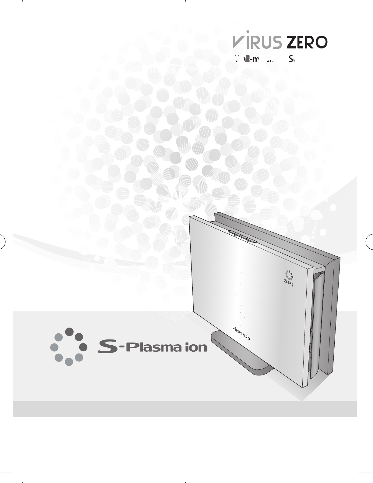
Wall-mounted/Stand type
Wall-mounted/Stand type
Wall-mounted/Stand type
Page 2
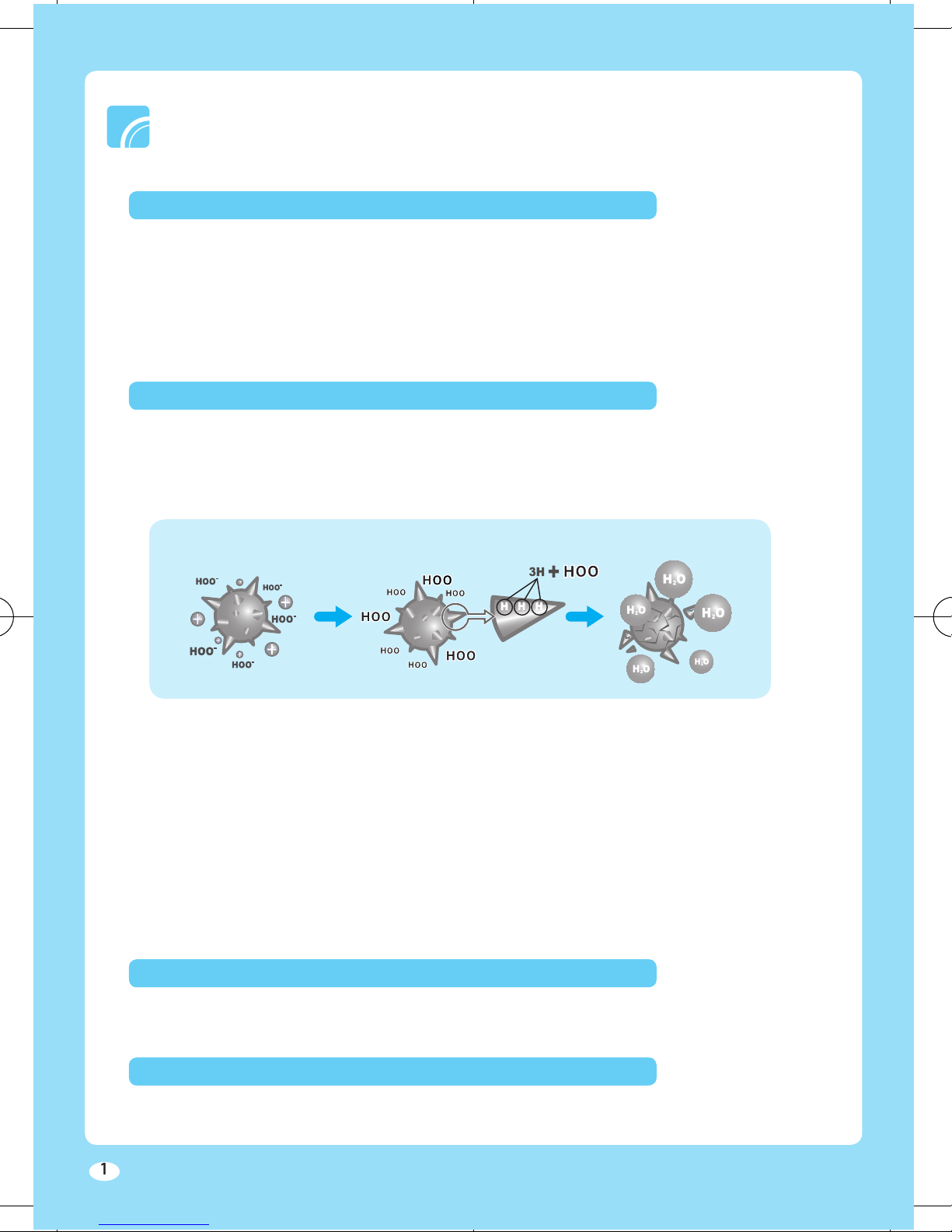
Mechanism of ion generation
with H+ and O₂ to form Hydrogen atom (H) and Oxygen ion (O₂-).
three hydrogen elements of its protein structure before forming water vapor. Also, the Hydrogen
Virus Elimination Mechanism
Anti Allergen
World Recognized Technology
Through the pin electrodes mounted on both sides of the product, SPi provides faster and more
Excellent air purifying technology
Enhanced performance
Stylish design
Page 3
........................................................................................................................................
3
....................................................................................................................
7
........................................................................................................................................
8
Before Using the Product
..................................................................................................................................
9
...............................................................................................................................
...........................................................................................
Troubleshooting
.............................................................................................................................................
..................................................................................................................................
Basic Operation
Other Information
Page 4
the power cable.
for an extended period of time, unplug
the power from the wall.
the power plug with wet hands.
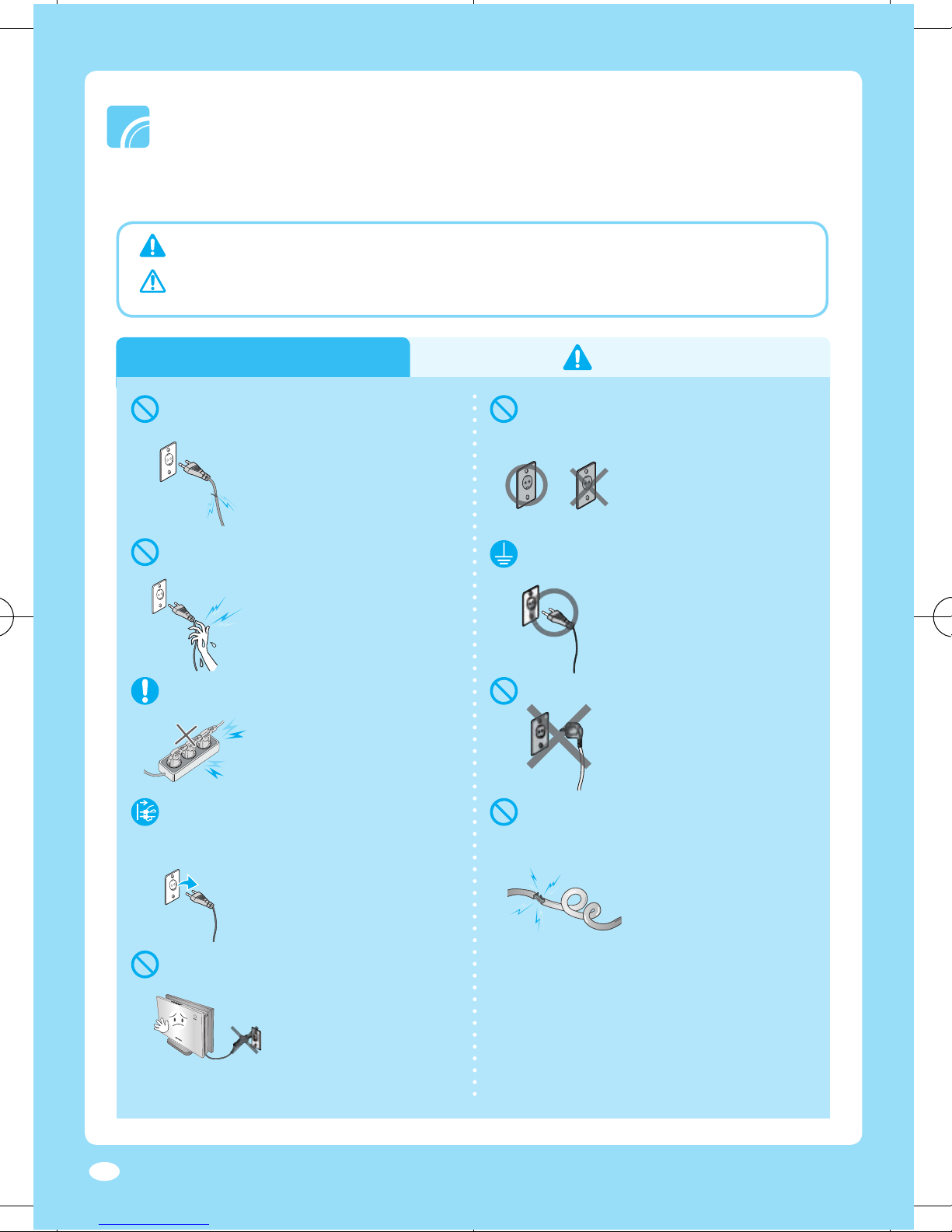
Hazards or unsafe practices that may result in severe personal injury or death.
Hazards or unsafe practices that may result in minor personal injury or
property damage.
Power supply
Potential risk of fire or
▶
electric shock.
Potential risk of fire or
▶
electric shock.
Potential risk of fire or
▶
electric shock.
220V 110V
Product may not
▶
operate normally and there
is potential risk of fire.
Potential risk of fire or
▶
electric shock.
Potential risk of fire or
▶
electric shock.
You can save energy and
▶
prevent electric leak or fire.
Potential risk of product
▶
damage or electric shock. Use
the power button to turn off the
power.
Potential risk of fire or
▶
electric shock.
Page 5
4
Follow the direction carefully.
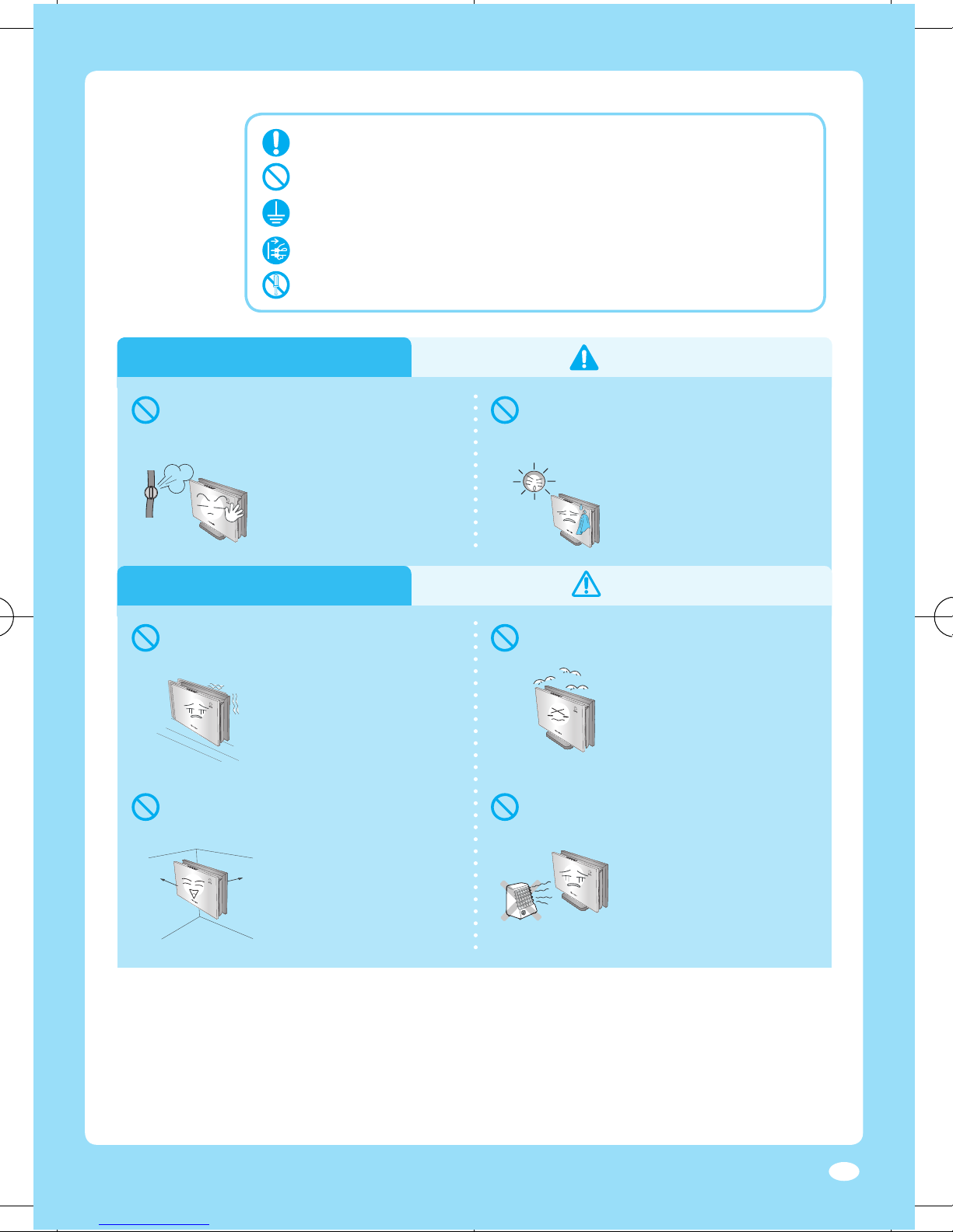
where fl ammable gas leaks or may
with oil fume or metallic dust.
Do not attempt.
Unplug the power plug from the wall socket.
Do not disassemble.
Make sure the machine is grounded to prevent electric shock.
Installing
Potential risk of explosion
▶
or fire.
Installing
If the product falls, it can
▶
be damaged or perform
abnormally.
There are potential risk of
▶
electric shock and
performance decrease.
Potential risk of fire or
▶
product damage.
If you cannot clear space
10cm
▶
around the product, it may
10cm
cause performance decrease.
Potential risk of fire.
▶
Page 6

Operating
the power plug immediately and
This may result in fire, injury
▶
or a problem with the
product.
Potential risk of fire or
▶
electric shock.
Potential risk of fire or
▶
electric shock.
Potential risk of product
▶
damage or electric shock.
Potential risk of product
▶
damage, electric shock or fire.
Contact service center when
repair is needed.
Operating
NO!
It may cause product damage
▶
or performance decrease.
If the product falls, they may
▶
get injured.
Page 7
Operating
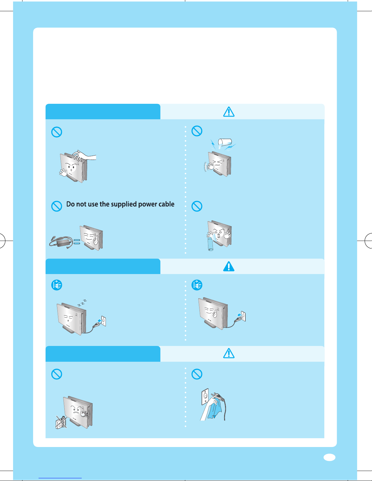
with any other products.
Potential risk of product
▶
damage or electric shock.
Potential risk of product
▶
damage or electric shock.
Potential risk or
▶
electric shock.
If the water gets into the
▶
product, stop the operation
and unplug the power
cable.
Potential risk of electric shock,
▶
fire or unit malfunction.
Cleaning
Potential risk of personal injury
▶
or electric shock.
Cleaning
Potential risk of fire or
▶
electric shock.
It may damage the surface
▶
of the product.
Potential risk of fire or
▶
electric shock.
Page 8
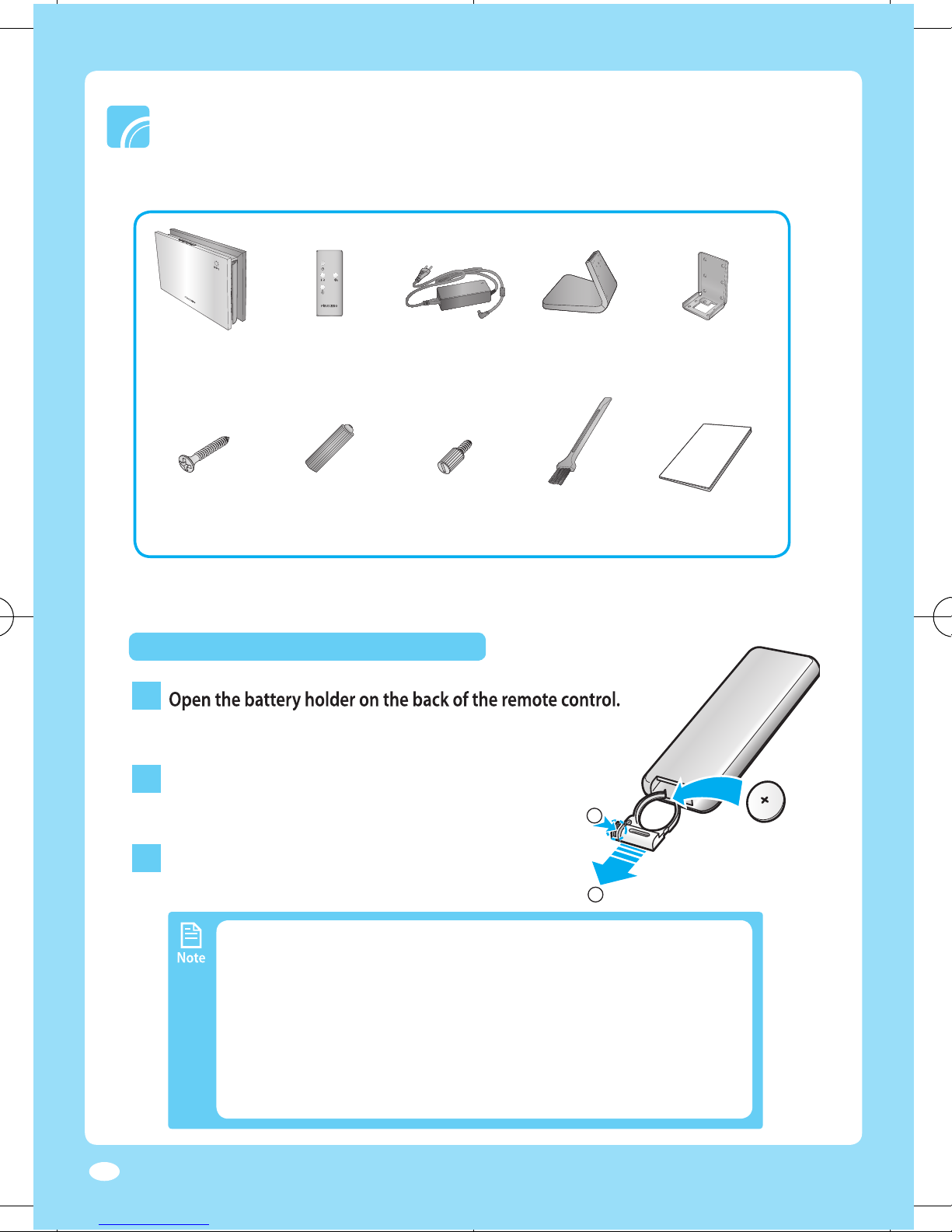
The fi gure in this manual may diff er from actual product.
Check if any contents are missing or damaged before using.
To purchase additional power adapter, contact our customer center (714-530-5791)
Wall Bracket
Installing a battery
Anchor
) and pull the battery holder out(
).
the battery.
Point the remote controller towards the remote control
The signal may not be received well of electronic lighting
If other electrical products operate by the remote controller,
1
▶
①
②
2
▶
1
3
▶
2
Page 9
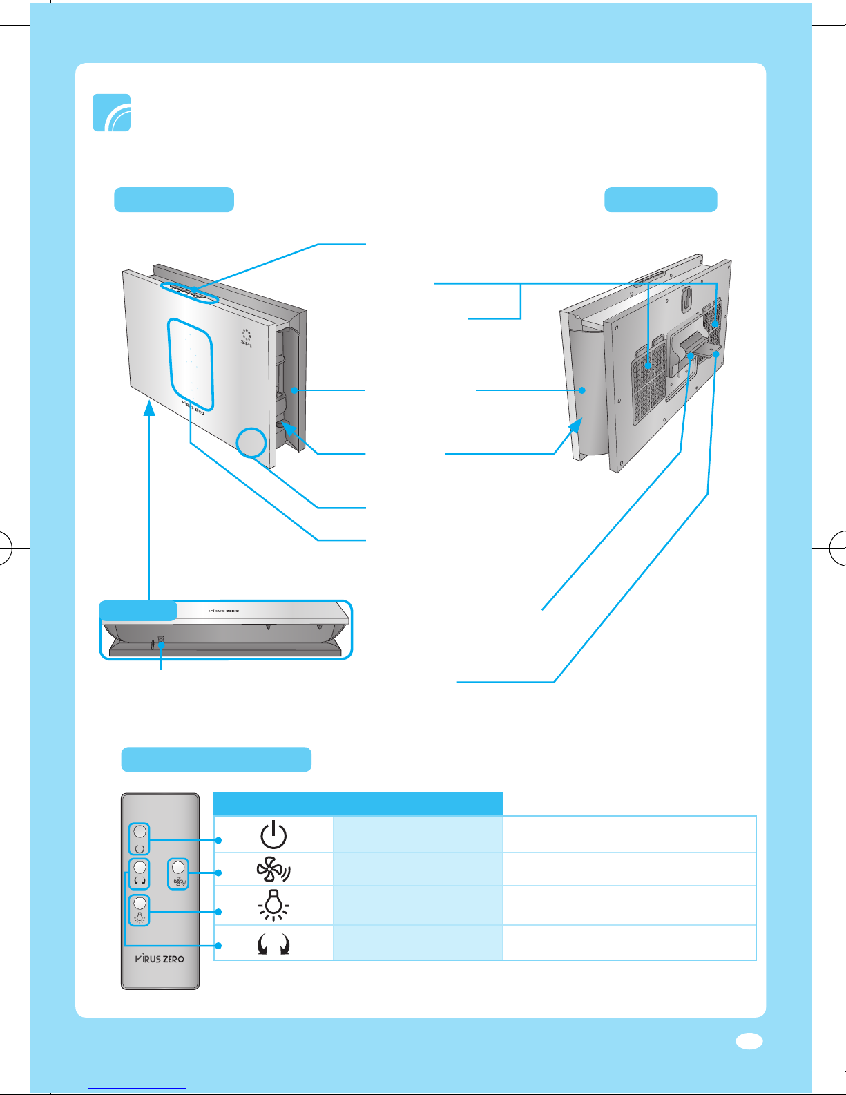
Front side Rear side
through here
Air flow blades
Adjusts the
Air inlet
Adjusts the height and the angle of the
Remote controller and control panel have same buttons and adjusts same functions.
Remote controller and control panel have same buttons and adjusts same functions.
Turns the power on/off
Turns LED indicator on/off
Wind Button
Adjusts the air fl ow direction
Bottom
Remote controller
Buttons on control panel and remote controller
Page 10
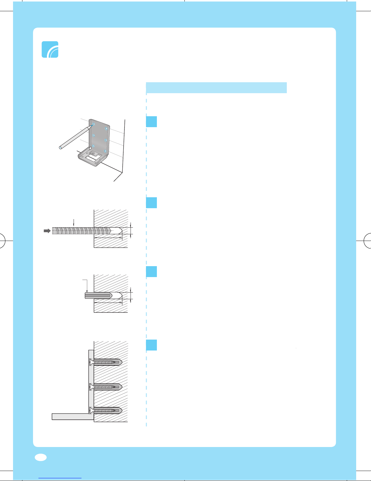
Installing a wall mount type
After locating the bracket to be attached on a
wall, adjust it horizontally with a spirit level and
wall with an electric hammer drill.
After inserting anchor into the drilled holes, strike
them with a hammer to insert deeply and then
the wall with a knife.
Wear protective equipment (gloves, safety glasses, etc.) for your safety.
Align the bracket holes on the wall where
are
are
1
Electric
Hammer Drill
Anchor
2
3
4
Page 11
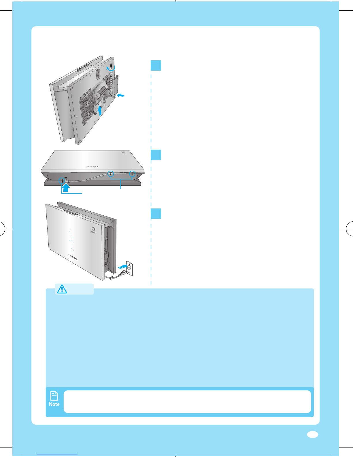
For the location on a wall to install the product, select a place where you can easily
After checking the internal structure of the wall, install the product on a solid place that
thin plywood), the product may fall.
When installing the product on a wall, keep and secure it horizontally to prevent it from
Always use a exclusive power adapter.
fire.
After inserting the bracket bar on the rear side of
the product into the bracket attached on the wall,
fi x the product with a clamping bolt.
When fi xing the product on the bracket, lift the
When connecting the power, the LED indicator of
the power adapter turns blue (operation standby)
Using the product in a place with low humidity (below 20%) may deteriorate the
Power Cable Holders
5
▶
6
7
▶
Page 12
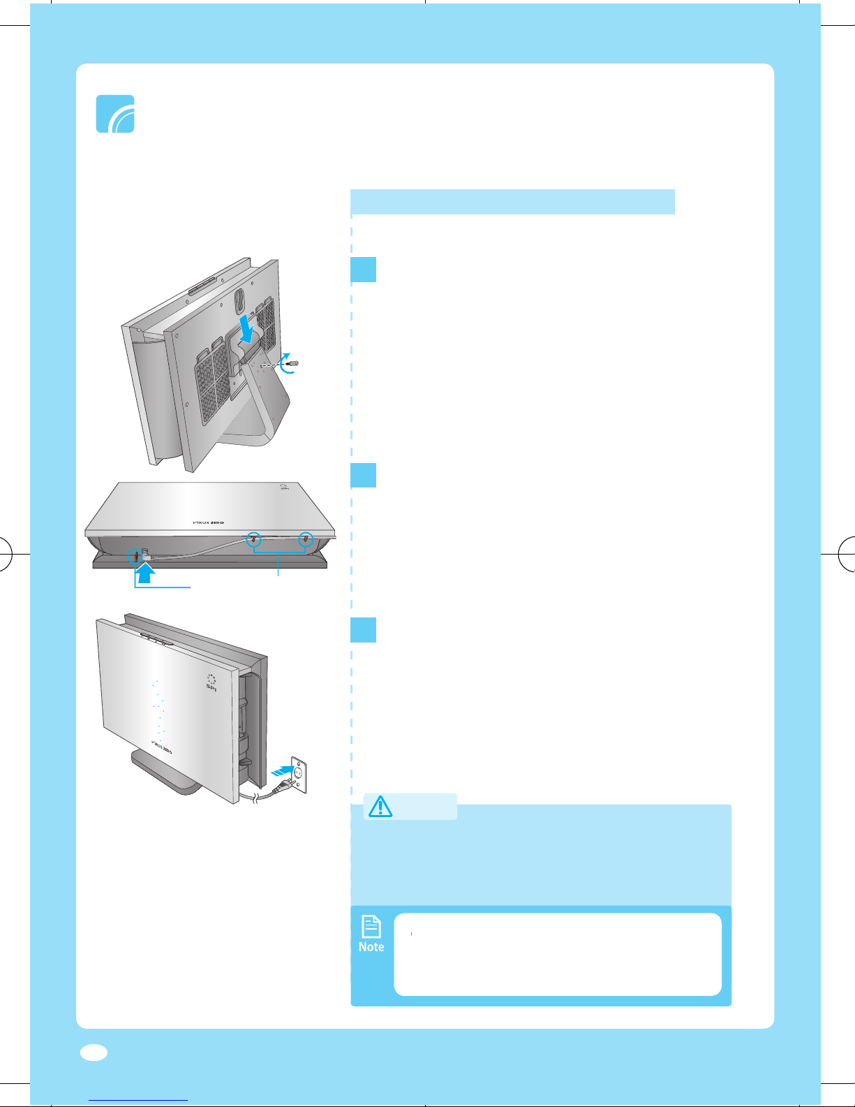
After inserting a bracket bar on the rear side of
the product into the supplied stand, fi x the
When mounting the product on the stand, you
When connecting the power, the LED
Always use a exclusive power adapter.
voltage may result in product malfunction or fire.
Using the product in a place with low humidity
the product.
Power Cable Holders
Installing a stand type
1
▶
2
3
▶
Page 13
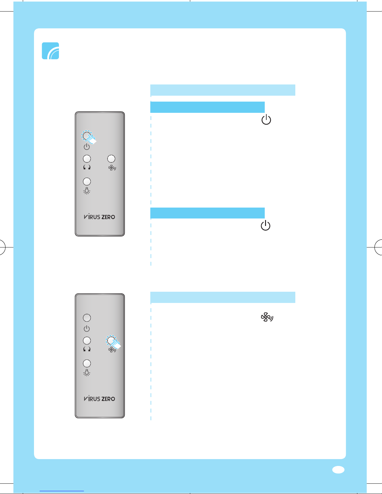
To start the operation, press [
] button on the
The LED indicator is turned on along with the
▶
The ion strength at the start of its operation is ‘low’.
Powering on/off
To stop the operation, press [
] button on the
The LED indicator is turned off along with the
To select ion strength, press [
] button on the
while operating.
Whenever the button is pressed, the operation mode
will be selected in order of (low)
Turning on the power
▶
▶
Turning off the power
▶
▶
Adjusting ion strength
▶
▶
Page 14
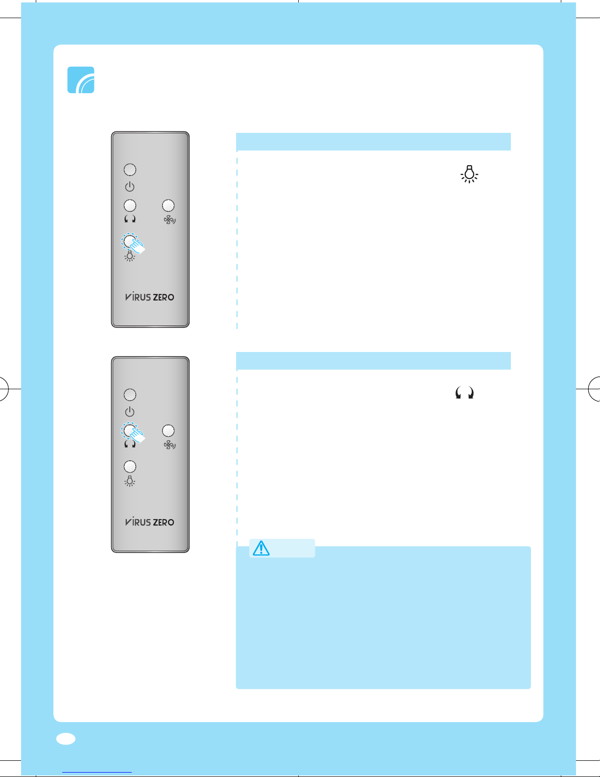
To adjust the air fl ow direction, press [
] button
To turn on/off the LED indicator, press [
] button
The stronger the ion strength is, the faster the blink
turned on regardless of the previous setting.
Turning on/off the LED indicator
Do not press any button by force or multiple buttons
Do not open or close the air flow blades in any way.
the overload of the fan motor by directing the wind to
the inside of the product.
▶
▶
▶
Adjusting air fl ow direction
▶
▶
Page 15
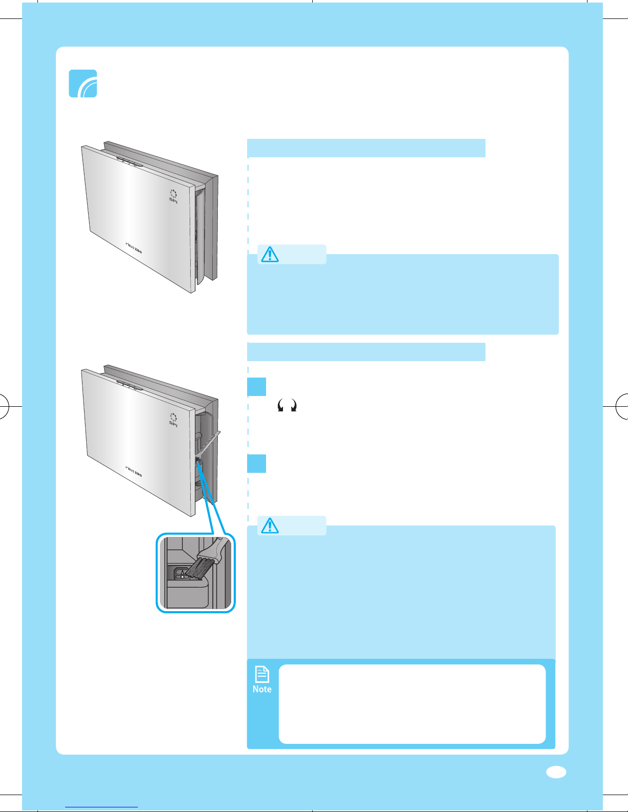
Turn off the power and unplug the adapter before cleaning the product.
To stop the operation of the air fl ow blades, press
] button on the remote controller or the
Wipe the surface of the product with a slightly
wet or dry cloth when needed.
foreign substances on the ion outlet.
Cleaning the exterior
when cleaning.
Clean the pin electrode every two weeks.
The cleaning term may differ on usage and
Accumulated dust on the pin electrode may
▶
Cleaning the pin electrode
1
2
Page 16
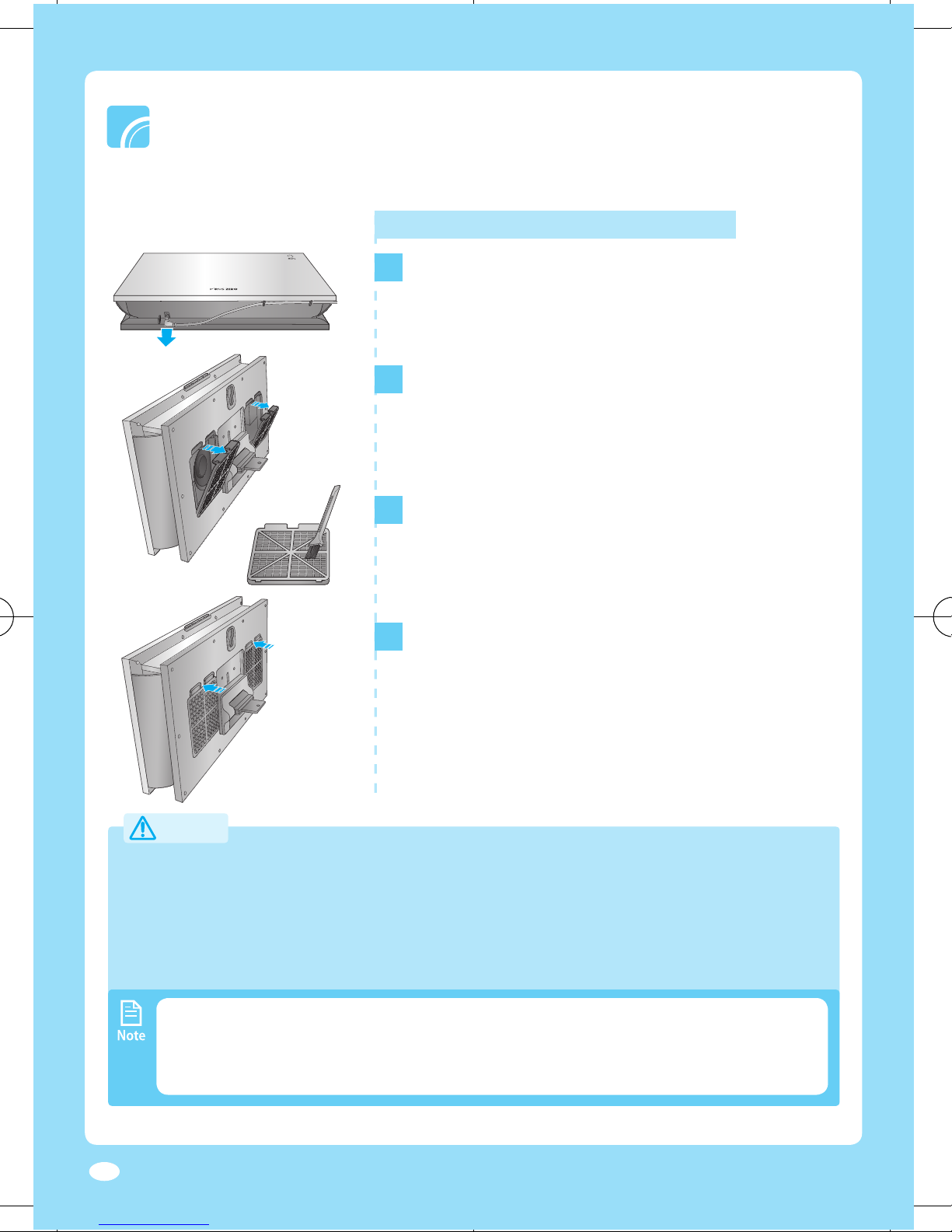
Cleaning the dust fi lter
As shown in the fi gure on the left, you can
with a cleaning brush.
After cleaning, assemble the fi lter again.
After aligning the lower part of the fi lter with the
When cleaning the dust filter of a wall mount-type product, disassemble the filter after
wall. It may result in personal injury or product damage.
Clean the dust filter every two weeks. The cleaning term may differ on usage
1
2
▶
3
4
▶
Page 17
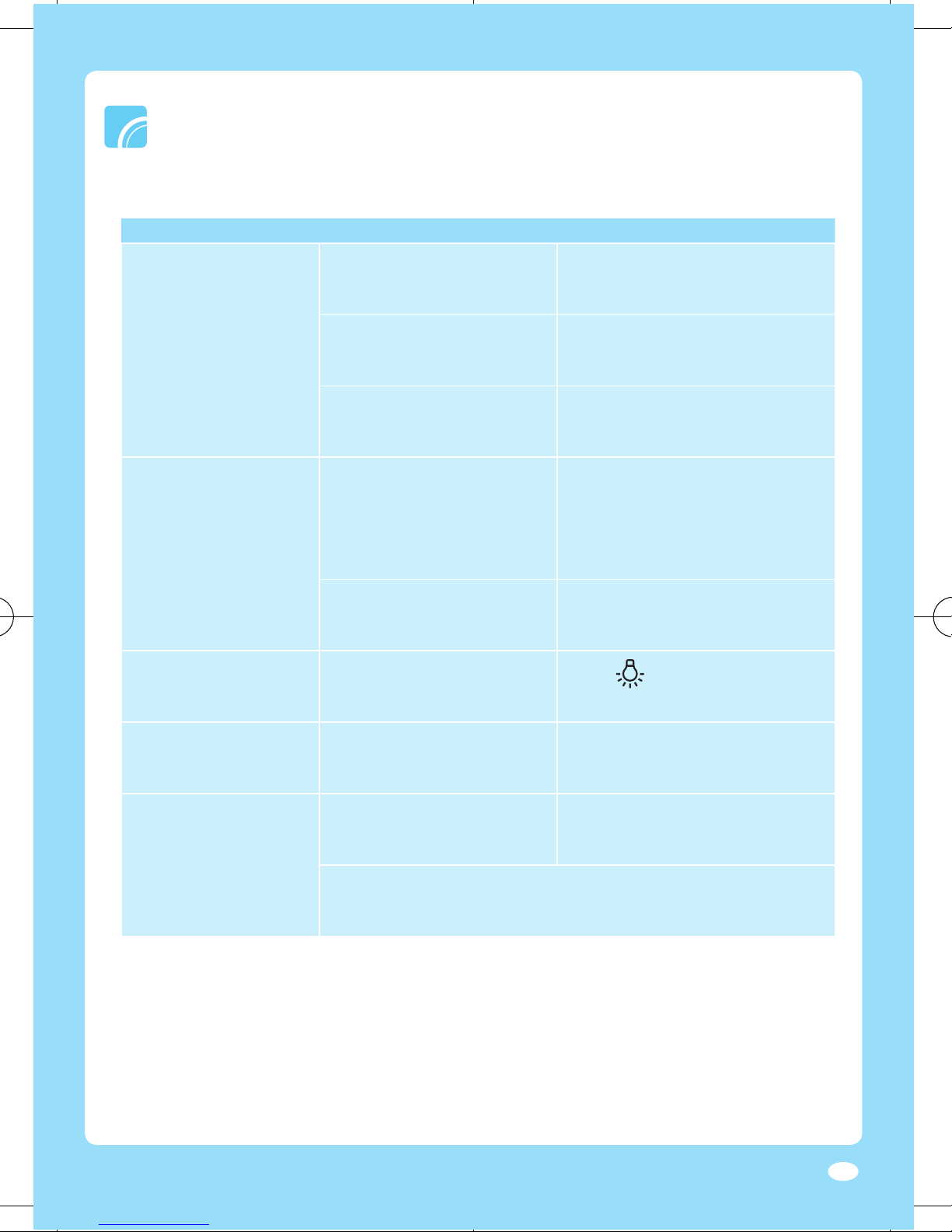
try again.
working properly.
Try another power receptacle.
] to turn on the LED
There is no air coming out.
with dust.
the product.
This product is equipped with a small fan. A small noise during opera-
tion is normal.
Page 18
419 X 80 X 246 mm
Page 19
Product Warranty
About warranty service
& Brook,Inc. will provide warranty service and the detail status of
the product will be notifi ed within 7days and the refund or pro
Product warranty is for
1 Year
Free warranty service Paid service
Type of defects or trouble Within warranty period After warranty expires
When the product shows performance or functional failure within the part service period.
itical performance and Exchange or refund N/A
Cr
functional failure within 10 days
from purchasing the product
Critical performance and Exchange or free repair N/A
functional failure within
a month from purchasing
the product
Defect occurred during Exchange N/A
shipping or installationn
Critical performance and Refund N/A
functional failure within a
month from product exchange
When product Refund N/A
exchange is impossible
When same failure Free repair Paid service
occurred twice
When same failure Exchange or refund Paid service
occurred three times
When different failures Exchange or refund Paid service
occurred five times
When the product is lost Exchange or refund Refund the price
during repair service deducted by the
depreciation amount
and added by its 10%
When the product repair is Exchange or refund Refund the price
impossible because parts deducted by the
are not in stock within the depreciation amount
part service period and added by its 10%
If the product defect is caused by user
When repair is impossible Refund after equivalent Refund the price
even though the parts are repair service fee is charged deducted by the
available depreciation amount
after equivalent repair
service fee is charged
When the product Paid service Paid service
repair is possible
Service fee will be charged if the product repair is requested when the
product is not defected.
When the product is not defected
Re-installation is required due to
false installation by installation
agency or repair doesn’t require
disassembling.
When the product requires
internal cleaning and
re-installation due to moving,
false installation or other reasons.
When the defect is caused by user
Defects caused by careless
handling or improper repairing
and modification.
Defects caused by using
improper power supply.
Defects caused by repairs done
at a place other than the Mag &
Brook, Inc
Defects or damages resulting
from dropping the product.
Defects caused by using
accessories not provided by
Mag & Broo k, Inc
Defects caused by not following
the ‘Safety information’ on the
user manual
Others
Defects resulting from natural
disasters such as fire, earthquake,
flood, etc.
Expiry of life time of consumable
parts (filters etc.)
Page 20
Distributor / Manufacturer : Mag & Brook, Inc.
Device provider : Samsung Electronics Co., Ltd.
Mag & Brook, Inc.
Customer Service Center
714-530-5791
Let us know the product model, problem and the contact
information. We will try to provide you with the fast and
satisfying solution.
 Loading...