

Page 1

User’s Guide
FS5i
Virtual Research Systems, Inc.
Page 2

December, 1995
The information contained in this publication is believed to be reliable, but Vir-
tual Research Systems, Inc. makes no warranties as to its accuracy or completeness.
Copyright 1995 Virtual Research Systems, Inc. All rights reserved.
Virtual Research Systems, Inc.
2326 Walsh Ave.
Santa Clara, CA 95051
phone: 408-748-8712
fax: 408-748-8714
e-mail:
info@virtualresearch.com
Page 3

FS5i
The
FS5i
is the integration of our top of the line FS5 HMD and our
FSCAN scan converter. The result is an HMD that accepts multiple signal
formats without the headache and expense of additional cabling. The
FS5i
maintains all of the functionality of the two separate devices, incorporating them
into a single, rack mountable enclosure. A new feature of the
FS5i
is a VGA
monitor output that replaces the field sequential monitor output of the
FS5.
This
allows the user to drive the HMD and a monitor without a VGA splitter or
additional cabling.(monitor out not available with field sequential input format.)
In addition, selectors for input formats and mono/stereo have been
relocated to the front panel.
The top cover of the enclosure need only be
opened to fine tune color
adjustments.(normally
not needed)
Initially, your
FS5i
will be shipped with separate manuals for the FS5 and
FSCAN. The functionality of the
FS5i
is the same as the separate units with the
above exceptions.
By following the guidelines in the separate manuals, one
should find the setup of the
FS5i
HMD to be simpler. A new, integrated
FS5i
manual will be shipped to you as soon as it is available. If you have any
questions or problems please contact Virtual Research for prompt assistance.
Page 4

Contents
ii
TABLE OF CONTENTS
INTRODUCTION TO THE FS5
SAFETY ISSUES
FS5 CONTROL BOX
Inputs
Video Input
outputs
MECHANICAL ADJUSTMENTS
Donning the
FS5
Interpupillary Distance (IPD)
Fore/Aft motion of shell
Display Height Adjustment
Overlap Adjustment
Ratchet Knobs
Headphones
Cable Positioning
OPTICS
POSITION SENSORS
Traeker Mounting
Reducing Tracker Jitter
PIN OUT INFORMATION
SYSTEM CONFIGURATION INFORMATION
23
Intergraph Platforms
23
1
2
14
14
15
15
16
16
17
17
17
18
19
19
21
22
Page 5

Contents iii
Division
ProVisionlO
System Configuration
SGI Reality Engine System Configuration
SGI Indigo2 Impact System Configuration
Other Systems and the F-Scan Converter
THE F-SCAN CONVERTER
26
TROUBLESHOOTING
27
24
24
25
25
Page 6

ChaDter
1 Introduction 1
Chapter 1
Introduction to the
FS5
FS5
is our new high performance head mount display (HMD) . At the heart of
the product are 1” cathode ray tubes (CRTs) capable of resolution and image
quality far superior to any available flat panel displays. The CRTs are black and
white tubes which run field sequentially; red, green and blue are created by
color shutters mounted in front of the CRTs. Although most users will drive
the
FS5
to VGA resolution, the CRTs are capable of up to 800 pixels horizon-
tally.
The
FS5
optical system excels as well. A custom design using
aspheric
sur-
faces on plastic elements allows us to achieve a
55”
field of view (FOV) while
maintaining sufficient eye relief for glasses wearers. By using plastic, we avoid
the weight problems of glass elements.
Mechanically, the FS5 retains many features developed and perfected in our
LCD product, the VR4. The rugged front shell protects the display components
and requires only two adjustments--interpupillary spacing and fore/aft positioning.The headband is a proven performer with thousands of hours of trouble free experience in the VR4. The high flex cable has an extruded jacket for
abrasion resistance.
Audio rises to a new level with the FS5. These Sennheiser closed cup head-
phones are the best compact headphone we have found.Whether your source
is simple monaural cues or top-of-the-line stereo, these headphones
will perform.
The FS5 control box has superior functionality as well.A set of front panel
LEDs
give instant status information. Brightness and contrast adjustments that
control both eyes together are also available on the front panel. Full right and
left RGB setup and gain adjustments are also easily accessed inside the control
box if fine tuning is desired.
Standard field sequential input is available from several image generators, in-
cluding SGI and Division. A similar field parallel format is available from
Intergraph platforms. Appropriate connectors are easily accessible at the control
box rear panel.
For other signal sources, an optional converter is available. The F-Scan Converter accepts either RS-170 RGB or
6OHz
VGA stereo signals and drives the
FS-5 directly.
The true test of any product is not the features list, but how it performs in your
application. We expect that the blend of features designed into FS5 will work
well for you. But if you have any questions or problems or special design requirements, please give us a call. We’ll do whatever we can resolve your questions and make your application successful.
Page 7

Chapter 2 Safety Issues 2
Chapter
2
Safety Issues
We take pride in building a safe product that will satisfy your requirements.
But the nature of our product--an electronic display device that you wear on
your head--creates the potential for problems. We strive to understand and
minimize the safety hazards associated with our head mount displays.
As an HMD user, you should understand those hazards too.
With that understanding, please make an informed decision about using this or any head mount
display product.
Blocked vision and hearing
By its nature, a head mount display blocks the user’s vision and hearing. The
danger of tripping over cables or other obstacles becomes a real concern while
immersed in the virtual world. As system manager, you must provide an environment that does not allow the. HMD user to fall or otherwise injure
him/herself. As a system user, you must survey your physical environment before entering the virtual environment to avoid problems. We recommend using
FS5
only while seated to avoid tripping hazards.
Eyestrain and other optical effects
FS5
will cause eyestrain if the interpupillary distance (IPD) is set incorrectly.
Like all head mounts, it is likely to cause some eyestrain effects even when correctly adjusted. This eyestrain stems from several causes, with perhaps the
most significant being the fixed focal plane which conflicts with the variable
depth cues present in the imagery. There is no technology we are aware of that
corrects this conflict.Other potential sources of eyestrain include optical aberrations, distortion, mismatch of computer imagery with mechanical configuration and display mismatch.
If you experience noticeable eyestrain, review and correct your mechanical ad-
justments and software configuration. If eyestrain persists, limit or end your
use of this device.
Lice/other pest transmission between users
Although we have not had any instances of user’s reporting lice transmission to
us, there has been at least one anecdotal report of lice transmission in a public
Page 8

Chapter 2 Safetv Issues 3
use HMD. There are sprays available that will kill lice on furniture and cloth-
ing. Two of these are RID and A-200. Both are available in drug stores. We
don’t have information on the effectiveness of these sprays on
HMDs
and encourage you to research this if you are considering a multiple user application.
These sprays are hazardous and you need to judge the benefits vs. risks of using them. Remember to read and follow the manufacturer’s directions.
Alcohol wipes are useful for cleaning the HMD between users. Alcohol will
remove skin oil and makeup that have transferred to the HMD. As far as we
know, alcohol has no effect on lice.
Electrical Shock Hazard
The desktop power supply produces
12V, -
12V and 5V DC.
All three voltages
are present in the control box. The HMD cable carries the 12V power to the
HMD. These voltages are too low to represent a significant hazard, even with
the control box open to make color adjustments.
The enclosure at the rear of the HMD contains high voltage circuitry required
for the CRTs. This enclosure should be opened only by trained, authorized
technicians.The voltage is sufficient to give a significant shock if contacted.
The voltage is also sufficient to arc across a few millimeter gap to any conductive surface--like a finger or tool. In our experience the shock from this voltage
is bothersome, but not dangerous because the current level is quite low. However, under worst case circumstances the effects would undoubtedly be more
severe (e.g. pacemaker users, etc.).
The top bar of the headband contains a cable bundle that carries these high voltages to the front of the HMD. Do not cut, drill, clamp or otherwise damage this
portion of the headband.
The front portion of the HMD consists of two display units within a shell.
The
wiring from the headband to the display units and the display units themselves
have the same voltage levels described above. There are no user accessible ad-
justments at the front of the HMD and no attempt should be made to insert fin-
gers, tools or other potentially damaging/conductive items into the front shell.
The shell should be removed only by trained, authorized technicians.
Extremely Low Frequency (ELF) and Very Low Frequency
(VLF) Emissions
Magnetic fields generated by electronic devices (Televisions, toasters, shavers,
household wiring, high voltage lines,
-etc,
etc, and
HMDs)
have been reported
to cause a number of severe health problems, including leukemia.
There is a
great deal of controversy at this time regarding the validity of these studies.
A
number of other studies have found no correlation between these emissions and
health risks.
Test equipment, a standard procedure and test limits for ELF and VLF
emis-
Page 9

Chapter 2 Safety Issues 4
sions for computer monitors have been developed in Sweden. While this test
seems relevant to head mount displays, the equipment is unsuitable for measuring the fields around miniature displays. There are no standard test procedures, equipment or standards for electronic devices other than computer
monitors.
Because there are so many unknowns surrounding this topic, we elected to
contract an expert in the field to develop test equipment and calibrate that
equipment for us. We have developed procedures for measuring the fields generated by our products using that equipment. After measuring the fields gener-
ated by our components, we add shielding and/or relocate components to mini-
mize the fields. This seems to be the prudent approach in view of the vast lack
of solid information in this area.
X-Ray Emissions
CRTs are capable of generating x-ray emissions under some circumstances.
Our CRTs operate at voltages below levels that produce x-ray emissions. The
CRT production process includes testing to verify this. The U.S. Food and
Drug Administration regulates CRT products to ensure adherence to x-ray emission standards. Our product information has been submitted to the FDA for review.
Further Information
If you have questions about any aspect of head mount display product safety,
please feel free to contact us directly. Our address, phone number and e-mail
address are listed at the front of this document.
Page 10
.
Chapter 3 Control Box 5
Chapter
3
FS5
Control Box
Box
Inputs
FS5
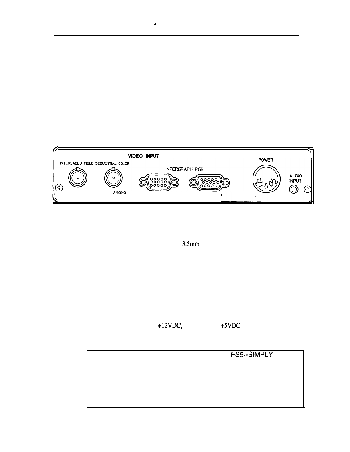
control box inputs are located on the rear panel:
fi
3
VlDEO
INPUT
RIGHT
LEFT
I PION
RIGHT
LEFT I MONO
Control Box Rear Panel
Audio
The audio jack is a standard stereo
3.5mm
mini phone jack. The control box
passes the audio signal through directly to the FS5 headphones; there is no amplification or audio adjustment in the control box. Audio signal level supplied
to the control box should be the same signal that would be supplied directly to
stereo headphones.
Power
The control box requires
+12VDC,
-12VDC and
+SVDC.
A universal power
supply comes with FS5. The power plug on the FS5 is a 5 pin DIN plug.
CAUTION: IT IS EASY TO DESTROY YOUR
FSS--SIMPLY
PLUG
IN THE WRONG POWER SUPPLY AND TURN IT ON.
TO AVOID THIS UNHAPPY EXPERIENCE, ALWAYS CHECK FOR
THE COLOR MATCHED BAND ON THE POWER SUPPLY PLUG
AND THE COLOR PATCH ON THE CONTROL PANEL. IF THE
POWER SUPPLY DOESN’T HAVE A MATCHING BAND, DON’T
PLUG IT IN!
Page 11
Chapter 3 Control Box 6
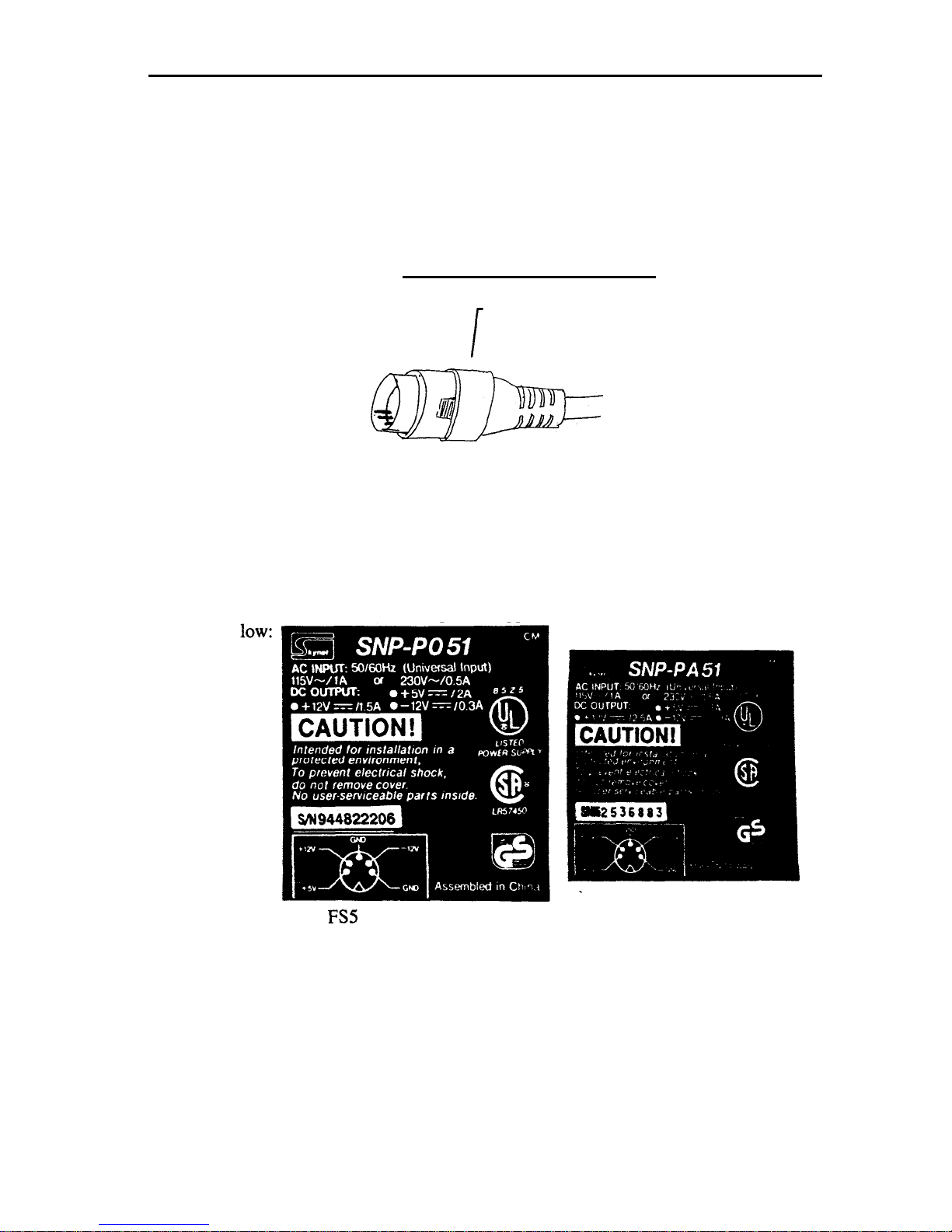
Because the 5 pin DIN plug is used on many power supplies, there is a real
hazard of plugging the wrong power supply into the
FS5
control box. To re-
duce the risk of this, we have added a
REID
colored band to the
FS5
power
supply and a YELLOW colored band to the F-Scan power supply. Always
check for correct color matching before plugging in a power supply to avoid
making an expensive mistake.
Power SupplyQuick Identification
colored band
RED BAND --
FS5
Power Supply
YELLOW BAND -- F-Scan Power Supply
No Band-- Don’t use!
As a further verification of power
supplies,
compare the label to the copies below
be-
FS5
Power Supply
F-Scan Power Supply
One particular example of this problem is the Polhemus Fastrak which also uses
a 5 pin DIN plug. The Fastrak power supply outputs a higher voltage and can
damage the unit
Page 12

ChaDter
3 Control Box 7
Video Input
~
FS5
accepts three video signal formats:
1) Field sequential
3xRS
170 RGB composite
2)
3xRS170
RGB parallel
3) F-scan format
Background Information on Video Formats
RS170
RS 170 refers to a timing standard developed for television that uses an interlaced format with 525 lines per frame, 262.5 lines per field. Frame rate is
30Hz
while field rate is
60Hz.
Line rate is 15,575 Hz (262.5 lines X 60 fields).
RS170
RGB
The term RS170 RGB refers to red, green and blue on separate wires, with
RS 170 timing. RS 170 RGB also requires vertical and horizontal (or composite)
sync. We speak of 5 wire RS170 RGB (red, green, blue, horizontal sync and
vertical sync); 4 wire RS170 RGB (red, green, blue and composite sync) and 3
wire RS 170 RGB (red, green with sync and blue).
For reference, our previous generation
product--VR4--accepts
3 and 4 wire
RS170 RGB.
FS5
Video Formats
Field
Seaquential
3xRSl70 RGB
Composite
This signal is based on RS170 RGB, but is quite different.
Rather than
transmit red, green and blue in parallel, the three colors are transmitted in sequence. To transmit all the information, the rate of transmission is increased by
3x. The information is transmitted on one wire. To distinguish the three colors, a longer vertical sync pulse is sent before red. The color order is red,
green, blue.
The timing for this format is as follows:
full frame rate: 30 Hz (same as standard RS170)
full field rate:60Hz (same as standard RS 170)
individual color field rate:
18OHz
(3x full field rate)
line rate:
47,250Hz
(262.5 lines x 180 fields)
Because RS 170 is an interlaced format, there is some added complexity in defining the order of sending field one and field two. From a timing standpoint,
the most straightforward order of transmission is as follows:
R field 1
G field 2
B field 1
Page 13

Chader
3 Control Box 8
R field 2
G field 1
B field 2
This order maintains the field
1,
field 2, field 1, field 2 cycle that is defined in
RS170 timing. It avoids the timing problems that arise in using the following:
R field 1
G field 1
B field 1
R field 2
G field 2
B field 2.
However,
FS5
can accept either order.
Video input connectors are BNC type. Connectors are labeled ‘RIGHT’ for
right eye input while using stereo mode, and ‘LEFT/MONO’ for left eye in stereo mode, or for both eyes in mono mode. These inputs are 750hm terminated.
3xRS170
RGB Parallel (Intergraph RGB):
3x RS170 RGB
parallel describes yet another related video format. This format
is a 5 wire video (R, G, B, H sync and V sync) which is run at 3x RS170.
So
the timing is:
Full frame rate: 90
Hz
(3x RS 170)
Full field rate: 180 Hz (3x RS 170)
Color field rate:
18OHz
(3x RS170)
line rate:
47,250Hz
(262.5 lines x 180 fields)
This format has been created because some computer manufacturers (Intergraph
in particular) can generate video at 3x RS 170, but do not have hardware configured to support putting all three colors on one wire. To accommodate systems
like
Intergraph
we have developed circuitry to accept 3xRS 170 RGB parallel.
This signal is input on HD15 pin connectors. The FS5 does the work of selecting R, G and B in sequence internally.
The
pinout
of this connector is given in Appendix 1. Video inputs are 750hm
terminated. Sync inputs are unterminated.
F-Scan Format:
FS5 also accepts a field sequential format that is generated by the F-Scan converter. This format is most similar to the field sequential
3xRS-
170 RGB composite format described above. It differs only in that H sync and V sync are
transmitted on separate wires. The signal is transmitted over a 15 pin to 15 pin
video cable from the F-Scan converter to the FS5.
Page 14

Chapter 3 Control Box 9
The F-Scan Converter accepts
60Hz
VGA or RS 170 RGB. It converts these
signals to the F-Scan Format. This allows use of the
FS5
with graphics
sources that cannot generate an FS5 signal format.
For further information about the F-Scan Converter, contact Virtual Research.
outputs
Control box outputs are located on the front panel of the box.
II
SC
=
=c-=
= _ z f
_=.
g
?
--
Virtual
Research
=
a
:
ABCD
VR MONITOR
BRlGHTNESS0CONTRAST
0
Control box front panel
Monitor Output
One channel of monitor output is provided at the front of the control box. The
output is from the left eye input. RGB outputs are line driven and 75ohm terminated. Sync outputs are unterminated
TTL
level signals.
The output signal format is not standard and will not work with most monitors.
The signal is generated by taking the field sequential input used by the FS5, and
splitting it out onto separate red, green, blue, H sync and V sync lines. This
signal has a field rate of 180
Hz,
and the colors are only present on each third
field.
There is a drawback to this approach--because the monitor is only receiving
color signals in every third field, the picture has about l/3 the brightness of a
normal picture. For many applications, this is not a significant problem. But if
your application requires high monitor brightness, this approach would not be
recommended.
We have not done any extensive monitor evaluation, but we have not found any
monitors that are specified at 180 Hz field rate. And in fact, several monitors
we have tested will not accept this field rate.
However, we have discovered that some monitors will operate at this rate. In
our lab we have worked extensively with the Hitachi SuperScan pro 21”. Although it is specified only to
160Hz,
this monitor operates at up to
2OOHz.
Page 15

Chapter 3 Control Box 10
HMD Output
The HMD output is a
26
pin AMP connector.
Pinout
from this connector is
given in chapter
7
of this manual.
CAUTION: do not plug or unplug the HMD connector while power is
ON at the control box. Always power down the control box before disconnecting the HMD.
Status Indicator Lights
There are eight LED status indicator lights located on the front panel of the
FSS
control box. These lights are marked with letters A to H. The meaning of each
light is given in the following diagram:
A
B
C
D
ON: left eye ON: Left eye
*’
ON: 15 pin inputs ON: no horizontal
/,
horizontal
vertical, problem-- selected
sync. present at
frequency out of
HMD disconnected
OFF: BNC inputs
video input(s)
range
or no video
selected
ON: right eye
ON: Right eye
ON: 15 pin F-SCAN ON: monoscopic
horizontal
vertical problem-- input selected
OFF: stereoscopic
frequency out of
HMD disconnected
OFF: 15 pin
range
or no video
Intergraph input
selected
E
F
G
H
Overall Brightness and Contrast Adjustments
The brightness and contrast adjustments located on the front of the control box
will adjust both eyes together. For best image resolution, set brightness so
blacks are just black (rather than gray) and keep contrast low.For a standard
video input, the brightness can be adjusted so high that the entire image will go
to white. Although this should not damage the CRTs, it is a good practice to
avoid overdriving the CRTs this way.
Control Box Internal Adjustments
Selectors for mono/stereo input,
F-SCAN/Intergraph
input and individual display setup pots are located inside the control box. To access these adjustments,
you need to open the control box. To do this:
1. Turn off power at the control box.
Page 16

Chapter 3 Control Box 11
2.
Disconnect cables from front of control box.
3. Remove two Phillips screws as shown below from front panel of control
box:
4.
Remove the front panel and bezel from the control box.
5.
Slide the top cover forward and clear of the control box.
6.
Reconnect the HMD connector to the control box output.
To reassemble, reverse the above procedure. Be careful to slide the cover into
the correct channels on the control box base.
Use normal caution in working
with the exposed board regarding ESD (electrostatic discharge). The components are not highly susceptible to ESD, but can be damaged if normal precautions are not followed.
Page 17

Chapter 3 Control Box 12
Internal Adjustments are located as shown below:
F-Scan/lntergraph Select -,
Left Vertical
J
Adjustments
Color adjustments
The FS5 SETUP and GAIN pots have been factory set to give a matched output on your HMD. We use an oscilloscope to check output voltage levels for
each color. If you feel the colors are off, it is best to start slowly with changes.
You may find the mismatch is worse rather than better after casual tweaking.
If you do adjust colors, start first with SETUP pots. These are used to set
black level at an even black (rather than greenish black or reddish black for instance). Next use GAIN pots to set white levels (rather than reddish white,
etc.).
All adjustments may be made with power ON to the control box and the
HMD
operating. If you experience any problems, it is best to power down the control
box, wait a few seconds, then power up again.
Page 18

Chapter 3 Control Box 13
Video Input Format Switches
Switch positions as viewed looking down at board are as shown below:
t
Select BNC input
t
Select F-Scan Input
SW4
n
SW3
rl
c
Select 15 Pin input
i
Select Intergraph Input
t
Stereo Input
0
SW2
Mono Input
1
power switch
front of control box
Refer to chapter 8 for system configuration information and to the video input
section of this chapter for details of the specific input formats.
In most cases, we will factory set your video mode switches to match the sys-
tem you are planning to use. You should be able to use your
FS5
without any
initial changes to the mode switches.
Page 19

Chapter 4
Mechanical Adjustments 14
chapter
4
Mechanical Adjustments
Locations of mechanical adjustments are shown in the following drawing:
Donning the FS5
There are several things to consider when first donning the
FSS.
1. The top ratchet should be adjusted to bring the sides of the headband down
to the base of the ear. See diagram:
Page 20

Chapter 4
Mechanical Adjustments 15
2.
3.
4.
5.
The rear ratchet should sit below the base of the skull, as shown in the dia-
gram above.
The cable should fall down the user’s back--not over the shoulder. The ca-
ble weight provides counterbalancing for the display weight.
It is easier to don the
FS5
with the earphones in anup position--out of the
way. After the other adjustments are made, it is easy to bring the earphones
down. While pulling them down, pull them out away from the head to
avoid bending your ear.
IPD, display height, and fore/aft motion adjustments are performed together
to optimize the view.
lnterpupillary Distance (IPD)
IPD range = 48-73 mm. This range is sufficient to cover from 1st percentile
teenager women to 99th percentile adult men. It should also cover a large percent of younger children, but we don’t have statistical information on younger
population groups.
Adjust until both images are evenly visible. Close one eye to
confirm
the image
is centered in front of the other eye. Incorrect positioning of the IPD adjustment
will lead to eyestrain.
Fore/Aft motion of shell
Pull shell away for easy donning. Push toward face to maximize field of view
and to block ambient light. Eyeglasses can be worn with FS5, simply leave
fore/aft adjustment near the outer position.
Fore/aft motion is controlled by a detent set screw that is accessible through a
hole at the center of the aluminum bracket at the top inside of the shell.
It re-
quires a
.050’*
hex head wrench to adjust. This tool is provided with the FS5.
The location of the set screw is shown in the diagram below:
Captive
Fore/Aft Tension
Page 21

Chapter 4 Mechanical Adjustments 16
.
The adjustment is slightly easier to make if the fore/aft adjustment is in the close
position. Insert the hex head wrench in the hole shown in the diagram. Move
the tool around and rotate it until it seats itself in the set screw.Adjustment is
somewhat counter intuitive: Turn clockwise to loosen, counterclockwise to
tighten the adjustment.If the adjustment gets too loose, the front assembly will
slide off the headband. Be careful to avoid this.
Adjust so that tension is sufficient to keep the shell from sliding by itself, but
not so tight that a user must push or pull with any significant effort to move the
shell.
CAUTION: DO NOT OVER -TIGHTEN DETENT SCREW.
IF DETENT IS OVER -TIGHTENED, USERS MUST APPLY
EXCESSIVE INWARD FORCE TO MOVE SHELL TOWARD THE
FACE AND EYES. WHILE THIS FORCE IS APPLIED, DETENT MAY
DISENGAGE, CAUSING THE USER TO PUSH THE OPTICS INTO
HIS/HER FACE AND EYES RESULTING IN INJURY.
Display Height Adjustment
The entire shell structure can be moved vertically relative to the user’s face. To
do this, grasp the metal headband and move it up or down relative to the leather
covered forehead band. When display height is correctly adjusted, the top and
bottom of the CRT
.will
be equally visible.
Overlap Adjustment
This adjustment requires factory disassembly. Specify position when you or-
der, or return to Virtual Research for retrofitting.
Partial overlap setting requires stereo video inputs, but allows a wider field of
view than 100% overlap.
[As of this writing, the partial overlap position development work is incomplete.Some shell redesign work is needed to allow the outward tilt of the displays. Please contact Virtual Research for up to date information]
Page 22

Chapter 4 Mechanical Adjustments 17
Ratchet Knobs
Tension of ratchet knobs is adjustable by turning the Phillips screw at the center
of the knob.
Headphones
Headphones rotate around the knobs on the sides of the headband. When don-
ning the
FS5
unit, rotate the headphones above the headband. After video is
adjusted, pull the headphones down. This makes fitting faster and easier.
Rotation tension is controlled by tightening the knobs. Over tightening can
cause failure of the knob or the plastic bolt.
Cable Positioning
FS5 is designed to be lightweight and well balanced. The cable bundle provides a significant counterbalancing effect without adding weight to the product.
The cable bundle should drop directly down the user’s back. If the cable is
draped over the user’s shoulder,
FS5
will be front heavy.
The position sensor
cable should follow the cable bundle to add additional counterbalance weight
and to minimize the tangle of separate cables.
Page 23

Chapter 5 Optics 18
.Chapter
5
Optics
Avoid scratching the FS5 Optics.
FS5
optics are plastic and are prone to scratching. Eyeglass lenses and eyeglass
frames are especially likely to cause damage to your
FS5
optics.
FS5
is de-
signed with rubber bumpers around the lenses to minimize this contact. But the
bumpers won’t stop all contact, so be cautious when you wear glasses with
your FS5.
If this isn’t enough incentive, as your glasses damage the FS5 optics, the FS5
optics may damage you glasses. Be careful.
If worst comes to worst, FS5 lenses are factory replaceable. Contact Virtual
Research for details.
Eyeglasses:
Leave On or Remove?
In general, it is better to wear the FS5 without glasses. Without glasses, you
can bring the optics closer to your eye, but with glasses, you need to leave the
optics farther away. The optical exit pupil (the place in space where your eye
needs to be to see the screen clearly) is cone shaped and narrows farther from
the FS5 optics. As your eye moves farther from the lens, you need to be more
careful in adjusting the fit of the HMD to achieve good imagery.
The FS5 optical system is designed to place the image plane at about 5 ft
(1.5m).
If you wear glasses, but are able to see objects at 5 ft clearly, you will
find it is better to wear the FS5 without your glasses.If your vision is blurred
at 5 ft, you will probably find it is better to wear your glasses, even though you
are farther from the lens. If in doubt, try it both ways, then decide.
Bifocals can be a problem for HMD wearers. Near objects and far objects are
really all at the same distance, so bifocals tend to just get in the way.
While we can’t seriously recommend it, one customer has used HMD usage as
a work related reason that he required radial keratotomy and convinced his insurer to pay for the procedure that is normally not covered.
Lens Fogging
FS5 is supplied with a no-fog cloth to reduce fogging of lenses. To use it,
breath on the lens to create a fog, then gently wipe off with no-fog cloth.Keep
no-fog cloth in closed pouch so it doesn’t dry out. Reapply if fog reappears.
The no-fog cloth leaves a residue on the lens.A thin coating doesn’t have an
appreciable effect on image quality through the lens. But excessive application
will cause some degradation of image quality.
Page 24

Chapter 6 Position Sensors 19
chapter
Position
6
Sensors
Tracker Mounting
FS5
is designed to be used with a variety of position sensing options. The position sensor mounting bracket behind the top ratchet has mounting screws located for a Polhemus or Ascension receiver. The outer holes are sized for the
Ascension, while the inner holes fit the Polhemus.
Position Sensor Mounting Bracket
K
outer holes for ascension mount
c(.
inner holes for Polhemus mount
The mounting bracket holes are positioned so the tracker is turned 90” from the
HMD axis. Using this receiver position requires a software rotation of the receiver position.
Page 25

Chapter 6 Position Sensors 20
Tracker Rotation (Axes are those used by WorldToolKit)
UP
t-y)
t
line of sight (+Z)
90” rotation needed
some rotation about X maybe needed
left side (-X)
The correct position will have a 90” rotation about the Y axis. You should set
rotation about X after testing the system with no rotation.
Exact rotation about
X may depend on the user, although we have not worked enough with this to
be certain.
If your software has difficulty with this rotation, we can send you a mounting
plate with holes at 90” rotation from those shown above. For a quick fix, cus-
tomers have used velcro with adhesive backing.
The Logitech Ultrasonic tracker requires a triangular mounting hole pattern. We
can supply (at no charge) an adapter plate for the Logitech receiver.
Other trackers are becoming widely available.
If you would like to mount an-
other tracker on your
FS5,
let us know. We can probably supply basic hard-
ware for mounting. We are always glad to have feedback on your experience
with new trackers.
Position sensor cabling is most easily handled if you attach it to the
FS5
cable
bundle. This can be done with electrical tape wrapped at about 18” intervals
around both cables. However, this does leave some sticky residue when you
remove the tape. You can lay the smooth tapesurface against the cables and
finish by doubling the tape back on itself to avoid this residue. We don’t recommend plastic cable ties since they tend to snag on everything.
Page 26

Chapter 6 Position Sensors 21
Reducing Tracker Jitter
Electromagnetic trackers are prone to jitter. This effect can be subtle, or horrendous, depending on the conditions in which the tracker is used. A good
place to start is with a diagnostic setup.
Place the receiver and transmitter near
each other and well away from other possible sources of interference. We find
it is easiest to diagnose if we view a virtual scene on a large monitor and watch
for image jitter in that scene. Don’t use the HMD display for this; it’s hard to
move equipment while looking into an HMD and impossible to test for HMD
interactions. While watching the monitor, move the transmitter and receiver
apart and watch the jitter increase.
ambient jitter.
You should now-have a fair sense of your
Now bring suspect pieces of electronics or metal into the area of the receiver.
Turn the electronics on and off. Move the transmitter/receiver farther apart and
the electronics closer to the receiver, then try again. Notice how objects cause
warpage
of the electromagnetic field--causing the sensor output position to
change, as well as jitter.
Bring the
FS5
near the receiver. Notice that the jitter becomes severe when the
receiver is near the CRTs or the circuitry at the rear end of the HMD.
At the
tracker mount, the sensor should be nearly unaffected by the HMD.
Try the following jitter reduction steps if you are having problems:,
1.
2.
3.
4.
Keep the source and receiver as close together as possible. More than
anything else you do, the distance from source to receiver will effect you
performance.
Turn off or move away equipment that causes interference.
Monitors and
computers (especially computers that are partially open) produce fields that
will add jitter to your tracker.
Mount the transmitter above the receiver. This will maintain a clearer line
of sight from transmitter to receiver and reduce field
warpage
due to metal
parts of the FS5.
If the I-IMD seems to be a significant source of jitter or field
warpage,
mount the receiver on a plastic arm that moves it farther from the electronics
of the HMD. Use the diagnostic setup described above to figure out the po-
sition that works best for your situation.
Page 27

Chapter 7
Pin Out Information 22
Chapter 7
Pin Out Information
Interprauh Innut
and Monitor
Outuut
connector format
15 pin high density D female connector
Pin
1
2
3
4
5
6
7
8
9
10
11
12
13
14
15
Signal
RedVideo
Green Video
Blue Video
Ilk
ground
ground
ground
ground
reserved for auto enable of intergraph mode--do not connect
ground
n/c
Ilk
horizontal
sync
verticalsync
reserved for auto enable of F-Scan mode--do not connect
Page 28

Chapter 8
System Configurations 23
Chapter
8
System Configuration Information
The following information is intended to help describe system configurations
that have been successfully used by Virtual Research, or by other
FS5
custom-
ers. If you find an alternative configuration works better or have problems with
a configuration described here, please let us know.
Intergraph Platforms
Virtual Research is currently using the following system configuration for
FS5
testing:
TDZ30 with two
GL2
graphics card sets
I-l
electromagnetic transmitter
0
Tracker
Box -
HDl Smak
to
HDl Smak
receiver for glove or wand
-
optional VGA distribution amp.
VGA loop through
cable supplkd
by Intergraph
I
I
use monitor out as alternative to VGA dist. amp.
HDl Smak
to
HDl Smale
Hitachi
SuperScan
Pro
21”
monitor
Our current system configuration uses a Polhemus Fastrak tracker and Sense8
WorldToolKit
software.
-
Page 29

Chapter 8 System Configurations 24
A special Intergraph driver is required to configure the GLZ boards to provide
180Hz
RS170 video output. As of this writing, that driver has not been for-
mally released. We are using a test version of the driver on our system.
It is not necessary to use two GLZ board in the system shown above.
If you
use one GLZ board, plug the GLZ output into the LEFT/MONO input of the
FS5
and move the MONO/STEREO switch to MONO.
Division Provision1 0 System Configuration
In preliminary tests with Division, we had no problem running the
FS5
directly
from the
PVlO
in mono and stereo modes.
As of this writing, Division is awaiting delivery of an FS5 for verification test-
ing with the FS5 prior to a formal release of the software driver.
Contact Division directly for further details of system configuration.
SGI Reality Engine System Configuration
We have tested the following system configuration to some extent:
electromagnetic transmitter
13W3
male to @NC
hakout csbk
Hitachi
SuperScan Pm
21” monitor
To deliver the correct video format to FS5, a new video output format (VOF) is
required.A tape with the VOF will be shipped with your FS5 if you are using
an Onyx. The format is titled
64Ox480_18Oiq.u.
L
Page 30

Chapter 8
System Configurations 25
The problem you are most likely to face is portrayal of imagery in black and
white on the HMD that should be in color. This problem results from a limitation of the SGI software to generate field sequential color. SGI engineers assure
us that the problem should not occur in windows that are generating graphic im-
ages, but we don’t have any real confirmation of this yet.
The Onyx multi-channel option (MCO) for the RE2 cannot drive the FS5. Al-
though it is theoretically possible, SGI efforts are focused on the RE3, which
will provide a more flexible support for products like the
FS5.
Unfortunately,
MC0 software for the RE2 is a lower priority. To run stereo from an
RE2
with
MCO, output VGA and use an F-Scan converter.
SGI Indigo2 Impact System Configuration
The Indigo2 Impact is not capable of driving the
FS5
directly. However, the
Impact Channel Option (ICO) which is still in development as of this writing,
will drive the
FS5
directly. It will be capable of stereo as well as mono.
We don’t yet have details of the exact system configuration.
Contact SGI for
further details on availability of the ICO.
Other Platforms and the F-Scan Converter
PC, Apple Macintosh, Sun, Evans and Sutherland, and SGI platforms not
named above are not currently able to output a video format directly
useable
by
the FS5. To allow a broad range of platforms to drive the FS5, we have devel-
oped the F-Scan Converter. See chapter 9 for further details on the F-Scan
Converter.
Page 31

Chapter 9 F-Scan Converter 26
Chapter 9
The F-Scan Converter
The F-Scan Converter will allow you to drive the
FS5
with a VGA or RS 170
RGB source. Input to the F-Scan Converter is one or two channels of video.
Video may be
3,4
or 5 wire.
Output from the F-Scan Converter is one or two
channels of field sequential video in
3xRS
170 RGB format.
VGA format video must be
6OHz,
640x480. Higher frame rates will not work.
RS 170 RGB is the same format accepted by the VR4. With an F-Scan Converter, you should be able to substitute an
FS5
directly for a VR4 in your appli-
cation.
Contact Virtual Research for further information on the F-Scan Converter.
Page 32

Chapter 10
Troubleshooting 27
Chapter 10
Troubleshooting
PROBLEM
yeen
power light not on at
control
box when switch is
In
power light blinks on and
off
HO VIDEO
no video at
HMD
Horizontal status light error
CHECK FOR
correct
power supply--check
color
coded ring on plug
power supply not plugged
into a live circuit
this is probably a serious
problem requiring factory
service. Try powering
down and back up. If the
problem persists or returns,
contact virtual research
check status lights--see descriptions of lights on manual page 10.
check that video source is
plugged into correct channel
of control box.
check input switch settings
inside control box for correct
configuration see page 13 of
manual
This is probably due to incorrect video format sent to
the
FS5.
Recheck your
video format. Check with
Hitachi monitor if available.
Monitor will show
47kHz,
180Hz if video timing is cor-
rect
COMMENTS
fuses
in
FS5
control box are
self resetting, so the problem
is not due to a blown fuse
If there is a short somewhere
in the circuit, the resettable
fuse may blow and reset repeatedly
Another quick test: Send the
signal to a regular monitor.
lf
you see a good image,
you are not sending
FS5
format, which will not work
on most monitors.
Page 33

Chapter 10 Troubleshooting 28
vertical
status light error
no video at HMD, status
ights show no problem with
ride0
left eye working, but right
eye
dark
ntergraph left eye working,
but
right eye dark
VIDEO
PRESENT BUT
NOT
CORRECT
Image appears all blotchy
with
colors changing
Video images present, but
hazy
overall
Displays are completely
bright white
intergraph image appears in
black and white
Shutter appears stuck on one
or two colors
commonly
due to HMD
un-
plugged
from control box.
Use
likely result of incorrect
video
feed to HMD. If
IMD
is plugged in, recheck
video
format.
adjust control box front
panel brightness and contrast
pots
rideo source may be sending
Ilack
image--check with
os-
:illoscope
or
180Hz
monitor
nay be in stereo mode when
:xpected
to be in mono
node
Intergraph graphics must be
:onfigured
for stereo and
dual display
This
is normal shutter
benavior when it is first turned
on.
The problem should
disappear within 30 seconds
CRT may be blooming.
Turn
down brightness and
contrast. The image quality
should improve
turn down brightness and
contrast at control box front
panel.
If this doesn’t help, you may
be sending an incorrect
video signal
control box is configured for
F-Scan input rather than
intergraph input. Check status
lights. Change SW 3 position
Power down HMD, wait a
few seconds, then power
UP*
horizontal
and vertical timing
If
video signal are correct
and
sync signals are present.
Maximum image quality will
always be achieved at the
lowest contrast level that is
acceptable.
Shutter can latch if power
down cycle is too short
Page 34

Chapter 10 Troubleshooting 29
on
SGI Onyx, portions or all
If
the scene are black and
vhite on the HMD
MECHANICAL IMAGE
PROBLEMS AND
IMAGE
MISMATCH
video
image is blurry at one
edge
or comer
corners
of image are lost
Colors
appear smeared or
ainbow
like at edges of
dis-
Ilay
One
eye is brighter than the
Ither,
or colors are different
in the two eyes
image in the two eyes are
different widths or are rotated relative to each other
images are different heights
this is a software limitation
of the SGI. Contact Virtual
Research for further details.
your eye is off to one side
from the exit pupil of the
optics. Try adjusting the
lPD
or vertical position of
the displays again.
your eye is too far from the
lens. Pull the shell closer to
your face.
this is a normal limitation of
the lens design. Different
light colors are bent differ-
ently by the lens. The effect, chromatic aberration, is
more severe the farther from
the center of the display
switch video signals if you
are running in stereo to see if
the problem is caused at the
control box, or at the computer
if the problem is control box
related, adjust SETUP and
GAIN pots inside control
box.
This is an image alignment
problem that requires factory
service. Please contact virtual research.
this can be adjusted at the
control box, but please contact virtual research before
making any adjustment
T-
This
is more of a problem
or those who wear
eye-
glasses.
If you are reading text, keep
it toward the center of the
display.
nake sure you have the
dis-
Ilays
aligned to your eyes
tnd
as close to your eyes as
)ossible
to limit all
aberra-
ions.
.mage
mismatch problems
will
cause eyestrain and
should
be fixed promptly
image mismatch problems
will cause eyestrain and
should be fixed promptly
Page 35

Chapter 10 Troubleshooting 30
stereo input, images aren’t
make sure everything is OK
image mismatch problems
fusing into one stereo image
with the HMD by testing in will cause eyestrain and
MONO mode. If this is OK
should be fixed promptly
and the problem persists, it
is due to software configuration. Adjust convergence/parallax as appropriate
MECHANICAL
PROBLEMS
front shell fore/aft motion
too loose or too tight
adjust detent screw at front
of headband--see manual for
instructions
HMD
seems front heavy
HMD cable and tracker cable
should fall down user’s
back, not over shoulder.
With cable at back, weight
should be centered
headband ratchet knobs too
adjust ratchet tightness with
loose or too tight
phillips
head screw at center
of ratchet knob
 Loading...