

Page 1
RUDDO, STEP ON FOR REAL
USER GUIDE (ENG)
Rev. 2.0
March 2017
Page 2

RUDDO | User guide
Page 3

INDEX
1. PACKAGE CONTENTS
2. ASSEMBLY
3. CONFIGURING BRAKES AND RUDDER HARDNESS
4. RUDDO CALIBRATION ON WINDOWS
5. RUDDO CONFIGURATION ON MICROSOFT
FLIGHT SIMULATOR (MFS) AND PREPAR3D
5.1. Through the MFS-Prepar3D menu
5.2. Through the “VF-Test&Calibrate” control panel
6. CONFIGURATION ON X-PLANE 10
4
6
8
13
14
14
15
17
Page 4

RUDDO | User guide
1. PACKAGE CONTENTS
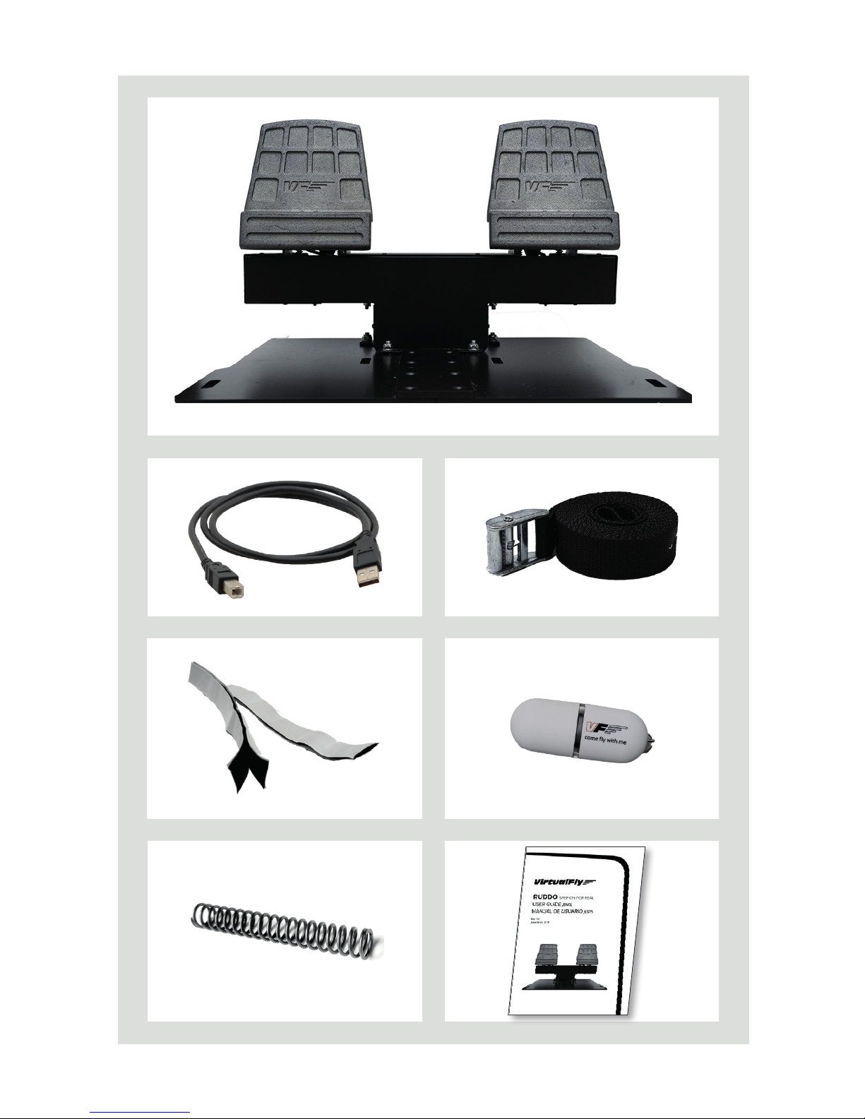
1. RUDDO (1 unit)
2. USB data Cable (1 unit)
3. Subjection strap (1 unit)
4. Adhesive backed Velcro strips (2 units)
5. Memory stick (1 unit)
6. Spring (2 units)
7. User’s manual (1 unit)
Page 5
54 –
1
5
3
4
7 6
2
Page 6

RUDDO | User guide
2. ASSEMBLY
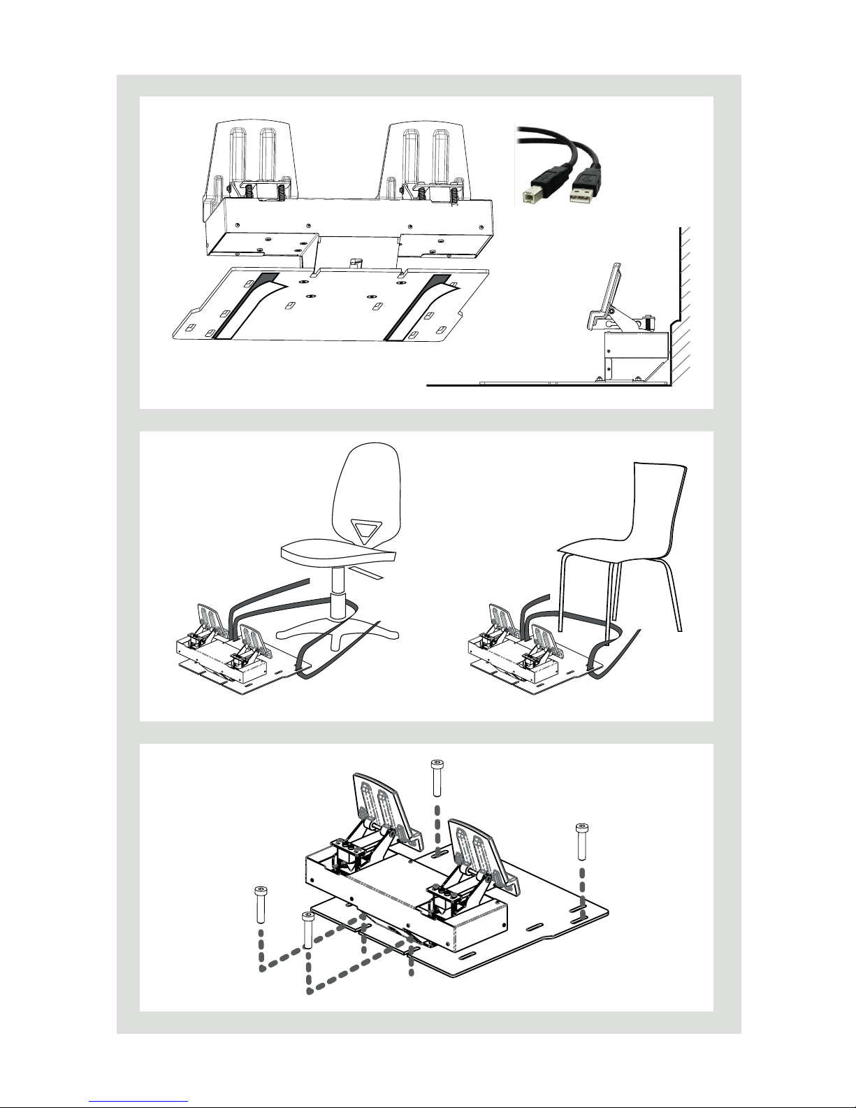
Placement (Figure A)
• Place the RUDDO on the oor in front of the chair in the desired position. If it’s possible we recommend to place in contact with the wall.
• Use the adhesive backed Velcro strips (4) to x the RUDDO on the
oor.
• Connect the USB data cable (2) between the rear connector of
RUDDO and the computer.
Subjection strap (Figure B)
We provide you a subjection strap (3) to minimize the chair move-
ments while the brakes are applied:
• Lift the RUDDO from the oor and thread the strap through the
RUDDO’s base holes.
• Pass the strap through the chair securing the subjection.
• Pass the end of the strap through the tensioning tool and pull tight
until the chair is at the desired distance.
Fixing to the floor (optional) (Figure C)
The RUDDO can be xed on the oor thanks to the holes placed
on its base. You will need 4 screws (not included) to assure that the
device is rmly xed to the oor.
Page 7
76 –
Figure A
Figure B
Figure C
Page 8
RUDDO | User guide
3. CONFIGURING
BRAKES AND RUDDER
HARDNESS
We oer the possibility to adapt the rudder and brake hardness to your
preferences. There are two modes available harder and softer.
Brake hardness
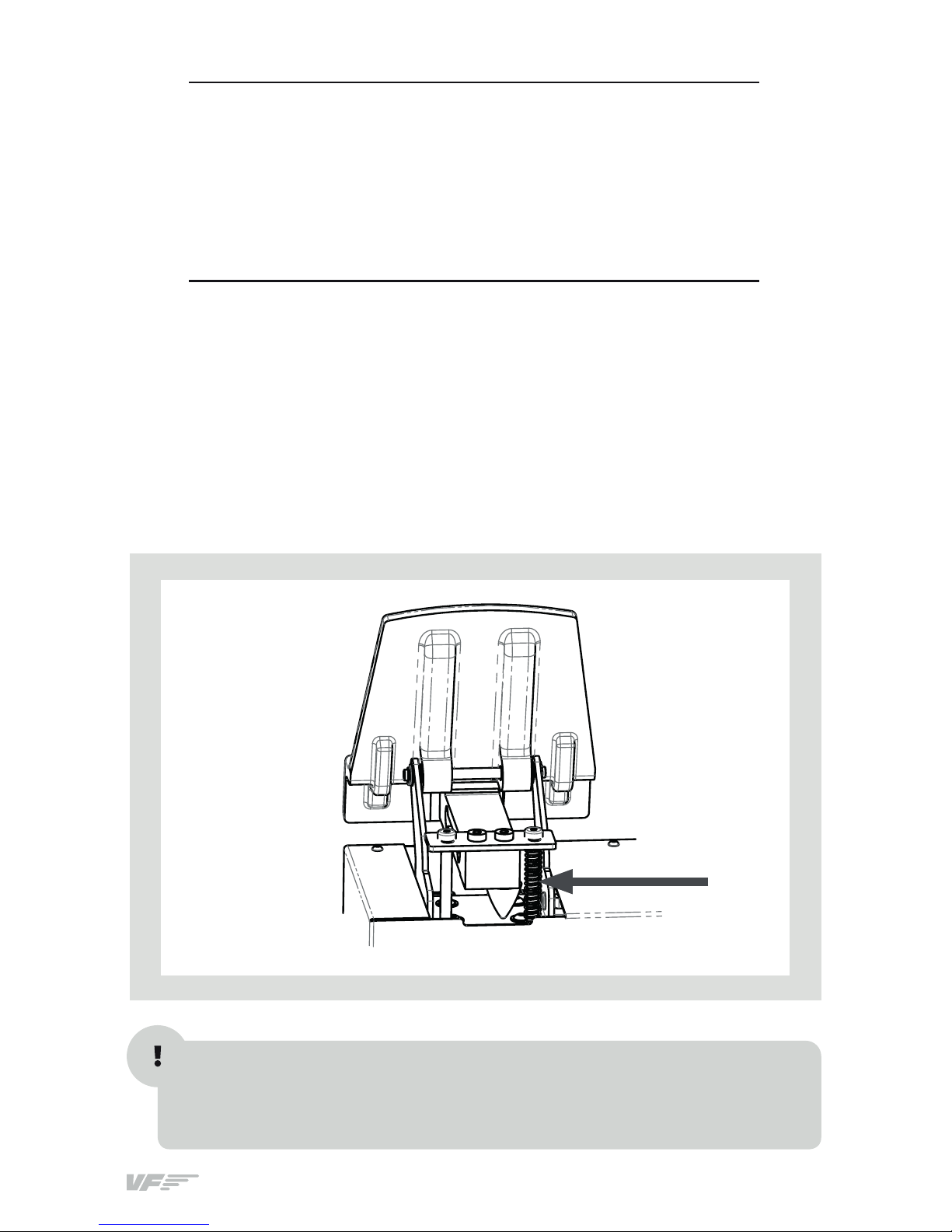
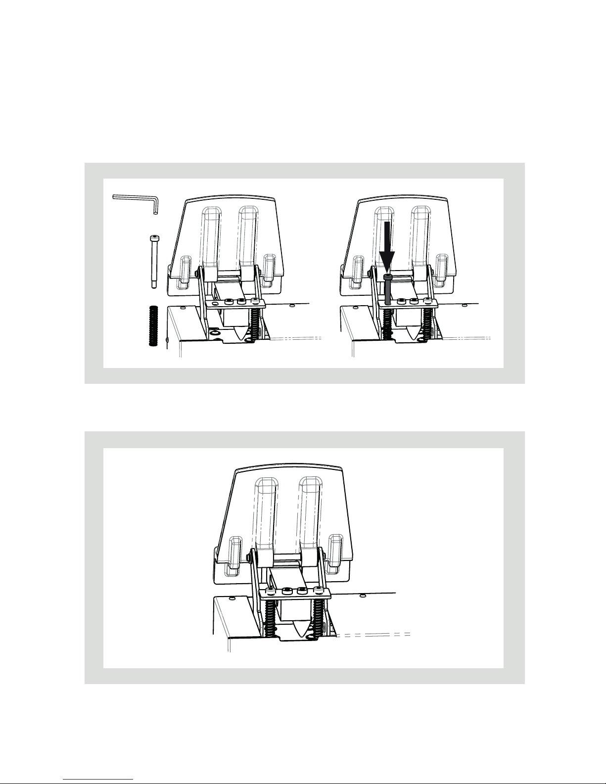
In the rear part of pedals there is a spring that oers resistance when the
brakes are pressed as you can see in the picture:
You can choose to use two springs for harder resistance or only one in order
to obtain a softer resistance. (Two more springs are supplied)
You will need an Allen wrench n. 3 (not included) to change the springs.
Page 9
98 –
1. Unscrew the external screw from back part of the pedal.
2. Add or remove the spring according to your preferences.
3. Place the screw to its original position.
4. Repeat the process with the other brake pedal.
Page 10
RUDDO | User guide
Rudder hardness
You can customize the rudder hardness adding or removing one of the
springs on every side of the rudder.
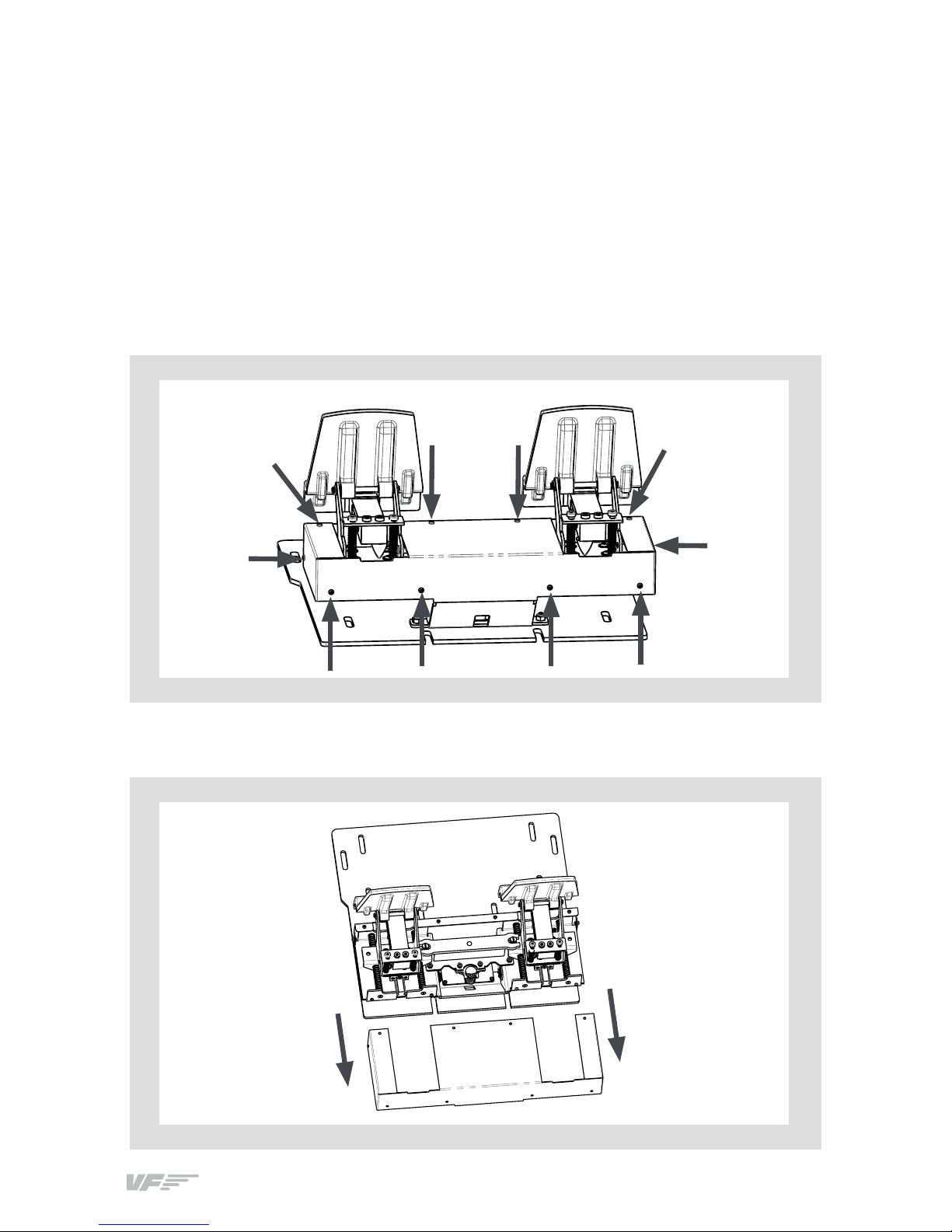
You will need to remove the black cover of the device using an Allen
wrench (number 2) (not included).
1. Remove the allen screws from the cover of RUDDO (To remove some
of the screws you will need to push the pedals with your hand).
2. Remove the cover carefully.
Page 11
1110 –
3. Remove the white axis guide using a screwdriver (not included).
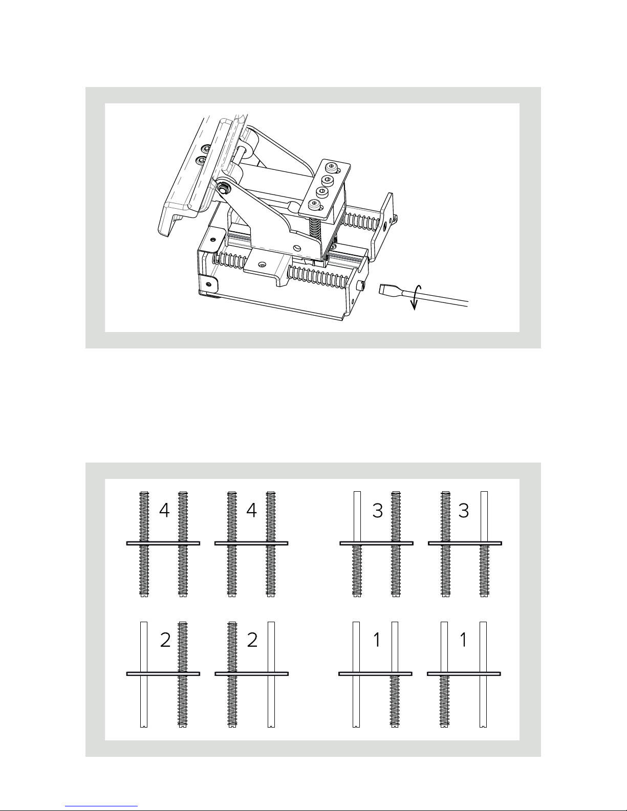
4. There are a total of 4 axis guides and 8 springs. Add or remove the
springs according your preferences.
You can decide 4 dierent combinations (see the gure bellow).
Number 4 corresponds to the strongest combination and Number 1
corresponds to the softer combination.
Page 12
RUDDO | User guide
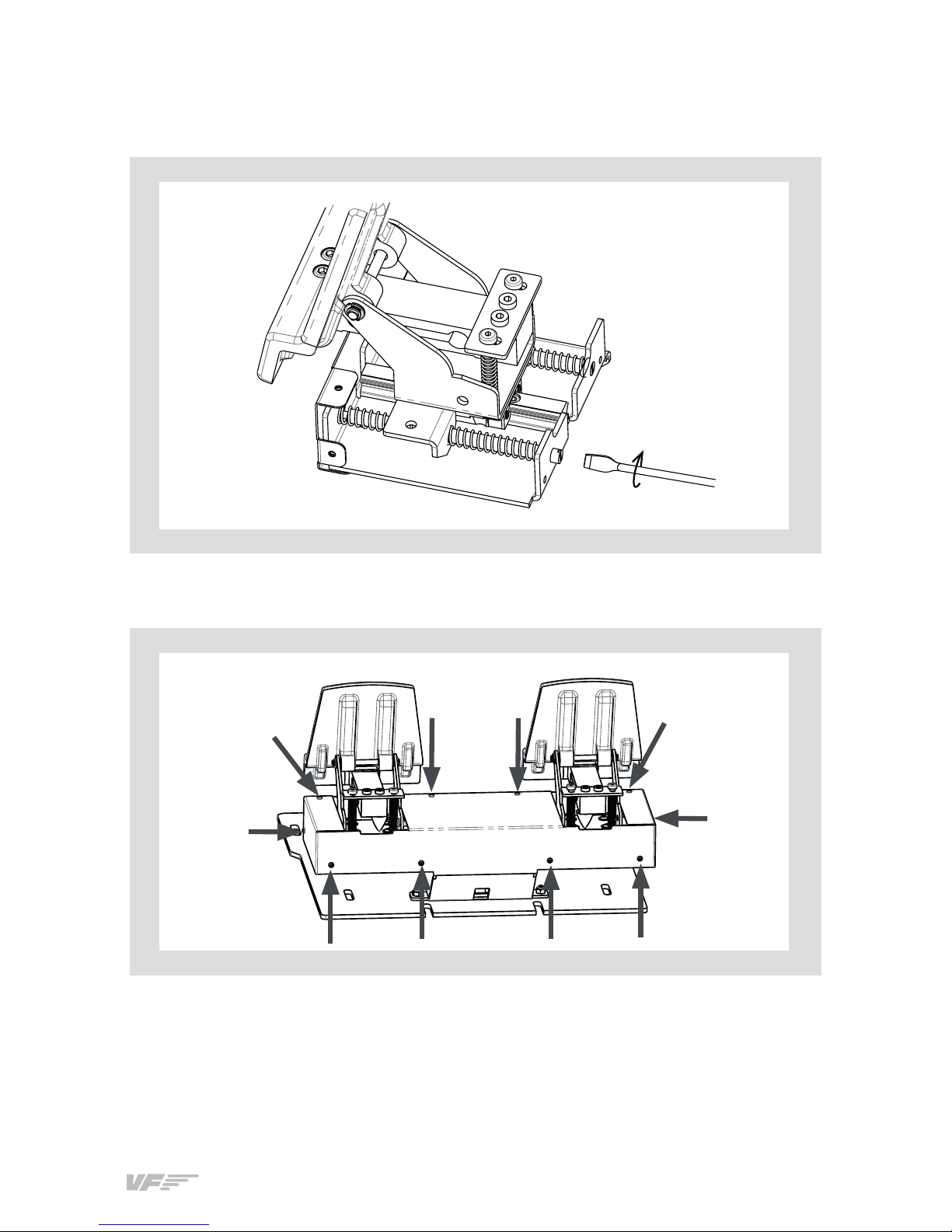
5. Screw the axis guide/s again using the screwdriver.
6. Place the cover again xing it with the screws removed at point 1.
Page 13
1312 –
4. RUDDO CALIBRATION
ON WINDOWS
(EXAMPLE BASED ON WINDOWS 7)
• Go to control panel, “Devices and printers”.
• In the “Devices and printers”, right click on “VirtualFly - RUDDO”.
• From the menu choose “Game controller settings”.
• In the Game controller window, double click on “VirtualFly - RUDDO”.
• Choose the “settings” tab.
• Click on “Calibrate”.
• In the “Game Device Calibration Wizard”, follow the steps shown. It's
very important that you follow step by step exactly as you read on
the screen.
• X axis corresponds to the rudder.
• X rotation corresponds to the left brake.
• Y rotation corresponds to the right brake.
• Once calibration is completed, go to the “Test” tab to check the correct
operation of the rudder, left brake and right brake.
• Click on “Apply”.
• Click “OK” to exit.
For a proper operation of RUDDO on Microsoft Flight Simulator (hereafter “MFS”) - Prepar3D and X-PLANE, prior calibration in the “Game
Controllers” section is required.
Page 14
RUDDO | User guide
5. RUDDO CONFIGURATION
ON MICROSOFT FLIGHT
SIMULATOR (MSF) AND
PREPAR3D
The user has two options in order to set the RUDDO with MFS-Prepar3D:
• Through the MFS-Prepar3D menu (5.1): This is the common procedu-
re in order to set any control device or joystick.
• Through the “VF-Test&Calibrate” Control Panel (5.2): "VF-
Test&Calibrate” is a Control Panel that makes a link between RUDDO
and MFS-Prepar3D. This Control Panel is an alternative of the RUDDO
settings used in MFS-Prepar3D, which provides a greater sensitivity
and dead zones for more realism.
Also, this control panel will let you limit the force that you apply on the
pedals-brake if you are not able to press the maximum force.
.. THROUGH THE MFS-PREPARD MENU
• From the main MFS-Prepar3D splash screen, choose the “Settings”
option and click on the “Controls” button.
• Check that “Enable controller(s)” option is activated.
• Click on the “Control axes” tab and select “VirtualFly – RUDDO” on the
dropdown list.
• Select “Rudder axis” in the list and press “Change Assignment”.
• Slide the rudder pedals taking care of not pressing the brakes. You will
see that the detected axe appears in textbox, then press "OK".
• Repeat the process for “Brake left axis” and “Brake right axis” of the list,
swivelling each time the corresponding pedal.
As "VF-Test&Calibrate” Control Panel receive input data from RUDDO
and then send it to MFS-Prepar3D, Keep in mind, that VF-Test&Calibrate
Control Panel has to remain ON when you use MFS-Prepar3D.
Page 15

1514 –
. THROUGH THE “VF-Test&Calibrate” CONTROL PANEL
Requirements
• FSUIPC module for MFS or Prepar3D.
• Disable joysticks on MSF-Prepar3D.
FSUIPC Installation
In case you already have FSUIPC installed in your MFS-Prepar3D you
can skip this step.
• Go to the “FSUIPC” folder from the memory stick provided with
RUDDO.
• Execute the setup program according your MFS version (FSX-
Prepar3D or FS2004).
• When the installer ask about registering, Click on “Not now”.
Disable joysticks on MSF-PreparD
When you connect any Joystick “game devices” in the computer, automatically MFS-Prepar3D makes assignment on all the buttons and
axes.
To disable these assignments, you have two options:
OPTION 1: Disable all the Joysticks “game devices” that you have connected in the computer:
• From the main MFS-Prepar3D splash screen, choose the “Settings”
option.
• Click on “Controls”.
• In the window that appears, go to the “Calibration” tab and disable
the “Enable controls” option.
OPTION 2: Disable only “Virtual-Fly RUDDO” assignments:
• From the main MFS-Prepar3D splash screen, choose the “Settings”
option.
• Click on “Controls”.
• In the window that appears go to the “Axes” tab.
• In the “Controller type” drop-down eld, select “VirtualFly – RUDDO”
• Now, from the list press “Delete Assignment” in all the RUDDO Axis.
In both options, when you have nished, Close MFS-Prepar3D to ensure that changes will be saved.
Page 16
RUDDO | User guide
“VF-Test&Calibrate” Control Panel Installation
• Inside the memory stick provided with RUDDO, you will nd a le
called “VF-TestCalibrate.exe”.
• Place the “VF-TestCalibrate.exe” le in your Flight Simulator computer. You can leave it in Desktop for example.
• Just duble click on the “VF-TestCalibrate.exe” le to execute it.
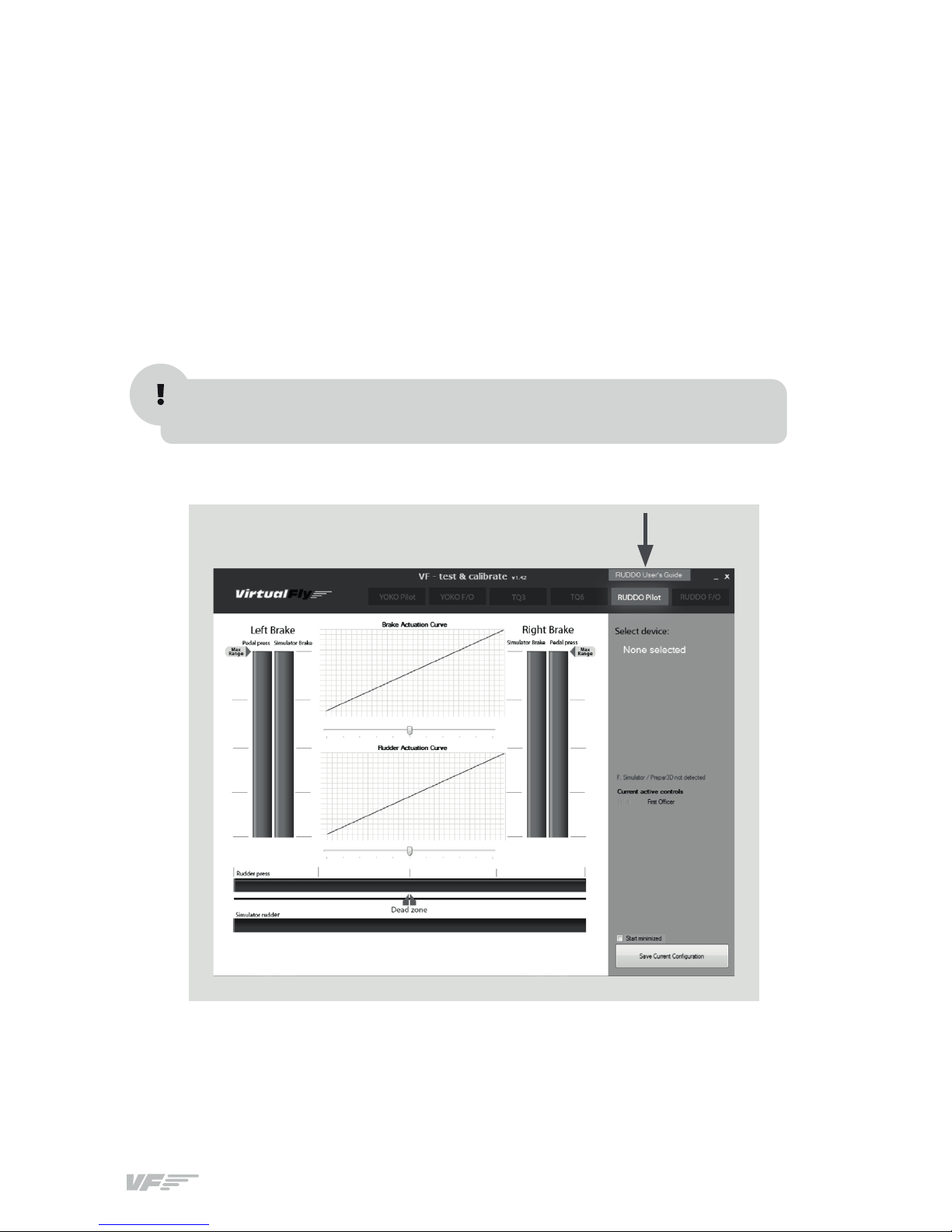
Using VF-Test&Calibrate
You will nd “VF-Test&Calibrate” user's guide inside the Control Panel.
See the arrow in the following gure.
Keep in mind, that VF-Test&Calibrate Control Panel has to remain ON
when you use MFS-Prepar3D.
Page 17
1716 –
6. CONFIGURATION
ON X-PLANE 10
• Execute X-Plane. Once is loaded, if a window appears prompting you
“select plane”, proceed loading a ight.
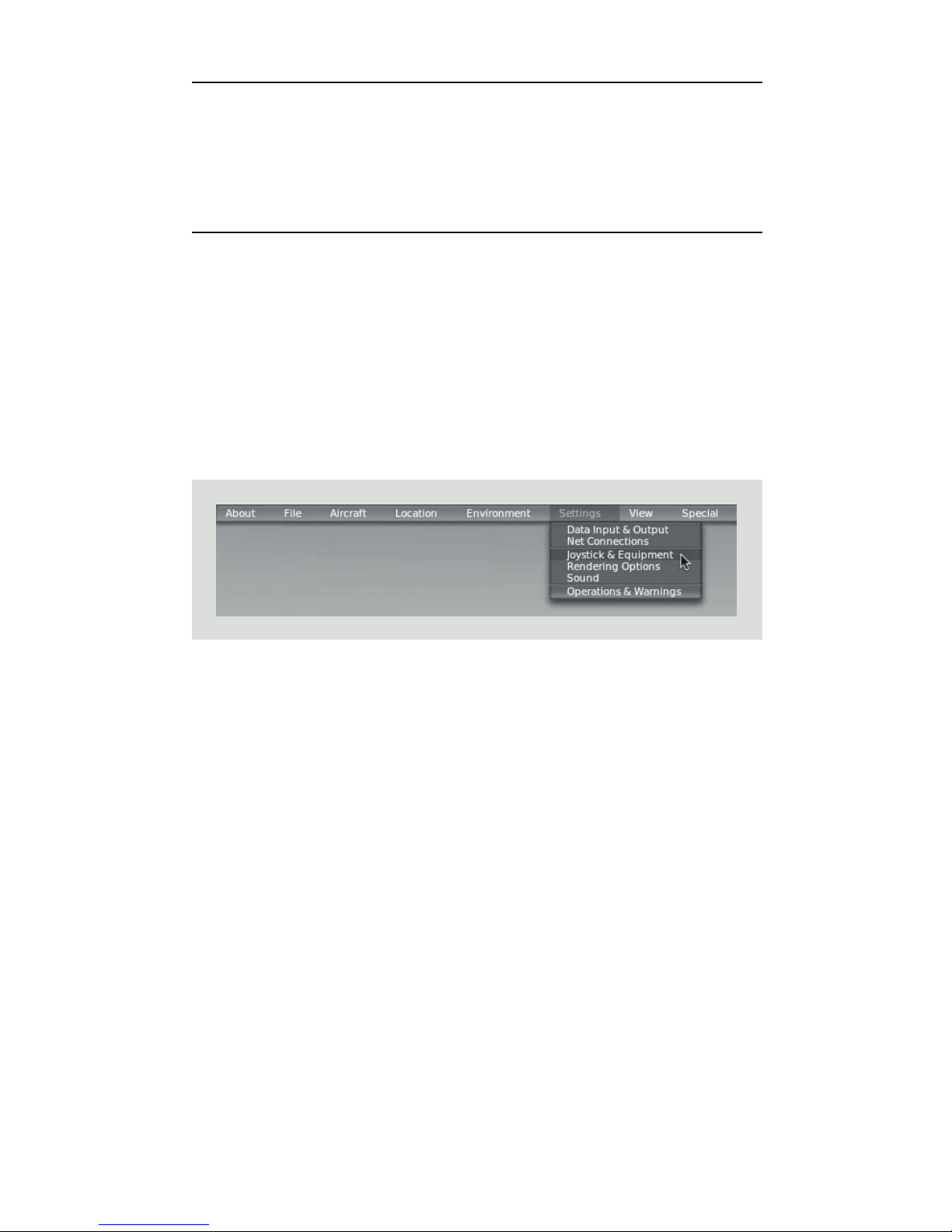
• Click on “Settings” at the top bar and then “Joystick & Equipment” as you
can see in the picture.
Axis assignment
• In the dialog box that appears, choose the “Axis” tab. Slide the pedals
from side to side to the maximum.
• One of bars should move. This bar will change from red to green
when the pedal reaches the maximum.
• In dropdown select “Yaw”.
• Repeat the process with the left brake actuating to the maximum.
Then select “Left toe brake” from the dropdown menu.
• Repeat the process with the right brake actuating to the maximum.
Then select “Right toe brake” from the dropdown menu.
Adjusting the sensibility
• Go to dead zone tab in “Joystick and equipment” dialog box.
• To adjust the sensibility of pedal axe move the slider “Yaw controlresponse”. Moving it to the right increases the sensibility of the axis.
• The sensibility brakes cannot be adjusted in X-Plane.
Page 18

RUDDO | User guide
Page 19

1918 –
Page 20

VIRTUAL FLY
HEADQUARTERS
c. Morales, 39 bajos
08029 Barcelona (Spain)
R & D CENTER - SHOWROOM
c. Maria Aurelia Capmany, 29
P. I. La Fàbrica
08297 Castellgalí (Spain)
T. (+34) 93 833 33 01
info@virtual-y.com
www.virtual-y.com
 Loading...