

Page 1
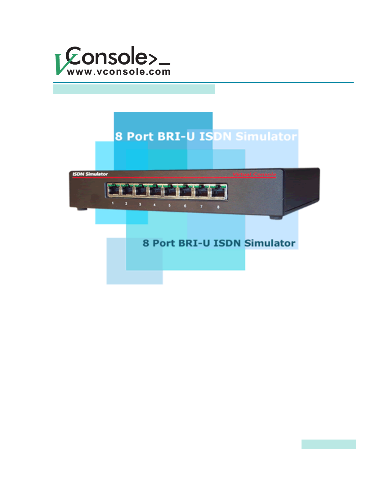
P/N: BRI-8U
User Manual Rev. 2.0
Copyright © 2001-2009, Virtual Console, LLC
All Rights Reserved
[email protected]
Page 2

Page 3

8 Port BRI-U ISDN Simulator
User Manual
Contents
Chapter 1: Important Information 3
General Disclaimer 3
Other Restrictions 3
Trademark Information 3
Patent information 3
Warranty 3
Limitation of Remedies and Damages 4
Important Safeguards 4
Regulatory Compliance 5
Chapter 2: Introduction 5
Unpacking 5
Fast Start for Advanced Users 5
About your ISDN Simulator 5
Chapter 3: Product Description 7
Ports / Interfaces 9
Power 9
Cabling 10
Controls 10
LEDs 10
Chapter 4: Controlling and Conguring your ISDN Simulator 10
Conguring the ISDN Simulator with ISDN Manager 11
Conguring ISDN Simulator via Terminal Server 13
SPID assignments 15
Upgrading Firmware 15
Troubleshooting 16
Chapter 5: AT commands conguration examples 17
Chapter 6: Specications 20
1
Page 4

8 Port BRI-U ISDN Simula-
User Manual
2
Page 5

8 Port BRI-U ISDN Simulator
This User Manual is applicable to the following product P/N: BRI-8U
User Manual
Chapter 1: Important Information
© 2002-2006 Virtual Console, LLC All Rights Reserved.
General Disclaimer
No part of this document can be reproduced or transmitted in any form or by any means, electronic or
mechanical, for any purpose without the written express permission from Virtual Console, LLC.
Under the law reproducing includes translating into another language or digital format.
As between the parties, Virtual Console, LLC retains title to, and ownership of, all proprietary rights with
respect to the software contained within its products. The software is protected by United States and
international copyright laws. Therefore, you must treat the software like any other copyrighted material.
Other Restrictions
You shall not and shall not allow any third party to decompile, disassemble, reverse-engineer or attempt to
reconstruct or discover any source code or underlying ideas or algorithms of the software by any means
whatsoever or remove any product.
Trademark Information
Virtual Console ® logo design is registered trademark in the United States and various other countries.
Microsoft®, Windows® are registered trademarks or trademarks of Microsoft Corporation.
All other trademarks are the property of their respective owners. Every effort has been made to ensure that the
information in this manual is accurate. Information in this document is the subject to change without notice.
Patent Information
The accompanying product is protected by one or more U.S. and foreign patents and patents pending held by
Virtual Console, LLC
Warranty
Virtual Console, LLC warrants its products to be free of defects in materials and factory workmanship for a
period of twelve (12) months from date of purchase.
This warranty does not apply to damage to products resulting from accident, misuse, service or modication by
anyone other than a Virtual Console, LLC authorized service facility/dealer.
The warranty is limited to the original purchaser and is not transferable. Any liability of Virtual Console or its
suppliers with respect to the product or the performance thereof under any warranty, negligence, strict liability
or other theory will be limited exclusively to product repair or replacement as provided above.
Except for the foregoing, the product is provided as is without warranty of any kind including without limitation,
any warranty of merchantability or tness for a particular purpose.
3
Page 6

User Manual
The entire risk of the quality and performance of the software programs contained in the system is with you.
Limitation of Remedies and Damages
Virtual Console, LLC, its agents, employees, suppliers, dealers and other authorized representatives shall
not be responsible or liable with respect to the product or any other subject matter related thereto under any
contract, negligence, strict liability or other theory for any indirect, incidental, or consequential damages,
including, but not limited to loss of information, business, or prots.
The law of certain states or nations does not permit limitation or exclusion of implied warranties and
consequential damages, so the above limitations, disclaimers, or exclusion may not apply to you. This
warranty gives you special legal rights. You may also have other rights that vary by state and nation.
Important Safeguards
Read and understand the following instructions before using the system:
Close supervision is necessary when the system is used by or near children. Do not leave unattended while in
use.
Always disconnect the system from power before cleaning and servicing and when not in use.
Do not spray liquids directly onto the system when cleaning. Always apply the liquid rst to a static free cloth.
Do not place this product onto unstable desk, cart or table. The product may fall causing serious damage to
the product.
Do not immerse the system in any liquid or place any liquids on it.
Do not disassemble this system (except as instructed in the manufacturers instructions). To reduce the risk of
shock and to maintain the warranty on the system, a qualied technician must perform service or repair work.
Connect this appliance to a grounded outlet.
Connect the system only to surge protected power outlets.
Keep ventilation openings free of any obstructions.
Unplug this product from the wall outlet and refer servicing to qualied service personnel under the following
conditions:
1. When the power supply adapter or plug is damaged or frayed.
2. If liquid has been spilled into the product.
3. If the product has been exposed to rain or water.
8. If the product has been dropped or the enclosure has been damaged.
9. If the product exhibits a distinct change in performance.
SAVE THESE INSTRUCTIONS
4
Page 7

8 Port BRI-U ISDN Simulator
User Manual
Regulatory Compliance
This equipment has been tested and found to comply with the limits for a Class A digital device, pursuant
to Part 15 of the FCC Rules. These limits are designed to provide reasonable protection against harmful
interference when the equipment is operated in a commercial environment. This equipment generates, uses
and can radiate radio frequency energy and, if not installed and used in accordance with the instruction
manual, may cause harmful interference in which case the user will be required to correct the interference at
his own expense.
Chapter 2: Introduction
ISDN Simulator is an eight port ISDN Switch which was designed to ease testing, demonstration and
development of ISDN Basic Rate CPE (TE) equipment. It simulates eight ISDN BRI lines reducing installation
and monthly charges from Telephone Company and provides full featured BRI lines for Voice, Data and Video
communications. ISDN simulator is equipped with “U” (4 wire) interfaces, allowing to connect eight devices
with “U” interface type.
Unpacking
Carefully unpack the items in the shipping box and verify that you have received the following:
1. ISDN Simulator unit
2. Wall mount power adapter
3. ISDN Manager Conguration Diskette
4. DB9F-DB9M 6-ft RS-232 cable for connection to a PC.
Fast Start for Advanced Users
1. Plug the power adapter into a power outlet, and connect the output power cable to the power jack on
your simulator.
2. Connect your devices to ISDN simulator with a straight CAT5 cable.
3. Connect the COM port on your PC to RS-232 port on simulator.
4. Use “ISDN Manager” application or AT commands to congure simulator.
About your ISDN Simulator
Virtual Console’s “BRI-8U” ISDN simulator is an ISDN switch with eight BRI “U” interfaces, whichprovides call
switching services for Basic Rate Interface (BRI) terminal equipment. All our ISDN simulators conform to the
ISDN architecture and to individually programmable switch types (Table 1). Our products are extensively used
with ISDN routers, modems, ISDN telephones, faxes and commercial H.320 videoconferencing products.
5
Page 8
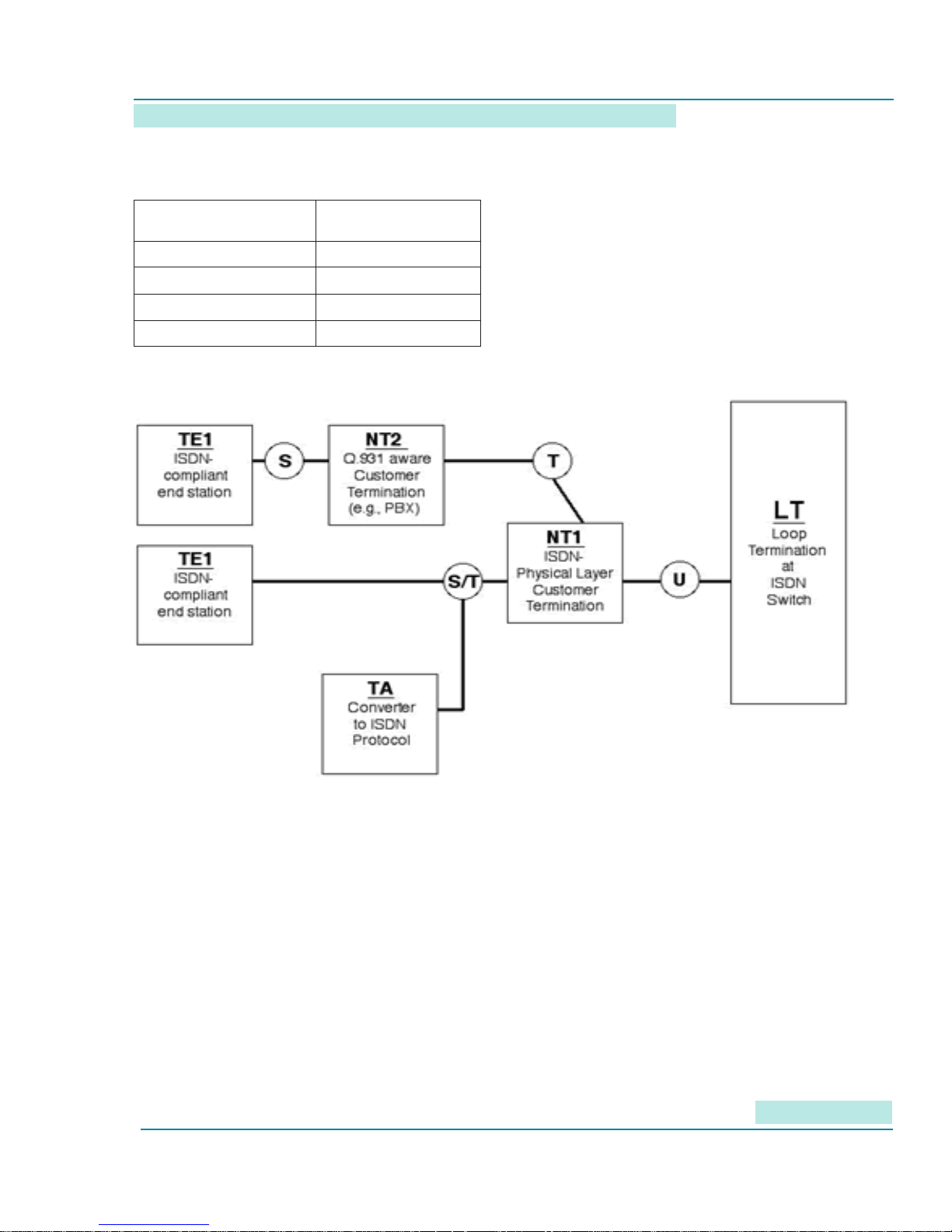
Table 1: Switch Types Emulated
Switch Type SPID required
National ISDN-1 Yes
NET3 No
AT&T 5ESS Optional
Nortel DMS-100 Yes
Figure 1: ISDN Functional Architecture
User Manual
The ISDN simulator appears to the customer-side Functional Groupings as the Loop Termination (LT) at
the telephone central ofce. These Functional Groupings, examples of which are shown in, include ISDN-
compliant Terminal Equipment (TE1), Network Terminations (NT1 and NT2) and Terminal Adapters (TA).
To an NT1 or NT2, the simulator provides the “U” interfaces.
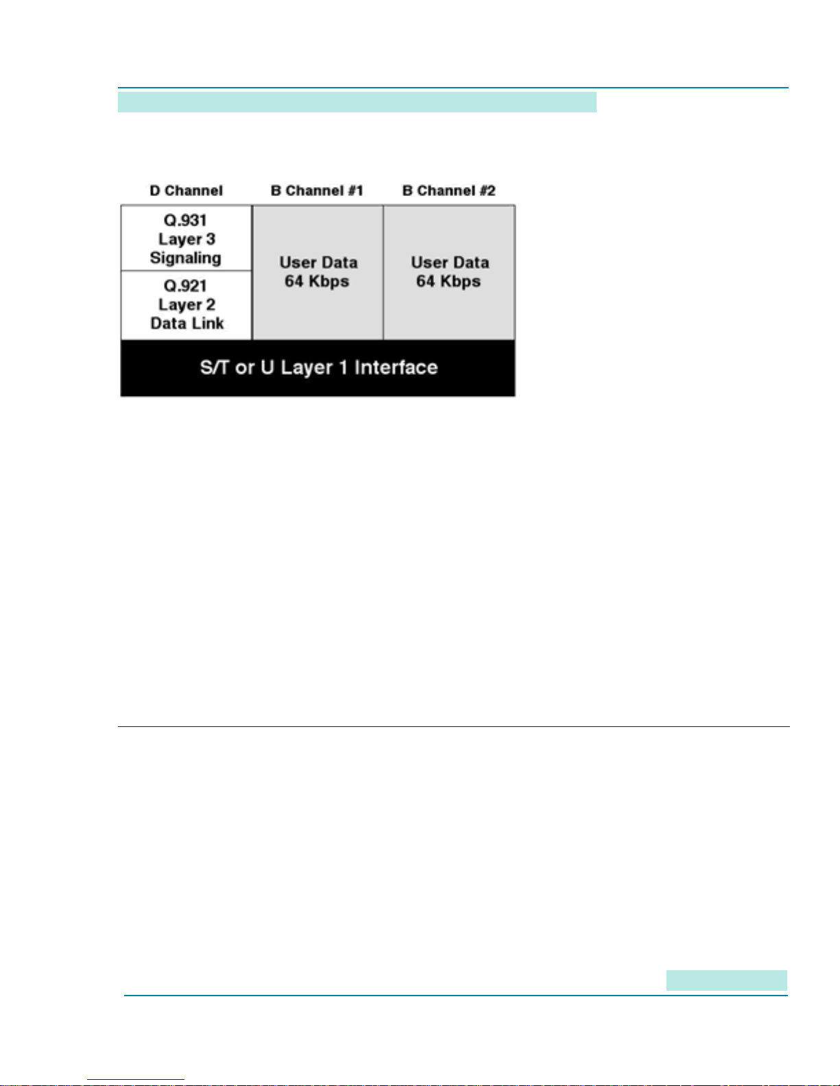
Over these physical interfaces ow the protocols described in Figure 2.
While Q.931, the ISDN primary “dialing” protocol, usually is used to set up dynamic ISDN calls, ISDN simulator
also supports semi-permanent “nailed up” B channels that act like private leased lines. Refer to ISDN Manager
chapter for conguring “Leased Line” mode.
6
Page 9
8 Port BRI-U ISDN Simulator
Figure 2: ISDN Protocol Stack
Selecting a ISDN Switch type
User Manual
To use ISDN simulator you must set the switch type. Use drop down menu in ISDN Manager application to
select appropriate BRI switch type. Selected BRI switch type must match the one congured on ISDN device.
Once that is done, you will always need to set the phone numbers (i.e., DN) and, if the congured switch type
requires it, the SPID numbers.
“Caller ID”, or, in formal ISDN terminology, “calling number identication presentation”, is always enabled and a
part of standard call setup procedure dened in Q.931 standard.
Chapter 3: Product Description
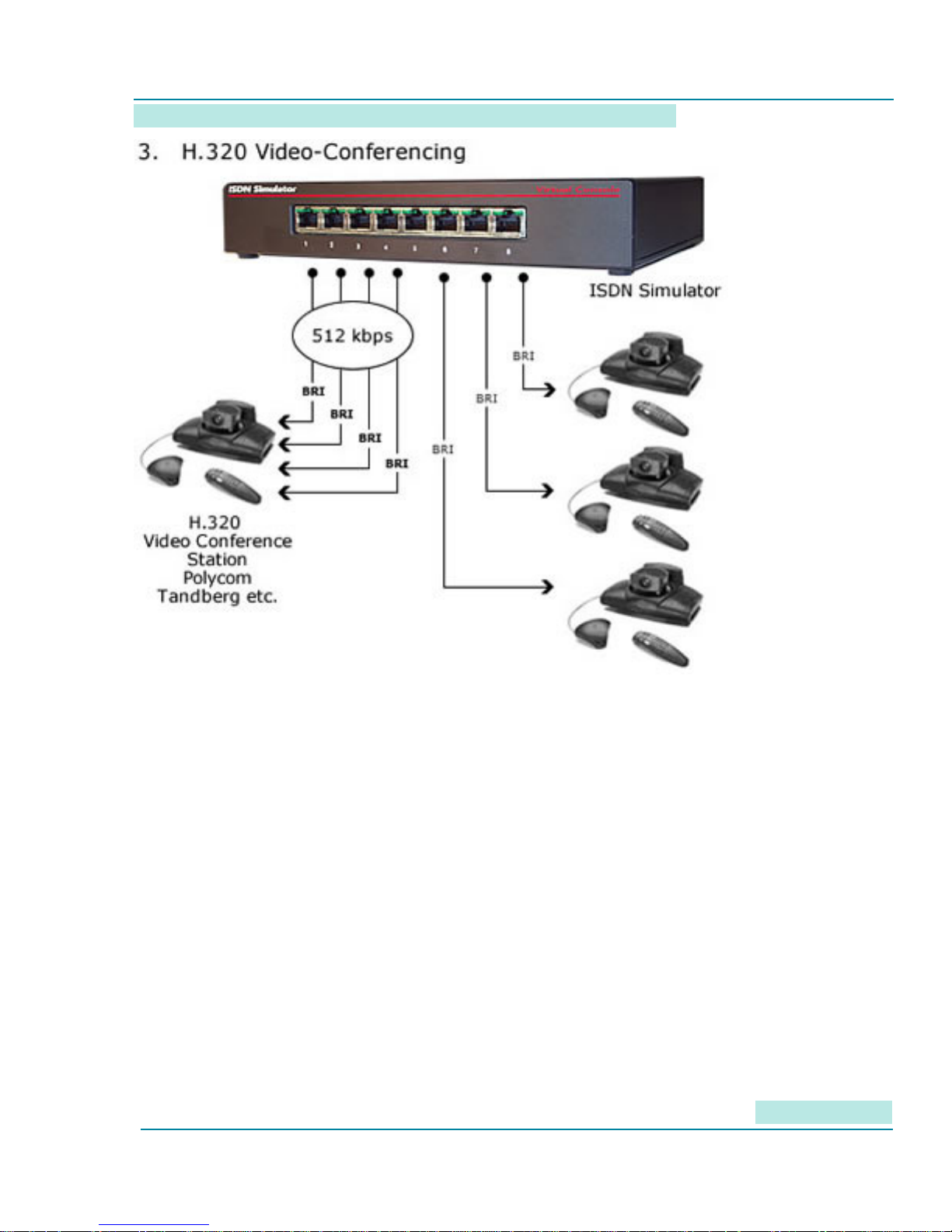
The Virtual Consoles ISDN simulator provides a “Telco in a box” for a variety of device testing scenarios
including ISDN routers, modems, ISDN telephones, faxes and H.320 video conferencing stations Commercial
H.320 videoconferencing equipment will set up from one to four physical BRI Interfaces delivering up to
512kbps bandwidth for each site.
7
Page 10
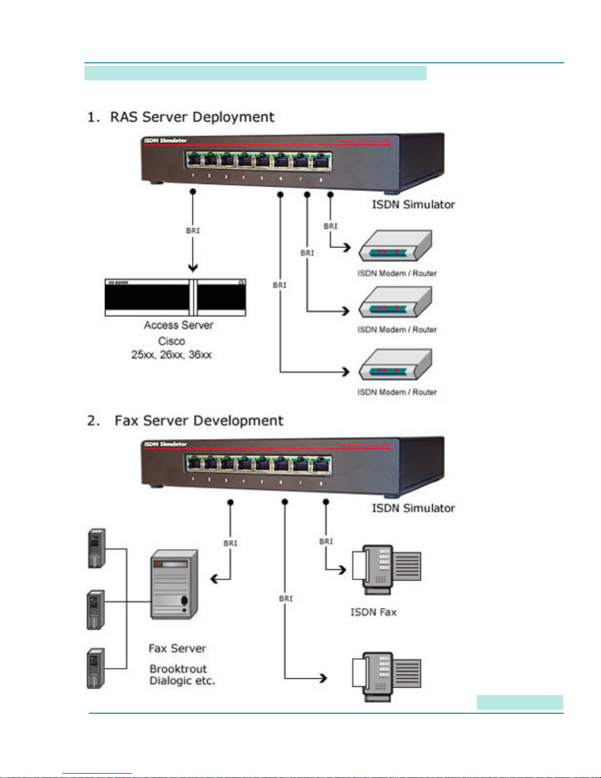
Figure 3: Functional Applications of the Virtual Console Simulator
User Manual
8
Page 11
8 Port BRI-U ISDN Simulator
User Manual
The device has the most common connectors and indicators on its front panel. In a rack installation with
routers, you would typically want the front panel on the same side as the router interface connectors. Less
frequently used connectors and switches are on the back. Do note that the “Reset” button function can be
invoked remotely through the ISDN Manager interface.
Ports / Interfaces
The simulator has eight separate BRI “U” interfaces
Power
ISDN Console simulator is powered from a 9-12 DC or AC, 500 mA supply that plugs into a standard
household outlet. International power supplies are available if you need to use the device in a country that
does not use 120 VAC 60 Hz.
Note: Power supply may be slightly warm when operating.
The simulator does not provide inline power to connected ISDN devices. They will need independent power
sources.
9
Page 12

User Manual
Cabling
Straight-through RS-232 cable with DB9 M/F connectors is supplied with each ISDN Simulator for the ISDN
Manager or console management. To connect ISDN devices to the simulator, also use a straight-through CAT3
or CAT5 cable with RJ45 connectors.
Controls
A hardware “Reset” button is on the back panel of the ISDN Simulator. You can also Reboot ISDN Simulator
remotely using ISDN Manager application or AT command (ATZ) sent via console port.
The button on simulator is labeled as “Reset”; the button in ISDN Manager is labeled as “Reboot”.
LEDs
Each of the eight RJ45 ports has two integrated Green LEDs (LEFT and RIGHT). The left LED on port 1 is
always “ON” to indicate presence of power, even when no device is connected. On all other ports, the right
LED turns solid GREEN when a device is connected at the physical layer. The left LED on all other ports, dark
until layer 2 initializes, turns green when layer 2 is up.
As layer 3 activity begins, the left and right LEDs will begin to blink. If the switch type requires SPIDs and a
SPID is invalid for a B channel, the associated channel LED -- left for B-channel 1, right for B-channel 2 -- will
blink slowly.
If either SPIDs are not required, or the correct SPID is used, once the B-channel 1 is up, the left LED will begin
blinking rapidly. In like manner, when the B-channel 2 comes up, the right LED will begin to blink rapidly.
Chapter 4: Controlling and Configuring your ISDN
Simulator
Your simulator is controlled by ISDN Manager application or AT commands. Connect to this COM port on your
PC to RS-232 port on simulator with the supplied 6-foot straight-through DB9 cable. We recommend that you
use the ISDN Manager application, which provides a graphic interface with several convenient click buttons.
In test racks, you may nd it more convenient to control simulator with AT commands.
10
Page 13
8 Port BRI-U ISDN Simulator
User Manual
Conguring the ISDN Simulator with ISDN Manager
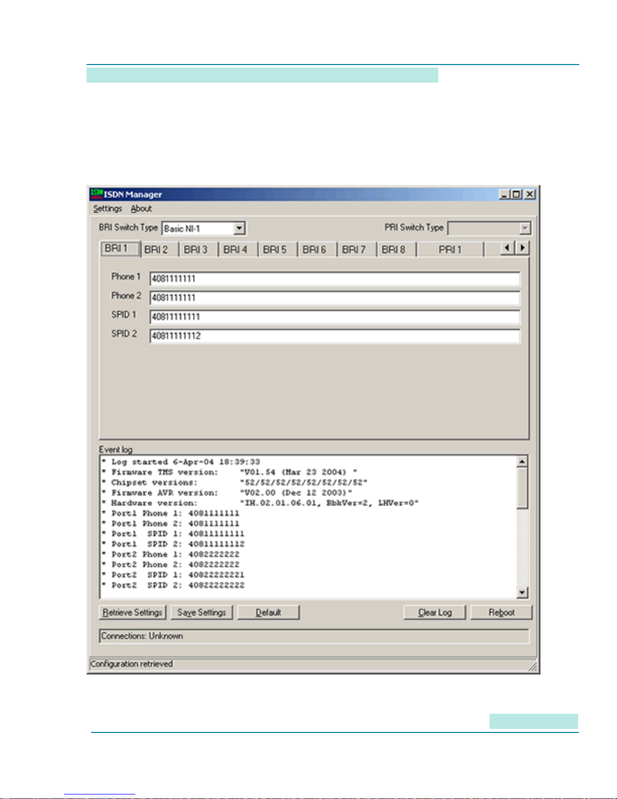
Virtual Console’s “ISDN Manager” application is the principal means of conguring and controlling ISDN
simulators. It is a Windows application supported for Windows 2000 and Windows XP. The ISDN Manager
version for this product also supports 8-port BRI U, as well as PRI, simulators.
Figure 4: ISDN Manager Screens
11
Page 14
User Manual
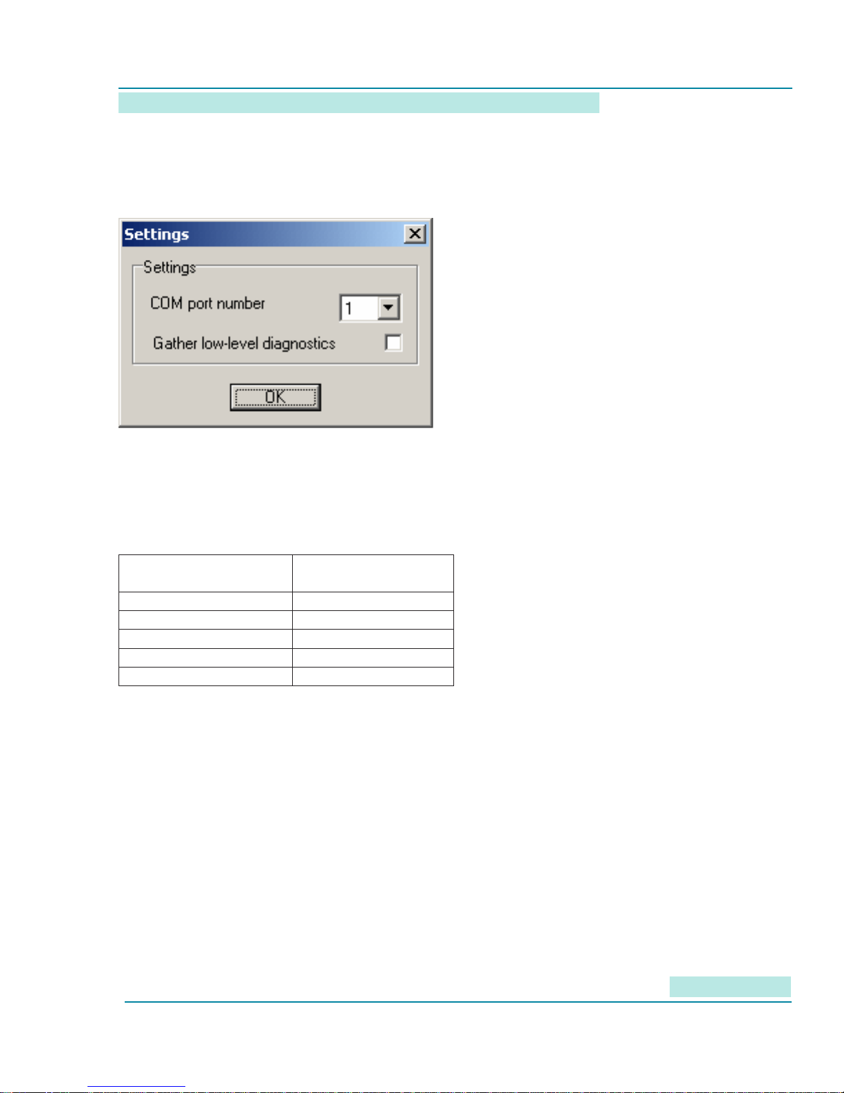
When you bring up ISDN Manager, you can set the appropriate COM port for it to communicate with the
simulator with the settings’ tab (Figure 5). The “gather low-level diagnostics” is used only when working with
the factory.
Figure 5: Setting the COM port for ISDN Manager
Your PC COM port must be congured with the settings in Table 2
Table 2: COM port settings for ISDN Manager
Parameter Value
Baud rate 115200 bps
Data bits 8
Parity None
Stop bits 1
Flow Control Hardware
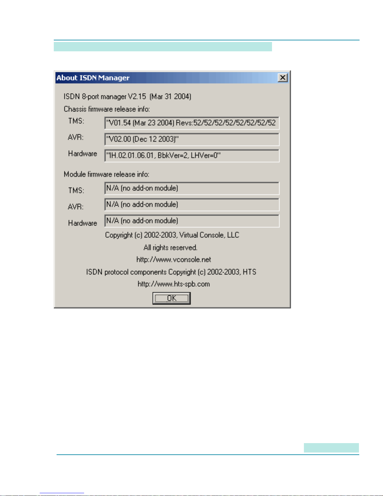
Once you are in communications with the ISDN simulator, you can click the “About” tab to check rmware and
software versions (Figure 6). See “Upgrading Firmware” for the upgrade procedure, which will give you a
new version of the TMS code. The AVR and Hardware elds in the gure are for factory use.
12
Page 15
8 Port BRI-U ISDN Simulator
Figure : Version information from ISDN Manager About tab
User Manual
On the main screen, you set the “switch-type” (see Table 1).
To set individual port characteristics, click on the appropriate “Port” tab. The screen will then show the current
phone number and, when applicable, SPID number (see Table 6) for each B channel on the port. You can then
set the values as required.
If you need to congure a B channel in “nailed up”, “semi-permanent”, or “dedicated line” mode, check the
appropriate box at the top of the ISDN Manager screen.
Conguring ISDN Simulator via Terminal Server
Many test environments control all devices from a single point, using a terminal server to connect to all devices
at a remote site. You can control the ISDN simulator in this manner. You must set the asynchronous interface
on the terminal server to the values in Table 3, and use the commands in Table 5.
13
Page 16
User Manual
Table 3: Interface Settings for Reverse Telnet
Parameter Value
Baud rate 115200 bps
Data bits 8
Parity None
Stop bits 1
Flow Control Hardware
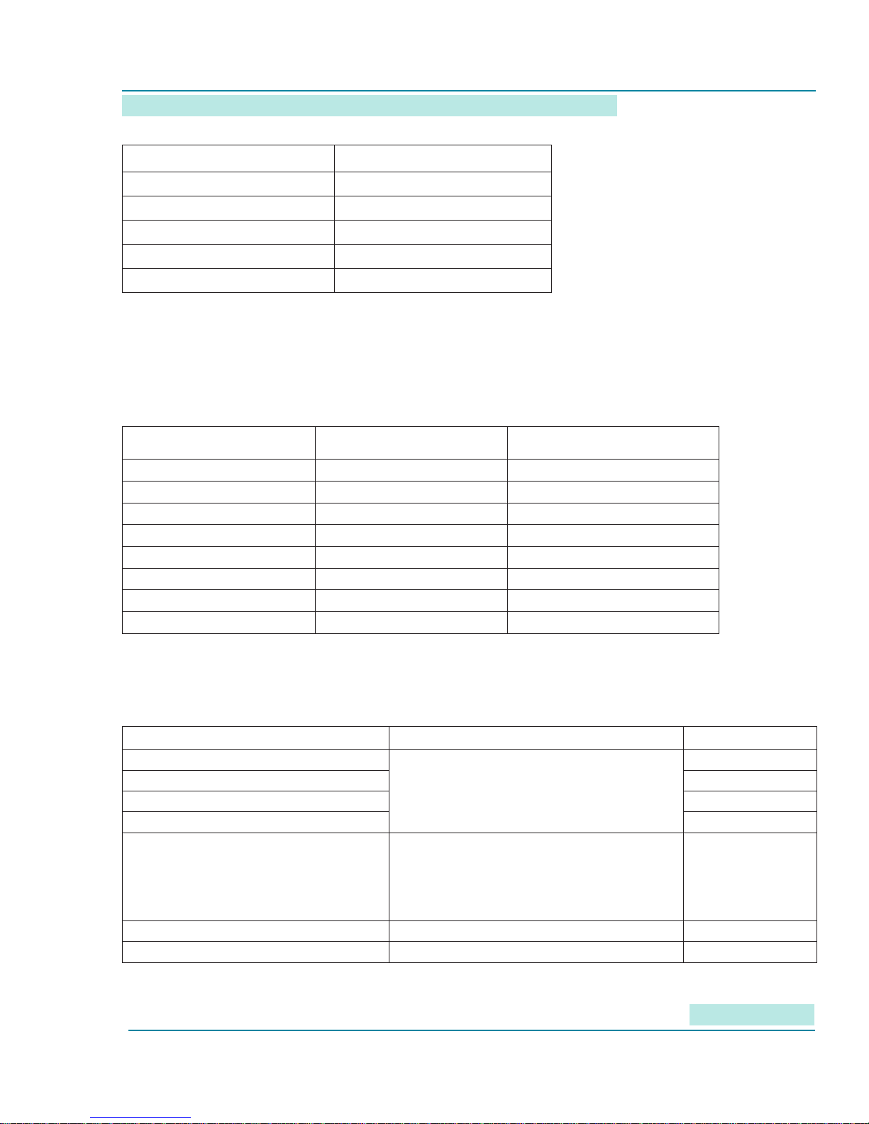
From a terminal server, since you cannot press display buttons, modem-style AT commands must be issued
for all functions.
Since these commands apply to B-channels, you need to understand which B channel numbers apply to which
physical U interface (Table 4).
Table 4: Conguring the ISDN Simulator via Terminal Interface
BRI physical interface First B-channel number Second B-channel number
Port 1 0 8
Port 2 1 9
Port 3 2 10
Port 4 3 11
Port 5 4 12
Port 6 5 13
Port 7 6 14
Port 8 7 15
Once you understand the logical numbering, you can complete the commands (Table 5). The “x” parameter in
this table refers to the BRI channel number in Table 4.
Table 5: Conguring the Simulator via Terminal Interface, where “x” is the B-channel number
Function Additional Parameters Command
Get Phone number on B-channel “x”
Get SPID number on B-channel “x” ATPx?
Set Phone number on B-channel “x” ATNx =”value”
Set SPID number on B-channel “x” ATPx =”value”
Get/Set switch type
(in concert with SPID settings):
Save Conguration AT&W
Reboot ATZ
“x” is the B-channel number from 0 to 15
0 = either NI-1 or Net3
- NI-1: SPID set
- NET3: no SPIDs (””)
64 = 5ESS (SPIDs optional)
512 = DMS-100
ATNx?
ATO
14
Page 17
8 Port BRI-U ISDN Simulator
It is recommended to reboot (ATZ) after any conguration changes.
User Manual
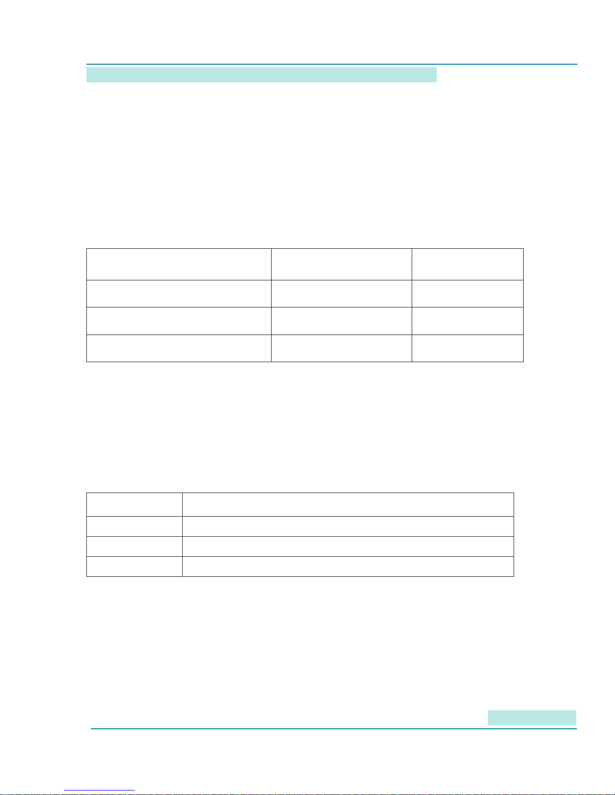
SPID assignments
Some ISDN switches, or provider implementations of switches, require Service Provider Identiers (SPID).
You need to know the type required for your reference conguration.
You can use any SPID numbering scheme that matches your requirement. We support three types of SPID
numbering (Table 6). Whenever you change the SPID, reboot the simulator and preferably the TE device.
Table 6: SPID Formats
SPID format Switch type Comment
All SPIDs are “0”
Matches any SPID on the TE side
All SPID are empty Supported by NET3 only Standard
Any sequence of 40 digits.
Supported by NI-1, DMS-
100, 5ESS
Supported by NI-1, DMS-
100, 5ESS
Troubleshooting use
Standard
Upgrading Firmware
Virtual Consoles will periodically publish rmware and software upgrades.
Visit www.vconsole.com for latest versions. When you download new rmware, check if there is a newer
version of ISDN Manager and upgrade that as well.
Table 8: Firmware Upgrade
File Function & comments
XLOAD.EXE Firmware loader
XXXXX.XMD Firmware, where XXXXXX is a platform specic designation.
DEV.CFG Device default conguration le
To load new rmware with the XLOAD program, connect a COM port of a PC to the console port of the
simulator. The XLOAD program must have exclusive use of the COM port; no other application may use it
while the upgrade program is running.
Example:
XLOAD.EXE P2US.XMD /Com:1 /Cfg:DEV.CFG
at the Windows DOS command prompt. In this example, the Virtual Console device is connected to COM1
port and loads the default settings from the DEV.CFG le.
15
Page 18

User Manual
Troubleshooting
Be systematic in your troubleshooting, from the environmental and then bottom-up from layer 1 upwards.
Table 8: Symptoms and Recommended Actions
Left LED on Port 1 does not light
Port’s Right LED does not light up
after a device is connected.
Port’s Left LEDs do not light up after
a device is connected.
Left/Right LEDs are solid Green, and
do not start blinking after the placing
a call
Check power cabling, and the power supply. Verify
the outlet has power.
1. Check port 1, left LED. If it is OFF, check power
cabling, and the power supply
2. Check that the ISDN device is powered up
3. Check device cabling. Verify interface type.
3. Try another port
4. Contact technical support
1. Check that the ISDN device is powered up
2. Try another port (other than port 1)
3. Contact technical support
1. Verify phone numbers dialed
2. Verify switch type and SPID settings
3. Verify ISDN device conguration
4. Try another port
5. Contact technical support
16
Page 19

8 Port BRI-U ISDN Simulator
User Manual
Chapter 5: AT command configuration examples
Assigning Phone Numbers
Port 1: (42211001, 42211001)
Port 2: (42211002, 42211002)
Port 3: (42211003, 42211003)
Port 4: (42211004, 42211004)
Port 5: (42211005, 42211005)
Port 6: (42211006, 42211006)
Port 7: (42211007, 42211007)
AT Conguration script:
atn0=”42211001”
atn1=”42211002”
atn2=”42211003”
atn3=”42211004”
atn4=”42211005”
atn5=”42211006”
atn6=”42211007”
atn7=”42211008”
atn8=”42211001”
atn9=”42211002”
atn10=”42211003”
atn11=”42211004”
atn12=”42211005”
atn13=”42211006”
atn14=”42211007”
atn15=”42211008”
at&w
atz
Conguring NET3 switch type without SPID numbers
atp0=””
atp1=””
atp2=””
atp3=””
atp4=””
atp5=””
atp6=””
atp7=””
atp8=””
atp9=””
atp10=””
atp11=””
atp12=””
atp13=””
atp14=””
atp15=””
ato=0
at&w
atz
17
Page 20

Conguring NI-1 switch type that matches any SPID numbers
atp0=”0”
atp1=”0”
atp2=”0”
atp3=”0”
atp4=”0”
atp5=”0”
atp6=”0”
atp7=”0”
atp8=”0”
atp9=”0”
atp10=”0”
atp11=”0”
atp12=”0”
atp13=”0”
atp14=”0”
atp15=”0”
ato=0
at&w
atz
Conguring 5ESS switch type with SPID numbers
User Manual
atp0=”02422110010101”
atp1=”02422110020101”
atp2=”02422110030101”
atp3=”02422110040101”
atp4=”02422110050101”
atp5=”02422110060101”
atp6=”02422110070101”
atp7=”02422110080101”
atp8=”02422110010102”
atp9=”02422110020102”
atp10=”02422110030102”
atp11=”02422110040102”
atp12=”02422110050102”
atp13=”02422110060102”
atp14=”02422110070102”
atp15=”02422110080102”
ato=64
at&w
atz
18
Page 21

8 Port BRI-U ISDN Simulator
User Manual
Conguring 5ESS switch type without SPID numbers
atp0=””
atp1=””
atp2=””
atp3=””
atp4=””
atp5=””
atp6=””
atp7=””
atp8=””
atp9=””
atp10=””
atp11=””
atp12=””
atp13=””
atp14=””
atp15=””
ato=64
at&w
atz
Conguring DMS-100 switch type (same as 5ESS with SPIDS, except ATO=512)
atp0=”02422110010101”
atp1=”02422110020101”
atp2=”02422110030101”
atp3=”02422110040101”
atp4=”02422110050101”
atp5=”02422110060101”
atp6=”02422110070101”
atp7=”02422110080101”
atp8=”02422110010102”
atp9=”02422110020102”
atp10=”02422110030102”
atp11=”02422110040102”
atp12=”02422110050102”
atp13=”02422110060102”
atp14=”02422110070102”
atp15=”02422110080102”
ato=512
at&w
atz
19
Page 22

User Manual
Chapter 6: Specifications
Power Adapter: Input: 110/220 VAC Output: 9 VDC, 600mA. 2.5mm jack
U Interface: RJ-45, 8-pin modular jack
U Interface protocol: 2B1Q (2 Binary 1 Quaternary)
Maximum cable drop: 1600 meters
RS-232 Interface: DB-9 Female
Storage Temperature: -40 to +55C
Operating Temperature: 0 to 50 C
Humidity Max: 75%
Dimensions: 8.75”L X 6.5”W X 1.6”H
Weight: 1 lb (500g)
20
Page 23

8 Port BRI-U ISDN Simulator
Copyright © 2001-2009, Virtual Console, LLC
All Rights Reserved
User Manual
21
 Loading...