

Page 1

Service Managed Gateway
Configuring the Analog
Modem
User Guide
Issue 1.2
Date 27 January 2004
Page 2

Configuring the Analog Modem Table of Contents
© Virtual Access Ltd.
1.0 Introduction ..................................................................................................... 3
2.0 Setting up and Configuring the Analog Modem........................................... 5
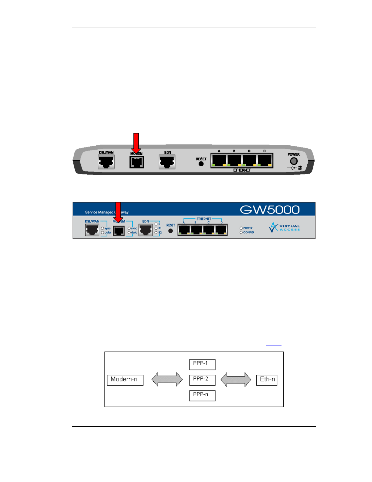
2.1 Setting up the physical port connection.................................................... 5
2.1.1 The physical port connection for the GW4000 Series................................. 5
2.1.2 The physical port connection for the GW5000 Series................................. 5
2.2 Configuring the analog modem .................................................................. 5
2.3 Using the modem as the primary WAN interface ..................................... 6
2.3.1 Enabling the modem interface.................................................................... 6
2.3.2 Setting up the PPP WAN interface ............................................................. 6
2.3.3 Setting up PPP- and IP-related interfaces .................................................. 6
2.3.4 Setting up Modem Call-related options....................................................... 6
2.3.5 Setting up Routing ...................................................................................... 7
2.4 Using the modem as a backup WAN interface .......................................... 7
2.5 Using the modem as a management interface .......................................... 7
2.5.1 Setting up the analog modem for dial-out management ............................. 8
2.5.2 Setting up the analog modem for dial-in management ............................... 8
2.6 SMG Boot-Mode Maintenance over V.92.................................................... 8
3.0 Modem Monitoring and Diagnostics ........................................................... 10
3.1 Active Data Connections ........................................................................... 10
3.2 Call History ................................................................................................. 11
3.3 Connection Monitor ................................................................................... 12
3.4 Modem Events............................................................................................ 13
Page 3

Configuring the Analog Modem Introduction
© Virtual Access Ltd. Page 3 of 14
1.0 Introduction
The Virtual Access Service Managed Gateway (SMG) GW-4000 and GW-5000
product range is optionally fitted with an analog modem. This document
describes the configuration and use of the analog modem.
The modem conforms to ITU V.92 specification, which is an enhancement of
the V.90 modem. The V.92 modem offers two main functions over the V.90
modem:
1. Quick connect: the connection time may be reduced by 50% compared
to the V.90 modem
2. Faster upstream rate: upload speeds may reach 48kbps, compared to
31.2kbps with the V.90 modem. It is also capable of data speeds of up to
56kbps downstream.
The following standards are supported:
Data modem
V.92 / V.90
V.34
V.32bis
V.32
V.29
V.22bis
V.22
V.22 Fast Connect
V.23
V.21
Bell212a
Bell103
Data compression
V.44
V.42bis and MNP5
V.42 LAPM and MNP2-4 error correction
Page 4

Configuring the Analog Modem Introduction
© Virtual Access Ltd. Page 4 of 14
The analog modem interface on SMG products is available for use in several
scenarios.
As a normal WAN interface, the analog modem can be used in the same
way other WAN interfaces such as DSL and ISDN are used
As a backup WAN interface, the analog modem can be set up to come
into operation if the primary WAN interface becomes unusable for some
reason.
As an out-of-band management interface, the analog modem can access
the SMG management functions by dialing into the SMG, for example
using the Virtual Access Activator product. It is also possible for the
SMG to dial-out via the analog modem interface under some conditions.
A number of low-level maintenance functions are available by dialing the SMG
analog modem interface if the SMG does not boot up correctly, or otherwise
fails to start up properly.
Page 5
Configuring the Analog Modem Setting up and Configuring the Analog Modem
© Virtual Access Ltd. Page 5 of 14
2.0 Setting up and Configuring the Analog Modem
2.1 Setting up the physical port connection
To set up the physical modem interface, connect your analog line cable to your
phone line wall-socket on one side and to the SMG RJ-11 modem port on the
other side.
2.1.1 The physical port connection for the GW4000 Series
2.1.2 The physical port connection for the GW5000 Series
2.2 Configuring the analog modem
The modem is configured as a logical interface modem-n, where n is the
interface number (for example, modem-0).
The modem interface has the following configuration attributes:
Enabled: Yes, No
The logical modem interface is then connected to a PPP interface through
configuration of the PPP WAN interface as described in section 2.3.2 below.
Page 6

Configuring the Analog Modem Setting up and Configuring the Analog Modem
© Virtual Access Ltd. Page 6 of 14
2.3 Using the modem as the primary WAN interface
2.3.1 Enabling the modem interface
Using the expert view of the WEB configuration, go to Interfaces folder, select
modem-n folder (where n is the interface number, e.g. modem-0). Set Enabled
field to yes, click Update and saved to flash link
2.3.2 Setting up the PPP WAN interface
In the Interfaces folder, select a ppp-n interface that you want to run over the
modem line (e.g. ppp-1), select Wan Interface page, select modem (n) for the
WAN interface, (where n is the modem logical interface number, e.g. modem
(0)). Click Update and save to flash link.
2.3.3 Setting up PPP- and IP-related interfaces
PPP and IP options are set up the same way as for other WAN interfaces, the
description is outside the scope of this document.
2.3.4 Setting up Modem Call-related options
Select the folder Interfaces - ppp-n - interface modem folder. Select Call
page. Configure outgoing call destination number (called phone number),
configure Permissions to one of the following:
Call: to make outgoing PPP calls over this modem interface
Answer: to accept incoming PPP calls over this modem interface
Call and Answer: to both make and accept PPP calls over this modem
interface
Set the inactivity timer, minimum and maximum call duration.
If necessary, click the Advanced button to configure the modem call advanced
options:
Call retries: number of times an outgoing call will be re-tried is the call
fails to establish
Call retry delay: time between individual call retries
Carrier delay: number of seconds the modem will wait for carrier before
reporting failure to connect to remote modem
Click the Update button. Then click the save to flash link.
Page 7

Configuring the Analog Modem Setting up and Configuring the Analog Modem
© Virtual Access Ltd. Page 7 of 14
Note: Although it is possible to configure more than one PPP interface for
incoming calls, when a call comes in over the modem interface only the first
compatible PPP interface will answer the call – it is compatible if it has Answer
Permissions and WAN interface set to modem-n logical interface.
2.3.5 Setting up Routing
Select System - IP folder. Select the default route page. Configure the next
hop to be the selected PPP-n interface. Alternatively, select the static routes
page and configure the static routes for PPP-n interface.
2.4 Using the modem as a backup WAN interface
The analog modem as Backup WAN interface works as follows: If PPP-x is
configured as primary WAN interface (using for example ADSL) and for some
reason becomes un-operational for a specified amount of time, an outgoing
PPP connection is established on PPP-y which is configured as backup.
To configure the modem interface and WAN backup:
Go through the steps described in section 2.3
to configure the modem interface
for primary WAN access. The outgoing call destination number should be the
backup ISP number. The call permission should be set to “call” or “call and
answer”.
Enter the following commands from serial console connected to SMG:
Modem Interface Dial Backup Enabled = Yes
Modem Interface Backed Up By = <Interface name> (e.g. PPP-2)
Modem Interface Backup Restore Timeout = <seconds> - time for the
primary interface to be down before routing switches to backup interface
2.5 Using the modem as a management interface
The analog modem can be used for management in two cases:
1. making outgoing, Activator-initiated PPP calls over the modem interface
2. accepting an incoming modem call on the managed SMG from the
remote Activator.
Page 8

Configuring the Analog Modem Setting up and Configuring the Analog Modem
© Virtual Access Ltd. Page 8 of 14
2.5.1 Setting up the analog modem for dial-out management
Follow the steps described in section 2.3 to set up the modem for use as
primary WAN interface, select call for permissions and configure the outgoing
destination number to be the phone number to which the managed SMG is
connected.
The IP routing table must be configured to route traffic destined to Activator
over PPP-1.
2.5.2 Setting up the analog modem for dial-in management
Follow the steps described in section 2.3 to set up the modem for use as
primary WAN interface. Use PPP-8 for PPP interface. Select answer for call
permissions. The IP routing table must be configured to route traffic destined to
Activator over PPP-8.
2.6 SMG Boot-Mode Maintenance over V.92
If SMG fails to boot up or is placed into boot-loader mode, it is possible to use a
number of low level maintenance functions by making a modem call to SMG
accepted on modem interface. The SMG will automatically connect an incoming
modem call and present the user with the management menu. An example
session is shown below.
Connected to Virtual Access Service Managed Gateway.
Press ENTER for the command prompt
#>
?
Select one of the following help menus:
help general
help debug
help flash
Page 9

Configuring the Analog Modem Setting up and Configuring the Analog Modem
© Virtual Access Ltd. Page 9 of 14
help fpga
help memory
help adsl
help hub/ethernet
help all
or enter a letter followed by '*' for a search
Page 10

Configuring the Analog Modem Document Change Log
© Virtual Access Ltd. Page 10 of 14
3.0 Modem Monitoring and Diagnostics
3.1 Active Data Connections
When a modem call is established it can be monitored using the Active Data
Connections applet. To view the Active Data Connections monitor, open the
SMG home page and select Status Æ Active Data Connections. The
following information is available for monitoring:
Field name Field description
Interface name
Descriptive PPP interface name (e.g. “PPP-1 Testing”)
Interface port PPP-n (n – PPP interface number)
Interface address xxx.xxx.xxx.xxx – ppp interface address
Call Direction Incoming or outgoing call direction
Connection Type Modem
State
Channels in use
Called number Called party number for outgoing call direction
Called sub-address
Calling number Calling party number for incoming call direction
Calling sub-address
Connect time Call establishment data and time
Duration Call current duration
Transmitted
packets
Number of transmitted packets
Transmitted bytes Number of transmitted bytes
Received packets Number of received packets
Received bytes Number of received bytes
Initial IP source
Initial IP destination
Page 11

Configuring the Analog Modem Document Change Log
© Virtual Access Ltd. Page 11 of 14
3.2 Call History
Analog modem historical usage can be monitored using the Call History applet.
On the SMG home page, select Status Æ Call History. Click the desired day
and hour, or click zoom in if you need to see a more detailed view of the
history. The detailed call view includes the following fields:
Outgoing / Incoming Data Call
Field name Description
Interface PPP interface (e.g. PPP-1)
Title Interface descriptive name (e.g. “Testing”)
Duration Call duration
Connect
Date and time the connected was established
Disconn Date and time the connection was terminated
Channel Local interface (e.g. modem-0)
Called no Called number for outgoing calls
Source IP
Destination
Protocol
Data In Number of bytes and packets received
Data Out Number of bytes and packets received
Cause Termination cause (e.g. Normal clearing)
Page 12

Configuring the Analog Modem Document Change Log
© Virtual Access Ltd. Page 12 of 14
3.3 Connection Monitor
The connection monitor enables you to view the current status of IPCP,
CHAP/PAP and LCP protocol, as well and modem data status.
On the SMG home page, select Advanced Æ Connection Monitor. The select
Modem Interface.
The boxes will represent the current status of the monitored entities as follows:
Page 13

Configuring the Analog Modem Document Change Log
© Virtual Access Ltd. Page 13 of 14
3.4 Modem Events
The SMG WEB Trace applet can be used to monitor the log of modem-related
events. To access it, on the SMG home page, select Advanced Æ
Diagnostics. Click the Trace Analyzer button. Click Select to select custom
events. Add MODEM to the list of selected events, and then click Start Trace.
Now modem call events are displayed in the trace window.
Page 14

Configuring the Analog Modem Document Change Log
© Virtual Access Ltd. Page 14 of 14
The following table lists all possible modem events:
Severity Text Meaning
INFO Dial (<called number>) Outgoing modem call in progress to
called number
INFO Incoming Ring Incoming ring signal detected by
modem interface on the line
INFO Incoming Call Answering SMG answered the incoming modem
call, connection negotiation in
progress.
INFO <Incoming | Outgoing
>Call Connected <DCE
speed>
Modem call connected with displayed
line speed in bits per second.
NOTICE <Incoming | Outgoing
>Call Failed <DCE
reason>
Modem call failed to establish –DCE
reason is given
(e.g. NO DIALTONE)
NOTICE Dial failed (<reason>).
Retrying (n)
Outdoing modem call dial failed, DCE
reason is given
(e.g. BUSY) and a dial command is
being re-tried, n is the retry number.
NOTICE Dial Failed (outgoing calls
not allowed)
Outgoing dial did not proceed,
because the PPP port permission is
not set to make outgoing calls
NOTICE Dial Failed (no number
configured)
Outgoing dial did not proceed,
because the PPP port dial neighbor
originate address (called number) is
not configured
INFO <Incoming | Outgoing
>Call Local Disconnect
Modem call has been locally
terminated
INFO <Incoming | Outgoing
>Call Remote Disconnect
<reason>
Modem call remotely terminated, DCE
reason is given (e.g. NO CARRIER).
 Loading...