

Page 1

Issue:
1.4
Date:
12 May 2016
GW2020 Series User Manual
Page 2

_______________________________________________________________________________________________________
Table of Contents
1 Introduction ................................................................................................. 8
1.1 Document scope ....................................................................................... 8
1.2 Using this documentation ........................................................................... 9
2 GW2020 hardware specification ................................................................. 11
2.2 Hardware features .................................................................................. 11
2.3 Serial ports ............................................................................................ 11
2.4 GSM and LTE technology .......................................................................... 14
2.5 Power supply .......................................................................................... 14
2.6 Router dimensions .................................................................................. 15
2.7 Compliance ............................................................................................ 15
2.8 Operating temperature range ................................................................... 16
2.9 Antenna ................................................................................................. 16
2.10 Components ........................................................................................... 16
2.11 Inserting a SIM card ................................................................................ 18
2.12 Connecting the SIM lock .......................................................................... 18
2.13 Connecting the ante nna ........................................................................... 18
2.14 Powering up the GW2020 Series router...................................................... 18
2.15 Powering up the GW2024P Series router .................................................... 18
2.16 Reset button .......................................................................................... 19
3 GW2020 Series LED be haviour .................................................................... 20
3.1 Main LED behaviour................................................................................. 20
3.2 GW2020 Ethernet port LED behaviour ....................................................... 21
4 GW2024P Series LED behaviour.................................................................. 22
4.1 Main LED behaviour................................................................................. 22
4.2 Ethernet LED behaviour ........................................................................... 23
5 GW2028 Series LED behaviour .................................................................... 24
5.1 Main LED behaviour................................................................................. 24
5.2 Ethernet port LED behaviour .................................................................... 25
6 Factory configuration extraction from SIM card ......................................... 26
7 Accessing the router ................................................................................... 27
7.1 Configuration packages used .................................................................... 27
7.2 Accessing the router over Ethernet using the web interface .......................... 27
7.3 Accessing the router over Ethernet using an SSH client ............................... 28
7.4 Accessing the router over Ethernet using a Telnet client .............................. 29
7.5 Configuring the password ......................................................................... 29
7.6 Configuring the password using the web interfa ce ....................................... 29
7.7 Configuring the password using UCI .......................................................... 30
7.8 Configuring the password using package o ptions......................................... 30
7.9 Accessing the device using RADIUS authentication ...................................... 31
7.10 Accessing the device using TACACS+ authentication ................................... 32
_______________________________________________________________________________________________________
© Virtual Access 2016
GW2020 Series User Manual
Issue: 1.4 Page 2 of 309
Page 3

_______________________________________________________________________________________________________
Table of Contents
7.11 SSH ...................................................................................................... 36
7.12 Package dropbear using UCI ..................................................................... 37
7.13 Certs and private keys ............................................................................. 38
7.14 Configuring a router’s web server ............................................................. 38
7.15 Basic authentication (httpd conf) .............................................................. 43
7.16 Securing uhttpd ...................................................................................... 44
8 Configuring Dynamic DNS ........................................................................... 45
8.1 Overview ............................................................................................... 45
8.2 Configuration packages used .................................................................... 45
8.3 Configuring Dynamic DNS using the web interfac e ...................................... 45
8.4 Dynamic DNS using UCI........................................................................... 47
9 System settings .......................................................................................... 49
9.1 Configuration package used ..................................................................... 49
9.2 Configuring system properties .................................................................. 49
9.3 System settings using UCI ....................................................................... 53
9.4 System diagnostics ................................................................................. 54
10 Upgrading router f i r m wa re ......................................................................... 56
10.1 Upgrading firmware using the web interface ............................................... 56
10.2 Upgrading firmware using CLI .................................................................. 57
11 Using the Command Line Interface ............................................................. 59
11.1 Overview of some common commands ...................................................... 59
11.2 Using Unified Configuration Interface (UCI) ................................................ 62
11.3 Configuration files ................................................................................... 67
11.4 Configuration file syntax .......................................................................... 67
12 Management configuration settings ........................................................... 69
12.1 Activator ................................................................................................ 69
12.2 Monitor .................................................................................................. 69
12.3 Configuration packages used .................................................................... 69
12.4 Autoload: boot up activation ..................................................................... 69
12.5 Autoload packages .................................................................................. 70
12.6 Autoload using UCI ................................................................................. 72
12.7 HTTP Client: configuring activation using the web interface .......................... 73
12.8 Httpclient: Activator configuration using UCI .............................................. 75
12.9 User management using UC I .................................................................... 76
12.10 Configuring the managem ent user password using UCI ............................. 77
12.11 Configuring management user password using package options ................. 78
12.12 User management using UC I ................................................................. 78
12.13 Configuring user access to specific web pages ......................................... 79
13 Configuring an Ethernet interface ............................................................... 80
13.1 Configuration packages used .................................................................... 80
_______________________________________________________________________________________________________
© Virtual Access 2016
GW2020 Series User Manual
Issue: 1.4 Page 3 of 309
Page 4

_______________________________________________________________________________________________________
Table of Contents
13.2 Configuring an Ethernet interface using the web interface ............................ 80
13.3 Interface configura tion using UCI .............................................................. 89
13.4 Configuring port maps ............................................................................. 92
13.5 Port map packages .................................................................................. 92
13.6 Interface diagnostics ............................................................................... 94
14 DHCP server and DNS configuration (Dnsmasq) ......................................... 96
14.1 Configuration package used ..................................................................... 96
14.2 Configuring DHCP and DNS using the web interface .................................... 96
14.3 Configuring DHCP and DNS using UCI ...................................................... 103
14.4 Configuring DHCP pools using UCI ........................................................... 105
14.5 Configuring static leases using UCI .......................................................... 106
15 Configuring VLAN ..................................................................................... 108
15.1 Maximum number of VLANs supported .................................................... 108
15.2 Configuration package used ................................................................... 108
15.3 Configuring VLAN using the web interface ................................................ 108
15.4 Viewing VLAN interface settings .............................................................. 111
15.5 Configuring VLAN us ing the UCI interface ................................................. 111
16 QoS: VLAN 802.1Q PCP tagging ................................................................ 112
16.1 Configuring VLAN PCP tagging ................................................................ 112
17 QoS: type of service .................................................................................. 115
17.1 QoS configuration overview .................................................................... 115
17.2 Configuration packages used .................................................................. 115
17.3 Configuring QoS using the web interface .................................................. 115
17.4 Configuring QoS us ing UCI ..................................................................... 117
17.5 Example QoS configurations ................................................................... 121
18 Configuring static routes .......................................................................... 122
18.1 Configuration package used ................................................................... 122
18.2 Configuring static routes using the web interface ...................................... 122
18.3 Configuring IPv6 routes using the web interface ....................................... 123
18.4 Configuring routes using command line ................................................... 124
18.5 IPv4 routes using UCI ............................................................................ 124
18.6 IPv4 routes using package options .......................................................... 125
18.7 IPv6 routes using UCI ............................................................................ 125
18.8 IPv6 routes using packages options ......................................................... 125
18.9 Static routes diagnostics ........................................................................ 126
19 Configuring BGP (Border Gateway Protocol) ............................................ 127
19.1 Configuration package used ................................................................... 127
19.2 Configuring BGP using the web interface .................................................. 127
19.3 Configuring BGP using UCI ..................................................................... 130
19.4 Configuring BGP using packages options .................................................. 131
_______________________________________________________________________________________________________
© Virtual Access 2016
GW2020 Series User Manual
Issue: 1.4 Page 4 of 309
Page 5

_______________________________________________________________________________________________________
Table of Contents
19.5 View routes statistics ............................................................................. 132
20 Configuring a mobile connection .............................................................. 133
20.1 Configuration package used ................................................................... 133
20.2 Configuring a mobile connection using the web interface ............................ 133
20.3 Configuring a mobile connection using UCI ............................................... 138
20.4 Mobile status using UCI ......................................................................... 138
21 Configuring mobile manager..................................................................... 140
21.1 Configuration package used ................................................................... 140
21.2 Configuring mobile manager using the web interface ................................. 140
21.3 Configuring mobile manager using UCI .................................................... 141
21.4 Configuring a roaming interface template via the web interface .................. 143
21.5 Monitoring SMS .................................................................................... 143
21.6 Sending SMS from the router ................................................................. 143
21.7 Sending SMS to the router ..................................................................... 143
22 Configuring Multi-WAN ............................................................................. 144
22.1 Configuration package used ................................................................... 144
22.2 Configuring Multi-WAN using the web interface ......................................... 144
22.3 Multi-WAN traffic rules ........................................................................... 149
22.4 Configuring Multi-WAN using UCI ............................................................ 149
22.5 Multi-WAN diagnostics ........................................................................... 150
23 Automatic operator selection .................................................................... 153
23.1 Configuration package used ................................................................... 153
23.2 Configuring automatic operator selection via the web interface ................... 153
23.3 Configuring via UCI ............................................................................... 172
23.4 Configuring No PMP + roa ming using UCI ................................................. 176
23.5 Automatic operator selection diagnostics v ia the web interface ................... 179
23.6 Automatic operator selection diagnostics v ia UCI ...................................... 179
24 Configuring IPSec ..................................................................................... 182
24.1 Configuration package used ................................................................... 182
24.2 Configuring IPSec using the web interface ................................................ 182
24.3 Configuring IPSec using UC I ................................................................... 189
24.4 Configuring an IPSec template for DMVPN via the web interface ................. 193
24.5 Configuring an IPSec template to use with DMVPN .................................... 200
24.6 IPSec diagnostics using the web interface ................................................ 202
24.7 IPSec diagnostics using UCI ................................................................... 202
25 Configuring a GRE interface ...................................................................... 203
25.1 Configuration packages used .................................................................. 203
25.2 Creating a GRE connecti on using the web interface ................................... 203
25.3 GRE configuration using command line .................................................... 207
25.4 GRE configuration using UCI ................................................................... 207
_______________________________________________________________________________________________________
© Virtual Access 2016
GW2020 Series User Manual
Issue: 1.4 Page 5 of 309
Page 6

_______________________________________________________________________________________________________
Table of Contents
25.5 GRE configuration using package options ................................................. 207
25.6 GRE diagnostics .................................................................................... 208
26 Dynamic Multipoint Virtual Private Network (DMVPN) ............................. 210
26.1 Prerequisites for configuring DMVPN ........................................................ 210
26.2 Advantages of using DMVPN ................................................................... 210
26.3 DMVPN scenarios .................................................................................. 211
26.4 Configuration packages used .................................................................. 213
26.5 Configuring DMVPN using the web interface ............................................. 213
26.6 DMVPN diagnostics ................................................................................ 215
27 Configuring firewall .................................................................................. 218
27.1 Configuration package used ................................................................... 218
27.2 Configuring firewall using the web interface ............................................. 218
27.3 Configuring firewall using UCI ................................................................. 230
27.4 IPv6 notes ........................................................................................... 232
27.5 Implic ations of DROP vs. REJECT ............................................................ 232
27.6 Connection tracking .............................................................................. 233
27.7 Firewall examples ................................................................................. 234
28 Configuring SNMP ..................................................................................... 241
28.1 Configuration package used ................................................................... 241
28.2 Configuring SMNP using the web interface................................................ 241
28.3 Configuring SNMP us ing c ommand line .................................................... 246
29 Configuring VRRP ..................................................................................... 253
29.1 Overview ............................................................................................. 253
29.2 Configuration package used ................................................................... 253
29.3 Configuring VRRP using the web interface ................................................ 253
29.4 Configuring VRRP using UCI ................................................................... 255
30 Configuring Multicasting using PIM and IGMP interfaces.......................... 257
30.1 Overview ............................................................................................. 257
30.2 Configuration package used ................................................................... 257
30.3 Configuring PIM and IGMP using the web interface .................................... 257
30.4 Configuring PIM and IGMP using UCI ....................................................... 259
31 Configuring Terminal Server ..................................................................... 261
31.1 Overview ............................................................................................. 261
31.2 Configuration packages used .................................................................. 261
31.3 Configuring Terminal Server using the web interface ................................. 261
31.4 Terminal Server using UCI ..................................................................... 272
31.5 Terminal Server using package options .................................................... 272
31.6 Terminal Server diagnostics ................................................................... 272
32 Configuring VRF-lite ................................................................................. 275
32.1 Configuration package used ................................................................... 275
_______________________________________________________________________________________________________
© Virtual Access 2016
GW2020 Series User Manual
Issue: 1.4 Page 6 of 309
Page 7

_______________________________________________________________________________________________________
Table of Contents
32.2 VRF (Virtual Routing and Forwarding) overview ........................................ 275
32.3 Configuring VRF using UCI ..................................................................... 275
33 Event system ............................................................................................ 277
33.1 Configuration package used ................................................................... 277
33.2 Implementation of the event system ....................................................... 277
33.3 Supported events .................................................................................. 277
33.4 Supported targets ................................................................................. 278
33.5 Supported connection testers ................................................................. 278
33.6 Configuring the event system using the web interface ............................... 278
33.7 Configuring the event system using UCI .................................................. 278
33.8 Event system diagnostics ....................................................................... 288
34 Configuring SLA reporting on Monitor ....................................................... 295
34.1 Introduction ......................................................................................... 295
34.2 Configuring SLA reporting ...................................................................... 295
34.3 Configuring router upload protocol .......................................................... 296
34.4 Viewing graphs ..................................................................................... 296
34.5 Generating a report ............................................................................... 299
34.6 Reporting device status to Monitor using UCI ............................................ 303
35 Configuring SLA for a router ..................................................................... 305
35.1 Configuration package used ................................................................... 305
35.2 Configuring SLA for a router using the web interface ................................. 305
35.3 Configuring SLA for a router using the UCI interfa ce .................................. 307
_______________________________________________________________________________________________________
© Virtual Access 2016
GW2020 Series User Manual
Issue: 1.4 Page 7 of 309
Page 8

_______________________________________________________________________________________________________
GW2024:
2 x Ethernet, 3G, 4G/LTE, single RS232 and single RS485
GW2024P-2:
2 x Ethernet, 3G, 4G/LTE, single RS232 and single RS485, plasti c c as e
fixed in manufacturing.
1 Introduction
This user manual describes the features and how to configure a Virtual Access GW2020
Series router .
The Virtual Access GW2020 Series routers are arrange of versatile 3G/4G LTE/CDMA450
wireless rout e rs suitable for a variety of business and industrial deployments. The
compact and rugged structure makes a suitable product for deployments in M2M
applications such as CCTV, ATM, telemetry, SCADA, retail (POS), digital signage, and
intelligent traffic systems. The product line suppo rts the following radio access
technologies: HSPA+, HSPA, UMTS, EDGE, CDMA450, GPRS and GSM.
3G is the third generation of mobile phone standards and tec hnology. It is based on the
International Telecommunication Union (I TU) family of standards under the International
Mobile Telecommunications programme, IMT-2000.
4G is a mobile communications standard intended to replace 3G, allowing wireless
internet access at a much higher speed.
3G and 4G technologies enable network operators to offer users a wider range of more
advanced services, w hi l e achieving greater network capacity through improved spectral
efficiency. Services include wide-area wireless voice telephony, video calls, and
broadband wireless data, all in a mobile environment.
1: Introduction
1.1 Document scope
This document covers the following models in the GW2020 Series.
GW2021: 1 x Ethernet and 3G, 4G/LTE
GW2022: 2 x Ethernet and 3G, 4G/LTE
GW2023: 2 x Ethernet, 3G, 4G/LTE and dual RS232
GW2024P-4: 4 x Ethernet, 3G, 4G/LTE, single RS232 and single RS485, plastic case
GW2024P-8: 8 x Ethernet, 3G, 4G/LTE, single RS232 and single RS485, plastic case
GW2024P-2: 2 x Ethernet, 3G, 4G/LTE, single RS232 and single RS485, plastic case
GW2027: 2 x Ethernet, 3G, 4G/LTE, CDMA450, single RS232 and single RS485, Digital I/O
Note: the second input is either RS232 or RS485 and is specified at time of ordering and
fixed in manufacturing.
GW2028: 4 x Ethernet, 3G, 4G/LTE, CDMA450,single RS232 and single RS485, Dig ita l I/O
Note: the second input is either RS232 or RS485 and is specified at time of ordering and
The above hardware models use the GIG branch of firmware. This document was
released with firmware version GIG-15.00.50. The screenshots and commands may
vary slightly if you are using a different firmware version.
_______________________________________________________________________________________________________
© Virtual Access 2016
GW2020 Series User Manual
Issue: 1.4 Page 8 of 309
Page 9

_______________________________________________________________________________________________________
Web Field/UCI/Package Option
Description
Opt: metric
1.2 Using this documentation
You can configure your router using either the router’s web interface or via the command
line using UCI commands. Each chapter explains first the web interface settings,
followed by how to configure the router using UCI. The web interface screens are shown
along with a path to the screen for example, ‘In the top menu, select Service ->
SNMP.’ followed by a screen grab.
After the screen grab there is an information table that describes each of the screen’s
fields.
1.2.1 Information tables
We use information tables to show the different ways to configure the router using the
router’s web and command line. The left-hand column shows three options:
• Web: refers the command on the router’s web page,
• UCI: shows the specific UCI command, and
• Opt: shows the package option.
1: Introduction
The right-hand column shows a description field that describes the feature’s field or
command and shows any options for that feature.
Some features have a drop-down menu and the options are described in a table within
the description column. The default value is shown in a grey cell.
Values for enabling and disabling a feature are varied throughout the web interface, for
example, 1/0; Yes/No; True/False; check/unc heck a radio button. In the table
descriptions, we use 0 to denote Disable and 1 to denote Enable.
Some configuration s ections can be define d more than once. An example of this is the
routing table where multiple routes can exist and all are named ‘route’. For these
sections, the UCI command will have a code value [0] or [x] (where x is the section
number) to identify the section.
Web: Metric
UCI: network.@route[0].metric
Specifies the route metric to use.
Note: these sections can be given a label for identification when using UCI or package
options.
network.@route[0]=route
network.@route[0].metric=0
can be witten as:
network.routename=route
network.routename.metric=0
However the documenta t io n usually assumes that a section label is not configured.
_______________________________________________________________________________________________________
© Virtual Access 2016
GW2020 Series User Manual
Issue: 1.4 Page 9 of 309
Page 10

_______________________________________________________________________________________________________
Web Field/UCI/Package O ptio n
Description
0
Disabled.
1
Enabled.
0
Emergency
1
Alert
2
Critical
3
Error
4
Warning
5
Notice
6
Informational
7
Debug
Opt: agentaddress
1: Introduction
The table below shows fields from a variety of chapters to illustrate the explanations
above.
Web: Enable
UCI: cesop.main.enable
Opt: enable
Web: Syslog Severity
UCI: cesop.main.severity
Opt: log_severity
Web: Agent Address
UCI: snmpd.agent[0].agentadd ress
1.2.2 Definitions
Throughout the document, we use the host name ‘VA_router’ to cover all router models.
UCI commands and package option examples are shown in the following format:
Enables CESoPSN services.
Selects the severity used for logging events CESoPS N in syslog .
The following levels are available .
Specifies the address(es) and port(s) on which the agent should
listen.
[(udp|tcp):]port[@address][,…]
Table 1: Example of an information table
root@VA_router:~# vacmd show current config
1.2.3 Diagnostics
Diagnostics are explained at the end of each feature’s chapter.
1.2.4 UCI commands
For detailed information on using UCI commands, read chapters ‘Router File Structure’ and ‘Using
Command Line Interface’.
_______________________________________________________________________________________________________
© Virtual Access 2016
GW2020 Series User Manual
Issue: 1.4 Page 10 of 309
Page 11

_______________________________________________________________________________________________________
GW2021:
1 x Ethernet and 3G, 4G/LTE
GW2024:
2 x Ethernet, 3G, 4G/LTE, single RS232 and single RS485
GW2024P-2:
2 x Ethernet, 3G, 4G/LTE, single RS232 and single RS485, plas tic c as e
Note: the second input is either RS232 or RS485 and is software se lectab le .
2 GW2020 hardware specification
2.1.1 GW2020 Series router model variants
GW2022: 2 x Ethernet and 3G, 4G/LTE
GW2023: 2 x Ethernet, 3G, 4G/LTE and dual RS232
GW2024P-4: 4 x Ethernet, 3G, 4G/LTE, single RS232 and single RS485, plastic case
GW2024P-8: 8 x Ethernet, 3G, 4G/LTE, single RS232 and single RS485, plastic case
GW2027: 2 x Ethernet, 3G, 4G/LTE, CDMA450, single RS232 and single RS485 , Digital I /O
GW2028: 4 x Ethernet, 3G, 4G/LTE, CDMA450,single RS232 and single RS485 , Dig ital I/O
Note: the second input is either RS232 or RS485 and is software se lectab le .
2: GW2020 hardware specification
2.2 Hardware features
• Dual SIM sockets
• Dual antenna SMA connectors
• Up to eight 10/100 Mbps Ethernet ports.
• Optional 1 or 2 RS232 ports
• Optional 4KV isolation ports
• Optional RS485 port
• SIM cover
• GW2024P Series only: optional 2.2 seconds last gasp hold up time
2.3 Serial ports
The asynchronous serial ports are named:
• Port 0: ‘/dev/ttySC0’
• Port 1: ‘/dev/ttySC1’
Each serial port has a number of configurable settings, such as baud rate, word size,
parity, flow control mode, etc.
_______________________________________________________________________________________________________
© Virtual Access 2016
GW2020 Series User Manual
Issue: 1.4 Page 11 of 309
Page 12

_______________________________________________________________________________________________________
Pin
Name
Direction
2
DTR
Out
5
GND
-
8
CTS
In
Half Duplex Mode
Full Duplex Mode
(From GW2020 Serie s ro u ter)
(From GW2020 Serie s ro u ter)
3
Tx/Rx+
In/Out
Tx+
Out
6
Tx/Rx
In/Out
Tx-
Out
2.3.1 Serial ports on the GW2020 Series router
Figure 1: Serial ports on the GW2020 series router
2.3.1.1 RS232 pinout for the GW2020 Series router
1 RTS Out
3 TX Data Out
4 GND -
6 RX Data In
7 DSR In
2: GW2020 hardware specification
2.3.1.2 RS485 pinout for the GW2020 Series router
Pin Name Direction
1 - - Rx+ In
2 - - Rx- In
4 GND - GND 5 GND - GND -
7 - - - 8 - - - -
2.3.1.3 Serial ports on the GW2024P-2
Figure 2: Serial ports on the GW2024P-2
Name Direction
_______________________________________________________________________________________________________
© Virtual Access 2016
GW2020 Series User Manual
Issue: 1.4 Page 12 of 309
Page 13

_______________________________________________________________________________________________________
Pin
Name
Direction
3
TX Data
Out
6
RX Data
In 7 DSR
In
Half Duplex Mode
(From GW2024P router)
1
4
Tx/Rx+
In/Out
5
Tx/Rx-
In/Out
8
2.3.1.4 Serial ports on the GW2024P-4 and GW2024P-8
Figure 3: Serial ports on the GW2024P-4 and GW20204P-8
2.3.1.5 RS232 pinout for the GW2024P Series router
1 RTS Out
2 DTR Out
4 GND 5 GND -
2: GW2020 hardware specification
8 CTS In
2.3.1.6 RS485 pino ut f or th e GW 2 02 4P Series router
Pin Name Direction
2 GND 3 Tx/Rx+ In/Out
6 Tx/Rx- In/Out
7
2.3.1.7 Serial ports on the GW2028 Series router
_______________________________________________________________________________________________________
© Virtual Access 2016
GW2020 Series User Manual
Issue: 1.4 Page 13 of 309
Figure 4: Serial ports on the GW2028
Page 14

_______________________________________________________________________________________________________
1
RTS
Out
4
GND
-
7
DSR
In
Half Duplex Mode
Full Duplex Mode
(From GW2020 Se r ie s)
(From GW2020 Se r ie s)
2 - -
Rx1-
In
5
GND
-
GND
-
8 - - - -
2.3.1.8 RS232 pin-out for the GW2028 Series router
Pin Name Direction
2 DTR Out
3 TX Data Out
5 GND 6 RX Data In
8 CTS In
2.3.1.9 RS485 pin-out for the GW2028 Series router
2: GW2020 hardware specification
Pin Name Direction
1 - - - -
3 - - Rx1+ In
4 GND - GND -
6 Tx1/Rx1+ In/Out Tx1+ Out
7 Tx1/Rx1- In/Out Tx1- Out
2.4 GSM and LTE technology
• 4G LTE
• HSPA+
• EDGE/GPRS
• Download up to 21 Mbps
• Upload up to 5.76 Mbps
• 2100/1900/1800/900/850/450 MHz Bands
Name Direction
2.5 Power supply
2.5.1 GW2020 Series router
The GW2020 Series router has three power supply options:
• 100V-240V AC PSU (standard)
• 100V-240V AC PSU with extended temperature support -20°C to +70°C
• 10V-30V DC power lead
_______________________________________________________________________________________________________
© Virtual Access 2016
GW2020 Series User Manual
Issue: 1.4 Page 14 of 309
Page 15

_______________________________________________________________________________________________________
GW2024P Series unit weight:
1200g
Safety
EN60950-1: 2001
EMC
EN55022:1998 C la s s B and EN 55024:1998 Class B
Safety
EN60950
EMC
EN55022 and EN55024 for more speci fic det ai l s plea se read the GW2024P datasheet.
Safety
EN60950
2.5.2 GW2024P Series router
The GW2024P-2 router is powered from a 24V AC input and GW2024P-4/GW2024P-8
use a 36V AC input to achieve 2.2 seconds of power hold-up. This enables a last gasp
message to be reliably sent on power down.
The GW2024P Series router is supplied with a 240 – 24/36V AC DIN-mounted
transformer. Any alternative power supply used should be a limited power supply with a
secondary circuit protection device, such as a PTC.
2.5.3 GW2028 Series router
• DIN rail 100V-240V AC PSU -20°C to +70°C
2.6 Router dimensions
GW2020 Series unit size: 100W 138D 34H mm
GW2020 Series unit weight: 500g
GW2024P Series unit size: 160W 75D 120H
2: GW2020 hardware specification
GW2028 Series unit size: 52W 116D 157H
GW2028 Series unit weight: 500g
2.7 Compliance
2.7.1 GW2020 Series router compliance
The GW2020 Series router is compliant and tested to the follow ing standards:
Environmental ETSI 300 019-1-3 Sinusoidal Vibration and Shock ETSI 300 019-2-3 Random Vibration.
2.7.2 GW2024P Series router compliance
The GW2024P Series router is compliant and tested to the following standards:
Environmental EN60068-2-6: 2008 Sinusoidal Vibration and EN60068-2-48: 2000 Random Vibration.
2.7.3 GW2028 Series router compliance
The GW2028 Series router is compliant and tested to the follow ing standards:
EMC EN55022 and EN5502 4 for more specific details please read the GW2028 datasheet.
Environmental ETSI 300 019-1-3 Sinusoidal Vibration and Shock ETSI 300 019-2-3 Random Vibration.
_______________________________________________________________________________________________________
© Virtual Access 2016
GW2020 Series User Manual
Issue: 1.4 Page 15 of 309
Page 16

_______________________________________________________________________________________________________
GW2024P-2
-20°C to 70°C
DIN rail PSU
GW2024P-4
-20°C to 70°C
DIN rail PSU
GW2028
-20°C to 70°C
DIN rail PSU
2.8 Operating tem pera tu re ran ge
The operating temperature range depends on the router’s type of power supply.
GW202X 0°C to 40°C Standard AC PSU
GW202X-ET -20°C to 70°C Extend e d tempe rature AC PSU
GW202X-DC -20°C to 70°C DC power cable
GW2024P-8 -20°C to 70°C DIN rail PSU
2.9 Antenna
The GW2020 Series router has two SMA connectors for connection of two antennas for
antenna diversity. Antenna diversity helps improve the quality of a wireless link by
mitigating problems associated with multipath interference.
2: GW2020 hardware specification
2.10 Components
To enable and configure connections on your router, it must be correctly installed.
The GW2020 Series router contains an internal web server that you use for
configurations. Before you can access the internal web server and start the
configuration, ensure the components are correctly connected and that your PC has the
correct networking setup.
2.10.1 GW2020 Series components
The GW2020 Series router comes with the following components as standard.
1 x GW2020 Series route r (mo dels vary).
1 x Ethernet cable. RJ45 connector at both ends.
1 x power supply unit.
1 x rubber right angle antenna.
Table 2: GW2020 Series router standard components
_______________________________________________________________________________________________________
© Virtual Access 2016
GW2020 Series User Manual
Issue: 1.4 Page 16 of 309
Page 17

_______________________________________________________________________________________________________
Optional components include:
1 x lockable SIM cover.
1 x extra antenna Virtual Access supplies a wide range of antennas. Pleas e visit our website:
www.virtualaccess.com
Table 3:GW2020 Series router optional components
2.10.2 GW2024P Series components
1 x GW2024P Series router (models vary)
1 x Ethernet cable. RJ45 connector at both ends
1 x AC transform er
2: GW2020 hardware specification
or contact Virtual Access for more information.
1 x SmartDisc antenna
Table 4: GW2024P Series router components
2.10.3 GW2028 components
1 x GW2028 Series route r (mo dels vary)
1 x Ethernet cable. RJ45 connector at both ends.
1 x PSU
1 x antenna
Table 5: GW2028 Series router components
_______________________________________________________________________________________________________
© Virtual Access 2016
GW2020 Series User Manual
Issue: 1.4 Page 17 of 309
Page 18

_______________________________________________________________________________________________________
2.11 Inserting a SIM card
1. Ensure the unit is powered off.
2. Hold the SIM 1 card with the chip side facing down and the cut corner front left.
3. Gently push the SIM card into SIM slot 1 until it clicks in.
4. If using SIM 2 then hold the SIM with the cut cor ner front right
5. Gently push the SIM card into SIM slot 2 until it clicks in.
2.12 Connecting the SIM lock
Connect the SIM lock using the Allen key provided.
2.12.1 Connecting cables
Connect one end of the Ethernet cable into port A and the other end to your PC or
switch.
2: GW2020 hardware specification
2.13 Connecting the antenna
If you are only connecting one antenna, screw the antenna into the MAIN SMA
connector.
If you are using two antennas, screw the main antenna into the MAIN SMA connect or
and the secondary antenna into the AUX SMA connec tor.
2.14 Powering up the GW2020 Series router
Plug the power cable into an electrical socket suitable for the power supply.
The GW2020 takes approximately 2 minutes to boo t up. During this time, the power LED
flashes.
Other LEDs display different diagnostic patterns during boot up.
Booting is complete when the power LED stops flashing and stays on steady.
2.15 Powering up the GW2024P Series router
The GW2024P Series router is supplied with an external DIN mount AC transformer,
230V AC input and 24/36V AC output. Both the input and output connectors use Philips
head screws in a terminal block.
1. Slide the terminal block covers off using a small amount of pressure.
2. Wire the 230V AC input to the electrical supply in accordance with local regulations.
3. Wire the 24/36V AC output to the supplied 2 pin terminal connector.
4. Replace the covers on the AC transformer terminal block.
5. Connect the 24/36V AC output to the GW2024P router.
_______________________________________________________________________________________________________
© Virtual Access 2016
GW2020 Series User Manual
Issue: 1.4 Page 18 of 309
Page 19

_______________________________________________________________________________________________________
Press Duration
Behaviour
Less than 3 seconds
Normal reset.
Over 25 seconds
Normal reset
2.16 Reset button
The reset button is used to request a system reset.
When you press the reset button all LEDs turn on simultaneously. The length o f time you
hold the reset button will determine its behaviour.
Between 3 and 5 seco nds The router resets to factory configur ation.
Between 20 seconds and 25 seconds Recovery mode.
2.16.1 Recovery mode
Recovery mode is a fail-safe mode where the router can load a default configuration
from the routers firmware. If your router goes into recovery mode, all config files are
kept intact. After the next reboot, the router will revert to the previous config file.
2: GW2020 hardware specification
Table 6: GW2020 Series router reset behaviour
You can use recovery mode to manipulate the config files, but should only be used if all
other configs files are corrupt. If your router has entered recovery mode, contact you r
local reseller for access information.
_______________________________________________________________________________________________________
© Virtual Access 2016
GW2020 Series User Manual
Issue: 1.4 Page 19 of 309
Page 20

_______________________________________________________________________________________________________
Off
No power/boot loader does not exist.
On
Unit running a valid configuration f ile .
On
SIM selected and registered on the network.
None
Not connected or signal strength <= -113dBm.
3
Connected and signal strength >-69dBm.
3 GW2020 Series LED behaviour
3.1 Main LED behaviour
The GW2020 Series router has single colour LEDs for Power, Config, SIM1, SIM2 and
signal strength. When the router is powered on, the LED is green.
Figure 5: Example of power and config LED acti vity: power and config are on
The possible LED states are:
3: GW2020 Series LED behaviour
• Off
• Flashing slowing
• Flashing quickly
• On
The following table describes the possible LED behaviour and meaning.
The GW2020 takes approximately 2 minutes to boot up. During this
time, the power LED flashes.
Booting
Power LED
Config LED
SIM LEDs
On Power connected.
Flashing slowly Unit running in recover y mode (5 Hz).
Flashing quickly Unit running in factory configuration (2.5 Hz).
Off Not selected or SIM not inserted.
Flashing SIM selected and data connection is being establis he d .
Other LEDs display different diagnos tic p atter ns dur ing boot up.
Booting is complete when the power LED stops flashing and stays on
steady.
Signal LEDs
1 Connected and signal strength <= -89dBm.
2 Connected and signal strength between -89dBm and -69dBm.
Note: when a data connection does not exist, none of the signal LEDs will light
regardless of signal strength.
_______________________________________________________________________________________________________
© Virtual Access 2016
GW2020 Series User Manual
Issue: 1.4 Page 20 of 309
Table 7: LED behaviour and descriptions
Page 21

_______________________________________________________________________________________________________
On
Physical Ethernet link detected.
Off
No data is being transmitted/receiv ed over the link .
3.2 GW2020 Ethernet port LED behaviour
The Ethernet port ha s two LEDs: a LINK LED (green) and an ACT LED (amber). When
looking at the port, the LED on the left hand side is the LINK LED, and the ACT LED is o n
the right hand side.
Figure 6: Ethernet LED activity
3: GW2020 Series LED behaviour
Link LED
(green)
ACT LED
(amber)
Off No physical Ethernet link detected.
Flashing Data is being transmitted/received over the link.
_______________________________________________________________________________________________________
© Virtual Access 2016
GW2020 Series User Manual
Issue: 1.4 Page 21 of 309
Page 22

_______________________________________________________________________________________________________
4 GW2024P Series LED behaviour
4.1 Main LED behaviour
The GW2024P Series router has single colour LEDs for power, config, SIM1, and SIM2.
When the router is powered on, the LED is green.
Figure 7: Main LED activity on the GW2024P-2
4: GW2024P Series LED behaviour
Figure 8: Main LED activity on the GW2024P-4
Figure 9: Main LED activity on the GW2024P-8
_______________________________________________________________________________________________________
© Virtual Access 2016
GW2020 Series User Manual
Issue: 1.4 Page 22 of 309
Page 23

_______________________________________________________________________________________________________
On
Unit running a valid configuration f ile .
On
SIM selected and already registered on the networ k.
Off
Not selected or SIM not inserted.
off
on
On
Link is up.
4: GW2024P Series LED behaviour
The possible main LED states are:
• Off
• Flashing slowing
• Flashing quickly
• On
The following table describes the possible LED behaviours and meanings.
The GW2024P takes approximately 2 minutes to boot up . During this tim e , the power LED
Booting
Power
flashes.
Other LEDs display different diagnos tic p atter ns dur ing boot up.
Booting is complete when the power LED stops flashing and stays on steady.
On Power connected.
Off No power.
Config
SIM
Signal*
Flashing slowly Unit running in recovery mode (5 Hz).
Flashing quickly Unit running in factory conf igur ati o n (2.5 Hz).
Flashing SIM selected and in the process of registering on the network.
None PPP not connected or signal strength <= -113dBm.
Bottom on, top
Bottom off, top
Both on Data connection up and signal strength >-69dBm
*Note: When data connection is not up, none of the signal LEDs will light regardless of
signal strength.
4.2 Ethernet LED behaviour
The Ethernet ports have one LED light.
The possible Ethernet LED states are:
Data connection up and signal strength <= -89dBm.
Data connection up and signal strength betwee n -89dBm and -69dBm.
• Off
• Flashing
• On
The following table describes the possible LED behaviours and meanings.
Ethernet
Off Link is down.
Flashing Data transfer.
_______________________________________________________________________________________________________
© Virtual Access 2016
GW2020 Series User Manual
Issue: 1.4 Page 23 of 309
Page 24

_______________________________________________________________________________________________________
Off
No power/boot loader does not exist.
On
Unit running a valid configuration f ile .
Flashing quickly
Unit running in factory configuratio n (2.5 Hz).
On
SIM selected and registered on the network.
None
PPP not connected or signal strength <= -113dBm.
Both on
Data connection up and signal strength >-69dBm.
5 GW2028 Series LED behaviour
5.1 Main LED behaviour
The GW2028 Series router has single colour LEDs for Power, Config, SIM1, SIM2 and
signal strength. When the router is powered on, the LED is green.
5: GW2028 Series LED behaviour
The possible LED states are:
• Off
• Flashing slowing
• Flashing quickly
• On
The G W202 8 tak es appr ox imately 2 minute s to boot up . During
Booting
Power LED
Config LED
On Power connected.
Flashing slowly Unit running in recovery mode (5 Hz).
Figure 10: Example of LED activity
this time, the power LED flashes.
Other LEDs display different diagnos tic p atter ns dur ing boot up.
Booting is complete when the power LED stops flashing and
stays on steady.
SIM LEDs
Signal LEDs
Off Not selected or SIM not inserted.
Flashing SIM selected and not registered on the network.
Bottom on, top off Data co nne c tio n up and signal strength <= -89dBm.
Bottom off, top on D ata co nne c tio n up and signal strength between -89dBm and -
Table 8: LED behaviour and descriptions
_______________________________________________________________________________________________________
© Virtual Access 2016
GW2020 Series User Manual
Issue: 1.4 Page 24 of 309
69dBm.
Page 25

_______________________________________________________________________________________________________
Off
No data is being transmitted/receiv ed over the link
Note: when PPP is not connected, none of the signal LEDs will light regardless of signal
strengt
h.
5.2 Ethernet port LED behaviour
The Ethernet port has two LEDs: a LINK LED (green) and an ACT LED (amber). When
looking at the port, the LED on the top is the LINK LED, and the ACT LED is on the
bottom.
Figure 11: Ethernet LED activity
5: GW2028 Series LED behaviour
Link LED
(green)
ACT LED
(amber)
Off No physical Ethernet link detected
On Physical Ethernet link de tected
Flashing Data is being transmitted/ received over the link
_______________________________________________________________________________________________________
© Virtual Access 2016
GW2020 Series User Manual
Issue: 1.4 Page 25 of 309
Page 26

_______________________________________________________________________________________________________
6: Factory configuration extraction from SIM card
6 Factory configuration extract ion from SIM c a rd
Virtual Access routers have a feature to update the factory configuration from a SIM
card. This allows you to change the factor y configuration of a router when installing the
SIM.
1. Make sure the SIM card you are inserting has the required configuration written on it.
2. Ensure the router is powered off.
3. Hold the SIM 1 card with the chip side facing down and the cut cor ner front left.
4. Gently push the SIM card into SIM slot 1 until it clicks in.
5. Power up the router.
Depending on the model, the power LED and/or the configuration LED flash as usual.
The SIM LED starts flashing. This indicates the application responsible for 3G and
configuration extraction management is running. It also means the update of the
configuration is happening.
When the update is finished, depending on the model, the power LED and/or the
configuration LED blink alternatively and very fast for 20 seconds.
_______________________________________________________________________________________________________
© Virtual Access 2016
GW2020 Series User Manual
Issue: 1.4 Page 26 of 309
Page 27

_______________________________________________________________________________________________________
Package
Sections
system
main
cert
PC IP address
192.168.100.100
7: Accessing the router
7 Accessing the router
Access the router through the web interface or by using SSH. By default, Telnet is
disabled.
7.1 Configuration packages used
dropbear dropbear
uhttpd main
7.2 Accessing the router over Ethernet usin g t he web interface
DHCP is disabled by default, so if you do not receive an IP addre ss via DHCP, assign a
static IP to the PC that will be connected to the router.
Network mask 255.255.255.0
Default gateway 192.168.100.1
Assuming that the PC is connected to Port A on the router, in your interne t browser, type
in the default local IP address 192.168.100.1, and press Enter. The Authorization page
appears.
Figure 12: The login page
The password may vary depending on the factory configuration the router has been
shipped with. The default settings are shown below. The username and password are
case sensitive.
In the username field, type root.
In the Password field, type admin.
Click Login. The Status page appears.
_______________________________________________________________________________________________________
© Virtual Access 2016
GW2020 Series User Manual
Issue: 1.4 Page 27 of 309
Page 28

_______________________________________________________________________________________________________
7.3 Accessing the router over Ethernet usin g an SSH client
You can also access the router over Ethernet, using Secure Shell (SSH) and optionally
over Telnet.
To access CLI over Ethernet start an SSH client and connect to the router’s management
IP address, on port 22: 192.168.100.1/24.
On the first connection, you may be asked to confirm that you trust the host.
7: Accessing the router
Figure 13: Confirming trust of the routers public key over SSH
Figure 14: SSH CLI logon screen
In the SSH CLI logon screen, enter the default username and password.
Username: root
Password: admin
7.3.1 SCP (Secure Copy Protocol)
As part of accessing the router over SSH, you can also use SCP protocol. Use the same
user authentication credentials as for SSH access. You can use SCP protocol to securely
manually transfer files from and to the ro ut er’s SCP server.
No dedicated SPC client is supported; select the SCP client software of your own choice.
_______________________________________________________________________________________________________
© Virtual Access 2016
GW2020 Series User Manual
Issue: 1.4 Page 28 of 309
Page 29

_______________________________________________________________________________________________________
Package
Sections
7.4 Accessing the router over Ethernet usin g a Telnet client
Telnet is disabled by default, when you enable Telnet, SS H is disabled.
To enable Teln et, en ter:
root@VA_router: ~# /etc/init.d/dropbear disable
root@VA_router: ~# reboot -f
To re-enable SSH, enter:
root@VA_router: ~# /etc/init.d/dropbear enable
root@VA_router: ~# reboot -f
Note: As SSH is enabled by default, initial connection to the router to enable Telnet
must be established over SSH.
7: Accessing the router
7.5 Configuring the password
7.5.1 Configuration packages used
system main
7.6 Configuring the password using the we b interface
To change your password, in the top menu click System -> Administration. The
Administration page appears.
Figure 15: The router password section
In the Router Password section, type your new password in the passw ord field and then
retype the password in the confirmation field.
Scroll down the page and click Save & Apply.
Note: the username ‘root’ canno t be changed.
_______________________________________________________________________________________________________
© Virtual Access 2016
GW2020 Series User Manual
Issue: 1.4 Page 29 of 309
Page 30

_______________________________________________________________________________________________________
Web Field/UCI/Package Option
Description
Opt: hashpassword
7: Accessing the router
Web: Password
UCI: system.main.password
Opt: password
Defines the root password. The password is displ ay ed encrypte d
via the CLI using the ‘hashpassword’ option.
UCI: system.main.hashpasswo rd
7.7 Configuring the password using UCI
The root password is displayed encrypted via the CLI using the hashpassword option.
root@VA_router:~# uci show system
system.main=system
system.main.hostname=VA_router
system.main.hashpassword=$1$jRX/x8A/$U5kLCMpi9dcahRhOl7eZV1
If changing the passwo rd via the UCI, enter the new password in plain text using the
password option.
root@VA_router:~# uci system.main.password=newpassword
root@VA_router:~# uci commit
The new password will take effect after reboot and will now be displayed in encrypted
format via the hashpassword option.
7.8 Configuring the password using package options
The root password is displayed encrypted via the CLI using the hashpassword option.
root@VA_router:~# uci export system
package system
config system 'main'
option hostname 'VA_router'
option hashpassword '$1$wRYYiJOz$EeHN.GQcxXhRgNPVbqxVw
If changing the passwo rd via the UCI, enter the new password in plain text using the
password option.
package system
config system 'main'
option hostname 'VA_router'
option hashpassword '$1$wRYYiJOz$EeHN.GQcxXhRgNPVbqxVw
option password ‘newpassword’
_______________________________________________________________________________________________________
© Virtual Access 2016
GW2020 Series User Manual
Issue: 1.4 Page 30 of 309
Page 31

_______________________________________________________________________________________________________
The new password will take effect after reboot and will now be displayed in encrypted
format via the hashpassword option.
7.9 Accessing the device using RADIUS authentication
You can configure R ADIUS a ut hentication to access the router over SSH, web or local
console interface.
package system
config system 'main'
option hostname 'VirtualAccess'
option timezone 'UTC'
config pam_auth
option enabled 'yes'
7: Accessing the router
option pamservice 'login'
option pammodule 'auth'
option pamcontrol 'sufficient'
option type 'radius'
option servers '192.168.0.1:3333|test|20 192.168.2.5|secret|10'
config pam_auth
option enabled 'yes'
option pamservice 'sshd'
option pammodule 'auth'
option pamcontrol 'sufficient'
option type 'radius'
option servers '192.168.0.1:3333|test|20 192.168.2.5|secret|10'
config 'pam_auth'
option enabled 'yes'
option pamservice 'luci"
option pammodule 'auth'
option pamcontrol 'sufficient'
option type 'radius'
servers '192.168.0.1:3333|test|20 192.168.2.5|secret|10'
_______________________________________________________________________________________________________
© Virtual Access 2016
GW2020 Series User Manual
Issue: 1.4 Page 31 of 309
Page 32

_______________________________________________________________________________________________________
UCI/Package Option
Description
configuration section.
configuration section.
luci
User connecting over web.
management_users)
the router.
Opt: pammodule
7: Accessing the router
UCI: system.@pam_auth[0].enabled=yes
Opt: enabled
UCI: system.@pam_auth[0].pamse rv ic e
Opt: pamservice
UCI: system.@pam_auth[0].pamcontrol
Opt: pamcontrol
UCI:
system.@pam_auth[0].pammodule.auth
Enables and disables RADIUS configuration sections.
yes
no Disables following RADIUS
Selects the method which users should be authentic ate d by.
login User connecting over console cable.
sshd User connecting over SSH.
Specifies authentication behav i o ur after authentication fails or
connection to RADIUS server is broken.
Sufficient
Required If either authentication fails or
[success=done
new_authtok_reqd=done
authinfo_unavail=ignore
default=die]
Enables user authentication.
Enables following RADIUS
First authenticates against remote
RADIUS if password authe nti c ation
fails then it tries local database
(user defined in package
RADIUS server is not reachable
then user is not allowed to access
Local database is only checked if
RADIUS server is not reachable.
UCI: system.@pam_auth[0].type.radius
Opt: type
UCI: system.@pam_auth[0].servers
Opt: servers
Specifies the authentication metho d.
Specifies the RADIUS server or multiple servers along with port
number and password. The example below explains the syntax.
192.168.0.1:3333|test|20 192.168.2.5|secret|10
Table 9: Information table for RADIUS authentication
7.10 Accessing the device using TACACS+ authentication
TACACS+ authentication can be configured for accessing the router over SSH, web or
local console interface.
package system
config system 'main'
option hostname 'VirtualAccess'
option timezone 'UTC'
config pam_auth
option enabled 'yes'
_______________________________________________________________________________________________________
© Virtual Access 2016
GW2020 Series User Manual
Issue: 1.4 Page 32 of 309
Page 33

_______________________________________________________________________________________________________
7: Accessing the router
option pamservice 'sshd'
option pammodule 'auth'
option pamcontrol 'sufficient'
option type 'tacplus'
option servers '192.168.0.1:49|secret'
config pam_auth
option enabled 'yes'
option pamservice 'sshd'
option pammodule 'account'
option pamcontrol 'sufficient'
option type 'tacplus'
option servers '192.168.0.1:49|secret'
option args 'service=ppp'
config pam_auth
option enabled 'yes'
option pamservice 'sshd'
option pammodule 'session'
option pamcontrol 'sufficient'
option type 'tacplus'
option servers '192.168.0.1:49|secret'
option args 'service=ppp'
config pam_auth
option enabled 'yes'
option pamservice 'luci'
option pammodule 'auth'
option pamcontrol 'sufficient'
option type 'tacplus'
option servers '192.168.0.1:49|secret'
config pam_auth
option enabled 'yes'
option pamservice 'luci'
option pammodule 'account'
_______________________________________________________________________________________________________
© Virtual Access 2016
GW2020 Series User Manual
Issue: 1.4 Page 33 of 309
Page 34

_______________________________________________________________________________________________________
7: Accessing the router
option pamcontrol 'sufficient'
option type 'tacplus'
option servers '192.168.0.1:49|secret'
option args 'service=ppp'
config pam_auth
option enabled 'yes'
option pamservice 'luci'
option pammodule 'session'
option pamcontrol 'sufficient'
option type 'tacplus'
option servers '192.168.0.1:49|secret'
option args 'service=ppp'
config pam_auth
option enabled 'yes'
option pamservice 'login'
option pammodule 'auth'
option pamcontrol 'sufficient'
option type 'tacplus'
option servers '192.168.0.1:49|secret'
config pam_auth
option enabled 'yes'
option pamservice 'login'
option pammodule 'account'
option pamcontrol 'sufficient'
option type 'tacplus'
option servers '192.168.0.1:49|secret'
option args 'service=ppp'
config pam_auth
option enabled 'yes'
option pamservice 'login'
option pammodule 'session'
option pamcontrol 'sufficient'
option type 'tacplus'
_______________________________________________________________________________________________________
© Virtual Access 2016
GW2020 Series User Manual
Issue: 1.4 Page 34 of 309
Page 35

_______________________________________________________________________________________________________
UCI/Package Option
Description
configuration section.
configuration section.
luci
User connecting over web.
management_users)
the router.
Opt: type
192.168.0.1:49|secret '
7: Accessing the router
option servers '192.168.0.1:49|secret'
option args 'service=ppp'
UCI: system.@pam_auth[0].enabled=yes
Opt: enabled
UCI: system.@pam_auth[0].pamse rv ic e
Opt: pamservice
UCI: system.@pam_auth[0].pamco ntro l
Opt: pamcontrol
UCI:
system.@pam_auth[0].pammodule.auth
Opt: pammodule
system.@pam_auth[0].type=tacplus
Enables and disables TACACS configuratio n sec tions.
yes
Enables following TACACS
no Disables following TACACS
Selects the method which users should be authentic ate d by.
login User connecting over console cable.
sshd User connecting over SSH.
Specifies authentication behav i o ur after authentication fails or
connection to TACACS server is broken.
Sufficient
First authenticates against remote
TACACS if password authentication
fails then it tries local database
(user defined in package
Required If either authentication fails or
TACACS server is no t reachable
then user is not allowed to access
[success=done
new_authtok_reqd=done
Local database is only checked if
TACACS server is no t reachable.
authinfo_unavail=ignore
default=die]
Selects which TACACS module this part of configur ation relates
to.
auth auth module provides the actual
authentication and sets credentials
account account module checks to make sure
that access is allowed for the user
session session module performs additional
tasks which are needed to allow
access
Specifies the authentication metho d.
UCI: system.@pam_auth[0].serve r s
Opt: servers
UCI:
system.@pam_auth[1].args=service=ppp
Opt: args
_______________________________________________________________________________________________________
© Virtual Access 2016
GW2020 Series User Manual
Issue: 1.4 Page 35 of 309
Specifies the TACACS servers along with port number and
password. The examp le below explains the syntax .
Additional arguments to pass to TACACS serer.
Table7: Information table for TACACS auth entication
Page 36

_______________________________________________________________________________________________________
Package
Sections
Web Field/UCI/Package O ptio n
Description
Basic settings
Range
0-65535
7.11 SSH
SSH allows you to access remote machines over text based shell sessions. SSH uses
public key cryptography to create a secure connection. These connections allow you to
issue commands remotely via a command line.
The router uses a package called Dropbear to configure the SSH server on the box. You
can configure Dropbear via the web interface or through an SSH connection by editing
the file stored on: /etc/config_name/dropbear.
7.11.1 Configuration packages used
dropbear dropbear
7.11.2 SSH access using the web interface
In the top menu, click System -> Administration. The Administration page appears.
Scroll down to the SSH Access section.
7: Accessing the router
Figure 16: The SSH access section
Web: Interface
UCI: dropbear.@dropbear[0].Interface
Opt: interface
Web: Port
UCI: dropbear.@dropbear[0].Port
Opt: port
_______________________________________________________________________________________________________
© Virtual Access 2016
GW2020 Series User Manual
Issue: 1.4 Page 36 of 309
Listens only on the selected interface. If uns pec ified is checked,
listens on all interfaces. All configured interfaces will be displayed
via the web GUI.
(unspecified) listens on all interfaces.
Range Configured interface names.
Specifies the listening port of the Dropb e ar ins tanc e .
22
Page 37

_______________________________________________________________________________________________________
0
Disabled.
Opt: GatewayPorts
0
Disabled.
1
Enabled.
/etc/banner
7: Accessing the router
Web: Password authentication
UCI:
dropbear.@dropbear[0].PasswordAuth
Opt: PasswordAuth
Web: Allow root logins with password
UCI:
dropbear.@dropbear[0].RootPasswordAuth
Opt: RootPasswordAuth
Web: Gateway ports
UCI:
dropbear.@dropbear[0].GatewayPorts
Web: Idle Session Timeout
UCI: dropbear.@dropbear[0].IdleTimeout
Opt: IdleTimeout
Web: n/a
UCI: dropbear.@dropbear[0]. BannerFile
Opt: BannerFile
Table 10: Information table for SSH access settings
If enabled, allows SSH password authentication.
0 Disabled.
1 Enabled.
Allows the root user to login with password.
1 Enabled.
Allows remote hosts to connect to local SSH forw arded ports.
Defines the idle period where remote session will be closed after
the allocated number of seconds of inactivity .
30 30 seconds.
Range
Defines a banner file to be displayed during logi n.
Range
7.12 Package dropbear using UCI
root@VA_router:~# uci show dropbear
dropbear.@dropbear[0]=dropbear
dropbear.@dropbear[0].PasswordAuth=on
dropbear.@dropbear[0].RootPasswordAuth=on
dropbear.@dropbear[0].GatewayPorts=0
dropbear.@dropbear[0].IdleTimeout=30
dropbear.@dropbear[0].Port=22
Package dropbear using package options
root@VA_router:~# uci export dropbear
package dropbear
config dropbear'
option PasswordAuth 'on'
option RootPasswordAuth 'on'
option Port '22'
option GatewayPorts ‘0’
option IdleTimeout ‘30’
_______________________________________________________________________________________________________
© Virtual Access 2016
GW2020 Series User Manual
Issue: 1.4 Page 37 of 309
Page 38

_______________________________________________________________________________________________________
7.13 Certs and private keys
Certificates are used to prove ownership of a public key. They contain information about
the key, its owner’s ID, and the digital signature of a n individual that has verified the
content of the certificate.
In asymmetric cryptography, public keys are announced to the public, and a different
private key is kept by the receiver. The public key is used to encrypt the message, and
the private key is used to decrypt it.
To access certs and private keys, in the top menu, click System -> Ad ministration.
The Administration page appears. Scroll down to the Certs & Private Keys section.
7: Accessing the router
Figure 17: The certificates & private keys section
This section allows you to upload any certificates and keys that you may have stored.
There is support for IPSec, OpenVPN and VA certificates and keys.
If you have generated your own SSH public keys, you can input them in the SSH Keys
section, for SSH public key authentication.
Figure 18: The SSH-Keys box
7.14 Configuring a router’s web server
The router’s web server is configured in package uhttpd. This file defines the behaviour
of the server and default values for certificates generated for SSL operation. uhttpd
supports multiple instances, that is, multiple listen ports, each with its own document
root and other features, as well as cgi and lua. There are two sections defined:
Main: this uHTTPd section contains general server settings.
Cert: this section defines the default values for SSL certificates.
_______________________________________________________________________________________________________
© Virtual Access 2016
GW2020 Series User Manual
Issue: 1.4 Page 38 of 309
Page 39

_______________________________________________________________________________________________________
main
cert
Main Settings
Server configurations
Web Field/UCI/Package O ptio n
Description
interfaces.
interfaces
0.0.0.0:443
Bind at port 443 only
/www
7.14.1 Configuration packages used
Package Sections
uhttpd
To configure the router’s HTTP server parameters, in the top menu, select Services ->
HTTP Server. The HTTP Server page has two sections.
Certificate Settings SSL certificates.
7.14.2 Main settings
7: Accessing the router
Figure 19: HTTP server settings
Web: Listen Address and Port
UCI: uhttpd.main.listen_http
Opt: list listen_http
Web: Secure Listen Address and Port
UCI: uhttpd.main.listen_https
Opt: list listen_https
Web: Home path
UCI: uhttpd.main.home
Opt: home
_______________________________________________________________________________________________________
© Virtual Access 2016
GW2020 Series User Manual
Issue: 1.4 Page 39 of 309
Specifies the ports and addresses to listen on for plain HTTP
access. If only a port number is given, the server will attempt to
serve both IPv4 and IPv6 requests.
0.0.0.0:80 Bind at port 80 only on IPv4
[::]:80 Bind at port 80 only on IPv6
Range IP address an d/or port
Specifies the ports and address to listen on for encrypte d HTTPS
access. The format is the same as listen_http.
[::]:443
Range IP address and/or port
Defines the server document root.
Range
Page 40

_______________________________________________________________________________________________________
/etc/uhttpd.crt
/etc/uhttpd.key
Range
Range
60
Range
Range
7: Accessing the router
Web: Cert file
UCI: uhttpd.main.cert
ASN.1/DER certificate used to serve HTTPS co nnections. If no
listen_https options are given the key options are ignored.
Opt: cert
Web: Key file
UCI: uhttpd.main.key
Range
ASN.1/DER private key used to serve HTTPS connections . If no
listen_https options are given the key options are ignored.
Opt: key
Web: CGI profile
UCI: uhttpd.main.cgi_pref ix
Opt: cgi_prefix
Web: N/A
UCI: uhttpd.main.lua_prefi x
Opt: lua_prefix
Range
Defines the prefix for CGI scripts, relative to the document root.
CGI support is disabled if this option is missing .
/cgi-bin
Defines the prefix for dispatching reque s ts to the embedd ed lua
interpreter, relative to the document roo t. Lua s uppor t is
disabled if this option is missing.
/luci
Range
Web: N/A
UCI: uhttpd.main.lua_handler
Opt: lua_handler
Web: Script timeout
UCI: uhttpd.main.script_time out
Opt: script_timeout
Specifies the lua handler script used to initia lis e the lua runtime
on server start.
/usr/lib/lua/luci/sgi/uhttpd.lua
Sets the maximum wait time for CGI or lua requests in seconds.
Requested executables are terminated if no output w as
generated.
Range
Web: Network timeout
UCI: uhttpd.main.network_ timeo ut
Opt: network_timeout
Maximum wait time for network activity. Reques te d exec utable s
are terminated and connection is shut down if no networ k activity
occured for the specified number of seconds.
30
Range
Web: N/A
UCI: uhttpd.main.realm
Opt: realm
Web: N/A
UCI: uhttpd.main.config
Opt: config
Web: N/A
UCI: uhttpd.main.index_page
Defines basic authentication realm w he n pro mpting the client f or
credentials (HTTP 400).
OpenWrt
Config file in Busybox httpd format for additional se tti ng s .
Currently only used to specify basic auth ar e as.
/etc/http.conf
Range
Index file to use for directories, for examp le , add index.php when
using php.
Opt: index_page
Web: N/A
UCI: httpd.main.error_pag e
Range
Virtual URL of file of CGI script to handle 404 requests. Must
begin with ‘/’ (forward slash).
Opt: error_page
Web: N/A Does not follow symbolic links if enabled .
_______________________________________________________________________________________________________
© Virtual Access 2016
GW2020 Series User Manual
Issue: 1.4 Page 40 of 309
Page 41

_______________________________________________________________________________________________________
1
Enabled.
1
Enabled.
7: Accessing the router
UCI: uhttpd.main.no_symlinks
Opt: no_symlinks
Web: N/A
UCI: uhttpd.main.no_dirlists
Opt: no_symlinks
Web: rfc 1918 filter
UCI: uhttpd.main.rfc1918_f ilte r=1
Opt: rfc1918_filter
Table 11: Information table for http server basic settings
7.14.3 HTTP server using UCI
Multiple sections of the type uhttpd may exist. The init script will launch one webserver
instance per section.
A standard uhttpd configuration is shown below.
root@VA_router:~# uci show uhttpd
uhttpd.main=uhttpd
0 Disabled.
Does not generate directory listings if ena b led.
0 Disabled.
1 Enabled.
Enables option to reject requests from RFC191 8 IPs to pub lic
server IPs (DNS rebinding counter measur e ).
0 Disabled.
uhttpd.main.listen_http=0.0.0.0:80
uhttpd.main.listen_https=0.0.0.0:443
uhttpd.main.home=/www
uhttpd.main.rfc1918_filter=1
uhttpd.main.cert=/etc/uhttpd.crt
uhttpd.main.key=/etc/uhttpd.key
uhttpd.main.cgi_prefix=/cgi-bin
uhttpd.main.script_timeout=60
uhttpd.main.network_timeout=30
uhttpd.main.config=/etc/http.conf
HTTP server using package options
root@VA_router:~# uci export dropbear
config uhttpd 'main'
list listen_http '0.0.0.0:80'
list listen_https '0.0.0.0:443'
option home '/www'
option rfc1918_filter '1'
option cert '/etc/uhttpd.crt'
option key '/etc/uhttpd.key'
option cgi_prefix '/cgi-bin'
_______________________________________________________________________________________________________
© Virtual Access 2016
GW2020 Series User Manual
Issue: 1.4 Page 41 of 309
Page 42

_______________________________________________________________________________________________________
Web Field/UCI/Package O ptio n
Description
1024
Range
Opt: commonname
option script_timeout '60'
option network_timeout '30'
option config '/etc/http.conf'
7.14.4 HTTPs server certificate settings
To configure HTTPs server certificate settings, in the top menu, select Services ->
HTTP Server. Scroll down to the Certificate Settings section.
7: Accessing the router
Web: Days
UCI: uhttpd.px5g.days
Opt: days
Web: Bits
UCI: uhttpd.px5g.bits
Opt: bits
Web: Country
UCI: uhttpd.px5g.country
Opt: country
Web: State
UCI: uhttpd.px5g.state
Opt: state
Web: Location
UCI: uhttpd.px5g.location
Opt: location
Web: Commonname
UCI: uhttpd.commonname
Figure 20: HTTP server certificate settings
Validity time of the generated certifica te s in days.
730
Range
Size of the generated RSA key in bits.
Range
ISO code of the certificate issuer.
Range
State of the certificate issuer.
Location or city of the certificate user.
Range
Common name covered by the certificate. For the purposes of
secure Activation, this must be set to the serial numb er (Eth0
MAC address) of the device.
_______________________________________________________________________________________________________
© Virtual Access 2016
GW2020 Series User Manual
Issue: 1.4 Page 42 of 309
Table 12: Information table for HTTP server certificate settings
Page 43

_______________________________________________________________________________________________________
7.14.5 HTTP s server using UCI
root@VA_router:~# uci show uhttpd.px5g
uhttpd.px5g=cert
uhttpd.px5g.days=3650
uhttpd.px5g.bits=1024
uhttpd.px5g.country=IE
uhttpd.px5g.state=Dublin
uhttpd.px5g.location=Dublin
uhttpd.px5g.commonname=00E0C8000000
HTTPs server using package options
root@VA_router:~# uci export uhttpd
package uhttpdconfig 'cert' 'px5g'
option 'days' '3650'
7: Accessing the router
option 'bits' '1024'
option 'state' 'Dublin'
option 'location' 'Dublin'
option 'commonname' '00E0C8000000'
7.15 Basic authentication (httpd conf)
For backward compatibility reasons, uhttpd uses the file /etc/httpd.conf to define
authentication areas and the associated usernames and passwords. This conf iguration
file is not in UCI format.
Authentication realms are defined in the format prefix:username:password with one
entry and a line break.
Prefix is the URL part covered by the realm, for example, cgi-bin to request basic auth
for any CGI program.
Username specifies the username a client has to login with.
Password defines the secret password required to authenticate.
The password can be either in plain text format, MD5 encoded or in the form $p$user
where the user refers to an account in /etc/shadow or /etc/passwd.
If you use $p$… format, uhttpd will compare the client provided p a ss word against the
one stored in the shadow or passwd database.
_______________________________________________________________________________________________________
© Virtual Access 2016
GW2020 Series User Manual
Issue: 1.4 Page 43 of 309
Page 44

_______________________________________________________________________________________________________
7.16 Securing uhttpd
By default, uhttpd binds to 0.0.0.0 which also includes the WAN port of your router. To
bind uhttpd to the LAN port only you have to change the listen_http and listen_https
options to your LAN IP address.
To get your current LAN IP address, enter:
uci get network.lan.ipaddr
Then modify the configuration appropriately:
uci set uhttpd.main.listen_http='192.168.1.1:80'
uci set uhttpd.main.listen_https='192.168.1.1:443'
config 'uhttpd' 'main'
list listen_http 192.168.1.1:80
list listen_https 192.168.1.1:443
7: Accessing the router
_______________________________________________________________________________________________________
© Virtual Access 2016
GW2020 Series User Manual
Issue: 1.4 Page 44 of 309
Page 45

_______________________________________________________________________________________________________
Package
Sections
ddns
service
8 Configuring Dynamic DNS
8.1 Overview
Dynamic DNS (DDNS) functionality on a Virtual Access router will dynamically perform
DDNS updates to a server so it can associate an IP address with a correc tly associated
DNS name. Users can then c ontact a machine, router, device and so on with a DNS
name rather than a dynamic IP address.
An account is required with the provider, and one or more domain names are associated
with that account. A dynamic DNS client on the router monitors the public IP address
associated with an interface and whenever the IP address changes, the client notifies the
DNS provider to update the corresponding domain name.
When the DNS provider responds to queries for the domain name, it sets a low lifetime,
typically a minute or two at most, on the response so that it is not cached. Updates to
the domain name are thus visible throughout the whole Internet with little delay.
Note: most providers impose restrictions on how updates are handled: updating when
no change of address occurred is considered abusive and may result in an acco un t b eing
blocked. Sometimes, addresses must be refreshed periodically, for example, once a
month, to show that they are still in active use.
8: Configuring Dynamic DNS
8.2 Configuration packages used
8.3 Configuring Dynamic DNS using the web inter face
In the top menu, select Services -> Dynamic DNS. The Dynamic DNS Configuration
page appears.
Figure 21: The Dynamic DNS configuration page
Enter a text name that will be used for the dynamic DNS section in the configuration.
Select Add. The Dynamic DNS configuration options appear.
_______________________________________________________________________________________________________
© Virtual Access 2016
GW2020 Series User Manual
Issue: 1.4 Page 45 of 309
Page 46

_______________________________________________________________________________________________________
Web Field/UCI/Package Option
Description
Opt: enabled
0
Disabled.
1
Enabled
Opt: service_name
Opt: update_url
Opt: domain
Opt: username
Opt: password
8.3.1 Dynamic DNS settings
8: Configuring Dynamic DNS
Figure 22: The Dynamic DNS main settings page
Web: Enable
UCI: ddns.<name>.enabled
Web: Service
UCI: ddns.<name>.service_name
Web: Customer update-URL
UCI: ddns.<name>.update_url
Web: Hostname
UCI: ddns.<name>.domain
Web: Username
UCI: ddns.<name>.username
Web: Password
UCI: ddns.<name>.password
Enables a Dynamic DNS entry on the router.
Defines the Dynamic DNS provider
Defines the customer DNS provider.
Displayed when the service is set to custom in the web UI.
Defines the fully qualified domain name assoc iate d w ith this
entry. This is the name to update with the new IP address as
needed.
Defines the user name to use for authenticating domain updates
with the selected provider.
Defines the password to use for authenticating domain name
updates with the selected provider.
_______________________________________________________________________________________________________
© Virtual Access 2016
GW2020 Series User Manual
Issue: 1.4 Page 46 of 309
Page 47

_______________________________________________________________________________________________________
network
IP is a associated with a network configuratio n
interface
IP is associated with an interface
web
IP is associated with a URL
All the configured network interfaces will be shown.
All the configured interfaces will be show n.
Opt: ip_url
10 . Range
minutes
hours
72
Disabled.
Range
Enabled
minutes
hours
All configured interfaces will be displa y ed .
8: Configuring Dynamic DNS
Web: Source of IP address
UCI: ddns.<name>.ip_source
Opt: ip_source
Web: Network
UCI: ddns.<name>.ip_network
Opt: ip_network
Web: Inteface
UCI: ddns.<name>.ip_interf ace
Opt: ip_interface
Web: URL
UCI: ddns.<name>.ip_url
Web: Check for changed IP every
UCI: ddns.<name>.check_interval
Opt: check_interval
Web: Check-time unit
UCI: ddns.<name>.check_unit
Opt: check_unit
Web: Force update every
UCI: ddns.<name>.force_interval
Opt: force_interval
Defines the type of interface whose IP needs to be updated
Defines the network whose IP needs to be updated.
Displayed when the Source of IP address option is set to
network.
Defines the interface whose IP needs to be updated.
Displayed when the Source of IP address option is set to
interface.
Defines the URL where the IP downloaded from.
Displayed when the Source of IP address option is set to URL.
Defines how often to check for an IP change. Used in conjunction
with check_unit.
Defines the time unit to use for check for an IP change. Used in
conjunction with check_interval.
Defines how often to force an IP update to the provider. Used in
conjunction with force_unit.
Web: Force-time unit
UCI: ddns.<name>.force_unit
Opt: force_unit
Web: Listen on
UCI: ddns.<name>.interface
Opt: interface
Table 13: Information table for dynamic DNS settings
8.4 Dynamic DNS us ing UCI
Dynamic DNS uses the ddns package /etc/config/ddns
8.4.1 UCI commands for DDNS
root@VA_router:~# uci show ddns
ddns.ddns1=service
ddns.ddns1.enabled=1
ddns.ddns1.service_name=dyndns.org
Defines the time unit to use for check for an IP change. Used in
conjunction with force_interval.
Defines the interface for ddns monitoring . Typ ic a lly this w i ll be
the same as the interface whose IP is being updated – as defined
ip_network or ip_interface
ddns.ddns1.domain=fqdn_of_interface
ddns.ddns1.username=testusername
ddns.ddns1.password=testpassword
_______________________________________________________________________________________________________
© Virtual Access 2016
GW2020 Series User Manual
Issue: 1.4 Page 47 of 309
Page 48

_______________________________________________________________________________________________________
8: Configuring Dynamic DNS
ddns.ddns1.ip_source=network
ddns.ddns1.ip_network=dsl0
ddns.ddns1.check_interval=10
ddns.ddns1.check_unit=minutes
ddns.ddns1.force_interval=72
ddns.ddns1.force_unit=hours
ddns.ddns1.interface=dsl0
Package options for DDNS
root@VA_router:~# uci export ddns
package ddns
config service 'ddns1'
option enabled '1'
option service_name 'dyndns.org'
option domain 'fqdn_of_interface'
option username 'test'
option password 'test'
option ip_source 'network'
option ip_network 'dsl0'
option check_interval '10'
option check_unit 'minutes'
option force_interval '72'
option force_unit 'hours'
option interface 'dsl0'
_______________________________________________________________________________________________________
© Virtual Access 2016
GW2020 Series User Manual
Issue: 1.4 Page 48 of 309
Page 49

_______________________________________________________________________________________________________
Package
Sections
main
timeserver
Section
Description
General settings
Configure host name, local time and time zone.
section.
Language and Style
Configure the router’s web language and style.
Time synchronization
Configure the NTP server in this section.
9 System settings
The system section contains settings that apply to the most basic operation of the
system, such as the host name, time zone, logging details, NTP server, language and
style.
The host name appears in the top left hand corner of the interface menu. It also appears
when you open a Telnet o r S SH session.
Note: this document shows no host name in screen grabs. Throughout the document we
use the host name ‘VA_router’.
The system configurat ion contains a logging section for the configuration of a Syslog
client.
9.1 Configuration package use d
system
9: System settings
9.2 Configuring s ystem properties
To set your system properties, in the top menu, click System. There are four sections in
the System page.
Logging Configure a router to log to a server. You can configure a Syslog client in this
9.2.1 General settings
Figure 23: General settings in system properties
_______________________________________________________________________________________________________
© Virtual Access 2016
GW2020 Series User Manual
Issue: 1.4 Page 49 of 309
Page 50

_______________________________________________________________________________________________________
Web Field/UCI/Package O ptio n
Description
date –s YYYY.MM.DD-hh:mm:ss
Opt: hostname
Opt: timezone
Range
10m
Web Field/UCI/Package O ptio n
Description
Range
16
16 KB
Range
0.0.0.0
Range
514
9: System settings
Web: Local Time
Web: hostname
UCI: system.main.hostname
Web: Timezone
UCI: system.main.timezone
Web: n/a
UCI: system.main.timezone
Opt: time_save_interval_m in
9.2.2 Logging
Sets the local time and syncs with browser. You can manually
configure on CLI, using:
Specifies the hostname for this system .
Specifies the time zone that the date and time should be
rendered in by default.
Defines the interval in minutes to store the loca l time for use o n
next reboot.
Table 14: Information table for general settings section
Figure 24: The logging section in system properties
Web: System log buffer size
UCI: system.main.log_size
Opt: log_size
Web: External system log server
UCI: system.main.log_ip
Opt: log_ip
Web: External system log server port
UCI: system.main.log_port
Opt: log_port
_______________________________________________________________________________________________________
© Virtual Access 2016
GW2020 Series User Manual
Issue: 1.4 Page 50 of 309
Log buffer size in KB.
External syslog server IP address.
External syslog server port number.
Page 51

_______________________________________________________________________________________________________
Web value
Description
UCI
debugging the application.
require no action.
error conditions.
if action is not taken.
Error
Error conditions
4
Critical
Critical conditions
3
Alert
Should be addressed immediately
2
Emergency
System is unusable
1
Web value
Description
UCI
Normal
Normal operation messages
8
Warning
Error messages
9
Debug
Debug messages
5
Opt: log_file
9: System settings
Web: Log output level
UCI: system.main.conloglev e l
Opt: conloglevel
Web: Cron Log Level
UCI: system.main.cronloglev el
Opt: cronloglevel
Sets the maximum log output level severity for system events.
System events are written to the system log. Messages with a
lower level or level equal to the configured level are dis p la yed in
the console using the logread command, or alter native ly wr itten
to flash, if configured to do so.
Debug Information useful to developers for
Info Normal operational messages that
Notice Events that are unusual, b ut not
Warning May indicate that an error will occur
8
7
6
5
Sets the maximum log level for kernel messages to be logged to
the console. Only messages with a level lower, or level equal to
the configured level will be printed to the console.
Web: n/a
UCI: system.main.log_file
Web: n/a
UCI: system.main.log_type
Opt: log_type
Table 15: Information table for the logging section
9.2.3 Language and style
Since logread is only small in size it can be beneficial to write
system events to flash. This option define s the file path to write
the events. Set to ‘root/syslog.messages’
Defines whether to write the system events to a file rather than
logread. Set to ‘file’ to write to the file configured under log_file
option.
_______________________________________________________________________________________________________
© Virtual Access 2016
GW2020 Series User Manual
Issue: 1.4 Page 51 of 309
Figure 25: The language and style section in system properties
Page 52

_______________________________________________________________________________________________________
Web Field/UCI/Package O ptio n
Description
Auto
English
Web Field/UCI/Package O ptio n
Description
Opt: config timeserver
auto
Range
auto; 1-23
By default all fields are set to 0.0.0.0.
Language Sets the language to ‘auto’ or ‘English’.
Design Sets the router’s style.
Table 16: Information table for the language and style page
9.2.4 Time synchro niz at ion
9: System settings
Figure 26: The time synchronization section in system properties
Web: Enable built-in NTP Server
UCI: system.ntp
Web: NTP update interval
UCI: system.ntp.interval_hours
Opt: interval_hours
Web: NTP server candidates
UCI: system.ntp.server
Opt: list server
9.2.5 System reboot
The router can be configured to reboot immediately, or sche duled to reboot a configured
time in the future.
Enables NTP server.
Specifies interval of NTP requests in hours. Default value set to
auto.
Defines the list of NTP servers to poll the time from. If the list is
empty, the built in NTP daemon is not started. Multiple serv e rs
can be configured and are separated by a space if using UCI.
Table 17: Information table for time synchronization section
In the top menu, select System -> Reboot. The System page appears.
Ensure you have saved all yo ur configuration changes before you reboot.
_______________________________________________________________________________________________________
© Virtual Access 2016
GW2020 Series User Manual
Issue: 1.4 Page 52 of 309
Page 53

_______________________________________________________________________________________________________
9: System settings
Figure 27: The reboot page
Check the Reboot now check box and then click Reboot.
9.3 System setti n gs using UCI
root@VA_router:~# uci show system
system.main=system
system.main.hostname=VA_router
system.main.timezone=UTC
system.main.log_ip=1.1.1.1
system.main.log_port=514
system.main.conloglevel=8
system.main.cronloglevel=8
system.ntp.interval_hours=auto
system.ntp.server=0.VA_router.pool.ntp.org 10.10.10.10
System settings using package options
root@VA_router:~# uci export system
package 'system'
config 'system' 'main'
option 'hostname' "VA_router"
option 'timezone' "UTC"
option 'log_ip' "1.1.1.1"
option 'log_port' "514"
option time_save_interval_min "10"
option conloglevel '8'
_______________________________________________________________________________________________________
© Virtual Access 2016
GW2020 Series User Manual
Issue: 1.4 Page 53 of 309
Page 54

_______________________________________________________________________________________________________
option cronloglevel '8'
config 'timeserver' 'ntp'
option interval_hours 'auto'
list server "0.VA_router.pool.ntp.org"
list server ’10.10.10.10’
9.4 System diagnostics
9.4.1 System events
Events in the system have a class, sub class and severity. All events are written to the
system log.
9.4.1.1 Logread
To view the system log, use:
9: System settings
root@VA_router:~# logread
Shows the log.
root@VA_router:~# logread |tail
Shows end of the log.
root@VA_router:~# logread | more
Shows the log page by page.
root@VA_router:~# logread –f
Shows the log on an ongoing basis. To s top this o ption, p ress ctrl-c.
root@VA_router:~# logread –f &
Shows the log on an ongoing basis while in the background. This allows you to run other
commands while still tracing the event logs. To stop this option, type fg to view the
current jobs, then press ctrl-c to kill those jobs.
_______________________________________________________________________________________________________
© Virtual Access 2016
GW2020 Series User Manual
Issue: 1.4 Page 54 of 309
Page 55

_______________________________________________________________________________________________________
9.4.2 System events in flash
Since logread is on ly small in size it can be beneficial to wr ite system events to flash. T o
do this you need to modify the system config under the system package. Set the options
‘log_file’, ‘log_size’ and ‘log_type’ as below:
root@VA_router:~# uci export system
package system
config system 'main'
option hostname 'VA_router'
option zonename 'UTC'
option timezone 'GMT0'
option conloglevel '8'
option cronloglevel '8'
option time_save_interval_hour '10'
option log_hostname '%serial'
9: System settings
option log_ip '1.1.1.1'
option log_port '514'
option log_file '/root/syslog.messages'
option log_size '400'
option log_type 'file'
The above commands will take effect after a reboot.
root@VA_router:~# cat /root/syslog.messages
Shows all the system events stored in flash.
root@VA_router:~# tail /root/syslog.messages
Shows end of the events stored flash.
root@VA_router:~# tail –f /root/syslog.messages &
Shows the log on an ongoing basis. To stop this option, press ctrl-c.
_______________________________________________________________________________________________________
© Virtual Access 2016
GW2020 Series User Manual
Issue: 1.4 Page 55 of 309
Page 56

_______________________________________________________________________________________________________
10 Upgrading router firmware
10.1 Upgrading firmware using the web interface
Copy the new firmware issued by Virtual Access to a PC connected to the router.
In the top menu, select System tab > Backup/Flash Firmware. The Flash operations
page appears.
10: Upgrading router firmware
Figure 28: The flash operations page
Under Flash new firmware image, click Choose File or Browse.
Note: the button will vary depending on the browser you are using.
Select the appropriate image and then click Flash Image . The Flash Firmware – Verify
page appears.
Figure 29: The flash firmware - verify page
Click Proceed. The System – Flashing… page appears.
_______________________________________________________________________________________________________
© Virtual Access 2016
GW2020 Series User Manual
Issue: 1.4 Page 56 of 309
Page 57

_______________________________________________________________________________________________________
10: Upgrading router firmware
Figure 30: The system – flashing…page
When the ‘waiting for router’ icon disappears, the upgrade is complete, and the login
homepage appears.
To verify that the router has been upgraded successfully, click Status in the top menu.
The Firmware Version shows in the system list.
Figure 31: The status page
10.2 Upgrading firmware using CLI
To upgrade firmware using CLI, you will need a TFTP server on a connected PC.
Open up an SSH or Telnet session to the router.
Enter in the relevant username and password.
To change into the temp folder, enter cd /tmp
To connect to your TFTP server, enter
atftp x.x.x.x
(where x.x.x.x is the IP of your PC).
Press Enter.
While in the TFTP application to get the image, enter:
get GIG-15.00.38.image
_______________________________________________________________________________________________________
© Virtual Access 2016
GW2020 Series User Manual
Issue: 1.4 Page 57 of 309
Page 58

_______________________________________________________________________________________________________
10: Upgrading router firmware
Note: this is an example, substitute the correct file name.
When the image has downloaded, to leave TFPT and get back into the command line,
enter:
quit
To write the image into the alternative image, enter:
mtd write GIG-15.00.38.image altimage
Note: this is an example, substitute the correct file name.
To set the next image to boot to the alternative image, enter:
vacmd set next image altimage
For your configuration changes to apply, you must reboot your router. Enter:
reboot
_______________________________________________________________________________________________________
© Virtual Access 2016
GW2020 Series User Manual
Issue: 1.4 Page 58 of 309
Page 59

_______________________________________________________________________________________________________
11 Using the Command Line Interface
This chapter expla ins how to view Virtual Access routers' log files and e dit configuration
files using a Command Line Interface (CLI) and the Unified Configuration Interface (UCI)
system.
11.1 Overview of some common commands
Virtual Access routers’ system has an SSH server typically running on port 22.
The factconf default password for the root user is admin.
To change the factconf default password, enter:
root@VA_router:/# uci set system.main.password=”******”
root@VA_router:/# uci commit system
To reboot the system, enter:
11: Using the Command Line Interface
root@VA_router:/# reboot
The system provides a Unix-like command line. Common Unix commands are available
such as ls, cd, cat, top, grep, tail, head, more and less.
Typical pipe and redirect operators are also available, such as: >, >>, <, |
The system log can be viewed using any of the following commands:
root@VA_router:/# logread
root@VA_router:/# logread | tail
root@VA_router:/# logread –f
These commands will sho w the full log, end of the log (tail) and continuously (-f). Enter
Ctrl-C to stop the continuous output from logread -f.
To view and edit configuration files, the system uses the Unified Configuration I nt erface
(UCI) which is described further on in this chapter. This is the preferred method of
editing configuration files. However, you can also view and edit these files using some of
the standard Unix tools.
For example, to view a text or configuration file in the system, enter:
root@VA_router:/# cat /etc/passwd
_______________________________________________________________________________________________________
© Virtual Access 2016
GW2020 Series User Manual
Issue: 1.4 Page 59 of 309
Page 60

_______________________________________________________________________________________________________
11: Using the Command Line Interface
The command output information shows the following, or similar output.
root:x:0:0:root:/root:/bin/ash
daemon:*:1:1:daemon:/var:/bin/false
ftp:*:55:55:ftp:/home/ftp:/bin/false
sftp:*:56:56:sftp:/var:/usr/lib/sftp-server
network:*:101:101:network:/var:/bin/false
nobody:*:65534:65534:nobody:/var:/bin/false
To view files in the current folder, enter:
root@VA_router:/# ls
bin etc lib opt sbin usr
bkrepos home linuxrc proc sys var
dev init mnt root tmp www
For more details add the -l argument:
root@VA_router:/# ls -l
drwxrwxr-x 2 root root 642 Jul 16 2012 bin
drwxr-xr-x 5 root root 1020 Jul 4 01:27 dev
drwxrwxr-x 1 root root 0 Jul 3 18:41 etc
drwxr-xr-x 1 root root 0 Jul 9 2012 lib
drwxr-xr-x 2 root root 3 Jul 16 2012 mnt
drwxr-xr-x 7 root root 0 Jan 1 1970 overlay
dr-xr-xr-x 58 root root 0 Jan 1 1970 proc
drwxr-xr-x 16 root root 223 Jul 16 2012 rom
drwxr-xr-x 1 root root 0 Jul 3 22:53 root
drwxrwxr-x 2 root root 612 Jul 16 2012 sbin
drwxr-xr-x 11 root root 0 Jan 1 1970 sys
drwxrwxrwt 10 root root 300 Jul 4 01:27 tmp
drwxr-xr-x 1 root root 0 Jul 3 11:37 usr
lrwxrwxrwx 1 root root 4 Jul 16 2012 var -> /tmp
drwxr-xr-x 4 root root 67 Jul 16 2012 www
_______________________________________________________________________________________________________
© Virtual Access 2016
GW2020 Series User Manual
Issue: 1.4 Page 60 of 309
Page 61

_______________________________________________________________________________________________________
11: Using the Command Line Interface
To change the current folder, enter cd followed by the desired path:
root@VA_router:/# cd /etc/config1
root@VA_router:/etc/config1#
Note: if the specified directory is actually a link to a directory, the real directory will be
shown in the prompt.
To view scheduled jobs, enter:
root@VA_router:/# crontab –l
0 * * * * slaupload 00FF5FF92752 TFTP 1 172.16.250.100 69
To view currently running processes, enter:
root@VA_router:/# ps
PID Uid VmSize Stat Command
1 root 356 S init
2 root DW [keventd]
3 root RWN [ksoftirqd_CPU0]
4 root SW [kswapd]
5 root SW [bdflush]
6 root SW [kupdated]
8 root SW [mtdblockd]
89 root 344 S logger -s -p 6 -t
92 root 356 S init
93 root 348 S syslogd -C 16
94 root 300 S klogd
424 root 320 S wifi up
549 root 364 S httpd -p 80 -h /www -r VA_router
563 root 336 S crond -c /etc/crontabs
6712 root 392 S /usr/sbin/dropbear
6824 root 588 S /usr/sbin/dropbear
7296 root 444 S -ash
374 root 344 R ps ax
375 root 400 S /bin/sh /sbin/hotplug button
384 root 396 R /bin/sh /sbin/hotplug button
385 root RW [keventd]
_______________________________________________________________________________________________________
© Virtual Access 2016
GW2020 Series User Manual
Issue: 1.4 Page 61 of 309
Page 62

_______________________________________________________________________________________________________
To search for a process, enter: pgrep -fl '<process name or part of name>':
root@VA_router:/# pgrep -fl ‘wifi’
424 root 320 S wifi up
To kill a process, enter the PID:
root@VA_router:~# kill 424
11.2 Using Unified Configuration Interface (UCI)
The system uses Unified Configuration Interface (UCI) for central configuration
management. Most common and useful configuration settings can be accessed and
configured using the UCI system.
UCI consists of a Command Line Utility (CLI), the files containing the actual configuration
data, and scripts that take the configuration data and a pp ly it to the proper parts of the
system, such as the networking interfaces. Entering the command 'uci' on its own will
display the list of valid arguments for the command and their format.
11: Using the Command Line Interface
root@VA_router:/lib/config# uci
Usage: uci [<options>] <command> [<arguments>]
Commands:
export [<config>]
import [<config>]
changes [<config>]
commit [<config>]
add <config> <section-type>
add_list <config>.<section>.<option>=<string>
show [<config>[.<section>[.<option>]]]
get <config>.<section>[.<option>]
set <config>.<section>[.<option>]=<value>
delete <config>[.<section[.<option>]]
rename <config>.<section>[.<option>]=<name>
revert <config>[.<section>[.<option>]]
Options:
-c <path> set the search path for config files (default: /etc/config)
-d <str> set the delimiter for list values in uci show
_______________________________________________________________________________________________________
© Virtual Access 2016
GW2020 Series User Manual
Issue: 1.4 Page 62 of 309
Page 63

_______________________________________________________________________________________________________
Command
Target
Description
does validation.
import
[<config>]
Imports configuration files in UCI syntax.
configuration in compressed notation.
of the given section.
value.
11: Using the Command Line Interface
-f <file> use <file> as input instead of stdin
-m when importing, merge data into an existing package
-n name unnamed sections on export (default)
-N don't name unnamed sections
-p <path> add a search path for config change files
-P <path> add a search path for config change files and use as default
-q quiet mode (don't print error messages)
-s force strict mode (stop on parser errors, default)
-S disable strict mode
-X do not use extended syntax on 'show'
The table below describes commands for the UCI command line and some further
examples of how to use this utility.
Writes changes of the given configuration file,
or if none is given, all configuration files, to
the filesystem. All "uci set", "uci add", "uc i
rename" and "uci delete" commands are
commit [<config>]
export [<config>]
changes [<config>]
add <config> <section-type>
add_list <config>.<section>.<option>=<string> Adds the given str ing to an existing lis t o p tion.
show [<config>[.<section>[.<option>]]]
get <config>.<section>[.<option>]
set <config>.<section>[.<option>]=<value>
staged into a temporary location and written to
flash at once with "uci commit". This is not
needed after editing configuration files with a
text editor, but for scripts, GUIs and other
programs working directly with UCI files .
Exports the configuration in a UCI syntax and
Lists staged changes to the given configuration
file or if none given, all configuration files.
Adds an anonymous section of type sectiontype to the given configuration.
Shows the given option, section or
Gets the value of the given option or the type
Sets the value of the given option, or add a
new section with the type set to the given
delete <config>[.<section[.<option>]] Deletes the given section or option.
rename <config>.<section>[.<option>]=<name>
revert <config>[.<section>[.<option>]]
Table 18: Common commands, target and their descriptions
_______________________________________________________________________________________________________
© Virtual Access 2016
GW2020 Series User Manual
Issue: 1.4 Page 63 of 309
Renames the given option or section to the
given name.
Deletes staged changes to the given option,
section or configuration file.
Page 64

_______________________________________________________________________________________________________
Note: all operations do not act directly on the configuration files. A commit command is
required after you have finished your configuration.
root@VA_router:~# uci commit
11.2.1 Using uci commit to avoid router reboot
After changing the port, uhttpd listens on from 80 to 8080 in the file /etc/config/uhttpd;
save it, then enter:
root@VA_router:~# uci commit uhttpd
Then enter:
root@VA_router:~# /etc/init.d/uhttpd restart
For this example, the router does not need to reboot as the changes take effect when
the specified process is restarted.
11: Using the Command Line Interface
11.2.2 Export a configuration
Using the uci export command it is possible to view the entire configuration of the router
or a specific package. Using this method to view configurations does not show comments
that are present in the configuration file:
root@VA_router:~# uci export httpd
package 'httpd'
config 'httpd'
option 'port' '80'
option 'home' '/www'
11.2.3 Show a configuration tree
The configuration tree format displays the full path to each option. This path can then be
used to edit a specific option using the uci set command.
To show the configuration ‘tree’ for a given config, enter:
root@VA_router:/# uci show network
network.loopback=interface
network.loopback.ifname=lo
network.loopback.proto=static
network.loopback.ipaddr=127.0.0.1
network.loopback.netmask=255.0.0.0
_______________________________________________________________________________________________________
© Virtual Access 2016
GW2020 Series User Manual
Issue: 1.4 Page 64 of 309
Page 65

_______________________________________________________________________________________________________
11: Using the Command Line Interface
network.lan=interface
network.lan.ifname=eth0
network.lan.proto=dhcp
network.wan=interface
network.wan.username=foo
network.wan.password=bar
network.wan.proto=3g
network.wan.device=/dev/ttyACM0
network.wan.service=umts
network.wan.auto=0
network.wan.apn=arkessa.com
network.@va_switch[0]=va_switch
network.@va_switch[0].eth0=A B C
network.@va_switch[0].eth1=D
It is also possible to display a limited subset of a configuration:
root@VA_router:/# uci show network.wan
network.wan=interface
network.wan.username=foo
network.wan.password=bar
network.wan.proto=3g
network.wan.device=/dev/ttyACM0
network.wan.service=umts
network.wan.auto=0
network.wan.apn=hs.vodafone.ie
11.2.4 Display just the value of an option
To display a specific value of an individual option within a package, enter:
root@VA_router:~# uci get httpd.@httpd[0].port
80
root@VA_router:~#
_______________________________________________________________________________________________________
© Virtual Access 2016
GW2020 Series User Manual
Issue: 1.4 Page 65 of 309
Page 66

_______________________________________________________________________________________________________
11.2.5 High level image commands
To show the image running currently, enter:
root@VA_router:~# vacmd show current image
To set the image to run on next reboot, enter:
root@VA_router:~# vacmd set next image [image1|image2|altimage]
root@VA_router:~# reboot
11.2.6 Format of multiple rules
When there are multiple rules next to each other, UCI uses array-like references for
them. For example, if there are 8 NTP servers, UCI will let you reference their sections
as timeserver.@timeserver[0] for the first section; or timeserver.@timeserver[7]
for the last section.
You can also use negative indexes, such as timeserver.@timeserver[-1] ‘-1’ means
the last one, and ‘-2’ means the second -to-last one. This is useful whe n appending new
rules to the end of a list.
11: Using the Command Line Interface
root@VA_router:/# uci show va_eventd
va_eventd.main=va_eventd
va_eventd.main.enabled=yes
va_eventd.main.event_queue_file=/tmp/event_buffer
va_eventd.main.event_queue_size=128K
va_eventd.@conn_tester[0]=conn_tester
va_eventd.@conn_tester[0].name=Pinger
va_eventd.@conn_tester[0].enabled=yes
va_eventd.@conn_tester[0].type=ping
va_eventd.@conn_tester[0].ping_dest_addr=192.168.250.100
va_eventd.@conn_tester[0].ping_success_duration_sec=5
va_eventd.@target[0]=target
va_eventd.@target[0].name=MonitorSyslog
va_eventd.@target[0].enabled=yes
va_eventd.@target[0].type=syslog
va_eventd.@target[0].target_addr=192.168.250.100
va_eventd.@target[0].conn_tester=Pinger
va_eventd.@target[0].suppress_duplicate_forwardings=no
va_eventd.@forwarding[0]=forwarding
va_eventd.@forwarding[0].enabled=yes
va_eventd.@forwarding[0].className=ethernet
_______________________________________________________________________________________________________
© Virtual Access 2016
GW2020 Series User Manual
Issue: 1.4 Page 66 of 309
Page 67

_______________________________________________________________________________________________________
File
Description
/etc/config/autoload
Boot up Activation behaviour (typically used in factconf)
Basic
/etc/config/firewall
NAT, packet filter, port forwarding, etc .
Other
/etc/config/strongswan
IPSec settings
11: Using the Command Line Interface
va_eventd.@forwarding[0].target=MonitorSyslog
va_eventd.@forwarding[1]=forwarding
va_eventd.@forwarding[1].enabled=yes
va_eventd.@forwarding[1].className=auth
va_eventd.@forwarding[1].target=MonitorSyslog
va_eventd.@forwarding[2]=forwarding
va_eventd.@forwarding[2].enabled=yes
va_eventd.@forwarding[2].className=adsl
va_eventd.@forwarding[2].target=MonitorSyslog
va_eventd.@forwarding[3]=forwarding
va_eventd.@forwarding[3].enabled=yes
va_eventd.@forwarding[3].className=ppp
va_eventd.@forwarding[3].target=MonitorSyslog
11.3 Configuration files
The table below lists common package configuration files that ca n be edited using uci
commands. Other configuration files may also be present depending on the specific
options available on the Virtual Access router.
Management
/etc/config/httpclient Activator addresses and urls
/etc/config/monitor Monitor details
/etc/config/dropbear SSH server options
/etc/config/dhcp Dnsmasq configuration and DHCP settings
/etc/config/network Switch, interface, L2TP and route configuration
/etc/config/system Misc. sy s tem settings inc l ud ing sy s log
/etc/config/snmpd SNMPd settings
/etc/config/uhttpd Web server options (uHTTPd)
11.4 Configuration file syntax
The configuration files usually consist of one or more config stateme nt s, so-called
sections with one or more option statements defining the actual values.
Below is an example of a simple co nfiguration file.
_______________________________________________________________________________________________________
© Virtual Access 2016
GW2020 Series User Manual
Issue: 1.4 Page 67 of 309
Page 68

_______________________________________________________________________________________________________
11: Using the Command Line Interface
package 'example'
config 'example' 'test'
option 'string' 'some value'
option 'boolean' '1'
list 'collection' 'first item'
list 'collection' 'second item'
The config 'example' 'test' statement defines the start of a section with the type
example and the name test. There can also be so-called anonymous sections with only a
type, but no name identifier. The type is important for the processing programs to
decide how to treat the enclosed options.
The option 'string' 'some value' and option 'boolean' '1' lines define simple
values within the section.
Note: there are no syntactical differences between text and boolean options. Per
convention, boolean options may have one of the values '0', 'no', 'off' or 'false' to
specify a false value or '1' , 'yes', 'on' or 'true' to specify a true value.
In the lines starting with a list keyword, an option with multiple values is defined. All list
statements that share the same name collection in our example will be combined into a
single list of values with the same order as in the configuration file.
The indentation of the option and list stateme nts is a conv ention to improve the
readability of the configuration file but it is not syntactically required.
Usually you do not need to enclose identifiers or v alues in quotes. Quotes are only
required if the enclosed value contains spaces or tabs. Also it is legal to use doublequotes instead of single-quotes when typing configuration options.
All of the examples below are valid syntax.
option example value
option 'example' value
option example "value"
option "example" 'value'
option 'example' "value"
In contrast, the following examples are not valid syntax.
option 'example" "value'
Quotes are unbalanced.
option example some value with space
Missing quotes around the value.
It is important to note that identifiers and config file names may only contain the
characters a-z, A-Z, 0-9 and _. However, option values ma y contain any character, as
long they are properly quoted.
_______________________________________________________________________________________________________
© Virtual Access 2016
GW2020 Series User Manual
Issue: 1.4 Page 68 of 309
Page 69

_______________________________________________________________________________________________________
Package
Sections
autoload
main
httpclient
default
management_users
user
12 Management conf igur ati on setting s
This chapter contains the configuration sections a nd parameters required to manage and
monitor your device using Activator and Monitor.
12.1 Activator
Activator is a Virtual Access proprietary provisioning system, where specific router
configurations and firmware can be stored to allow central management and
provisioning. Activator has two distinct roles in provisioning firmware and configuration
files to a router.
• Zero touch activation of firmware and configuration files on router boot up
o In this scenario the router will initiate the requesting of firmware and
configuration files on boot and is generally used for router installat io n. The
router will be installed with a factory config that will a l low it to contact
Activator. The autoload feature controls the behaviour of the router in
requesting firmware and configuration files; this includes when to start the
Activation process and the specific files requested. The HTTP Client
(uhttpd) contains information about the Activator server and the protocol
used for activation.
12: Management configuration settings
• Deployment of firmware to routers after installation
o In this scenario, Activator will initiate the process. This process, known as
Active Update, allows for central automatic deplo yment of firmware and
configuration files. It is used when configuration or firmware changes need
to be pushed to live routers.
12.2 Monitor
Monitor is a Virtual Access proprietary tool, based on SNMP protocol, to monitor wide
networks of deployed routers. The router will be configured to send information to
Monitor, which is then stored and viewed centrally via the Monitor application. This
includes features such as traffic light availabi li ty status, syslog and SLA monitoring.
12.3 Configuration packages used
12.4 Autoload: boot up activation
Autoload configurations specify how the device should behave with respect to activation
when it boots up. Autoload entries contain information abo ut the specific files to be
_______________________________________________________________________________________________________
© Virtual Access 2016
GW2020 Series User Manual
Issue: 1.4 Page 69 of 309
Page 70

_______________________________________________________________________________________________________
Package
Sections
autoload
main
downloaded and the destination for the downloaded file. Standard autoload entry
configurations to download are:
• A firmware file ($$.img)
• A configuration file ($$.ini)
• A .vas file ($$.vas). This file signals the end of the autolaod sequence to Activator
Activator identifies the device using the serial number of the router. $$ syntax is used to
denote the serial number of the router when requesting a file. The requested files are
written to the alternate image or config segment.
You can change the settings either directly in the configuration file or via appropriate UCI
set commands. It is normal procedure for autoload to be enabled in the router’s factory
settings and disabled in running configurations (config 1 and 2).
Autoload may already have been set at factory config level. If you wish to enable
autoload services, proceed through the following steps.
12.5 Autoload packa ge s
12: Management configuration settings
12.5.1 Create a configuration file
In the top menu, select Services ->Autoload. The Autoload page has two sections:
Basic Settings and Entries. Click Add to access configuration settings for each section.
Figure 32: The autoload settings page
_______________________________________________________________________________________________________
© Virtual Access 2016
GW2020 Series User Manual
Issue: 1.4 Page 70 of 309
Page 71

_______________________________________________________________________________________________________
Web Field/UCI/Package O ptio n
Description
Basic settings
Opt: Enabled
1
Enabled.
0
Disabled.
10
Range
0-300 secs
30 Range
0-300 secs
5 Range
15 Range
Altconfig
Alternative configuration
Config1
Configuration 1
Config2
Configuration 2
Factconf
Factory configuration
Altimage
Alternative image
Image 1
image 1
Image 2
image 2
Entries
1
Enabled.
0
Disabled.
$$.vas
Notifies activator sequence is comple te .
$$ ini
Request configuration
$$ img
Request firmware
Note: $$.vas should always be requested last.
12: Management configuration settings
Web: Enabled
UCI: autoload.main.enabled
Web: Start Timer
UCI: autoload.main.StartTimer
Opt: StartTimer
Web: Retry Timer
UCI: autoload.main.Retry Timer
Opt: RetryTimer
Web: N/A
UCI: autoload.main.NumberOfRetries
Opt: Numberofretries
Web: N/A
UCI: autoload.main.BackoffTimer
Opt: Backofftimer
Web: Boot Using Config
UCI: autoload.main.BootUs ingC o nfig
Opt: BootUsingConfig
Enables activation at system boot.
Defines how long to wait after the boot up completes before
starting activation.
Defines how many seconds to wait between retries if a download
of a particular autoload entry fails.
Defines how many retries to attempt before failing the overall
activation sequence, backing off and tryi ng the whole a c tivatio n
sequence again.
Defines how many minutes to back off for if a download and all
retires fail. After the backoff period, the entire autoload sequence
will start again.
Specifies which configuration to boot up with afte r the ac tiv ation
sequence.
Web: Boot Using Image
UCI: autoload.main.BootUsingImage
Opt: BootUsingImage
Web: Configured
UCI: autoload.@entry[x].Configured
Opt: Configured
Web: Segment Name
UCI: autoload.@entry[x].Se gme ntNa me
Opt: SegmentName
Web: RemoteFilename
UCI: autoload.@entry[x].Re mote Filename
Opt: RemoteFilename
Table 19: Information table for autoload
Specifies which image to boot up with after the activa tio n
sequence completes successfully.
Enables the autoload sequence to process this entry .
Defines where the downloaded file should be stored:
(config1 | config2 | altconfig | image1 | image2 | altimage ).
Typically only altconfig and altimage are used .
Defines the name of the file to be downloaded from Activator .
_______________________________________________________________________________________________________
© Virtual Access 2016
GW2020 Series User Manual
Issue: 1.4 Page 71 of 309
Page 72

_______________________________________________________________________________________________________
12.6 Autoload using UCI
root@VA_router:/# uci show autoload
autoload.main=core
autoload.main.Enabled=yes
autoload.main.StartTimer=10
autoload.main.RetryTimer=30
autoload.main.NumberOfRetries=5
autoload.main.BackoffTimer=15
autoload.main.BootUsingConfig=altconfig
autoload.main.BootUsingImage=altimage
autoload.@entry[0]=entry
autoload.@entry[0].Configured=yes
autoload.@entry[0].SegmentName=altconfig
12: Management configuration settings
autoload.@entry[0].RemoteFilename=$$.ini
autoload.@entry[1]=entry
autoload.@entry[1].Configured=yes
autoload.@entry[1].SegmentName=altimage
autoload.@entry[1].RemoteFilename=$$.img
autoload.@entry[2]=entry
autoload.@entry[2].Configured=yes
autoload.@entry[2].SegmentName=config1
autoload.@entry[2].RemoteFilename=$$.vas
Autoload using package options
root@VA_router:/# uci export autoload
package 'autoload'
config 'core' 'main'
option 'Enabled' "yes"
option 'StartTimer' "10"
option 'RetryTimer' "30"
option 'NumberOfRetries' "5"
option 'BackoffTimer' "15"
option 'BootUsingConfig' "altconfig"
option 'BootUsingImage' "altimage"
config 'entry'
_______________________________________________________________________________________________________
© Virtual Access 2016
GW2020 Series User Manual
Issue: 1.4 Page 72 of 309
Page 73

_______________________________________________________________________________________________________
Package
Sections
Httpclient
default
12: Management configuration settings
option 'Configured' "yes"
option 'SegmentName' "altconfig"
option 'RemoteFilename' "\$\$.ini"
config 'entry'
option 'Configured' "yes"
option 'SegmentName' "altimage"
option 'RemoteFilename' "\$\$.img"
config 'entry'
option 'Configured' "yes"
option 'SegmentName' "config1"
option 'RemoteFilename' "\$\$.vas"
12.7 HTTP Client: configuring activation usi n g the web interface
This section contains the settings for the HTTP Client used during activation and active
updates of the device.
The httpclient core section configures the basic functionality of the mo dule us ed for
retrieving files from Activator during the activation process.
12.7.1 HTTP Client configuraton packages
12.7.2 Web configuration
To configure HTTP Client for Activator, in the top menu, c lick Services -> HTTP Client.
The HTTP Client page has two sections: Basic Settings and Advanced Settings.
_______________________________________________________________________________________________________
© Virtual Access 2016
GW2020 Series User Manual
Issue: 1.4 Page 73 of 309
Page 74

_______________________________________________________________________________________________________
Web Field/UCI/Package O ptio n
Description
Basic settings
1
Enabled.
0
Disabled.
UCI.
using UCI.
1
Enabled.
0
Disabled.
Advanced settings
ss/Httpserver.asp
Range
12: Management configuration settings
Figure 33: The HTTP client page
Web: Enabled
UCI: httpclient.default.ena b led
Opt: Enabled
Web: Server IP Address
UCI: httpclient.default.F ile s erve r
Opt: list Fileserver
Web: Secure Server IP Address
UCI: httpclient.default.Se cureFileServer
Opt: ListSecureFileServer
Web: Secure Download
UCI: httpclient.default.Se cureDownload
Opt: SecureDownload
Web: ActivatorDownloadPath
UCI:
httpclient.default.ActivatorDownloadPath
Opt: ActivatorDownloadPa th
Enables the HTTP client.
Specifies the address of Activator that us es http por t 80. This can
be an IP address or FQDN. The syntax should be x.x.x.x:80 or
FQDN:80. Multiple servers should be sep ara te d by a space using
Specifies the address of Secure Activator that uses port 443. This
can be an IP address or FQDN. The syntax should be x.x.x.x:443
or FQDN:443. Multiple servers should be separate d by a space
Enables Secure Download (port 443).
Specifies the URL on Activator to which the client should se nd
requests.
/Activator/Sessionle
_______________________________________________________________________________________________________
© Virtual Access 2016
GW2020 Series User Manual
Issue: 1.4 Page 74 of 309
Page 75

_______________________________________________________________________________________________________
Opt: ValidateServerCertif ic a teEnabl e d
1
Enabled.
0
Disabled.
1
Enabled.
0
Disabled.
PEM DER
/etc/httpclient.crt
Range
/etc/httpclient.key
Range
1
Enabled.
0
Disabled.
12: Management configuration settings
Web: Check Server Certificate
UCI:
httpclient.default.ValidateServerCertificate
Enabled
Web: Present Client Certificate to Server
UCI: httpclient.default.
PresentCertificateEnabled
Opt: PresentCertificateEna b led
Web: CertificateFile Format
UCI: httpclient.default.C e r tificateFormat
Opt: CertificateFormat
Web: Certificate File Path
UCI: httpclient.default.CertificateFile
Opt: CertificateFile
Web: Certificate Key File Path
UCI: httpclient.default.C e r tificateKey
Opt: CertificateKey
Web: N/A
UCI: ValidateServerCertif ic ateF ie ldEnabled
Opt: ValidateServerCertif ic a te
Checks for the certificates presence a nd validity.
Specifies if the client presents its cer tificate to the server to
identify itself.
Specifies the value the client expects to see in the specified field
in the server certificate.
Defines the directory/locati o n of the certif ic a te .
Specifies the directory/location of the certificate key.
Defines the field in the server certific ate that the c lie nt s hould
check.
Table 20: Information table for HTTP client
12.8 Httpclient: Activator configuration u sing UCI
root@VA_router:~# uci show httpclient
httpclient.default=core
httpclient.default.Enabled=yes
httpclient.default.FileServer=10.1.83.36:80 10.1.83.37:80
httpclient.default.SecureFileServer=10.1.83.36:443 10.1.83.37:443
httpclient.default.ActivatorDownloadPath=/Activator/Sessionless/Httpserver.
asp
httpclient.default.SecureDownload=no
httpclient.default.PresentCertificateEnabled=no
httpclient.default.ValidateServerCertificateEnabled=no
httpclient.default.CertificateFile=/etc/httpclient.crt
httpclient.default.CertificateFormat=PEM
httpclient.default.CertificateKey=/etc/httpclient.key
Httpclient: Activator configuration package options example
root@VA_router:~# uci export httpclient
package httpclient
config core 'default'
_______________________________________________________________________________________________________
© Virtual Access 2016
GW2020 Series User Manual
Issue: 1.4 Page 75 of 309
Page 76

_______________________________________________________________________________________________________
Package
Sections
management_users
users
Web Field/UCI/Package O ptio n
Description
General settings
Opt: enable
0
Disabled.
1
Enabled.
Opt: username
displayed using the srphash option
0
Disabled.
1
Enabled.
option Enabled 'yes'
listFileServer '1.1.1.1:80'
listFileServer '1.1.1.2:80'
listSecureFileServer '1.1.1.1:443'
listSecureFileServer '1.1.1.2:443'
optionActivatorDownloadPath '/Activator/Sessionless/Httpserver.asp'
optionSecureDownload 'no'
optionPresentCertificateEnabled 'no'
optionValidateServerCertificateEnabled 'no'
optionCertificateFile '/etc/httpclient.crt'
optionCertificateFormat 'PEM'
optionCertificateKey '/etc/httpclient.key'
12.9 User management using UCI
12: Management configuration settings
User management is not currently available using the web interface. You can configure
the feature using UCI or Activator.
12.9.1 User management packages
12.9.2 Configuring user management
You can create different users on the system by defining them in the user mana g ement
configuration file. This gives users access to different services.
Web: n/a
UCI: management_users.@user[x].enabled
Web: n/a
UCI: management_users.@user [x ].us e rname
Web: n/a
UCI: management_users.@user [x ].password
Opt: password
Enables/creates the user.
Specifies the user’s username.
Specifies the user’s password. When enter ing the user
password enter in plain text using the password option.
After reboot the password is displayed encrypte d v ia the CLI
using the hashpassword option.
UCI: management_users.@user [x ].hashpassword
Opt: hashpassword. Note: a SRP user password will be
Web: n/a
UCI: management_users.@user [x ].w eb us er
Opt: webuser
_______________________________________________________________________________________________________
© Virtual Access 2016
GW2020 Series User Manual
Issue: 1.4 Page 76 of 309
Specifies web access permissions for the user. Note:
webuser will only work if linuxuser is set to Enabled .
Page 77

_______________________________________________________________________________________________________
0
Disabled.
1
Enabled.
0
Disabled.
1
Enabled.
0
Disabled.
1
Enabled.
0
Disabled.
1
Enabled.
0
Disabled.
1
Enabled.
Opt: list allowed_pages
12: Management configuration settings
Web: n/a
UCI: management_users.@user [x ].c ha p us er
Opt: chapuser
Web: n/a
UCI: management_users.@user[x].papuser
Opt: papuser
Web: n/a
UCI: management_users.@user [x ].s rp us er
Opt: srpuser
Web: n/a
UCI: management_users.@user [x ].s m s user
Opt: smsuser
Web: n/a
UCI: linuxuser
Opt: linuxuser
Web: n/a
UCI: List allowed_pages
Table 21: Information table for config user commands
Note:
Specifies CHAP access permissions for the PPP connection.
Note: chapuser will only work if linux user is set to Enabled .
Specifies PAP access permissions for the PPP co nnection.
Specifies SRP access permissions for the PPP co nnectio n.
Specifies SMS access permissions for the user.
Specifies linuxuser access permissions for the user.
Specifies which pages the user can view. Multiple p ages
should be entered using a space to separate if using UCI.
• webuser will only work if linuxuser is set to 'yes'
• chapuser will only work if linuxuser is set to 'no'
When a new user is created on the system and given web access, you will no longer be
able to login to the router web interface with the default root user details. The user must
use their new user login details.
12.10 Configuring the management user password using UCI
The user password is displayed encrypted via the CLI using the hashpassword option.
root@VA_router:~# uci show management_users
management_users.@user[0].username=test
management_users.@user[0].hashpassword=$1$XVzDHHPQ$SKK4geFonctihuffMjS4U0
If you are changing the password via the UCI, enter the new passwor d in plain te xt using
the password option.
root@VA_router:~# uci set management_users.@user[0].username=newpassword
root@VA_router:~# uci commit
The new password will take effect after reboot and will now be displayed in encrypted
format through the hashpassword option.
_______________________________________________________________________________________________________
© Virtual Access 2016
GW2020 Series User Manual
Issue: 1.4 Page 77 of 309
Page 78

_______________________________________________________________________________________________________
12: Management configuration settings
12.11 Configuring management user password using pac kage options
The root password is displayed encrypted via CLI using the hashpassword option.
root@VA_router:~# uci export management_users
package management_users
config user
option hashpassword '$1$wRYYiJOz$EeHN.GQcxXhRgNPVbqxVw
If you are changing the password using UCI, enter the new password in plain text using
the password option.
package management_users
config user
option hashpassword '$1$wRYYiJOz$EeHN.GQcxXhRgNPVbqxVw
option password ‘newpassword’
The new password will take effect after reboot and will now be displayed in encrypted
format via the hashpassword option.
12.12 User management using UCI
root@VA_router:~# uci show management_users
management_users.@user[0]=user
management_users.@user[0].enabled=1
management_users.@user[0].username=test
management_users.@user[0].hashpassword=$1$XVzDHHPQ$SKK4geFonctihuffMjS4U0
management_users.@user[0].webuser=1
management_users.@user[0].linuxuser=1
management_users.@user[0].papuser=0
management_users.@user[0].chapuser=0
management_users.@user[0].srpuser=0
management_users.@user[0].smsuser=0
User management using package options
root@VA_router:~# uci export management_users
package management_users
config user
option enabled ‘1’
_______________________________________________________________________________________________________
© Virtual Access 2016
GW2020 Series User Manual
Issue: 1.4 Page 78 of 309
Page 79

_______________________________________________________________________________________________________
12: Management configuration settings
option username ‘test’
option hashpassword ‘$1$XVzDHHPQ$SKK4geFonctihuffMjS4U0’
option webuser ‘1’
option linuxuser ‘1’
option papuser ‘0’
option chapuser ‘0’
option srpuser ‘0’
options smsuser ‘0’
12.13 Configuring user access to specific web pages
To specify particular pages a user can view, add the list allowed_pages. Examples are :
listallowed_pages '/admin/status'
The user can view admin status page only.
listallowed_pages 'admin/system/flashops'
The user can view flash operation page only.
To specify monitor widgets only, enter:
listallowed_pages 'monitor/<widgetname>'
Example widget names are: dhcp, arp, 3gstats, interfaces, memory, multiwan, network,
openvpn, routes, system, ipsec, dmvpn, tservd.
_______________________________________________________________________________________________________
© Virtual Access 2016
GW2020 Series User Manual
Issue: 1.4 Page 79 of 309
Page 80

_______________________________________________________________________________________________________
Package
Sections
interface
route
va_switch
alias
firewall
zone
dhcp
dhcp
13: Configuring an Ethernet interface
13 Configuring an Ethernet interface
This section describes how to configure an Ethernet interface including configuring the
interface as a DHCP server, adding the interface to a firewall zone, mapping the physical
switch ports and defining loopback interface.
13.1 Configuration packages used
network
13.2 Configuring an Ethernet interface using the web interface
To create and edit interfaces via the web interface, in the top menu, click Network ->
Interfaces. The Interfaces overview page appears.
Figure 34: The interfaces overview page
_______________________________________________________________________________________________________
© Virtual Access 2016
GW2020 Series User Manual
Issue: 1.4 Page 80 of 309
Page 81

_______________________________________________________________________________________________________
Section
Description
interfaces here.
port map fields.
into the provider network.
13: Configuring an Ethernet interface
There are three sections in the Interfaces page.
Interface Overview Shows existing interfaces and their status. Yo u can crea te new, and edit ex is ting
Port Map In this section you can map device ports to Etherne t inte rf ace s . Por ts are mark ed
ATM Bridges ATM bridges expose encapsulated Ethernet in AAL5 connections as virtual Linux
with capital letters starting with 'A'. Typ e in space -sep arated port character in the
network interfaces, which can be used in conjunction with DHCP or PPP to dial
13.2.1 Interface overview: editing an existing interface
To edit an existing interface, from the interface tabs at the top of the page, select the
interface you wish to configure. Alternatively, click Edit in the interface’s row.
13.2.2 Interface overview: creating a new interface
To create a new interface, in the Interface Overview section, click Add new interface.
The Create Interface page appears.
_______________________________________________________________________________________________________
© Virtual Access 2016
GW2020 Series User Manual
Issue: 1.4 Page 81 of 309
Figure 35: The create interface page
Page 82

_______________________________________________________________________________________________________
Web Field/UCI/Package O ptio n
Description
Allowed characters are A-Z, a-z, 0-9 and _
Option
Description
netmask.
DHCP Client
Address and netmask are assigned by DHCP.
Unmanaged
Unspecified
(RFC4213)
IPv4
GRE
Generic Routing Encapsulation pro toc o l
IOT L2TP
Layer 2 Tunnelling Protocol
PPP
Point to Point Protocol
PPPoE
PPP over Ethernet
PPPoATM
PPP over ATM
GPRS/EV-DO
AT-style 3G modem.
Empty
interfaces.
by a space e.g. option ifname ‘eth2 eth3’
Section
Description
custom DNS servers, MTU and firewall configuration.
IP-Aliases
Assigning multiple IP addresses to the inte rf ac e
DHCP Server
Configuring DHCP server settings for this inte rface
Section
Description
netmask, custom DNS servers.
and 'Use gateway metric'
Physical Settings
Bridge interfaces, VLAN PCP to SKB priority mapping,
Firewall settings
Assign a firewall zone to the interface
13: Configuring an Ethernet interface
Web: Name of the new interface
UCI: network.<if name>
Opt: config interface
Web: Protocol of the new interface
UCI: network.<if name>.proto
Opt: proto
Web: Create a bridge over multiple
interfaces
UCI: network.<if name>.type
Opt: type
Assigns a logical name to the interface. The network inter f ace
section will assign this name (<if name>).
Type the name of the new interface.
Specifies what protocol the inter f ace will ope rate on. Select
Static.
Static Static config ur a tio n with f ixe d addr ess a nd
IPv6-in-IPv4
IPv6-over-
LTE/UMTS/
Used with tunnel brokers.
Stateless IPv6 over IPv4 transport.
CDMA, UMTS or GPRS connection using an
If you select this option, then the new logica l inte rf ace cr e ated
will act as a bridging interface between the chose n exis ti ng
physical interfaces.
Bridge Configures a bridge over multiple
Web: Cover the following interface
UCI: network.<if name > .ifname
Opt: ifname
Physical interface name to assign to this log ic a l inte rf ac e . If
creating a bridge over multiple interfaces select two interfaces to
bridge. When using uci the interface names should b e separate d
Table 22: Information table for the create new interface page
Click Submit. The Interface configuration page appears. There are three sections:
Common Configuration Configure the interf ac e se ttings s uc h as proto co l, IP addre s s, g ate w ay, ne tma sk,
13.2.3 Interface overview: common configuration
The common configuration section has four sub sections:
General Setup Configure the basic interface settings such as protocol, I P add r ess , gate w ay,
Advanced Settings 'Bring up on boot', 'Monitor interface state', Override MAC addres s , Overr ide MTU
_______________________________________________________________________________________________________
© Virtual Access 2016
GW2020 Series User Manual
Issue: 1.4 Page 82 of 309
Page 83

_______________________________________________________________________________________________________
Web Field/UCI/Package O ptio n
Description
General Setup
Web: Status
Shows the current status of the interface.
Option
Description
netmask.
DHCP.
Unmanaged
Unspecified
(RFC4213)
IPv4
GRE
Generic Routing Encapsulation pro toc o l
IOT L2TP
Layer 2 Tunnelling Protocol.
PPP
Point-to-Point protocol
PPPoE
PPP over Ethernet
PPPoATM
PPP over ATM
GPRS/EV-DO
AT-style 3G modem.
Opt: ipaddr
Opt: netmask
Opt: gateway
Opt: broadcast
Opt: list dns
Opt: accept_ra
Opt: send_rs
Opt: ip6addr
Opt: ip6gw
13.2.3.1 Common configuration – general setup
13: Configuring an Ethernet interface
Web: Protocol
UCI: network.<if name>.proto
Opt: proto
Web: IPv4 address
UCI: network.<if name>.ipaddr
Protocol type. The interface protocol may be one of the options s how n
below. The protocol selected in the previous step w ill be displayed as
default but can be changed if required.
Static Static config ur a tio n with f ixe d addr ess a nd
DHCP Client Address and netmask are assigned by
IPv6-in-IPv4
IPv6-over-
LTE/UMTS/
Used with tunnel brokers.
Stateless IPv6 over IPv4 transport.
CDMA, UMTS or GPRS connection using an
The IPv4 address of the interface. This is optional if an IPv6 address is
provided.
Web: IPv4 netmask
UCI: network.<if name>.netmask
Web: IPv4 gateway
UCI: network.<if name>.gateway
Web: IPv4 broadcast
UCI: network.<if name>.broadcast
Web: Use custom DNS servers
UCI: network.<if name>.dns
Web: Accept router advertisements
UCI: network.<if name>.accept_ra
Web: Send router solicitations
UCI: network.<if name>.send_rs
Web: IPv6 address
UCI: network.<if name>.ip6addr
Web: IPv6 gateway
UCI: network.<if name>.ip6gw
Subnet mask to be applied to the IP address of this interface.
IPv4 default gateway to assign to this interfac e (optio na l).
Broadcast address. This is automaticall y gene rated if no broadcast
address is specified.
List of DNS server IP addresses (optional). Multiple DNS Servers are
separated by a space if using UCI.
Specifies whether to accept IPv6 Router Adver tis e m e nts on this
interface (optional).
Note: default is 1 if protocol is set to DHCP, otherwise defaults to 0.
Specifies whether to send Router Solicitations on this interface
(optional).
Note: defaults to 1 for Static protocol, otherwise defaults to 0 .
The IPv6 IP address of the interface. Optional if an IPv4 address is
provided.
CIDR notation for the IPv6 address is required.
Assign given IPv6 default gateway to this interf ace (op tional).
Table 23: Information table for LAN interface common configuration settings
_______________________________________________________________________________________________________
© Virtual Access 2016
GW2020 Series User Manual
Issue: 1.4 Page 83 of 309
Page 84

_______________________________________________________________________________________________________
Web Field/UCI/Package O ptio n
Description
0
Disabled.
1
Enabled.
0
Disabled.
1
Enabled.
Opt: macaddr
the form: hh:hh:hh:hh:hh:hh, where h is a hexadec imal number.
1500
1500 bytes
Range
0 Range
13.2.3.2 Common configuration: advanced settings
Figure 36: The Ethernet connection advanced settings page
13: Configuring an Ethernet interface
Web: Bring up on boot
Enables the interface to connect automatic a lly on boot up.
UCI: network.<if name>.auto
Opt: auto
Web: Monitor interface state
Enabled if status of interface is presented o n Monito r ing p latform.
UCI: network.<if name>.monitored
Opt: monitored
Web: Override MAC address
Override the MAC address assigned to this interf a c e . Must be in
UCI: network.<if name>.macaddr
Web: Override MTU
Defines the value to override the default MTU on this interface.
UCI: network.<if name>.mtu
Opt: mtu
Web: Use gateway metric
UCI: network.<if name>.metric
Specifies the default route metric to use for this interface
(optional).
Opt: metric
Table 24: Information table for common configuration advanced se ttings
13.2.3.3 Common configuration: physical settings
Figure 37: The Common configuration p hysical settings page
_______________________________________________________________________________________________________
© Virtual Access 2016
GW2020 Series User Manual
Issue: 1.4 Page 84 of 309
Page 85

_______________________________________________________________________________________________________
Web Field/UCI/Package O ptio n
Description
Empty
Bridge
Configures a bridge over multiple interfaces.
0
Disabled.
1
Enabled.
Opt: list vlan_qos_map_ingress
Opt: list vlan_qos_map_egress
name>.ifname=eth2 eth 3
13: Configuring an Ethernet interface
Web: Bridge interfaces
UCI: network.<if name>.type
Opt: type
Web: Enable STP
UCI: network.<if name>.stp
Opt: stp
Web: VLAN PCP to skb>priority mapping
UCI: network.<if
name>.vlan_qos_map_ingress
Web: skb priority to >VLAN PCP mapping
UCI: network.<if
name>.vlan_qos_map_egress
Web: Interface
UCI: network.<if name>.ifname
Opt: ifname
Table 25: Information table for physical settings page
Sets the interface to bridge over a specified interf a ce(s ). The
physical interfaces can be selected from the list and are de f ined
in network.<if name>.ifname.
Enable Spanning Tree Protocol. This op tio n is only availa b le when
the Bridge Interfaces option is selec ted.
VLAN priority code point to socket buffer mapp ing . Multip l e
priority mappings are entered with a space between the m when
using UCI.
Example: network.<if name>. vlan_qos_ map_ingress =1:2 2:1
Socket buffer to VLAN priority code point mapp ing . Multiple
priority mappings are entered with a space between the m when
using UCI.
Example: network.<if name>. vlan_qos_ map_egr ess =1:2 2:1
Physical interface to assign the logical interface to. If mapping
multiple interfaces for bridging the inte rf a ce names are separ ated
by a space when using UCI and package options.
Example: option ifname ‘eth2 eth3’ or network.<if
13.2.3.4 Loopback interfaces
Loopback interfaces are defined in exactly the same way as ethernet interfaces. Please
see section above.
Note: There is no software limitation as to how many loopback interfaces can exist on
the router.
13.2.3.5 Common configuration: firewall settings
Use this section to select the firewall zone you want to assign to this interface.
Select unspecified to remove the interface from the associated zone or fill out the
create field to define a new zone and attach the interface to it.
13.2.4 Interface overview: IP-aliases
IP aliasing is associating more than one IP address to a network interface. You can
assign multiple aliases.
_______________________________________________________________________________________________________
© Virtual Access 2016
GW2020 Series User Manual
Issue: 1.4 Page 85 of 309
Figure 38: GRE firewall settings
Page 86

_______________________________________________________________________________________________________
Package
Sections
Network
alias
Web Field/UCI/Package O ption
Description
IP-Aliases – Naming
Opt: config interface ‘aliasname’
Opt: interface
Opt: proto
13.2.4.1 IP-alias packages
13.2.4.2 IP-alias using the web
To use IP-Aliases, enter a name for the alias and click Add. This name will be assigned
to the alias section for this IP-alias. In this example the name ethalias1 is used.
13: Configuring an Ethernet interface
Figure 39: The IP-Aliases section
UCI: network.<alias name>=ifname
UCI: network.<alias name>.inter f a c e
UCI: network.<alias name>.proto
Table 26: Information table for IP-Aliases name assignment
The IP Aliases configuration options page appears. The IP-Alias is divided into two sub
sections – general setup and advanced.
13.2.4.3 IP-aliases: general setup
Assigns the alias name.
This maps the IP-Alias to the interface.
This maps the interface protocol to the alias.
_______________________________________________________________________________________________________
© Virtual Access 2016
GW2020 Series User Manual
Issue: 1.4 Page 86 of 309
Figure 40: The IP-aliases general setup section
Page 87

_______________________________________________________________________________________________________
Web Field/UCI/Package O ptio n
Description
IP-Aliases – General Setup
Opt: ipaddr
Opt: netmask
Opt: gateway
Web Field/UCI/Package O ptio n
Description
IP-Aliases – Advanced Settings
Opt: bcast
Opt: dns
Package
Sections
dhcp
dhcp
13: Configuring an Ethernet interface
Web: IPv4-Address
UCI: network.<alias name>.ipad dr
Web: IPv4-Netmask
UCI: network.<alias name>.netmas k
Web: IPv4-Gateway
UCI: network.<alias name>.gateway
Table 27: Information table for IP-Alias general setup page
13.2.4.4 IP-aliases: advanced settings
Defines the IP address for the IP alias.
Defines the netmask for the IP alias.
Defines the gateway for the IP alias.
Figure 41: The IP-Aliases advanced settings section
Web: IPv4-Broadcast
UCI: network.<alias name>.bcast
Web: DNS-Server
UCI: network.<alias name>.dns
Defines the IP broadcast address for the IP alias.
Defines the DNS server for the IP alias.
Table 28: Information table for IP-Alias advanced settings page
13.2.5 Interface overview: DHCP server
13.2.5.1 DHCP server: packages
To assign a DHCP Server to the interface, click Setup DHCP Server.
_______________________________________________________________________________________________________
© Virtual Access 2016
GW2020 Series User Manual
Issue: 1.4 Page 87 of 309
Page 88

_______________________________________________________________________________________________________
Web Field/UCI/Package O ptio n
Description
0
Disabled.
1
Enabled.
100
Range
150 Range
0 – 255
12h
12 hours
Range
Figure 42: The DHCP Server settings section
The DHCP Server configuration options will appear. The DHCP Server is divided into two
sub sections – general setup and advanced.
13.2.5.2 DHCP server: general setup
13: Configuring an Ethernet interface
Figure 43: The DHCP server general setup section
Web: Ignore interface
UCI: dhcp.@dhcp[x].ignore
Opt: ignore
Web: n/a
UCI: dhcp.@dhcp[x].start
Opt: start
Web: n/a
UCI: dhcp.@dhcp[x].limit
Opt: limit
Web: n/a
UCI: dhcp.@dhcp[x].leaseti me
Opt: leasetime
Table 29: Information table for DHCP server general setup page
Defines whether the DHCP pool should be enabled for this
interface. If not specified for the DHCP pool then defa ult is
disabled i.e. dhcp pool enabled.
Defines the offset from the network address for the star t of the
DHCP pool. It may be greater than 255 to span subnets.
Defines the offset from the network address for the end of the
DHCP pool.
Defines the lease time of addresses handed out to clients, for
example 12h or 30m.
_______________________________________________________________________________________________________
© Virtual Access 2016
GW2020 Series User Manual
Issue: 1.4 Page 88 of 309
Page 89

_______________________________________________________________________________________________________
Web Field/UCI/Package O ptio n
Description
DHCP Server: advanced settings
1
Dynamically allocate leases.
leases.
0
Disabled.
1
Enabled.
No options defined.
Syntax
Option_number, option_value
Opt: networked
13.2.5.3 DHCP Server: advanced settings
Figure 44: The DHCP server advanced settings section
13: Configuring an Ethernet interface
Web: Dynamic DHCP
UCI: dhcp.@dhcp[x].dynamicdhcp
Opt: dynamicdhcp
Web: Force
UCI: dhcp.@dhcp[x].force
Opt: force
Web: DHCP-Options
UCI: dhcp.@dhcp[x].dhcp_op tion
Opt: list dhcp_option
Web: n/a
UCI: dhcp.@dhcp[x].networkid
Defines whether to allocate DHCP leases.
0 Use /etc /e ther s fil e for serv ing DHCP
Forces DHCP serving on the specified interf ac e even if another
DHCP server is detected on the same network segment.
Defines additional options to be added for this dhcp pool. For
example with 'list dhcp_option 26,1470 ' or 'lis t dhcp_ op tion mtu,
1470' you can assign a specific MTU per DHCP pool. Your client
must accept the MTU option for this to work. Options that contain
multiple vales should be separated by a space.
Example: list dhcp_option 6,192.168.2.1 192.168.2.2
Assigns a network-id to all clients that obtain an IP addres s fro m
this pool.
Table 30: Information table for DHCP advanced settings page
For more advanced configuration on the DHCP server, read ‘DHCP server and DNS
configuration section.
13.3 Interface configuration using UCI
The configuration files are stored on /etc/config/network, /etc/config/firewall and
/etc/config/dhcp
root@VA_router:~# uci show network
…..
network.newinterface=interface
network.newinterface.proto=static
network.newinterface.ifname=eth0
network.newinterface.monitored=0
_______________________________________________________________________________________________________
© Virtual Access 2016
GW2020 Series User Manual
Issue: 1.4 Page 89 of 309
Page 90

_______________________________________________________________________________________________________
13: Configuring an Ethernet interface
network.newinterface.ipaddr=2.2.2.2
network.newinterface.netmask=255.255.255.0
network.newinterface.gateway=2.2.2.10
network.newinterface.broadcast=2.2.2.255
network.newinterface.vlan_qos_map_ingress=1:2 2:1
network.ethalias1=alias
network.ethalias1.proto=static
network.ethalias1.interface=newinterface
network.ethalias1.ipaddr=10.10.10.1
network.ethalias1.netmask=255.255.255.0
network.ethalias1.gateway=10.10.10.10
network.ethalias1.bcast=10.10.10.255
network.ethalias1.dns=8.8.8.8
…..
firewall.@zone[0]=zone
firewall.@zone[0].name=lan
firewall.@zone[0].input=ACCEPT
firewall.@zone[0].output=ACCEPT
firewall.@zone[0].forward=ACCEPT
firewall.@zone[0].network=lan newinterface
root@VA_router:~# uci show dhcp
…
dhcp.@dhcp[0]=dhcp
dhcp.@dhcp[0].start=100
root@VA_router:~# uci show firewall
dhcp.@dhcp[0].leasetime=12h
dhcp.@dhcp[0].limit=150
dhcp.@dhcp[0].interface=newinterface
To change any of the above values use uci set command.
13.3.1 Interface common configuration using packa ge options
The configuration files are stored on /etc/config/network, /etc/config/firewall and
/etc/config/dhcp
root@VA_router:~# uci export network
package network
……
_______________________________________________________________________________________________________
© Virtual Access 2016
GW2020 Series User Manual
Issue: 1.4 Page 90 of 309
Page 91

_______________________________________________________________________________________________________
13: Configuring an Ethernet interface
config interface 'newinterface'
option proto 'static'
option ifname 'eth0'
option monitored '0'
option ipaddr '2.2.2.2'
option netmask '255.255.255.0'
option gateway '2.2.2.10'
option broadcast '2.2.2.255'
list vlan_qos_map_ingress '1:2'
list vlan_qos_map_ingress '2:1'
config alias 'ethalias1'
option proto 'static'
option interface 'newinterface'
option ipaddr '10.10.10.1'
option netmask '255.255.255.0'
option gateway '10.10.10.10'
option bcast '10.10.10.255'
option dns '8.8.8.8'
root@VA_router:~# uci export firewall
package firewall
config zone
option name 'lan'
option input 'ACCEPT'
option output 'ACCEPT'
option forward 'ACCEPT'
option network 'lan newinterface'
root@VA_router:~# uci export dhcp
package dhcp
……
config dhcp
option start '100'
option leasetime '12h'
option limit '150'
option interface 'newinterface'
_______________________________________________________________________________________________________
© Virtual Access 2016
GW2020 Series User Manual
Issue: 1.4 Page 91 of 309
Page 92

_______________________________________________________________________________________________________
Package
Sections
Network
va_switch
To change any of the above values use uci set command.
13.3.2 Loopback interfaces
Loopback interfaces are defined in exactly the same way as Ethernet interfaces. Read
the section above.
Note: There is no software limitation as to how many loopback interfaces can exist on
the router.
An example showing a partial uci export of a loopback interf a ce configuration is shown
below.
root@VA_router:~# uci export network
…..
config interface 'loopback'
option proto 'static'
option ifname 'lo'
13: Configuring an Ethernet interface
option ipaddr '127.0.0.1'
option netmask '255.0.0.0'
13.4 Configuring por t maps
13.5 Port map package s
13.5.1 Configuring port map using the web interface
The new logical Ethernet interface needs to be mapped to a phys ical switch po rt. To
configure the Ethernet switch physical port to logical interface mappings, go to the Port
Map section at Network->Interfaces.
Figure 45: The Interface port ma p section
_______________________________________________________________________________________________________
© Virtual Access 2016
GW2020 Series User Manual
Issue: 1.4 Page 92 of 309
Page 93

_______________________________________________________________________________________________________
Web Field/UCI/Package O ptio n
Description
A
Eth0 assigned to switch port A
B
Eth0 assigned to switch port B
C
Eth0 assigned to switch port C
D
Eth0 assigned to switch port C
A
Eth1 assigned to switch port A
B
Eth1 assigned to switch port B
C
Eth1 assigned to switch port C
D
Eth1 assigned to switch port C
A
Eth2 assigned to switch port A
B
Eth2 assigned to switch port B
C
Eth2 assigned to switch port C
D
Eth2 assigned to switch port C
A
Eth3 assigned to switch po rt A
B
Eth3 assigned to switch port B
C
Eth3 assigned to switch port C
D
Eth3 assigned to switch port C
13: Configuring an Ethernet interface
Web: eth0
UCI: network.@va_switch[0].eth0
Opt: eth0
Web: eth1
UCI: network.@va_switch[0].eth1
Opt: eth1
Web: eth2
UCI: network.@va_switch[0].eth2
Opt: eth2
Web: eth3
UCI: network.@va_switch[0].eth3
Opt: eth3
Defines eth0 physical switch port mapping . Must be entered in
upper case.
Defines eth1 physical switch port mapping . Must be entered in
upper case.
Defines eth0 physical switch port mapping . Must be entered in
upper case.
Defines eth0 physical switch port mapping . Must be entered in
upper case.
Table 31: Information table for Interface Port Map page
13.5.2 Configuring port maps using UCI
The configuration files are stored on /etc/config/network
root@VA_router:~# uci show network
……
network.@va_switch[0]=va_switch
network.@va_switch[0].eth0=A
network.@va_switch[0].eth1=B
network.@va_switch[0].eth2=C
network.@va_switch[0].eth3=D
To change any of the above values use uci set command.
13.5.3 Configuring port map using package options
The configuration files are stored on /etc/config/network
root@VA_router:~# uci export network
…..
config va_switch
option eth0 'A'
_______________________________________________________________________________________________________
© Virtual Access 2016
GW2020 Series User Manual
Issue: 1.4 Page 93 of 309
Page 94

_______________________________________________________________________________________________________
option eth1 'B'
option eth2 'C'
option eth3 'D'
To change any of the above values use uci set command.
13.5.4 ATM bridges
The ATM bridges section is not used when configuring an Ethernet interface.
13.6 Interface diagnostics
13.6.1 Interfaces status
To show the current running interfaces, enter:
root@VA_router:~# ifconfig
3g-CDMA Link encap:Point-to-Point Protocol
13: Configuring an Ethernet interface
inet addr:10.33.152.100 P-t-P:178.72.0.237 Mask:255.255.255.255
UP POINTOPOINT RUNNING NOARP MULTICAST MTU:1400 Metric:1
RX packets:6 errors:0 dropped:0 overruns:0 frame:0
TX packets:23 errors:0 dropped:0 overruns:0 carrier:0
collisions:0 txqueuelen:3
RX bytes:428 (428.0 B) TX bytes:2986 (2.9 KiB)
eth0 Link encap:Ethernet HWaddr 00:E0:C8:12:12:15
inet addr:192.168.100.1 Bcast:192.168.100.255
Mask:255.255.255.0
inet6 addr: fe80::2e0:c8ff:fe12:1215/64 Scope:Link
UP BROADCAST RUNNING MULTICAST MTU:1500 Metric:1
RX packets:6645 errors:0 dropped:0 overruns:0 frame:0
TX packets:523 errors:0 dropped:0 overruns:0 carrier:0
collisions:0 txqueuelen:1000
RX bytes:569453 (556.1 KiB) TX bytes:77306 (75.4 KiB)
lo Link encap:Local Loopback
inet addr:127.0.0.1 Mask:255.0.0.0
inet6 addr: ::1/128 Scope:Host
UP LOOPBACK RUNNING MTU:16436 Metric:1
RX packets:385585 errors:0 dropped:0 overruns:0 frame:0
_______________________________________________________________________________________________________
© Virtual Access 2016
GW2020 Series User Manual
Issue: 1.4 Page 94 of 309
Page 95

_______________________________________________________________________________________________________
13: Configuring an Ethernet interface
TX packets:385585 errors:0 dropped:0 overruns:0 carrier:0
collisions:0 txqueuelen:0
RX bytes:43205140 (41.2 MiB) TX bytes:43205140 (41.2 MiB)
To display a specific interface , enter:
root@VA_router:~# ifconfig eth0
eth0 Link encap:Ethernet HWaddr 00:E0:C8:12:12:15
inet addr:192.168.100.1 Bcast:192.168.100.255
Mask:255.255.255.0
inet6 addr: fe80::2e0:c8ff:fe12:1215/64 Scope:Link
UP BROADCAST RUNNING MULTICAST MTU:1500 Metric:1
RX packets:7710 errors:0 dropped:0 overruns:0 frame:0
TX packets:535 errors:0 dropped:0 overruns:0 carrier:0
collisions:0 txqueuelen:1000
RX bytes:647933 (632.7 KiB) TX bytes:80978 (79.0 KiB)
13.6.2 ARP table status
To show the current ARP table of the router, enter:
root@GW7314:~# arp
? (10.67.253.141) at 30:30:41:30:43:36 [ether] on eth8
? (10.47.48.1) at 0a:44:b2:06 [ether] on gre-gre1
13.6.3 Route status
To show the current routing status, enter:
root@VA_router:~# route -n
Kernel IP routing table
Destination Gateway Genmask Flags Metric Ref Use
Iface
192.168.100.0 * 255.255.255.0 U 0 0 0
eth0
Note: a route will only be displayed in the routing table when the interface is up.
_______________________________________________________________________________________________________
© Virtual Access 2016
GW2020 Series User Manual
Issue: 1.4 Page 95 of 309
Page 96
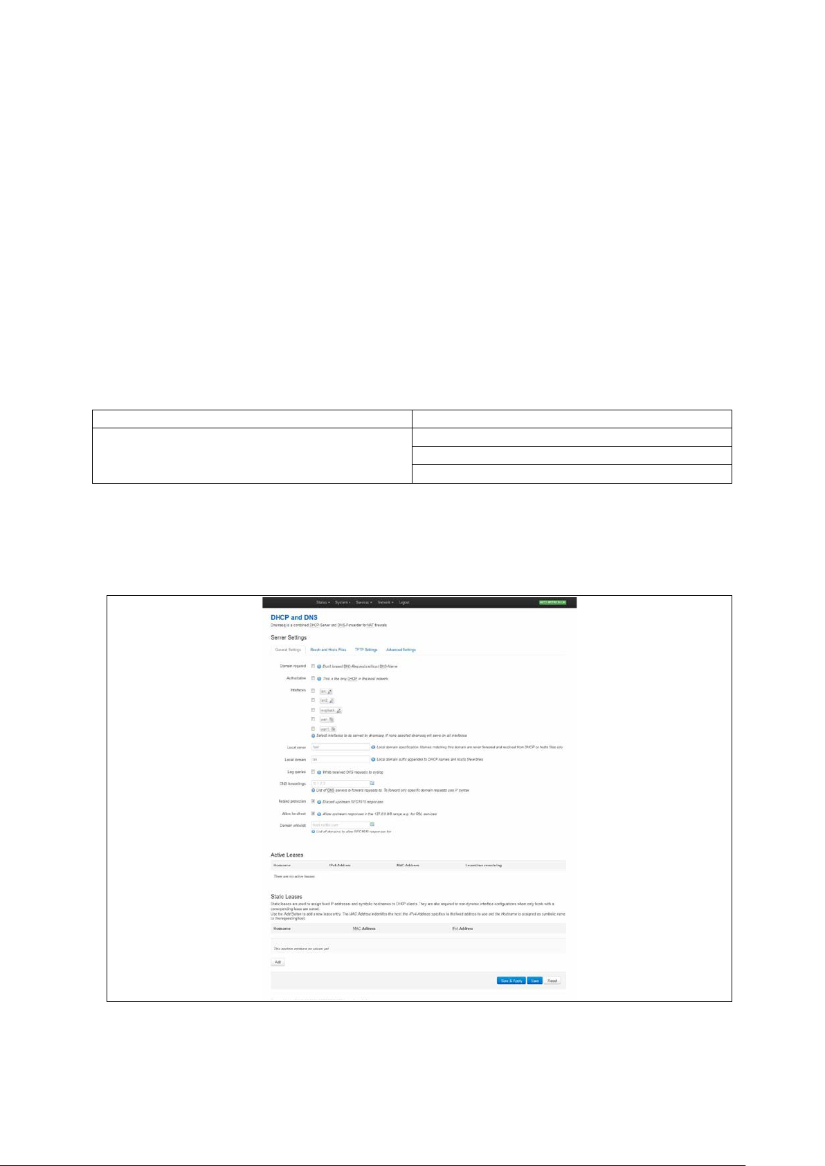
_______________________________________________________________________________________________________
Package
Sections
dnsmasq
dhcp
host
14: DHCP server and DNS configuration (Dnsmasq)
14 DHCP server and DNS configuration (Dnsmasq)
Dynamic Host Configuration Protocol (DHCP) server is responsible for assigning IP
addresses to hosts. IP addresses can be given out on different interfaces and different
subnets. You can manual ly configure lease time as well as setting static IP to host
mappings.
Domain Name Server (DNS) is responsible for resolution of IP addresses to domain
names on the internet.
Dnsmasq is the application which controls DHCP and DNS services. Dnsmasq has two
sections; one to specify general DHCP and DNS settings and one or more DHCP pools to
define DHCP operation on the desired network interface.
14.1 Configuration package use d
dhcp
14.2 Configuring DH CP and DNS using the web interface
In the top menu, select Network -> DHCP and DNS. The DHCP and DNS page
appears. There are three sections: Server Settings, Active Leases, and Static Leases.
Figure 46: The DHCP and DNS page
_______________________________________________________________________________________________________
© Virtual Access 2016
GW2020 Series User Manual
Issue: 1.4 Page 96 of 309
Page 97

_______________________________________________________________________________________________________
Web Field/UCI/Package Option
Description
1
Enabled.
0
Disabled.
1
Enabled.
0
Disabled.
Lan
Serve only on LAN interface
Range
/lan/
Range
lan Range
0
Disabled.
1
Enabled.
No DNS server configured.
Range
Opt: rebind_protection
0
Disabled.
1
Enabled.
0
Disabled.
1
Enabled.
No list configured.
Range
14.2.1 Dnsmasq: general settings
14: DHCP server and DNS configuration (Dnsmasq)
Web: Domain required
UCI: dhcp.@dnsmasq[0].domainneeded
Opt: domainneeded
Web: Authoritative
UCI: dhcp.@dnsmasq[0]. authorita tiv e
Opt: authoritative
Web: Interfaces
UCI: dhcp.@dnsmasq[0].interf a c e
Opt: list interface
Web: Local Server
UCI: dhcp.@dnsmasq[0].local
Opt: local
Web: Local Domain
UCI: dhcp.@dnsmasq[0].domain
Opt: domain
Web: Log Queries
UCI: dhcp.@dnsmasq[0].logqueries
Opt: logqueries
Web: DNS Forwardings
UCI: dhcp.@dnsmasq[0].server
Opt: list server
Defines whether to forward DNS requests without a DNS name.
Dnsmasq will never forward queries for plain nam e s , without
dots or domain parts, to upstream nameservers. If the name is
not known from /etc/hosts or DHCP then a "not found" answer
is returned.
Forces authoritative mode, this speeds up DHCP leasing . Used
if this is the only server in the network.
Defines the list of interfaces to be served by dnsmasq. If you
do not select a specific interface, dnsmas q will s erve on all
interfaces. Configured interfa ces are shown v i a the web GUI.
Specifies the local domain. Names matching this dom ain are
never forwarded and are resolved from DHCP or host files only.
Specifies local domain suffix appe nde d to DHCP name s and
hosts file entries.
Writes received DNS requests to syslo g.
List of DNS server to forward requests to. To forward specific
domain requests only, use // syntax. When using UCI, e nter
multiple servers with a space between them.
Web: Rebind Protection
UCI:
Enables DNS rebind attack protection by dis c ard ing up s tre am
RFC1918 responses.
dhcp.@dnsmasq[0].rebind_protection
Web: Allow Localhost
UCI: dhcp.@dnsmasq[0].reb ind_ localhost
Opt: rebind_localhost
Web: Domain Whitelist
UCI: dhcp.@dnsmasq[0].rebind_domain
Opt: list rebind_domain
Defines whether to allow upstream responses in the
127.0.0.0/8 range. This is required for DNS based blacklist
services. Only takes effect if rebind protec tio n is enabled.
Defines the list of domains to allow RFC1918 responses to. Only
takes effect if rebind protection is enab led. W he n using UCI
multiple servers should be entered with a space betwee n them.
Table 32: Information table for general server settings
_______________________________________________________________________________________________________
© Virtual Access 2016
GW2020 Series User Manual
Issue: 1.4 Page 97 of 309
Page 98

_______________________________________________________________________________________________________
Web Field/UCI/Package O ptio n
Description
Opt: readethers
1
Enabled.
0
Disabled.
es
Range
0
Use local DNS file.
1
Ignore local DNS file.
Opt: resolvfile
0
Use local hosts file.
1
Ignore local hosts file.
Opt: list addnhosts
14.2.2 Dnsmasq: resolv and host files
Figure 47: The resolv and host files section
14: DHCP server and DNS configuration (Dnsmasq)
Web: Use /etc/ethers
UCI: dhcp.@dnsmasq[0].readethe rs
Web: Leasefile
UCI: dhcp.@dnsmasq[0].leasefile
Opt: leasefile
Web: Ignore resolve file
UCI: dhcp.@dnsmasq[0].noreso l v
Opt: noresolv
Web: Resolve file
UCI: dhcp.@dnsmasq[0].resolvfile
Web: Ignore Hosts files
UCI: dhcp.@dnsmasq[0].nohosts
Opt: nohosts
Web: Additional Hosts files
UCI: dhcp.@dnsmasq[0].addnhosts
Table 33: Information table for resolv and host files section
Defines whether static lease entries are read from /etc/ethers.
Defines the file where given DHCP leases will be stored. The
DHCP lease file allows leases to be picked up again if dns masq is
restarted.
/tmp/dhcp.leas
Store DHCP leases in this file.
Defines whether to use the local DNS file for resolving DNS.
Defines the local DNS file. Default is /tmp/reso lv .co nf.auto
Defines whether to use local host’s files for reso lving DNS .
Defines local host’s files. When using UCI multiple servers should
be entered with a space between them.
_______________________________________________________________________________________________________
© Virtual Access 2016
GW2020 Series User Manual
Issue: 1.4 Page 98 of 309
Page 99

_______________________________________________________________________________________________________
Web Field/UCI/Package O ptio n
Description
0
Disabled.
1
Enabled.
Opt: tftp_root
Opt: dhcp_boot
14.2.3 Dnsmasq: TFTP settings
Figure 48: The TFTP settings section
14: DHCP server and DNS configuration (Dnsmasq)
Web: Enable TFTP Server
UCI: dhcp.@dnsmasq[0].enable_tftp
Opt: enable_tftp
Web: Enable TFTP Server
UCI: dhcp.@dnsmasq[0].tftp_r oo t
Web: Enable TFTP Server
UCI: dhcp.@dnsmasq[0].dhcp_bo ot
Table 34: Information table for TFTP settings
Enables the TFTP server.
Defines root directory for file served by TFTP.
Defines the filename of the boot image advertised to clients . This
specifies BOOTP options, in most cases just the file nam e .
_______________________________________________________________________________________________________
© Virtual Access 2016
GW2020 Series User Manual
Issue: 1.4 Page 99 of 309
Page 100

_______________________________________________________________________________________________________
Web Field/UCI/Package O ptio n
Description
1
Enabled.
0
Disabled.
1
Enabled.
0
Disabled.
1
Enabled.
0
Disabled.
14.2.4 Dnsmasq: advanced settings
14: DHCP server and DNS configuration (Dnsmasq)
Figure 49: The advanced settings page
Web: Filter private
UCI: dhcp.@dnsmasq[0].
Opt: boguspriv
Web: Filter useless
UCI: dhcp.@dnsmasq[0].filterwin2k
Opt: filterwin2k
Web: Localise queries
UCI: dhcp.@dnsmasq[0].localise_queries
Opt: localise_queries
_______________________________________________________________________________________________________
© Virtual Access 2016
GW2020 Series User Manual
Issue: 1.4 Page 100 of 309
Enables disallow option for forwar d ing reve r se look up s for local
networks. This rejects reverse look up s to priv a te IP ra nges where
no corresponding entry exists in /etc/hosts .
Enables disallow option for forwar d ing requests that cannot be
answered by public name servers. Normally enabled fo r dia l on
demand interfaces.
Defines whether to uses IP address to match the incoming
interface if multiple addresse s are ass igne d to a host name in
/etc/hosts.
 Loading...