

Page 1

GW2020 Series User Manual
Issue:
2.3
Date:
08 May 2015
Page 2

Table of Contents
_______________________________________________________________________________________________________
1 Introduction ............................................................................................... 10
1.1 Document scope ..................................................................................... 10
2 GW2020 Series hardware ........................................................................... 11
2.1 Hardware specification ............................................................................. 11
2.1.1 GW2020 series rou t e r m od el variants .................................................. 11
2.2 Hardware features .................................................................................. 11
2.3 Serial ports ............................................................................................ 11
2.3.1 Serial ports on the GW2020 series ...................................................... 12
2.3.1.1 RS232 pinout for the GW2020 .................................................................................. 12
2.3.1.2 RS485 pinout for the GW2020 .................................................................................. 12
2.3.2 Serial ports on the GW2024P .............................................................. 12
2.3.2.1 RS232 pinout for the GW2024P ................................................................................ 13
2.3.2.2 RS485 pinout for the GW2024P ................................................................................ 13
2.3.3 Serial ports on the GW2028 series ...................................................... 13
2.3.3.1 RS232 pin-out for the GW2028 ................................................................................. 13
2.3.3.2 RS485 pin-out for the GW2028 ................................................................................. 14
2.4 GSM technology ...................................................................................... 14
2.5 Power supply .......................................................................................... 14
2.5.1 GW2020 series ................................................................................. 14
2.5.2 GW2024P series ............................................................................... 14
2.5.3 GW2028 series ................................................................................. 14
2.6 Router dimensions .................................................................................. 15
2.7 Compliance ............................................................................................ 15
2.8 Operating temperature range ................................................................... 15
2.9 Antenna ................................................................................................. 16
2.10 Components ........................................................................................... 16
2.10.1 GW2020 Series components ............................................................... 16
2.10.2 GW2024P components ....................................................................... 17
2.10.3 GW2028 components ........................................................................ 17
2.11 Inserting the SIM cards ........................................................................... 17
2.12 Connecting the SIM lock .......................................................................... 18
2.13 Connecting cables ................................................................................... 18
2.14 Connecting the antenna ........................................................................... 18
2.15 Powering up the GW2020 ......................................................................... 18
2.16 Powering up the GW2024P ....................................................................... 18
2.17 Reset button .......................................................................................... 19
3 GW2020 Se r ies LED beha viour .................................................................... 20
3.1 Main LED behaviour................................................................................. 20
3.2 Ethernet port LED behaviour .................................................................... 21
_______________________________________________________________________________________________________
© Virtual Access 2015
GW2020 Series User Manual
Issue: 2.3 Page 2 of 264
Page 3

Table of Contents
_______________________________________________________________________________________________________
4 GW2024P Series LED behaviour.................................................................. 22
5 GW2028 Series LED behaviour .................................................................... 23
5.1 Main LED behaviour................................................................................. 23
5.2 Ethernet port LED behaviour .................................................................... 24
6 Factory configuration extraction from SIM card ......................................... 25
7 Accessing the router ................................................................................... 26
7.1 Over Ethernet ......................................................................................... 26
7.2 Over a 3G or 4G interface ........................................................................ 26
8 Upgrading router firmware ......................................................................... 27
8.1 Upgrading firmware using the web interface ............................................... 27
8.2 Upgrading firmware using CLI .................................................................. 29
9 File system ................................................................................................. 30
9.1 Configurations ........................................................................................ 30
9.1.1 High le vel configuration commands ..................................................... 30
9.1.2 Configuration file syntax .................................................................... 31
9.1.3 Command line utility ......................................................................... 32
9.1.3.1 Command line utility examples................................................................................. 34
9.1.4 Configuration copying and deleting ..................................................... 35
9.1.5 Image files ....................................................................................... 35
9.1.6 Viewing files ..................................................................................... 35
9.1.7 Copying files .................................................................................... 36
9.1.8 Editing files ...................................................................................... 37
9.1.9 Processes and jobs ............................................................................ 37
9.1.10 System informa tion ........................................................................... 37
10 Command Line Interface ............................................................................ 39
10.1 Basics .................................................................................................... 39
10.2 Unified Configuration Interface (UCI) ......................................................... 41
10.3 Configuration files ................................................................................... 45
10.4 Configuration file syntax .......................................................................... 45
10.5 Examples ............................................................................................... 46
10.5.1 Export an entire configuration ............................................................ 47
10.5.2 Display just the value of an option ...................................................... 47
11 Management configuration settings ........................................................... 48
11.1 Autoload - boot up activation .................................................................... 48
11.2 Httpclient - Activator configuration ............................................................ 50
11.3 System settings ...................................................................................... 53
11.3.1 Configuring a router’s host name ........................................................ 53
11.4 User management ................................................................................... 56
11.4.1 Configuration file: conf ig user ............................................................. 56
11.4.2 UCI export and UCI show commands ................................................... 58
_______________________________________________________________________________________________________
© Virtual Access 2015
GW2020 Series User Manual
Issue: 2.3 Page 3 of 264
Page 4

Table of Contents
_______________________________________________________________________________________________________
11.5 Interfaces configuration ........................................................................... 59
11.5.1 Interfaces ........................................................................................ 59
11.5.2 Options valid for all protocol types ...................................................... 60
11.5.3 Protocol "static" ................................................................................ 61
11.5.4 Protocol "dhcp" ................................................................................. 61
11.5.5 Protocol "3g" (PPP over EV-DO, CDMA, UMTS or GRPS) ......................... 61
11.5.6 Protocol "l2tp" (layer 2 tunneling protocol) ........................................... 62
11.5.7 Aliases ............................................................................................. 62
12 DHCP server and DNS configuration ........................................................... 65
12.1 Common options section .......................................................................... 65
12.2 DHCP pools ............................................................................................ 69
12.3 Static leases ........................................................................................... 71
13 VLAN configu r at ion ..................................................................................... 72
13.1 VLAN web interface ................................................................................. 72
13.2 VLAN definition ....................................................................................... 72
13.3 Port description ...................................................................................... 73
13.4 VLANs UCI interface ................................................................................ 74
13.4.1 config port ....................................................................................... 76
13.4.2 config vlan ....................................................................................... 76
13.4.3 Config nat vlan ................................................................................. 76
14 Static routes configuration ......................................................................... 77
14.1 IPv4 rou t es ............................................................................................ 77
14.2 IPv6 routes ............................................................................................ 78
15 BGP (Border Gateway Protocol).................................................................. 80
15.1 Configuring the BGP web interface ............................................................ 80
15.2 Optionally configure BGP route map .......................................................... 81
15.3 Configure BGP neighbours ........................................................................ 82
15.4 Routes statistics ..................................................................................... 82
15.5 BGP UCI interface ................................................................................... 83
16 Configuring WiFi ......................................................................................... 86
16.1 Configuring WiFi through the web interface ................................................ 86
16.2 Configuring WiFi in AP mode on an existing Ethernet interfa ce ...................... 86
16.3 Config uring W iFi in AP mode on a new interface .......................................... 90
16.4 Config uring W iFi in client mode ................................................................. 95
16.5 Config uring W iFi via UCI .......................................................................... 99
16.5.1 Configuring Wi-Fi in AP mode on an existing Ethernet interface .............. 99
16.5.2 Configuring WiFI on a new interface .................................................. 101
16.6 Config uring W iFi in client mode ............................................................... 103
17 Configuring a 3G/4G connection ............................................................... 105
18 Configuring SMS ....................................................................................... 108
_______________________________________________________________________________________________________
© Virtual Access 2015
GW2020 Series User Manual
Issue: 2.3 Page 4 of 264
Page 5

Table of Contents
_______________________________________________________________________________________________________
18.1 Monitoring SMS .................................................................................... 109
18.2 Outgoing messages ............................................................................... 109
19 Configuring Multi-WAN ............................................................................. 110
19.1 Multi-WAN web interface ........................................................................ 110
19.2 Multi-WAN UCI interface ........................................................................ 113
20 Automatic operator selection .................................................................... 116
20.1 Introduction to automatic operator selection ............................................ 116
20.2 Configuring automatic operator selection ................................................. 116
20.3 Configuring automatic operator selection via the web interface ................... 116
20.3.1 PMP + roaming: pre-empt enabled .................................................... 116
20.3.1.1 Creating primary predefined interface ............................................................... 117
20.3.1.2 Setting multi-WAN options for primary predefined interface ............................ 119
20.3.1.3 Setting options for automatically created interfaces ......................................... 121
20.3.2 PMP + roaming: pre-empt disabled ................................................... 126
20.3.3 Roaming: no PMP defined ................................................................ 127
20.3.4 Disable roaming .............................................................................. 128
21 Configuring IPSec ..................................................................................... 129
21.1 Common settings .................................................................................. 129
21.2 Connection settings ............................................................................... 130
21.3 Shunt connection .................................................................................. 134
21.4 Secret settin g s ..................................................................................... 134
22 Configuring firewall .................................................................................. 137
22.1 Defaults section .................................................................................... 137
22.2 Zones section ....................................................................................... 137
22.3 Forwarding sections .............................................................................. 138
22.4 Redirects ............................................................................................. 139
22.5 Rules ................................................................................................... 140
22.6 Includes ............................................................................................... 141
22.7 IPv6 notes ........................................................................................... 141
22.8 Implications of DROP vs. REJECT ............................................................ 142
22.9 Note on connection tra cking ................................................................... 143
22.10 Firewall examples .............................................................................. 143
22.10.1 Opening ports ............................................................................. 143
22.10.2 Forwarding ports (destination NAT/DNAT) ....................................... 143
22.10.3 Source NAT (SNAT) ...................................................................... 144
22.10.4 True destination port forwarding .................................................... 145
22.10.5 Block access to a specific host ....................................................... 145
22.10.6 Block access to the internet using MAC ........................................... 145
22.10.7 Block access to the internet for specific IP on certain times ............... 145
22.10.8 Restricted forwarding rule ............................................................. 146
_______________________________________________________________________________________________________
© Virtual Access 2015
GW2020 Series User Manual
Issue: 2.3 Page 5 of 264
Page 6

Table of Contents
_______________________________________________________________________________________________________
22.10.9 Transparent proxy rule (same host) ............................................... 146
22.10.10 Transparent proxy rule (external) .................................................. 146
22.10.11 Simple DMZ rule .......................................................................... 147
22.10.12 IPSec passthrough ....................................................................... 147
22.10.13 Manual ipta bles rules .................................................................... 148
22.11 Firewall management ......................................................................... 148
22.12 Debug generated rule set .................................................................... 149
23 Configuring SNMP ..................................................................................... 150
23.1 agent .................................................................................................. 150
23.2 system ................................................................................................ 151
23.3 com2sec .............................................................................................. 151
23.4 access ................................................................................................. 154
23.5 SNMP traps .......................................................................................... 155
24 Configuring HTTP server ........................................................................... 156
24.1 Server settings ..................................................................................... 156
24.2 HTTPS certificate settings and creation .................................................... 158
24.3 Basic authentication (httpd.conf) ............................................................ 159
24.4 Securing uHTTPd .................................................................................. 160
24.5 SSH server configuration ....................................................................... 160
25 Virtual Router Redundancy Protocol (VRRP) ............................................ 161
25.1 Software versi on s ................................................................................. 161
25.2 VRRP web interface ............................................................................... 162
25.3 Configuring VRRP using UCI ................................................................... 165
26 Multicasting using PIM and IGMP interfaces ............................................. 167
26.1 Configuring PIM and IGMP via the web interface ....................................... 167
26.2 PIM and IGMP UCI interface ................................................................... 169
27 Dynamic Multipoint Virtual Private Network (DMVPN) ............................. 171
27.1 The advantage of using DM V PN .............................................................. 171
27.2 DMVPN scenari os .................................................................................. 171
27.3 Configuring DMVPN via the web interface ................................................. 173
27.3.1 Configuring IPSec for DMVPN ........................................................... 174
27.4 DMVPN hub settings .............................................................................. 180
27.5 UCI interface ........................................................................................ 181
27.5.1 IPSec configuration using CLI ........................................................... 181
27.6 Configuring DMVPN using CLI ................................................................. 183
28 Terminal Server ........................................................................................ 185
28.1 Introduction ......................................................................................... 185
28.2 Terminal Server interfaces ..................................................................... 185
28.3 Configuring Terminal Server ................................................................... 185
28.3.1 Configuring Terminal Server using the web interface ........................... 185
_______________________________________________________________________________________________________
© Virtual Access 2015
GW2020 Series User Manual
Issue: 2.3 Page 6 of 264
Page 7

Table of Contents
_______________________________________________________________________________________________________
28.3.1.1 Main settings ....................................................................................................... 185
28.3.1.2 Port settings ........................................................................................................ 186
28.3.1.3 Port settings: general section ............................................................................. 186
28.3.1.4 Port settings: serial section ................................................................................. 188
28.3.1.5 Port settings: network section ............................................................................ 190
28.4 Configuring Terminal Server using UCI .................................................... 192
28.5 Terminal Server operation ...................................................................... 202
28.5.1 General ......................................................................................... 202
28.5.2 Starting Terminal Server .................................................................. 202
28.5.3 Checking the status of Terminal Server ............................................. 202
28.5.4 Stopping Terminal Server ................................................................ 203
29 GRE interfaces .......................................................................................... 204
29.1 GRE web interface ................................................................................. 204
29.2 GRE UCI interface ................................................................................. 206
30 Configuring a COSEM HDLC Bridge ............................................................ 208
30.1 COSEM HDLC web interface .................................................................... 208
30.2 Checking the status of COSEM HDLC Bridge ............................................. 209
31 Event system ............................................................................................ 210
31.1 Implementation of the event system ....................................................... 210
31.2 Supported events .................................................................................. 210
31.3 Supported targets ................................................................................. 210
31.4 Supported connection testers ................................................................. 211
31.5 Configuring the event system via the web interface ................................... 211
31.6 Configuring the event system via UCI ...................................................... 211
31.6.1 Main section ................................................................................... 211
31.6.2 Forwardings ................................................................................... 212
31.6.3 Connection testers .......................................................................... 212
31.6.3.1 Ping connection tester ........................................................................................ 213
31.6.3.2 Link connection tester ......................................................................................... 213
31.6.4 Supported targets ........................................................................... 214
31.6.4.1 Syslog target ........................................................................................................ 214
31.6.4.2 Email target ......................................................................................................... 215
31.6.4.3 SNMP target ........................................................................................................ 216
31.6.4.4 Exec target .......................................................................................................... 216
31.6.5 Example and export ........................................................................ 217
32 Configuring SLA reporting on Monitor ....................................................... 223
32.1 Introduction ......................................................................................... 223
32.2 Configuring SLA reporting ...................................................................... 223
_______________________________________________________________________________________________________
© Virtual Access 2015
GW2020 Series User Manual
Issue: 2.3 Page 7 of 264
Page 8

Table of Contents
_______________________________________________________________________________________________________
32.2.1 Configuring a content template ......................................................... 223
32.3 Adding an SLA report ............................................................................ 226
32.4 Viewing an SLA report ........................................................................... 228
32.5 Viewing automated SLA reports .............................................................. 229
32.6 Configuring router upload protocol .......................................................... 230
33 Configuring SLA for a router ..................................................................... 231
33.1 Configuring SLA for a router via the web interface ..................................... 231
33.2 Configuring SLA for a router via UCI interface ........................................... 233
33.3 SLA statistics ........................................................................................ 234
34 Diagnostics ............................................................................................... 236
34.1 ADSL diagnostics .................................................................................. 236
34.1.1 ADSL PPPoA connections .................................................................. 236
34.1.2 ADSL PPPoEoA connections .............................................................. 236
34.1.3 ADSL bridge connections ................................................................. 237
34.2 ALL diagnostics ..................................................................................... 238
34.3 Automatic operator selection diagnostics via the web interface ................... 239
34.3.1 Checking the status of the Multi-WAN package ................................... 239
34.4 Automatic operator selection diagnostics via UCI ...................................... 240
34.5 CESoPSN diagnostics ............................................................................. 242
34.5.1 cesop show config ........................................................................... 242
34.5.2 cesop show status ........................................................................... 244
34.5.3 cesop show stats ............................................................................ 244
34.5.4 cesop clea r st a ts ............................................................................. 245
34.6 DMVPN diagnostics ................................................................................ 246
34.7 File system diagnostics .......................................................................... 248
34.8 Firewall diagnostics ............................................................................... 249
34.8.1 IP tables ........................................................................................ 252
34.8.2 Debug ........................................................................................... 252
34.9 GPS diagnostic commands ..................................................................... 253
34.10 Interfaces diagnostics ......................................................................... 253
34.10.1 Interfaces status .......................................................................... 253
34.10.2 Route status................................................................................ 254
34.10.3 Mobile status ............................................................................... 254
34.10.4 ADSL status ................................................................................ 255
34.11 ISDN pseudowire diagnostics ............................................................... 256
34.11.1 Packages .................................................................................... 256
34.11.2 Asterisk CLI diagnostics ................................................................ 257
34.11.3 ISDN LED status .......................................................................... 258
34.12 IPSec diagnostics ............................................................................... 258
34.13 Multi-WAN diagnostics ........................................................................ 259
_______________________________________________________________________________________________________
© Virtual Access 2015
GW2020 Series User Manual
Issue: 2.3 Page 8 of 264
Page 9

Table of Contents
_______________________________________________________________________________________________________
34.14 PAD diagnostics ................................................................................. 260
34.14.1 Showing Log ............................................................................... 260
34.14.2 Debugging guidelines ................................................................... 261
34.15 Terminal Server diagnostics ................................................................ 262
34.16 VRRP diagnostics ............................................................................... 263
34.16.1 VRRP diagnostics web interface ..................................................... 263
34.16.2 VRRP diagnostics using the command line interface ......................... 263
34.17 Diagnostics for WiFi AP mode .............................................................. 264
34.18 Diagnostics for WiFi client mod e .......................................................... 264
_______________________________________________________________________________________________________
© Virtual Access 2015
GW2020 Series User Manual
Issue: 2.3 Page 9 of 264
Page 10

1: Introduction
_______________________________________________________________________________________________________
1 Introduction
This user manual describes the features and how to configure a Virtual Access
GW2020 Series router.
The Virtual Access GW2020 Series router is a versatile 3G/4G LTE/CDMA450
wireless router suitable for a variety of business and industrial deployments. The
compact and rugged structure makes it a suitable product for deployments in
M2M applications such as CCTV, ATM, telemetry, SCADA, retail (POS), digital
signage, and intelligent traffi c systems. The product line supports the following
radio access technologies: HSPA+, HSPA, UMTS, EDGE, CDMA450, GPRS and
GSM.
3G is the third generation of mobile phone standards and technology. It is based
on the International Telecommunication Union (ITU) family of standards under
the International Mobile Telecommunications programme, IMT-2000.
4G is a mobile communications standard intended to replace 3G, allowing
wireless internet access at a much higher speed.
3G and 4G technologies enable network operators to offer users a wider range of
more advanced services, while achieving greater network capacity through
improved spectral effiecieny. Services include wide-area wireless voice
telephony, video calls, and broadband wireless data, all in a mobile environment.
1.1 Document scope
This document covers the following models in the GW2020 Series.
GW2021:
Single Ethernet and 3G, 4G/LTE
GW2022: Dual Ethernet and 3G, 4G/LTE
GW2023: Dual Ethernet, 3G, 4G/LTE an d dual RS232
GW2024: Dual Ethernet, 3G, 4G/LTE, s ingle RS232 and single RS485
GW2024P:
Dual Ethernet, 3G, 4G/LTE, s ingle RS232 and single RS485, plastic case
GW2027: Dual Ethernet, 3G, 4G/LTE, CDMA450, single RS232 and single R S485, Digital I/O
Note: the second input is either RS232 or RS485 an d is s pec if ied a t time of
ordering and fixed in manuf a c tu r ing.
GW2028: Quad Ethernet, 3G, 4G/LTE, CDMA450,single RS232 and single RS485, Digital I/O
Note: the second input is either RS232 or RS485 an d is s pec if ied a t time of
ordering and fixed in manuf a c tu r ing.
Throughout this document:
• We use t h e host name ‘VA_router’.
• We ref er to the GW2020 Series for configuration and UCI instructions.
_______________________________________________________________________________________________________
© Virtual Access 2015
GW2020 Series User Manual
Issue: 2.3 Page 10 of 264
Page 11

2: GW2020 Series hardware
_______________________________________________________________________________________________________
2 GW2020 Series hardware
2.1 Hardware specification
2.1.1 GW2020 series router model variants
GW2021: Single Ethernet and 3G, 4G/LTE
GW2022:
Dual Ethernet and 3G, 4G/LTE
GW2023: Dual Ethernet, 3G, 4G/LTE an d dual RS232
GW2024: Dual Ethernet, 3G, 4G/LTE, s ingle RS232 and single RS485
GW2024P: Dual Ethernet, 3G, 4G/LTE, sin gle R S 232 a nd single RS485, plastic case
GW2027: Dual Ethernet, 3G, 4G/LTE, CDMA450, single RS232 and single R S485, Digital I/O
Note: the second input is either R S232 or RS485 and is specified at time of
ordering and fixed in manuf a c turing.
GW2028: Quad Ethernet, 3G, 4G/LTE, CDMA450,single RS232 and single R S485, Digital I/O
Note: the second input is either R S232 or RS485 and is specified at time of
ordering and fixed in manufacturing.
2.2 Hardware features
• Dual SIM sockets
• Dual antenna SMA connectors
• One or two 10/100 Mbps Ethernet ports.
• Optional 1 or 2 RS232 ports
• Optional 4Kv isolation ports
• Optional RS485 port
• SIM c ov er
• GW2024P only: optional 2.2 seconds last GASP hold up time
2.3 Serial ports
The asynchronous serial ports are named:
• Port 0: ‘/dev/ttySC0’
• Port 1: ‘/dev/ttySC1’
Each serial port has a number of configurable settings, such as baud rate, word
size, parity, flow control mode, etc.
_______________________________________________________________________________________________________
© Virtual Access 2015
GW2020 Series User Manual
Issue: 2.3 Page 11 of 264
Page 12

2: GW2020 Series hardware
_______________________________________________________________________________________________________
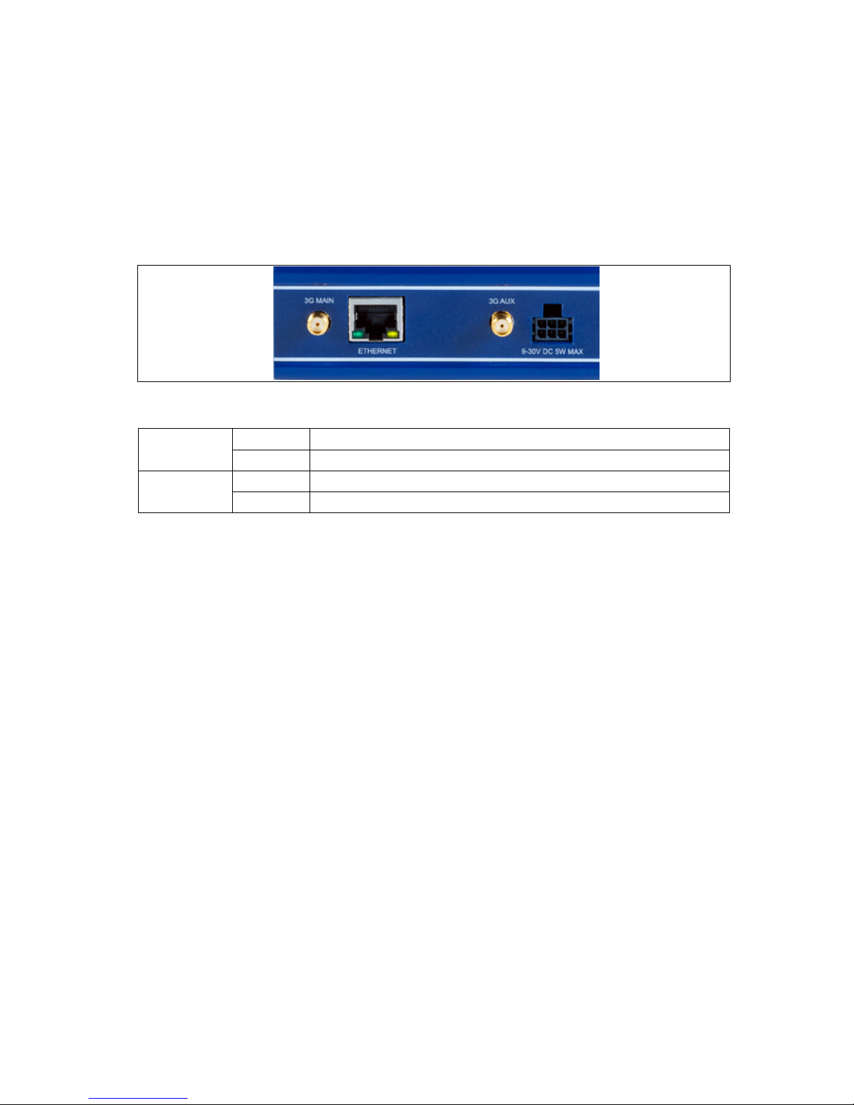
2.3.1 Serial ports on the GW2020 series
Figure 1: Serial ports on the GW2020
2.3.1.1 RS232 pinou t f or th e GW 2 020
Pin Name Direction
1 RTS Out
2 DTR Out
3 TX Data Out
4 GND 5 GND -
6
RX Data
In 7 DSR
In
8
CTS
In
2.3.1.2 RS485 pinout for the GW2020
Half Duplex Mode Full Duplex Mode
Pin Name Direction
(From GW2020 Series)
Name Direction
(From GW2020 Series)
1 - -
Rx+
In
2 - - Rx- In
3 Tx/Rx+ In/Out Tx+ Out
4 GND - GND 5 GND - GND 6 Tx/Rx In/Out Tx- Out
7 - - - 8 - - - -
2.3.2 Serial ports on the GW2024P
Figure 2: Serial ports on the GW2024P
_______________________________________________________________________________________________________
© Virtual Access 2015
GW2020 Series User Manual
Issue: 2.3 Page 12 of 264
Page 13

2: GW2020 Series hardware
_______________________________________________________________________________________________________
2.3.2.1 RS232 pinou t f or th e GW 2 024P
Pin Name Direction
1 RTS Out
2 DTR Out
3 TX Data Out
4 GND -
5
GND
- 6 RX Data
In
7 DSR In
8 CTS In
2.3.2.2 RS485 pinou t f or th e GW 2 024P
Half Duplex Mode
Pin Name Direction
(From GW2024P router)
1
2 GND 3 Tx/Rx+ In/Out
4 Tx/Rx+ In/Out
5 Tx/Rx- In/Out
6 Tx/Rx- In/Out
7
8
2.3.3 Serial ports on the GW2028 series
Figure 3: Serial ports on the GW2028
2.3.3.1 RS232 pin-out for the GW2028
Pin
Name
Direction
1
RTS
Out
2 DTR Out
3 TX Data Out
4 GND 5 GND 6 RX Data In
7 DSR In
8 CTS In
_______________________________________________________________________________________________________
© Virtual Access 2015
GW2020 Series User Manual
Issue: 2.3 Page 13 of 264
Page 14

2: GW2020 Series hardware
_______________________________________________________________________________________________________
2.3.3.2 RS485 pin-out for the GW2028
Half Duplex Mode Full Duplex Mode
Pin Name Direction
(From GW2020 Series)
Name Direction
(From GW2020 Series)
1 - - Rx+ In
2 - - Rx- In
3 Tx/Rx+ In/Out Tx+ Out
4 GND - GND 5 GND - GND 6 Tx/Rx In/Out Tx- Out
7 - - - 8 - - - -
2.4 GSM technology
• HSPA+
• EDGE/GPRS
• Download up to 21 Mbps
• Upl oad up to 5.76 Mbps
• 2100/1900/900/850 MHz Bands
2.5 Power supply
2.5.1 GW2020 series
The GW2020 Series router has three power supply options:
• 100V-240V AC PSU (standard)
• 100V-240V AC PSU with extended temperature support -20°C to +70°C
• 10V-30V DC power lead
2.5.2 GW2024P series
The GW2024P is powered from a 24V AC input, and can be supplied with a 240 –
24V AC DIN mounted transformer. Any alternative power supply used should be
a limited power supply with a secondary circuit protection device, such as a PTC.
• DIN rail 240 – 24V AC transformer, -40°C to +70°C
2.5.3 GW2028 series
• DIN rail 100V-240V AC PSU -20°C to +70°C
_______________________________________________________________________________________________________
© Virtual Access 2015
GW2020 Series User Manual
Issue: 2.3 Page 14 of 264
Page 15

2: GW2020 Series hardware
_______________________________________________________________________________________________________
2.6 Router dimensions
GW2020 Series unit size: 100W 138D 34H mm
GW2020 Series unit weight: 500g
GW2024P Series unit size: 160W 75D 120H
GW2024P Series unit weigh t:
1200g
GW2028 Series unit size: 52W 116D 157H
GW2028 Series unit weight: 500g
2.7 Compliance
The GW2020 Series router is compliant and tested to the following standards:
Safety
EN60950-1: 2001
EMC EN55022:1998 Class B and EN 55024: 1998 Class B
Environmental ETSI 300 019-1-3 Sin usoidal Vibration and Shock ETSI 300 019-2-3 Random
Vibration.
The GW2024P Series router is compliant and tested to the following standards:
Safety EN60950
EMC EN55022 and EN55024 for more s pec if ic details please read the GW2024P
datasheet.
Environmental ETSI 300 019-1-3 Sinusoidal Vibration and Shock ETSI 300 019-2-3 R a ndom
Vibration.
The GW2028 Series router is compliant and tested to the following standards:
Safety EN60950
EMC EN55022 and EN55024 for more s pec if ic details please read the GW2028
datasheet.
Environmental ETSI 300 019-1-3 Sinusoidal Vibrati on and Shock ETSI 300 019-2-3 Ran dom
Vibration.
2.8 Operating tempe ratu re ran ge
The operating temperature range depends on the router’s type of power supply.
GW202X 0°C to 40°C Standard AC PSU
GW202X-ET
-20°C to 70°C
Extended temperature AC PSU
GW202X-DC -20°C to 70°C DC power cable
GW2024P -40°C to 70°C DIN Rail PSU
GW2028 -20°C to 70°C DIN Rail PSU
_______________________________________________________________________________________________________
© Virtual Access 2015
GW2020 Series User Manual
Issue: 2.3 Page 15 of 264
Page 16

2: GW2020 Series hardware
_______________________________________________________________________________________________________
2.9 Antenna
The GW2020 Series router has two SMA connectors for connection of two
antennas for antenna diversity. Antenna diversity helps improve the quality of a
wireless link by mitigating problems associated with multipath interference.
2.10 Components
To enable and configure connections on your router, it must be correctly
installed.
The GW2020 Series router contains an internal web server that you use for
configurations. Before you can access the internal web server and start the
configuration, ensure the components are correctly connected and that your PC
has the correct networking setup.
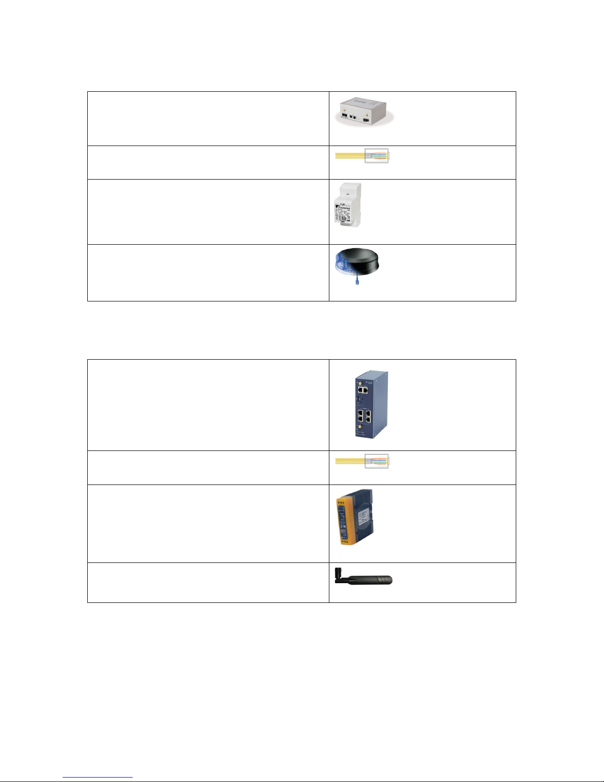
2.10.1 GW2020 Series components
The GW2020 Series router comes with the following components as standard:
1 x GW2020 Series router (models var y ) .
1 x Ethernet cable. RJ45 connec tor a t both ends.
1 x power supply unit.
1 x rubber right angle antenna.
Table 1: GW2020 Series router standard components
Optional components include:
1 x lockable SIM cover.
1 x extra antenna Virtual Access supplies a wide range of antennas. Please visit our
website: www.virtualaccess.com or contact Virtual Access for more
information.
Table 2:GW2020 Series router optional components
_______________________________________________________________________________________________________
© Virtual Access 2015
GW2020 Series User Manual
Issue: 2.3 Page 16 of 264
Page 17
2: GW2020 Series hardware
_______________________________________________________________________________________________________
2.10.2 GW2024P components
1 x GW2024P Series router
1 x Ethernet cable. RJ45 connec tor a t both ends
1 x AC transformer
1 x SmartDisc antenna
Table 3: GW2024P Series router components
2.10.3 GW2028 components
1 x GW2028 Series router
1 x Ethernet cable. RJ45 connec tor a t both ends.
1 x PSU
1 x antenna
Table 4: GW2028 Series router components
2.11 Inserting the SIM cards
1. Ensure the unit is powered off.
2. Hold the SIM 1 card with the chip side facing down and the cut corner front left.
3. Gently push the SIM card into SIM slot 1 until it clicks in.
_______________________________________________________________________________________________________
© Virtual Access 2015
GW2020 Series User Manual
Issue: 2.3 Page 17 of 264
Page 18

2: GW2020 Series hardware
_______________________________________________________________________________________________________
4. If using SIM 2 then hold the SIM with the cut corner front right
5. Gently push the SIM card into SIM slot 2 until it clicks in.
2.12 C o nnecting the SIM lock
Connect the SIM lock using the Allen key provided.
2.13 C o nnecting cables
Connect one end of the Ethernet cable into port A and the other end to your PC
or switch.
2.14 C o nnecting the antenna
If you are only connecting one antenna, screw the antenna into the MAIN SMA
connector.
If you are using two antennas, screw the main antenna into the MAIN SMA
connector and the secondary antenna into the AUX SMA connector.
2.15 Powering up the GW2020
Plug the power cable into an electrical socket suitable for the power supply.
The GW2020 takes approximately 2 minutes to boot up. During this time, the
power LED flashes.
Other LEDs display different diagnostic patterns during boot up.
Booting is complete when the power LED stops flashing and stays on steady.
2.16 Po w ering up the GW2024P
The GW2024P is supplied with an external DIN mount AC transformer, 230V AC
input and 24V AC output. Both the input and output connectors use Philips head
screws in a terminal block.
Slide the terminal block covers off using a small amount of pressure.
Wire the 230V AC input to the electrical supply in accordance with local
regulations.
Wire the 24V AC output to the supplied 2 pin terminal connector.
Replace the covers on the AC transformer terminal block.
Connect the 24V AC output to the GW2024P.
_______________________________________________________________________________________________________
© Virtual Access 2015
GW2020 Series User Manual
Issue: 2.3 Page 18 of 264
Page 19

2: GW2020 Series hardware
_______________________________________________________________________________________________________
2.17 Reset button
The reset button is used to request a system reset.
When you press the reset button all LEDs turn on simultaneously. The length of
time you hold the reset button will determine its behaviour.
Press Duration Behaviour
Less than 3 seconds Normal reset.
Between 3 and 5 seconds The router resets to factory configuration.
Between 20 seconds and 25 secon ds Recovery mode.
Over 25 seconds Normal reset
Table 5: GW2020 Series router reset behaviour
_______________________________________________________________________________________________________
© Virtual Access 2015
GW2020 Series User Manual
Issue: 2.3 Page 19 of 264
Page 20

3: GW2020 Series LED behaviour
_______________________________________________________________________________________________________
3 GW2020 Series LED behaviour
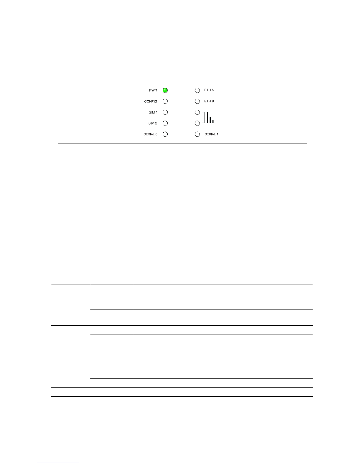
3.1 Main LED behaviour
The GW2020 Series rout er h as single colour LEDs for Power, Config, SIM1, SIM2
and signal strength. When the router is powered on, the LED is green.
Figure 4: Example of power and config LED activity : p ower and config are on
The possible LED states are:
• Off
• Flashing slowing
• Flashing quickly
• On
The following table describes the possible LED behaviour and meaning.
Booting
The GW2020 takes approximately 2 m inutes to boot up.
During this time, the power LED flashes.
Other LEDs display d ifferent diagnos tic patterns during boot
up.
Booting is complete when the power LED stops flashing and
stays on steady.
Power LED
On Power.
Off No power/boot loader does not exist.
Config LED
On Unit running a v a lid c onfiguration file.
Flashing slowly Unit running in recovery mode (5 Hz).
Flashing quickly Unit running in factory c onfiguration (2.5 Hz).
SIM LEDs
On
SIM selected and registered on the netw ork.
Off
Not selected or SIM not inserted.
Flashing SIM selected and not registered on the n etw or k.
Signal LEDs
None PPP not connected or signal strength <= -113dBm.
1 PPP connected and signal stren gth <= -89dBm.
2 PPP connected and signal stren gth between -89dBm and -
69dBm.
3 PPP connected and signal stren gth >-69dBm.
Table 6: LED behaviour and descriptions
_______________________________________________________________________________________________________
© Virtual Access 2015
GW2020 Series User Manual
Issue: 2.3 Page 20 of 264
Page 21
3: GW2020 Series LED behaviour
_______________________________________________________________________________________________________
Note: When PPP is not connected, none of the signal LEDs will light regardless
of signal strength.
3.2 Ethernet port LED behaviour
The Ethernet port has two LEDs: a LINK LED (green) and an ACT LED (amber).
When looking at the port, the LED on the left hand side is the LINK LED, and the
ACT LED is on the right hand side.
Figure 5: Ethernet LED activity
Link LED
(green)
Off No physical Ethernet link detected.
On Physical Ethernet link detected.
ACT LED
(amber)
Off No data is being transmitted/received over the link.
Flashing
Data is being transmitted/ rec eived over the link.
_______________________________________________________________________________________________________
© Virtual Access 2015
GW2020 Series User Manual
Issue: 2.3 Page 21 of 264
Page 22
4: GW2024P Series LED behaviour
_______________________________________________________________________________________________________
4 GW2024P Series LED behaviour
The GW2024P Series router has a single colour LED. When the router is powered
on, the LED is green.
Figure 6: LED activity
The possible LED states are:
• Off
• Flashing slowing
• Flashing quickly
• On
The following table describes the possible LED behaviours and meanings.
Booting
The GW2024P takes approximately 2 m inutes to boot up. D uring this time, the power
LED flashes.
Other LEDs display differe nt diagnostic pattern s during boot up.
Booting is complete when the power LED stops f lashing and stays on steady.
Power
On Power.
Off No power/boot loader does not exist.
Config
On
Unit running a v a lid c onfiguration file.
Flashing
slowly
Unit running in recover y mode (5 Hz).
Flashing
quickly
Unit running in factory configuration (2.5 Hz).
SIM
On SIM selected and already register ed on the network.
Off Not selected or SIM not ins e r te d.
Flashing SIM selected and in th e process of r egis tering on the network.
Signal*
None PPP not connected or signal strength <= -113dBm.
1 PPP connected and signal strength <= -89dBm.
2 PPP connected and signal strength between -89dBm and -69dBm.
3 PPP connected and signal strength >-69dBm
*Note: When PPP is not c onnected, none of the signal LEDs will light reg a rdless of signa l strength.
_______________________________________________________________________________________________________
© Virtual Access 2015
GW2020 Series User Manual
Issue: 2.3 Page 22 of 264
Page 23
5: GW2028 Series LED behaviour
_______________________________________________________________________________________________________
5 GW2028 Series LED behaviour
5.1 Main LED behaviour
The GW2028 Series rout er h as single colour LEDs for Power, Config, SIM1, SIM2
and signal strength. When the router is powered on, the LED is green.
Figure 7: Example of power and config LED activity: power and config are on
The possible LED states are:
• Off
• Flashing slowing
• Flashing quickly
• On
The following table describes the possible LED behaviour and meaning.
Booting
The GW2028 takes approximately 2 m inutes to boot up.
During this time, the power LED flashes.
Other LEDs display different diag nostic patterns during
boot up.
Booting is complete when the power LED stops flashing
and stays on steady.
_______________________________________________________________________________________________________
© Virtual Access 2015
GW2020 Series User Manual
Issue: 2.3 Page 23 of 264
Page 24

5: GW2028 Series LED behaviour
_______________________________________________________________________________________________________
Power LED
On Power
Off No power/boot loader does not exist
Config LED
On Unit running a v a lid c onfiguration file.
Flashing slowly Unit running in recovery mode (5 Hz).
Flashing quickly Unit runn ing in factory configu r a tion (2.5 Hz)
SIM LEDs
On SIM selected and registered on the network
Off Not s ele cted or SIM not inserted
Flashing SIM selected and not registered on the network
Signal LEDs
None PPP not connected or signal strength <= -113dBm
1
PPP connected and signal stren gth <= -89dBm.
2 PPP connected and signal strength between -89dBm and
-69dBm.
3 PPP connected and signal strength >-69dBm
Table 7: LED behaviour and descriptions
Note: When PPP is not connected, none of the signal LEDs will light regardless
of signal strength.
5.2 Ethernet port LED behaviour
The Ethernet port has two LEDs: a LINK LED (green) and an ACT LED (amber).
When looking at the port, the LED on the top is the LINK LED, and the ACT LED
is on the bottom.
Figure 8: Ethernet LED activity
Link LED
(green)
Off No physical Ethern et link detected
On Physical Ethernet link detected
ACT LED
(amber)
Off No data is being transmitted/received over the link
Flashing Data is being trans m itted/ received over the link
_______________________________________________________________________________________________________
© Virtual Access 2015
GW2020 Series User Manual
Issue: 2.3 Page 24 of 264
Page 25

6: Factory configuration extraction from SIM card
_______________________________________________________________________________________________________
6 Factory configuration extract ion from SIM c ar d
Virtual Access routers have a feature to update the factory configuration from a
SIM card. This allows you to change the factory configuration of a router when
installing the SIM.
1. Make sure the SIM card you are inserting has the required configuration written on it.
2. Ensure the router is powered off.
3. Hold the SIM 1 card with the chip side facing down and the cut corner front left.
4. Gently push the SIM card into SIM slot 1 until it clicks in.
5. Power up the router.
Depending on the model, the power LED and/or the configuration LED flash as
usual.
The SIM LED starts flashing. This indicates the application responsible for 3G and
configuration extraction management is running. It also means the update of the
configuration is happening.
When the update is finished, depending on the model, the power LED and/or the
configuration LED blink alternatively and very fast for 20 seconds.
_______________________________________________________________________________________________________
© Virtual Access 2015
GW2020 Series User Manual
Issue: 2.3 Page 25 of 264
Page 26

7: Accessing the router
_______________________________________________________________________________________________________
7 Accessing the router
Access the router using either Ethernet or the 3G/4G interface.
7.1 Over Ethernet
The CLI can also be accessed over Ethernet, by default using Secure Shell (SSH)
and optionally over Telnet
To access CLI over Ethernet start an SSH client and connect to the router’s
management IP address, on port 22: 192.168.100.1/24. Then enter the
default username and password.
Username: Root
Password: Admin
Figure 9: SSH CLI logon screen
7.2 Over a 3G or 4G interface
You can also access the CLI over the router’s 3G or 4G interface using Secure
Shell (SSH) and optionally over Telnet.
To access CLI start an SSH client and connect to the router’s 3G or 4G IP
interface on port 22: 192.168.100.1/24. Then enter the default username and
password.
Username: Root
Password: Admin
_______________________________________________________________________________________________________
© Virtual Access 2015
GW2020 Series User Manual
Issue: 2.3 Page 26 of 264
Page 27
8: Upgrading router firmware
_______________________________________________________________________________________________________
8 Upgrading router firmware
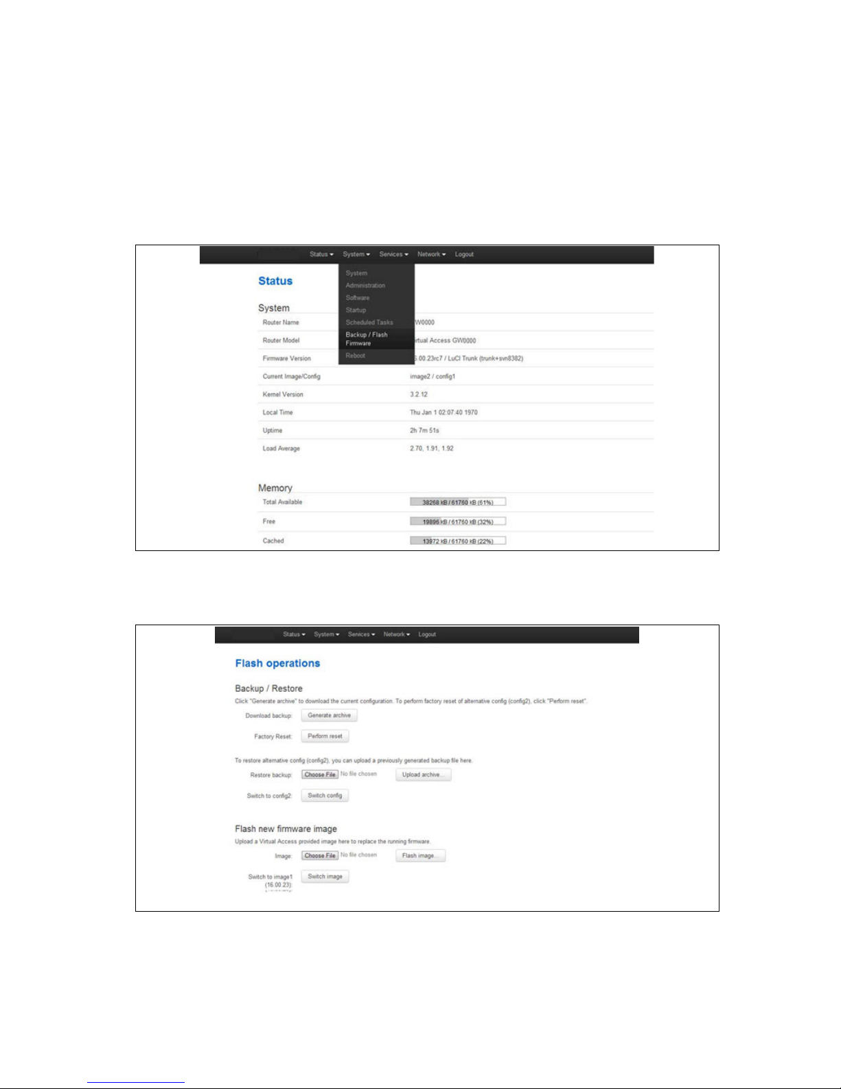
8.1 Upgrading fir mware using the web interface
Copy the new firmware issued by Virtual Access to a PC connected to the router.
In the top menu, selec t System tab > Backup/Flash Firmware.
Figure 10: The system menu
The Flash operations page appears.
Figure 11: The flash operations pag e
Under Flash new firmware image, click Choose File or Browse.
_______________________________________________________________________________________________________
© Virtual Access 2015
GW2020 Series User Manual
Issue: 2.3 Page 27 of 264
Page 28
8: Upgrading router firmware
_______________________________________________________________________________________________________
Note: the button will vary depending on the browser you are using.
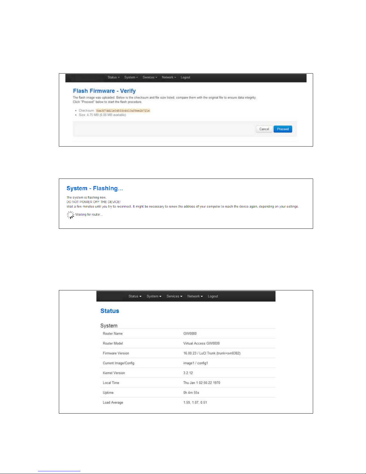
Select the appropriate image and then click Flash Image. The Flash Firmware –
Verify page appears.
Figure 12: The flash firmware - verify page
Click Proceed. The System – Flashing… page appears.
Figure 13: The system – flashing…page
When the ‘waiting for router’ icon disappears, the upgrade is complete, and the
login homepage appears.
To verify that the router has been upgraded successfully, click Status in the top
menu. The Firmware Version shows in the system list.
Figure 14: The status page
_______________________________________________________________________________________________________
© Virtual Access 2015
GW2020 Series User Manual
Issue: 2.3 Page 28 of 264
Page 29

8: Upgrading router firmware
_______________________________________________________________________________________________________
8.2 Upgrading fir mware using CLI
To upgrade firmware using CLI, you will need a TFTP server on a connected PC.
Open up an SSH or Teln et sess ion to the router.
Enter in the relevant username and password.
To change into the temp folder, enter:
cd /tmp
To connect to your TFTP s er ver, enter:
atftp x.x.x.x
(where x.x.x.x is the IP of your PC).
Press Enter.
While in the TFTP application, to get the image, enter:
get GIG-15.00.38.image
Note: this is an example, substitute the correct file name.
When the image has downloaded, to leave TFPT and get back into the command
line, enter:
quit
To write the image into the alternative image, enter:
mtd write GIG-15.00.38.image altimage
Note: this is an example, substitute the correct file name.
To set the next image to boot to the alternative image, enter:
vacmd set next image altimage.
For your configuration changes to apply, you must reboot your router. Enter:
reboot
_______________________________________________________________________________________________________
© Virtual Access 2015
GW2020 Series User Manual
Issue: 2.3 Page 29 of 264
Page 30

9:File system
_______________________________________________________________________________________________________
9 File system
9.1 Configurations
Configurations are stored in folders at:
/etc/conf/factconf,
/etc/conf/config1
and
/etc/conf/config2
Multiple configuration files exist in each folder. Each file contains configuration
parameters for different areas of functionality in the system.
A symbolic link exists at:
/etc/conf/config, which always points to one of factconf, config1 or config2.
Files that appear to be in /etc/conf/config are actually in
/etc/conf/factconf|config1|config2 depending on which configuratio n is
active.
If /etc/conf is missing on start-up, for example on first boot, the links and
directories are created with configuration files copied from
/overlay/etc/config/.
At any given time, only one of the configurations is the active configuration.
To show the active configuration file, enter:
root@VA_router:~# vacmd show current config
To set the boot configuration to run on next reboot, enter:
root@VA_router:~# vacmd set next config [factconf|config1|config2]
9.1.1 High level configuration commands
To show the configuration currently running, enter:
root@VA_router:~# vacmd show current config
To show the configuration to run after the next reboot, enter:
root@VA_router:~# vacmd show next config
To set the configuration to run after the next reboot, enter:
_______________________________________________________________________________________________________
© Virtual Access 2015
GW2020 Series User Manual
Issue: 2.3 Page 30 of 264
Page 31

9:File system
_______________________________________________________________________________________________________
root@VA_router:~# vacmd set next config [factconf|config1|config2]
Image files
The system allows for two firmware image files named image1 and image2.
One is the current image that is running and the other is the alternate image.
9.1.2 Configuration file syntax
The configuration files consist of sections t hat con tain one or more config
statements. These optional statements define the actual values.
Below is an example of a simple configuration file.
package 'example'
config 'example' 'test'
option 'string' 'some value'
option 'boolean' '1'
list 'collection' 'first item'
list 'collection' 'second item'
The config 'example' 'test' statement defines the start of a section with the
type example and the name test. There can also be so called anonymous
sections with only a type, but no name identifier. The type is important so the
processing programs can decide how to treat the enclosed options.
The option 'string' 'some value' and option 'boolean' '1' lines define
simple values within the section.
Note: there are no syntactical differences between text and boolean options.
Boolean options m a y hav e on e of the values '0', 'no', 'off' or 'false' to
specify a false val u e or '1', 'yes', 'on ' or 'true' to specify a true value.
In the lines starting with a list keyword, an option with multiple values is
defined. All list statements that share the same name, collection in this example,
will be combined into a single list of values with the same order as in the
configuration file.
The indentation of the option and list statements is a convention to improve the
readability of the configuration file but it is not syntactically required.
Usually, you do not need t o en close identifiers or va lues in quotes. Quotes are
only required if the enclosed value contains spaces or tabs. Also, it is legal to use
double instead of single quotes when typing configuration options.
All of the examples below are valid syntax:
option example value
option 'example' value
_______________________________________________________________________________________________________
© Virtual Access 2015
GW2020 Series User Manual
Issue: 2.3 Page 31 of 264
Page 32

9:File system
_______________________________________________________________________________________________________
option example “value”
option “example” 'value'
option 'example' “value”
In contrast, the following examples are not valid syntax:
option ‘example’ value Missing quotes around the value.
option 'example” “value' Quotes are unbalanced.
It is important to know that identifiers and config file names may only contain
the characters a-z, 0-9 and _. Option values may contain any character, as
long they are properly quoted.
9.1.3 Command line utility
For configuration, the system emulates a subset of the Unified Configuration
Interface (UCI). This section describes the usage guide for the UCI command
line.
When there are multiple rules next to each other, UCI uses array-like references
for them. If there are 8 NTP servers, UCI will let you reference their sections as
timeserver.@timeserver[0] for the first rule or timeserver.@ti meserver[7] for
the last one.
root@VA_router:~# uci
Usage: uci [<options>] <command> [<arguments>]
Commands:
batch
list
export [<config>]
import [<config>]
changes [<config>]
commit [<config>]
add <config> <section-type>
add_list <config>.<section>.<option>=<string>
show [<config>[.<section>[.<option>]]]
get <config>.<section>[.<option>]
set <config>.<section>[.<option>]=<value>
delete <config>[.<section[.<option>]]
rename <config>.<section>[.<option>]=<name>
revert <config>[.<section>[.<option>]]
reorder <config>.<section>=<position>
_______________________________________________________________________________________________________
© Virtual Access 2015
GW2020 Series User Manual
Issue: 2.3 Page 32 of 264
Page 33

9:File system
_______________________________________________________________________________________________________
Options:
-c <path> set the search path for config files (default:
/etc/config)
-d <str> set the delimiter for list values in uci show
-f <file> use <file> as input instead of stdin
-L do not load any plugins
-m when importing, merge data into an existing package
-n name unnamed sections on export (default)
-N don't name unnamed sections
-p <path> add a search path for config change files
-P <path> add a search path for config change files and use as
default
-q quiet mode (don't print error messages)
-s force strict mode (stop on parser errors, default)
-S disable strict mode
-X do not use extended syntax on 'show'
Command Target Description
export [<config>] Exports the conf ig uration in a machin e
readable format. It is used internally to
evaluate configuration files as s hell
scripts.
import [<config>] Imports configura tion files in UCI
syntax.
add <config> <section -type> Adds an anonymous section of type-
section type to the given configuration.
add_list <config>.<section>.<option>=<string> Adds the given string to an existing list
option.
show [<config>[.<section>[.<option>]]] Shows the given option, section or
configuration in compressed notati on.
get <config>.<section>[.<option>] Gets the value of the given option or the
type of the given section.
Set <config>.<section>[.<option>]=<valu
e>
Sets the value of the given option, or
adds a new section with the type set to
the given value.
delete <config>[.<section[.<option>]] Deletes the given section or option.
Table 1: Commands, target and their descriptions
Note: all operations do not act directly on the configuration files. A commit
command is required after you have finished your configuration.
_______________________________________________________________________________________________________
© Virtual Access 2015
GW2020 Series User Manual
Issue: 2.3 Page 33 of 264
Page 34

9:File system
_______________________________________________________________________________________________________
root@VA_router:~# uci commit
9.1.3.1 Command line util ity examples
To export an entire configuration, enter:
root@VA_router:~# uci export
To export the configuration for a single package, enter: uci export <package>.
root@VA_router:~# uci export system
package system
config system 'main'
option hostname 'VA_router'
option zonename 'Europe/Dublin'
option timezone 'GMT0IST,M3.5.0/1,M10.5.0'
option cronloglevel '9'
option log_ip '0.0.0.0'
option log_port '514'
config timeserver 'ntp'
list server '0.openwrt.pool.ntp.org'
list server '1.openwrt.pool.ntp.org'
list server '2.openwrt.pool.ntp.org'
list server '3.openwrt.pool.ntp.org'
To show an alternate view of a configuration file, enter uci show:
root@VA_router:~# uci show system
system.main=system
system.main.hostname=VA_router
system.main.zonename=Europe/Dublin
system.main.timezone=GMT0IST,M3.5.0/1,M10.5.0
system.main.cronloglevel=9
system.main.log_ip=0.0.0.0
system.main.log_port=514
system.ntp=timeserver
system.ntp.server=0.openwrt.pool.ntp.org 1.openwrt.pool.ntp.org
2.openwrt.pool.ntp.org 3.openwrt.pool.ntp.org
_______________________________________________________________________________________________________
© Virtual Access 2015
GW2020 Series User Manual
Issue: 2.3 Page 34 of 264
Page 35

9:File system
_______________________________________________________________________________________________________
To display just the value of an option, enter:
root@VA_router:~# uci get system.main.hostname
VA_router
9.1.4 Configuration copying and deleting
Manage configurations using directory manipulation.
To remove the conten t s of the current folder, en t er:
root@VA_router:/etc/config1# rm –f *
To remove the contents of a specific folder regardless of the current folder
(config2), enter:
root@VA_router:/ # rm –f /etc/config1/*
To copy the contents of one folder into another (conf ig2 into config1), en t er :
root@VA_router:/etc/config1# cp /etc/config2/* /etc/config1
9.1.5 Image files
The system allows for two firmware image files:
• i mage1, and
• image2
Two firmware images are supported to enable the system to rollback to a
previous firmware version if the upgrade of one fails.
The image names (image1, image2) themselves are symbols that point to
different partitions in the overall file system. A special image name “altimage”
exists which always points to the image that is not running.
The firmware upgrade system always downloads firmware to “altimage”.
9.1.6 Viewing files
To view a text or configuration file in the system, enter the cat command:
_______________________________________________________________________________________________________
© Virtual Access 2015
GW2020 Series User Manual
Issue: 2.3 Page 35 of 264
Page 36

9:File system
_______________________________________________________________________________________________________
root@VA_router:~# cat /etc/config/dropbear
config dropbear
option PasswordAuth 'on'
option BannerFile '/etc/banner'
option RootPasswordAuth 'yes'
option IdleTimeout '1800'
option Port '22'
To view files in the current folder, enter ls:
root@VA_router:/# ls
bin etc lib opt sbin usr
bkrepos home linuxrc proc sys var
dev init mnt root tmp www
Other common Linux commands are available such as: top, grep, tail,
head, more, less.
Typical pipe and redirect operators are available: >, >>, <, |
9.1.7 Copying files
To change current folder, enter cd:
root@VA_router:~# cd /etc/config1
root@VA_router:/etc/config1#
Note: if the specified directory is actually a link to a directory, the real directory
will be shown in the prompt.
To remove the conten t s of the current folder, u se:
root@VA_router:/etc/config1# rm –f *
Warning: the above command makes irreversible changes.
To remove the conten t s of a specific folder rega r d less of the current folder, use:
root@VA_router:~# rm –f /etc/config1/*
To copy the contents of one folder into another, f or example config2 into
config1, use:
_______________________________________________________________________________________________________
© Virtual Access 2015
GW2020 Series User Manual
Issue: 2.3 Page 36 of 264
Page 37

9:File system
_______________________________________________________________________________________________________
root@VA_router:~# cp /etc/config2/* /etc/config1/*
9.1.8 Editing files
The config can be edited using uci commands or via the web GUI.
9.1.9 Processes and jobs
To view scheduled job s, enter:
root@VA_router:~# crontab -l
Note: currently there are no scheduled jobs.
To view running processes, enter:
root@VA_router:~# ps
PID USER VSZ STAT COMMAND
1 root 1536 S init
2 root 0 SW [kthreadd]
3 root 0 SW [ksoftirqd/0]
4 root 0 SW [kworker/0:0]
5 root 0 SW [kworker/u:0]
6 root 0 SW< [khelper]
... 1796 root 1540 S /usr/bin/ifplugd -i eth0 -I -l -x lan2
1879 root 7352 S /sbin/dsl_cpe_control -i -n /sbin/dsl_notify.sh -
a /tmp/dsl.scr
2017 root 1540 S /usr/bin/ifplugd -i eth1 -I -l -x lan
2178 root 1540 S /usr/bin/ifplugd -i eth2 -I -l -x lan3
2297 root 2256 S {va_hdl.lua} /usr/bin/lua /usr/sbin/va_hdl.lua
$.ip ip
To kill a process, enter the PID:
root@VA_router:~# kill 2297
9.1.10 System information
General information about software and configuration used by the router is
displayed just after login or is available if you enter the following commands.
_______________________________________________________________________________________________________
© Virtual Access 2015
GW2020 Series User Manual
Issue: 2.3 Page 37 of 264
Page 38

9:File system
_______________________________________________________________________________________________________
root@VA__router:~# vacmd show vars
VA_SERIAL: 00E0C8121215
VA_MODEL: GW6610-ALL
VA_ACTIVEIMAGE: image2
VA_ACTIVECONFIG: config1
VA_IMAGE1VER: VIE-16.00.44
VA_IMAGE2VER: VIE-16.00.44
VA_BLDREV: 91a7f87ed61ca919e78f1c8e3cb840264f4887bb
VA_REGION: EU
VA_WEBVER: 00.00.00
VA_HWREV: a
VA_TOPVER: 16.00.44
Shows the general software and configuration details of the router.
_______________________________________________________________________________________________________
© Virtual Access 2015
GW2020 Series User Manual
Issue: 2.3 Page 38 of 264
Page 39

10: Command Line Interface
_______________________________________________________________________________________________________
10 Command Line Interface
10.1 Basics
The system has an SSH server typically running on port 22.
The system provides a Unix command line. Common Unix commands are
available such as ls, cd, cat, top, grep, tail, head, more. Typical pipe and redirect
operators are available: >, >>, <, |
For configuration, the system uses the “Unified Configuration Interface” (UCI).
See the next section for more detail.
The factconf default password for the root user is ‘admin’.
To change the factconf default password, enter:
root@VA_router:/# passwd
Current Password: ******
New Password: **********
Confirm New Password: **********
To reboot the system, enter:
root@VA_router:/# reboot
The system log can be viewed as follows:
root@VA_router:/# logread
root@VA_router:/# logread | tail
root@VA_router:/# logread | more
root@VA_router:/# logread –f
These commands will show the full log, end of the log, paged log and
continuously. Use Ctrl-C to stop the continuous output.
To view a text or configuration file in the system, enter:
_______________________________________________________________________________________________________
© Virtual Access 2015
GW2020 Series User Manual
Issue: 2.3 Page 39 of 264
Page 40

10: Command Line Interface
_______________________________________________________________________________________________________
root@VA_router:/# cat /etc/ppp/options
logfile /dev/null
nocrtscts
lock
debug
refuse-chap
kdebug 7
record /tmp/ppp.log
To view files in the current folder, enter:
root@VA_router:/# ls -1
drwxrwxr-x 2 root root 642 Jul 16 2012 bin
drwxr-xr-x 5 root root 1020 Jul 4 01:27 dev
drwxrwxr-x 1 root root 0 Jul 3 18:41 etc
drwxr-xr-x 1 root root 0 Jul 9 2012 lib
drwxr-xr-x 2 root root 3 Jul 16 2012 mnt
drwxr-xr-x 7 root root 0 Jan 1 1970 overlay
dr-xr-xr-x 58 root root 0 Jan 1 1970 proc
drwxr-xr-x 16 root root 223 Jul 16 2012 rom
drwxr-xr-x 1 root root 0 Jul 3 22:53 root
drwxrwxr-x 2 root root 612 Jul 16 2012 sbin
drwxr-xr-x 11 root root 0 Jan 1 1970 sys
drwxrwxrwt 10 root root 300 Jul 4 01:27 tmp
drwxr-xr-x 1 root root 0 Jul 3 11:37 usr
lrwxrwxrwx 1 root root 4 Jul 16 2012 var -> /tmp
drwxr-xr-x 4 root root 67 Jul 16 2012 www
To change current folder, enter:
root@VA_router:/# cd /etc/ppp
root@VA_router:/etc/ppp#
To view scheduled jobs:
root@VA_router:/# crontab –l
_______________________________________________________________________________________________________
© Virtual Access 2015
GW2020 Series User Manual
Issue: 2.3 Page 40 of 264
Page 41

10: Command Line Interface
_______________________________________________________________________________________________________
To view currently running processes:
root@VA_router:/# ps
PID Uid VmSize Stat Command
1 root 356 S init
2 root DW [keventd]
3 root RWN [ksoftirqd_CPU0]
4 root SW [kswapd]
5 root SW [bdflush]
6 root SW [kupdated]
8 root SW [mtdblockd]
89 root 344 S logger -s -p 6 -t
92 root 356 S init
93 root 348 S syslogd -C 16
94 root 300 S klogd
424 root 320 S wifi up
549 root 364 S httpd -p 80 -h /www -r VA_router
563 root 336 S crond -c /etc/crontabs
6712 root 392 S /usr/sbin/dropbear
6824 root 588 S /usr/sbin/dropbear
7296 root 444 S -ash
374 root 344 R ps ax
375 root 400 S /bin/sh /sbin/hotplug button
384 root 396 R /bin/sh /sbin/hotplug button
385 root RW [keventd]
10.2 Unified Configuration Interface (UCI)
The system uses Unified Configuration Interface (UCI) for central configuration
management. All the most common and useful configuration settings can be
accessed and configured using the uci system.
UCI consists of a command line utility 'uci', the files containing the actual
configuration data, and scripts that take the configuration data and apply it to
the proper parts of the system, such as the networking interfaces, or the web
server.
The uci command is the preferred way of managing the configuration. Currently,
you can directly access files, but this is not guaranteed for the future.
A simple example of using the uci utility is shown below.
_______________________________________________________________________________________________________
© Virtual Access 2015
GW2020 Series User Manual
Issue: 2.3 Page 41 of 264
Page 42

10: Command Line Interface
_______________________________________________________________________________________________________
root@VA_router:/# uci show network
network.loopback=interface
network.loopback.ifname=lo
network.loopback.proto=static
network.loopback.ipaddr=127.0.0.1
network.loopback.netmask=255.0.0.0
network.lan=interface
network.lan.ifname=eth0
network.lan.proto=dhcp
network.wan=interface
network.wan.username=foo
network.wan.password=bar
network.wan.proto=3g
network.wan.device=/dev/ttyACM0
network.wan.service=umts
network.wan.auto=0
network.wan.apn=arkessa.com
network.@va_switch[0]=va_switch
network.@va_switch[0].eth0=A B C
network.@va_switch[0].eth1=D
root@VA_router:/# uci set network.wan.apn=hs.vodafone.ie
root@VA_router:/# uci commit
root@VA_router:/# uci show network.wan
network.wan=interface
network.wan.username=foo
network.wan.password=bar
network.wan.proto=3g
network.wan.device=/dev/ttyACM0
network.wan.service=umts
network.wan.auto=0
network.wan.apn=hs.vodafone.ie
root@VA_router:/#
Below is a guide for the UCI command line and some further examples of how to
use this powerful utility.
When there are multiple rules next to each other, UCI uses array-like references
for them. If there are 8 NTP servers, UCI will let you reference their sections as
_______________________________________________________________________________________________________
© Virtual Access 2015
GW2020 Series User Manual
Issue: 2.3 Page 42 of 264
Page 43

10: Command Line Interface
_______________________________________________________________________________________________________
timeserver.@ti m es er ver[0] for the first or timeserver.@timeserver[7] for the last
one.
You can also use negative indexes, such as timeserver.@timeserver[-1]. "-1"
means "the last one, and "-2" means the second-to-last one. This is useful when
appending new rules to the end of a list. See examples below.
root@VA_router:/lib/config# uci
Usage: uci [<options>] <command> [<arguments>]
Commands:
export [<config>]
import [<config>]
changes [<config>]
commit [<config>]
add <config> <section-type>
add_list <config>.<section>.<option>=<string>
show [<config>[.<section>[.<option>]]]
get <config>.<section>[.<option>]
set <config>.<section>[.<option>]=<value>
delete <config>[.<section[.<option>]]
rename <config>.<section>[.<option>]=<name>
revert <config>[.<section>[.<option>]]
Options:
-c <path> set the search path for config files (default:
/etc/config)
-d <str> set the delimiter for list values in uci show
-f <file> use <file> as input instead of stdin
-m when importing, merge data into an existing package
-n name unnamed sections on export (default)
-N don't name unnamed sections
-p <path> add a search path for config change files
-P <path> add a search path for config change files and use as
default
-q quiet mode (don't print error messages)
-s force strict mode (stop on parser errors, default)
_______________________________________________________________________________________________________
© Virtual Access 2015
GW2020 Series User Manual
Issue: 2.3 Page 43 of 264
Page 44

10: Command Line Interface
_______________________________________________________________________________________________________
-S disable strict mode
-X do not use extended syntax on 'show'
Command Target Description
commit [<config>]
Writes changes of the given
configuration f ile , or if none is given ,
all configuration files, to the
filesystem. All "uci set", "uci add", "uci
rename" and "uci delete" comma nds
are staged into a temporary location
and written to flash at once with "uci
commit". This is not needed after
editing configuration files with a te xt
editor, but for sc r ip ts , GUIs and other
programs working dir e c tly with UCI
files.
export [<config>]
Exports the conf ig uration in a machin e
readable format. It is used internally
to evaluate configuration files as shell
scripts.
import [<config>]
Imports configu r ation files in UCI
syntax.
changes [<config>]
Lists staged changes to the given
configuration f ile or if none given, all
configuration f ile s .
Add <config> <section-type>
Adds an anonymous section of type
section-type to the given
configuration.
add_list <config>.<section>.<option>=<string>
Adds the given string to an existing
list option.
show [<config>[.<section>[.<option>]]]
Shows the given op tion, section or
configuration in compressed notation.
get <config>.<section>[.<option>]
Gets the value of the given option or
the type of the given section.
Set <config>.<section>[.<option>]=<value>
Sets the value of the given option, or
add a new section w ith the type set to
the given value.
delete
<config>[.<section[.<option>]]
Deletes the given section or option.
rename <config>.<section>[.<option>]=<name>
Renames the given option or section to
the given name.
revert <config>[.<section>[.<option>]]
Reverts the given option, section or
configuration file.
_______________________________________________________________________________________________________
© Virtual Access 2015
GW2020 Series User Manual
Issue: 2.3 Page 44 of 264
Page 45

10: Command Line Interface
_______________________________________________________________________________________________________
10.3 Configuration files
File Description
Management
/etc/config/autoload Boot up Activation behaviour (typically used in factconf )
/etc/config/httpclient Activator addresses and urls
/etc/config/monitor Monitor details
Basic
/etc/config/dropbear SSH se r ver options
/etc/config/dhcp Dnsmasq con figuration and DHCP settings
/etc/config/firewall NAT, packet filter, por t forwarding, etc.
/etc/config/network Switch, interface, L2TP and route configu ration
/etc/config/system
Misc. system settings in c luding syslog
Other
/etc/config/snmpd SNMPd settings
/etc/config/uhttpd Web server options (uHTTPd)
/etc/config/strongswan IPSec s ettin gs
10.4 Configuration file syntax
The configuration files usually consist of one or m ore config statements, so
called sections with one or more option statements defining the actual values.
Below is an example of a simple configuration file:
package 'example'
config 'example' 'test'
option 'string' 'some value'
option 'boolean' '1'
list 'collection' 'first item'
list 'collection' 'second item'
The config 'example' 'test' statement defines the start of a section with the
type example and the name test. There can also be so called anonymous
sections with only a type, but no name identifier. The type is important for the
processing programs to decide how to treat the enclosed options.
The option 'string' 'some value' and opti on 'boolean' '1' lines define s imple
values within the section. Note that there are no syntactical differences between
text- and boolean options. Per convention, boolean options may have one of the
values '0', 'no', 'off' or 'false' to specify a false value or '1' , 'yes', 'on' or 'true' to
specify a true value.
In the lines starting with a list keyword, an option with multiple values is
defined. All list statements that share the same name, collection in our example,
_______________________________________________________________________________________________________
© Virtual Access 2015
GW2020 Series User Manual
Issue: 2.3 Page 45 of 264
Page 46

10: Command Line Interface
_______________________________________________________________________________________________________
will be combined into a single list of values with the same order as in the
configuration file.
The indentation of the option and list statements is a convention to improve the
readability of the configuration file but it is not syntactically required.
Usually you do not need to enclose identifiers or values in quotes. Qu otes are
only required if the enclosed value contains spaces or tabs. Also it's legal to use
double- instead of single-quotes when typing configuration options.
All of the examples below are valid syntax.
option example value
option 'example' value
option example "value"
option "example" 'value'
option 'example' "value"
In contrast, the following examples are not valid syntax.
option 'example" "value'
(quotes are unbalanced)
option example some value with space
(note the missing quotes around the value).
It is important to know that identifiers and config file names may only contain
the characters a-z, 0-9 and _. Option values may contain any character, as long
they are properly quoted.
10.5 Examples
No need to reboot.
After changing the port, uhttpd listens on from 80 to 8080 in the file
/etc/config/uhttpd, save it. Then enter:
root@VA_router:~# uci commit uhttpd
then enter:
root@VA_router:~# /etc/init.d/uhttpd restart
Done. No reboot needed .
_______________________________________________________________________________________________________
© Virtual Access 2015
GW2020 Series User Manual
Issue: 2.3 Page 46 of 264
Page 47

10: Command Line Interface
_______________________________________________________________________________________________________
10.5.1 Export an entire configuration
root@VA_router:~# uci export httpd
package 'httpd'
config 'httpd'
option 'port' '80'
option 'home' '/www'
root@VA_router:~#
To show the configuration ‘tree’ for a given config, enter:
root@VA_router:~# uci show httpd
httpd.@httpd[0]=httpd
httpd.@httpd[0].port=80
httpd.@httpd[0].home=/www
root@VA_router:~#
10.5.2 Display just the value of an option
root@VA_router:~# uci get httpd.@httpd[0].port
80
root@VA_router:~#
High level image commands
The image running at present can be shown using the command:
root@VA_router:~# vacmd show current image
The image to run on next reboot can be set using the command:
root@VA_router:~# vacmd set next image [image1|image2|altimage]
root@VA_router:~# reboot
To retrieve new firmware from Activator, enter:
root@VA_router:~# vacmd hdl $$.img altimage
root@VA_router:~# vacmd set next image altimage
root@VA_router:~# reboot
_______________________________________________________________________________________________________
© Virtual Access 2015
GW2020 Series User Manual
Issue: 2.3 Page 47 of 264
Page 48

11: Management configuration settings
_______________________________________________________________________________________________________
11 Management configurati on se tting s
This section details the configuration sections and parameters which are required
to manage and monitor the device using Activator and Monitor.
Activator is a Virtual Access proprietary provisioning system, where specific
router configurations and firmware can be stored.
Monitor is a Virtual Access proprietary tool, based on SNMP protocol, to monitor
wide networks of deployed routers.
11.1 Autoload - boot up activation
This section contains the settings that specify how the device should behave with
respect to Activation when it boots up. You can change the settings either
directly in the configuration file or via appropriate uci set commands.
The autoload core section configures the basic functionality of the module which
orchestrates the Activation process. It contains these settings:
Name Type Required Default Description
Enabled boolean yes no
Enables autoload. Set to yes to activate
at system boot.
StartTimer integer yes 10
Defines how long to wait after the boot
up completes before starting activ a tion.
RetryTimer integer yes 30
Defines how many seconds to wait
between retries if a download of a
particular autol oa d entry (see next table)
fails.
NumberOfRetries integer yes 5
Defines how many retries to attempt
before failing the ov e r all activation
sequence, backing off and trying the
whole activation sequence again.
BackoffTimer integer yes 15
Defines how many minutes to back off for
if a download and a ll r e tr ies fail. After the
backoff period, the entire autoload
sequence will start again.
BootUsingConfig string yes altconfig
Specifies which configuration to boot up
with after the activation sequenc e
completes successfully.
BootUsingImage string yes altimage
Specifies which image to boot up with
after the activation sequence completes
successfully.
The Autoload entry sections specify which files, and in which order they are
downloaded when the autoload sequence executes.
_______________________________________________________________________________________________________
© Virtual Access 2015
GW2020 Series User Manual
Issue: 2.3 Page 48 of 264
Page 49

11: Management configuration settings
_______________________________________________________________________________________________________
Name Type Required Default Description
Configured boolean yes no
Set to yes to make the a utoload
sequence process this entry .
SegmentName string yes (none)
Where the downloaded file s hould be
stored (config1 | c onfig2 | altconfig |
image1 | image2 | altimage). Typically
only altconfig an d a ltim age are used.
$$.ini – request configuration
$$.img – request firmware
RemoteFilename string yes (none)
$$.vas – notify activator sequence is
complete. $$.vas should always be
requested last.
A sample autoload configuration is show below.
Note: as some valu es are ex c ep t ional (like $) they need to be appropriately
escaped using uci set and show commands. This removes the need to know the
correct escape sequences.
root@VA_router:/# uci show autoload
autoload.main=core
autoload.main.Enabled=yes
autoload.main.StartTimer=10
autoload.main.RetryTimer=30
autoload.main.NumberOfRetries=5
autoload.main.BackoffTimer=15
autoload.main.BootUsingConfig=altconfig
autoload.main.BootUsingImage=altimage
autoload.@entry[0]=entry
autoload.@entry[0].Configured=yes
autoload.@entry[0].SegmentName=altconfig
autoload.@entry[0].RemoteFilename=$$.ini
autoload.@entry[1]=entry
autoload.@entry[1].Configured=yes
autoload.@entry[1].SegmentName=altimage
autoload.@entry[1].RemoteFilename=$$.img
autoload.@entry[2]=entry
autoload.@entry[2].Configured=yes
autoload.@entry[2].SegmentName=config1
autoload.@entry[2].RemoteFilename=$$.vas
_______________________________________________________________________________________________________
© Virtual Access 2015
GW2020 Series User Manual
Issue: 2.3 Page 49 of 264
Page 50

11: Management configuration settings
_______________________________________________________________________________________________________
root@VA_router:/# uci export autoload
package 'autoload'
config 'core' 'main'
option 'Enabled' "yes"
option 'StartTimer' "10"
option 'RetryTimer' "30"
option 'NumberOfRetries' "5"
option 'BackoffTimer' "15"
option 'BootUsingConfig' "altconfig"
option 'BootUsingImage' "altimage"
config 'entry'
option 'Configured' "yes"
option 'SegmentName' "altconfig"
option 'RemoteFilename' "\$\$.ini"
config 'entry'
option 'Configured' "yes"
option 'SegmentName' "altimage"
option 'RemoteFilename' "\$\$.img"
config 'entry'
option 'Configured' "yes"
option 'SegmentName' "config1"
option 'RemoteFilename' "\$\$.vas"
11.2 Httpclient - Activator configuration
This section contains the settings for the http client used during activation and
active updates of the device.
The httpclient core section configures the basic functionality of the module used
for retrieving files from Activator during the Activation process. It contains the
following settings.
Name
Type
Required
Default
Description
Enabled
boolean
yes
yes
Enables the http clie nt.
list FileServer integer yes none
Specifies the IP address of
Activator that us es http
port 80.
_______________________________________________________________________________________________________
© Virtual Access 2015
GW2020 Series User Manual
Issue: 2.3 Page 50 of 264
Page 51

11: Management configuration settings
_______________________________________________________________________________________________________
list SecureFileServer integer no no
Specifies the IP address of
Secure Activator that uses
port 443.
ActivatorDownloadPath string yes (none)
Specifies the url on
Activator to which the
client should send
requests.
SecureDownload boolean no no
Enables Secure Download
(port 443).
PresentCertificate En a bled boolean no no
Specifies if the client
presents its certificate to
the server to ident ify itself.
ValidateServer Certificate
FieldEnabled
boolean no no
Specifies if the client
validates the server
certificate as per
ServerCertificateField a nd
FieldValueCertificateFormat
ServerCertificate Field string no CN
Defines the field in the
server certificate that the
client should chec k.
ServerCertificate
FieldValueCertificateFormat
string no PEM
Specifies the value the
client expects to see in the
specified field in the server
certificate.
A sample httpclient configuration is shown below.
root@VA_router:~# uci show httpclient
httpclient.default=core
httpclient.default.Enabled=yes
httpclient.default.FileServer=10.1.83.36:80 10.1.83.37:80
httpclient.default.SecureFileServer=10.1.83.36:443 10.1.83.37:443
httpclient.default.ActivatorDownloadPath=/Activator/Sessionless/Httpserver.
asp
httpclient.default.SecureDownload=no
httpclient.default.PresentCertificateEnabled=no
httpclient.default.ValidateServerCertificateEnabled=no
httpclient.default.CertificateFile=/etc/httpclient.crt
httpclient.default.CertificateFormat=PEM
httpclient.default.CertificateKey=/etc/httpclient.key
root@VA_router:~# uci export httpclient
_______________________________________________________________________________________________________
© Virtual Access 2015
GW2020 Series User Manual
Issue: 2.3 Page 51 of 264
Page 52

11: Management configuration settings
_______________________________________________________________________________________________________
package httpclient
config core 'default'
option Enabled 'yes'
list FileServer '10.1.83.36:80'
list FileServer '10.1.83.37:80'
list SecureFileServer '10.1.83.36:443'
list SecureFileServer '10.1.83.37:443'
option ActivatorDownloadPath
'/Activator/Sessionless/Httpserver.asp'
option SecureDownload 'no'
option PresentCertificateEnabled 'no'
option ValidateServerCertificateEnabled 'no'
option CertificateFile '/etc/httpclient.crt'
option CertificateFormat 'PEM'
option CertificateKey '/etc/httpclient.key'
This sample contains the settings to enable the device to report its status to
Monitor. To allow Monitor to track the IP address and ongoing presence of the
device, a heartbeat SNMP trap is sent by default every minute.
Use the following settings to configure this feature.
Name Type Required Default Description
Enable boolean yes no Enables Monitor to send heartbeats.
interval_min boolean No 1
Specifies the interval at which traps are
sent.
dev_reference String yes (none)
Sets a unique identification for this
device known to monitor.
monitor_ip string yes (none)
Defines the IP a d dr e s s of Monitor. It is
possible to specify multiple addres s es to
which SNMP hear tbeat traps will be sent.
A sample Monitor configuration is shown below.
_______________________________________________________________________________________________________
© Virtual Access 2015
GW2020 Series User Manual
Issue: 2.3 Page 52 of 264
Page 53

11: Management configuration settings
_______________________________________________________________________________________________________
root@VA_router:~# uci show monitor
monitor.main=keepalive
monitor.main.enable=yes
monitor.main.interval_min=1
monitor.main.dev_reference=mikesamazondev
monitor.main.monitor_ip=10.1.83.36
root@VA_router:~# uci export monitor
package 'monitor'
config 'keepalive' 'main'
option 'enable' "yes"
option interval_min "1"
option 'dev_reference' "mikesamazondev"
list 'monitor_ip' "10.1.83.36"
11.3 System settings
The system section contains settings that apply to the most basic operation of
the system, such as the host name, time zone, logging details, NTP server and
language and web style.
This section details the configuration sections and parameters in various
configuration files which are required to have the device perform basic routing
activities on a network.
The system configuration contains basic settings for the whole router. Larger
subsystems such as the network configuration, the DHCP and DNS server, and
similar, have their own configuration file.
11.3.1 Configuring a router’s host name
The host name appears in the top left hand of the menu of the interface. It also
appears when you open a Telnet or SSH session.
Note: this document uses the hostname ‘VA_router’ throughout.
You can set your system setting options in the sy s t em section.
To configure the router’s hostname, in th e top m en u, select System -> system.
The System page appears.
_______________________________________________________________________________________________________
© Virtual Access 2015
GW2020 Series User Manual
Issue: 2.3 Page 53 of 264
Page 54

11: Management configuration settings
_______________________________________________________________________________________________________
Figure 15: The system page
In the Hostname field, type a relevant host name.
In the Timezone dropd ow n menu, select the relev a n t time zone.
Click Save.
Name Type Required Default Description
hostname string no (none)
Enables the hostname for
this system.
buffersize integer no kernel specific
Specifies the size of the
kernel message buffer.
conloglevel integer no 7
Sets the maximum log
level for kernel messages
to be logged to the
console. Only messages
with a level lower tha n this
will be printed to the
console.
cronloglevel integer no 5
Specifies the minim um
level for cron mess a g es to
be logged to syslog. 0
prints all debug messages;
8 will log command
executions; and 9 or
higher will only log er r or
messages.
Klogconloglevel integer no 7
Specifies the max im um log
level for kernel messages
to be logged to the
console. Only messages
with a level lower tha n this
will be printed to the
console. Identica l to
_______________________________________________________________________________________________________
© Virtual Access 2015
GW2020 Series User Manual
Issue: 2.3 Page 54 of 264
Page 55

11: Management configuration settings
_______________________________________________________________________________________________________
conloglevel and w ill
override it.
log_file string no /var/log/messages
Defines which file to write
log messages to (type file).
log_ip
IP
address
no (none)
Specifies IP address of a
syslog server to which the
log messages should be
sent in addition to th e loc al
destination.
log_port integer no 514
Specifies port number of
the remote syslog server
specified with log_ip.
log_size integer no 16
Sets size of the file or
circular memory buffer in
KiB.
log_type string no circular
Specifies either a circular
or file log type.
timezone string no UTC
Specifies the time zone
that date and time should
be rendered in by default.
time_save_interval_min integer no 10
Stores local time every N
minutes so it will be us ed
on the next boot.
The table below describes the fields in the Time Synchronization section.
Name Type Required Default Description
Enable
builtin
NTP
server
Boolean No 0 Enables NTP server
NTP
update
interval
Dropdown
menu
No 2 Specifies interval of NTP requests
server
list of
hostnames
no (none)
Defines the pool of N TP servers to poll the
time from. If the lis t is empty, the built in
NTP daemon is not s ta rted.
A sample system configuration is shown below.
root@VA_router:~# uci show system
system.main=system
system.main.hostname=VA_router
system.main.timezone=UTC
system.main.log_ip=10.1.83.36
_______________________________________________________________________________________________________
© Virtual Access 2015
GW2020 Series User Manual
Issue: 2.3 Page 55 of 264
Page 56

11: Management configuration settings
_______________________________________________________________________________________________________
system.main.log_port=514
system.main.password=admin
system.main.time_save_interval_min=10system.ntp=timeserver
system.ntp.interval_hours=2
system.ntp.server=0.openwrt.pool.ntp.org
package 'system'
config 'system' 'main'
option 'hostname' "VA_router"
option 'timezone' "UTC"
option 'log_ip' "10.1.83.36"
option 'log_port' "514"
option 'password' "admin"
option time_save_interval_min "10"
config 'timeserver' 'ntp'
option interval_hours '2'
list 'server' "0.VA_router.pool.ntp.org"
11.4 User management
11.4.1 Configuration file: config user
You can create different users on the system by defining them in the user
management configuration file:
/etc/config/management_users
The following table describes the user’s management configuration options.
Name Type Required Default Description
enabled Boolean Yes 0 Enables/creates the user.
username Text Yes None Defines username for the user.
password Text Yes None Defines password for the user.
webuser Boolean No Yes
Specifies web access permissions
for the user.
chapuser Boolean No No
Specifies CHAP access permissions
for the PPP conne c tion.
Papuser Boolean No No
Specifies PAP access permissions
for the PPP conne c tion.
srpuser Boolean No No
Specifies SRP access permissions
for the PPP conne c tion.
smsuser
Boolean
No
No
Specifies SMS access permissions
_______________________________________________________________________________________________________
© Virtual Access 2015
GW2020 Series User Manual
Issue: 2.3 Page 56 of 264
Page 57

11: Management configuration settings
_______________________________________________________________________________________________________
for the user.
linuxuser Boolean No Yes
Specifies if access permissions for
the user.
Note:
• webuser will only work if linuxuser is set to 'yes'
• chapuser will only work if linuxuser is set to 'no'
This first example shows a defined user called ‘test’. The user has a defined
password ‘password’. They are also granted web access to the box.
root@VA_router:~# cat /etc/config/management_users
config user
option enabled '1'
option username 'test'
option password 'password'
option webuser 'yes' option linuxuser 'yes'
This second example shows a user called ‘srptest’. The user has a defined
password ‘srptest’.
config user
option enabled '1'
option username 'srptest'
option password 'srptest'
option srpuser '1'
option chapuser '0'
option webuser '0'
option smsuser '0'
option linuxuser 'no'
When the new user is defined, you must reboot the system for the changes to
take effect.
After the reboot, the password option is replaced by a hash of the password. The
hash password is now defined by the ‘hashpassword’ option.
For srpuser password will be defined by the ‘srphash’ option.
Note: when a new user is created on the system and given web access, they will
no longer be able to login to the router web interface with the default root user
details. The user must use the new login details.
_______________________________________________________________________________________________________
© Virtual Access 2015
GW2020 Series User Manual
Issue: 2.3 Page 57 of 264
Page 58

11: Management configuration settings
_______________________________________________________________________________________________________
11.4.2 UCI export and UCI show commands
Run UCI export or show commands to see management user UCI configuration
settings.
root@VA_router:~# uci export management_users
package management_users
config user
option enabled '1'
option username 'test'
option webuser 'yes'
option linuxuser 'yes'
config user
option enabled '1'
option username 'srptest'
option srpuser '1'
option chapuser '0'
option webuser '0'
option smsuser '0'
option linuxuser 'no'
option srphash
'0:2de6Dk6D4tFo8oVfb2iuY6aRj2cAoPeo2DAdCRcReBUc.9Px56rNmamtaBx7BiQIzNisYFJF
VdhH6H0Z/Ys9RzU1SJrMVpmQZkJwqlB1tA.F7O.tf1VkGnXyiTLSCN68iJ.SltDDqeOprmLo/IW
9Ub7.qop44Ml3g6S5QJxpu.N5sLzpSvER.kAFNPR/DmK9D/.3SQzTtEZNYypmkgP9O2ihw/4uDU
NIFGMzd3dBs0VdF1AaFWNNqpAx7qP1JC4R5KeM/iGdo7lmKFyOTkvTIZbhXnWTRrQD5Q6nQv.UX
QrUmM4t3ztabT3gN.dibG3kNpMWl/DMLMBSghkXu7QosC:1uPbR5BbICQJFx'
root@VA_router:~# uci show management_users
management_users.@user[0]=user
management_users.@user[0].enabled=1
management_users.@user[0].username=test
management_users.@user[0].webuser=yes
management_users.@user[0].linuxuser=yes
management_users.@user[1]=user
management_users.@user[1].enabled=1
management_users.@user[1].username=srptest
management_users.@user[1].srpuser=1
management_users.@user[1].chapuser=0
management_users.@user[1].webuser=0
_______________________________________________________________________________________________________
© Virtual Access 2015
GW2020 Series User Manual
Issue: 2.3 Page 58 of 264
Page 59

11: Management configuration settings
_______________________________________________________________________________________________________
management_users.@user[1].smsuser=0
management_users.@user[1].linuxuser=no
management_users.@user[1].srphash=0:2de6Dk6D4tFo8oVfb2iuY6aRj2cAoPeo2DAdCRc
ReBUc.9Px56rNmamtaBx7BiQIzNisYFJFVdhH6H0Z/Ys9RzU1SJrMVpmQZkJwqlB1tA.F7O.tf1
VkGnXyiTLSCN68iJ.SltDDqeOprmLo/IW9Ub7.qop44Ml3g6S5QJxpu.N5sLzpSvER.kAFNPR/D
mK9D/.3SQzTtEZNYypmkgP9O2ihw/4uDUNIFGMzd3dBs0VdF1AaFWNNqpAx7qP1JC4R5KeM/iGd
o7lmKFyOTkvTIZbhXnWTRrQD5Q6nQv.UXQrUmM4t3ztabT3gN.dibG3kNpMWl/DMLMBSghkXu7Q
osC:1uPbR5BbICQJFx
Modify these settings by running uci set <parameter> command.
11.5 Interfaces configuration
This configuration is responsible for defining switch port groups, interface
configurations and network routes.
Note: after changing the network configuration, to make your new configuration
take effect, you need to execute the following:
/etc/init.d/network restart
There is no need to reb oot t h e router.
Below is an overview of the section types that may be defined in the network
configuration. A minimal network configuration for a router usually consists of at
least two interfaces (LAN and WAN) and routes.
11.5.1 Interfaces
Sections of the type interface declare logical networks serving as container for IP
address settings, aliases, routes, physical interface names and firewall rules,
they play a central role within the overall configuration concept.
A minimal interface declaration consists of the following lines:
root@VA_router:~# uci show network.wan
network.wan=interface
network.wan.proto=dhcp
network.wan.ifname='eth0.1'
config 'interface' 'wan'
option 'proto' 'dhcp'
option 'ifname' 'eth0.1'
Wan is a unique logical interface name.
_______________________________________________________________________________________________________
© Virtual Access 2015
GW2020 Series User Manual
Issue: 2.3 Page 59 of 264
Page 60

11: Management configuration settings
_______________________________________________________________________________________________________
DHCP specifies the interface protocol, DHCP in this example eth0.1 is the
physical interface associated with this section
The interface protocol may be one of the following shown in the table below.
Protocol Description Program
static Static configuration with fixed address and netmask. ip/ifconfig
dhcp Address and netmask a r e assigned by DHCP. udhcpc
3g
CDMA, UMTS or GPR S connection using a n AT-style 3G
modem.
comgt
L2tp Layer 2 Tu nneling Protocol. xl2tpd
none Unspecified protocol. -
Depending on the interface protocol used, several other options may be required
for a complete interface declaration. The corresponding options for each protocol
are listed below. Options marked as "yes" in the "Required" column must be
defined in the interface section if the corresponding protocol is used, options
marked as "no" may be defined but can be omitted as well.
11.5.2 Options valid for all protocol types
Name Type Required Default Description
ifname interface
name(s)
yes (none) Defines physical interface name to assign
to this section, list of interfaces if type
bridge is set.
type string no (none) If set to "bridge", a bridge containing th e
given ifnames is created.
stp boolean no 0 Only valid for type "bridge", enables the
Spanning Tree Protocol.
macaddr mac address no (none) Overrides MAC address of this interfa c e.
mtu number no (none) Overrides the default MTU on this
interface.
auto boolean no 0 for proto
none, else
1
Specifies whether to bring up interface on
boot.
accept_ra boolean no 1 for
protocol
dhcp, else
1
Specifies whether to accep t IPv6 Router
Advertisements on this interface.
send_rs boolean no 1 for
protocol
static, else
0
Specifies whether to send Rou ter
Solicitations on this interface.
monitored Boolean No 0 Specifies whether to send Interface status
to Monitor.
_______________________________________________________________________________________________________
© Virtual Access 2015
GW2020 Series User Manual
Issue: 2.3 Page 60 of 264
Page 61

11: Management configuration settings
_______________________________________________________________________________________________________
11.5.3 Protocol "static"
Name Type Required Default Description
ipaddr ip address
yes, if no
ip6addr is
set
(none) Defines the IP address.
netmask netmask
yes, if no
ip6addr is
set
(none) Specifies Netmask.
gateway ip address no (none) Defines the default gateway.
broadcast ip address no (none)
Defines broadcast address. Will be auto
generated if not set.
ip6addr ipv6 address
yes, if no
ipaddr is
set
(none)
Assign given IPv6 address to this in terface
(CIDR notation).
ip6gw ipv6 address no (none)
Assign given IPv6 default gateway to this
interface.
dns
list of ip
addresses
no (none) Defines DNS server(s)’
metric integer no 0 Specifies the default r oute metric to use.
11.5.4 Protocol "dhcp"
Name
Type
Required
Default
Description
gateway string no (none)
Supresses DHCP-assigned default
gateway if set to 0.0.0.0.
broadcast boolean no 0
Enables the broadcast flag in DHCP
requests, required for cert a in ISPs.
hostname string no (none)
Specifies the hostname to include in
DHCP requests.
clientid string no
system
default
Overrides client identifier in DHCP
requests.
vendorclass string no
system
default
Overrides the vendor class in DHCP
requests.
dns
list of ip
addresses
no (none) Overrides DHCP-assigned DNS server(s).
metric
integer
no 0 Specifies the default route metric to use.
reqopts list of strings no (none)
Specifies a list of additional DHCP
options to reques t.
11.5.5 Protocol "3g" (PPP over EV-DO , CDMA, UMTS or GRPS)
Name Type Required Default Description
device file path yes (none)
Specifies the modem device node
/dev/ttyACM0.
service string yes umts Specifies the 3G service type:
_______________________________________________________________________________________________________
© Virtual Access 2015
GW2020 Series User Manual
Issue: 2.3 Page 61 of 264
Page 62

11: Management configuration settings
_______________________________________________________________________________________________________
cdma/evdo, umts, gprs.
apn string yes (none) Sets the APN to use.
pincode number no (none) Sets the PIN code to unlock SI M card.
maxwait number no 20
Specifies the nu m be r of seconds to wait
for modem to become ready.
username string no(?) (none)
Sets the username for PAP/CHAP
authentication.
password string no(?) (none)
Sets the password for PAP/CHAP
authentication.
keepalive number no (none)
Specifies the nu m be r of connection
failures before reconnect.
demand number no (none)
Specifies the nu m be r of seconds to wait
before closing the c onnection due to
inactivity.
defaultroute boolean no 1
Replaces the existing defau lt r ou te on a
PPP connect.
peerdns
boolean
no 1 Uses peer-assigned DNS server(s).
dns
list of ip
addresses
no (none) Overrides peer-assigned DNS server(s).
ipv6 boolean no 0
Enables IPv6 on the PPP link.
11.5.6 Protocol "l2tp" (layer 2 tu n n eling protocol)
Name Type Required Default Description
src_ipaddr IPv4 address yes (none) Defines the local IPv4 endpoint address.
server IPv4 address yes (none)
Defines the remote IPv4 endpoin t
address.
user string yes (none) Sets the PPP user name.
password string yes (none) Sets the PPP password.
auth_mode string yes (none)
Specifies Tunnel Authentication Mode :
none: no authentication, unless se c r e t is
specified.
simple: check peer hostname.
challenge: require tunnel s ec r et.
secret string no (none)
Defines optional secret which is shared
with tunnel peer.
persist boolean no no Recreates autom atically if tunnel fails.
host_name string yes (none)
Sets name to advertise to peer when
setting up the tunnel.
11.5.7 Aliases
Use the Alias section to define further IPv4 and IPv6 addresses for interfaces.
Alias sections also allow combinations like DHCP on the main interface and a
static IPv6 address in the alias, for example to deploy IPv6 on WAN while
_______________________________________________________________________________________________________
© Virtual Access 2015
GW2020 Series User Manual
Issue: 2.3 Page 62 of 264
Page 63

11: Management configuration settings
_______________________________________________________________________________________________________
keeping normal internet connectivity. Each interface can have multiple aliases
attached to it.
A minimal alias declaration consists of the following lines:
network.@alias[0]=alias
network.@alias[0].interface=lan
network.@alias[0].proto=static
network.@alias[0].ipaddr=10.0.0.1
network.@alias[0].netmask=255.255.255.0
config 'alias'
option 'interface' 'lan'
option 'proto' 'static'
option 'ipaddr' '10.0.0.1'
option 'netmask' '255.255.255.0'
Lan is the logical interface name of the parent interface.
Static is the alias interface protocol.
10.0.0.1 specifies the alias IP address.
255.255.255.0 specifies the alias netmask.
Only the static protocol type is allowed for aliases. Defined options for alias
sections are listed below:
Name Type Required Default Description
interface string yes (none)
Specifies the logical interf a c e name of the
parent (or master) interface this alias is
belonging to, mus t r e fer to one of the
defined interface sections .
proto string yes (none)
Specifies the alias interface protoc ol m ust
be static.
ipaddr ip address
yes, if no
ip6addr is
set
(none) Defines IP address.
netmask netmask
yes, if no
ip6addr is
set
(none) Defines Netmask.
gateway
ip address
no
(none)
Specifies the default gatewa y.
broadcast ip address no (none)
Sets the broadcast address. This is auto
generated if not set.
ip6addr ipv6 address
yes, if
noipaddr
is set
(none) IPv6 address (CIDR notation).
ip6gw ipv6 address no (none) IPv6 default gateway.
dns
list of ip
no
(none)
DNS server(s)
_______________________________________________________________________________________________________
© Virtual Access 2015
GW2020 Series User Manual
Issue: 2.3 Page 63 of 264
Page 64

11: Management configuration settings
_______________________________________________________________________________________________________
addresses
layer integer no 3
Selects the interfa c e to attach to for
stacked protocols (tun ov er br idge ov er
eth, ppp over eth or similar).
3: attach to layer 3 interface (tu n*, ppp* if
parent is layer 3 else fallback to 2).
2: attach to layer 2 interface (br-* if
parent is bridge else fallba c k to layer 1).
1: attach to layer 1 interface (eth*,
wlan*).
*any interface number, i.e 1, 2.
_______________________________________________________________________________________________________
© Virtual Access 2015
GW2020 Series User Manual
Issue: 2.3 Page 64 of 264
Page 65

12: DHCP server and DNS configuration
_______________________________________________________________________________________________________
12 DHCP server and DNS configuration
Dynamic Host Configuration Protocol (DHCP) server is responsible for giving out
IP addresses to hosts. IPs can be given out on different interfaces and different
subnets. You can manually configure lease time as well as setting static IP to
host mappings.
Domain Name Server (DNS) is responsible for r esolution of IP addresses to
domain names on the internet.
The dnsmasq program provides DHCP and DNS services. In the default
configuration it contains one common section to specify DNS and daemon
related options and one or more DHCP pools to define DHCP serving on network
interfaces.
Possible section types of the DHCP configuration file are defined below. Not all
types may appear in the file and most of them are only needed for special
configurations. Common configurations are Common Options, DHCP Pools and
Static Leases.
12.1 Common options section
The configuration section type dnsmasq determines values and options relevant
to the overall operation of dnsmasq and the DHCP options on all interfaces
served. The following table lists all available options, their default value, as well
as the corresponding dnsmasq command line option.
These are the default settings for the common options:
root@VA_router:~# uci show dhcp
dhcp.@dnsmasq[0]=dnsmasq
dhcp.@dnsmasq[0].domainneeded=1
dhcp.@dnsmasq[0].boguspriv=1
dhcp.@dnsmasq[0].filterwin2k=0
dhcp.@dnsmasq[0].localise_queries=1
dhcp.@dnsmasq[0].rebind_protection=1
dhcp.@dnsmasq[0].rebind_localhost=1
dhcp.@dnsmasq[0].local=/lan/
dhcp.@dnsmasq[0].domain=lan
dhcp.@dnsmasq[0].expandhosts=1
dhcp.@dnsmasq[0].nonegcache=0
dhcp.@dnsmasq[0].authoritative=1
dhcp.@dnsmasq[0].readethers=1
_______________________________________________________________________________________________________
© Virtual Access 2015
GW2020 Series User Manual
Issue: 2.3 Page 65 of 264
Page 66

12: DHCP server and DNS configuration
_______________________________________________________________________________________________________
dhcp.@dnsmasq[0].leasefile=/tmp/dhcp.leases
dhcp.@dnsmasq[0].resolvfile=/tmp/resolv.conf.auto
dhcp.@dnsmasq[0].interface=lan
config 'dnsmasq'
option domainneeded 1
option boguspriv 1
option filterwin2k 0
option localise_queries 1
option rebind_protection 1
option rebind_localhost 0
option local '/lan/'
option domain 'lan'
option expandhosts 1
option nonegcache 0
option authoritative 1
option readethers 1
option leasefile '/tmp/dhcp.leases'
option resolvfile '/tmp/resolv.conf.auto'
list interface 'lan'
Options local and domain enable dnsmasq to serve entries in /etc/hosts as
well as the DHCP client's names as if they were entered into the lan DNS
domain.
Options domainneeded, boguspriv, localise_queries, and expandhosts
make sure that requests for these local host names (and the reverse lookup)
never get forwarded to the upstream DNS servers.
Option authoritative makes the router the only DHCP server on this network.
This allows clients to get their IP lease a lot faster.
Name Type Required Default Description
addnhosts list of file paths no (none)
Specifies additi onal host files
to read for serving DNS
responses.
authoritative boolean no 0
Forces dnsmasq into
authoritative mod e, this
speeds up DHCP leasing. Used
if this is the only s e r ver in the
network.
Boguspriv boolean no 0
Rejects reverse lookups to
private IP ranges where no
corresponding entry exists in
_______________________________________________________________________________________________________
© Virtual Access 2015
GW2020 Series User Manual
Issue: 2.3 Page 66 of 264
Page 67

12: DHCP server and DNS configuration
_______________________________________________________________________________________________________
/etc/hosts.
Cachelocal boolean no 1
When set to 0, uses each
network interface's dns
address in the local
/etc/resolv.conf. Normally,
only the loopback a d dress is
used, and all queries go
through dnsmasq.
cachesize integer no 150
Sets the size of dnsmasq
query cache.
dhcp_boot string no (none)
Specifies BOOTP options, in
most cases just the file name.
dhcphostsfile f ile path no (none)
Specifies an exter nal file with
per host DHCP options.
dhcpleasemax integer no 150
Specifies the maximum
number of DHCP leases.
dnsforwardmax integer no 150
Specifies the maximum
number of concurrent
connections.
domain domain name no (none)
Specifies the DNS domain
handed out to DHCP clients.
domainneeded boolean no 0
Tells dnsmasq to never
forward queries for plain
names, withou t dots or
domain parts, to ups tr e a m
nameservers. If the name is
not known from /etc/hosts or
DHCP then a "not found"
answer is returned.
Option leasefile stores the leases in a file, so that they can be picked up again
if dnsmasq is restarted.
Option resolvfile tells dnsmasq to use this file to find upstream name servers;
it is created by the WAN DHCP client or the PPP client.
Name Type Required Default Description
ednspacket_max integer no 1280
Specifies the largest EDNS . 0
UDP packet which is supported
by the DNS forwarder.
enable_tftp boolean no 0 Enables the built in T F T P serv er .
expandhosts boolean no 0
Adds the local domain part to
names found in /etc/hosts
filterwin2k boolean no 0
Does not forward req uests that
cannot be answered by public
name servers.
interface
list of interface
names
no
(all
interfaces
)
Specifies a list of in ter faces to
listen on. If unspecified,
dnsmasq will listen to all
interfaces except those listed in
_______________________________________________________________________________________________________
© Virtual Access 2015
GW2020 Series User Manual
Issue: 2.3 Page 67 of 264
Page 68

12: DHCP server and DNS configuration
_______________________________________________________________________________________________________
not interface.
leasefile file path no (none) Stores DHCP leases in this file.
Local string no (none)
Looks up DNS entrie s for this
domain from /etc/hosts. This
follows the same syntax as
server entries, see the man
page.
localise_queries boolean no 0
Chooses IP address to match the
incoming interface if multiple
addresses are assigned to a host
name in /etc/hosts.
logqueries boolean no 0
Logs the results of DNS queries,
dump cache on SIGUSR1.
nodaemon boolean no 0
Does not daemonize the
dnsmasq process.
Nohosts boolean no 0
Does not read DNS names from
/etc/hosts.
nonegcache boolean no 0
Disables caching of negative "no
such domain" responses.
noresolv boolean no 0
Does not read upstream server s
from /etc/resolv.conf.
notinterface
list of interface
names
no (none)
Interfaces dnsmasq should not
listen on. Note: individual
interface sections will be
appended if ignore is set there.
nonwildcard boolean no 0
Only listens on configured
interfaces, instead of on the
wildcard address.
Port port number no 53
Defines listening port for DNS
queries, disables DNS serv er
functionality if set to 0.
queryport integer no (none)
Uses a fixed port for outboun d
DNS queries.
readethers boolean no 0
Reads static lease entries from
/etc/ethers, re-read on SIGHUP.
Resolvfile file path no
/etc/
resolv.
conf
Specifies an alternative resolv
file.
server list of strings no (none)
Specifies list of DNS servers to
forward requests to. See the
dnsmasq man page for syntax
details.
strictorder boolean no 0
Obeys order of DNS servers in
/etc/resolv.conf.
tftp_root directory path no (none) Specifies the TFTP root director y.
rebind_protection boolean no 1
Enables DNS rebind attack
protection by discarding
upstream RFC1918 responses.
rebind_localhost boolean no 0 Allows upstream 127.0.0.0/8
_______________________________________________________________________________________________________
© Virtual Access 2015
GW2020 Series User Manual
Issue: 2.3 Page 68 of 264
Page 69

12: DHCP server and DNS configuration
_______________________________________________________________________________________________________
responses, required for DNS
based blacklist services, only
takes effect if re bind protection
is enabled.
rebind_domain
list of domain
names
no (none)
Specifies a list of do m ains to
allow RFC1918 responses for ,
only takes effect if rebind
protection is enabled.
12.2 DHCP pools
Sections of the type dhcp specify per interface lease pools and settings for
serving DHCP requests. Typically there is at least one section of this type
present in the/etc/config/dhcp file to cover the LAN interface.
You can disable a lease pool for a specific interface by specifying the ignore
option in the corresponding section.
A minimal example of a dhcp section is shown below.
root@VA_router:~# uci show dhcp.lan
dhcp.lan=dhcp
dhcp.lan.interface=lan
dhcp.lan.start=100
dhcp.lan.limit=150
dhcp.lan.leasetime=12h
dhcp.lan.ignore=1
config 'dhcp' 'lan'
option 'interface' 'lan'
option 'start' '100'
option 'limit' '150'
option 'leasetime' '12h'
Lan specifies the VA_router interface that is served by this DHCP pool.
100 is the offset from the network address, in the default configuration
192.168.1.100.
150 is the maximum number of addresses that may be leased, in the default
configuration 192.168.1.250.
12h specifies the time to live for handed out leases, twelve hours in the example
below.
_______________________________________________________________________________________________________
© Virtual Access 2015
GW2020 Series User Manual
Issue: 2.3 Page 69 of 264
Page 70

12: DHCP server and DNS configuration
_______________________________________________________________________________________________________
Name Type Required Default Description
dhcp_option list of strings no (none)
Enables addition a l
options to be added
for this network -id.
For example with
'26,1470' or
'option:mtu, 1470'
you can assign an
MTU per DHCP. Your
client must accept
MTU by DHCP for this
to work.
dynamicdhcp boolean no 1
Dynamically allocates
client addresses, if
set to 0 only clients
present in the ethers
files are served.
force boolean no 0
Forces DHCP serving
on the specified
interface even if
another DHCP server
is detected on the
same network
segment.
ignore boolean no 0
Specifies whether
dnsmasq should
ignore this pool if set
to 1.
Interface
logical interface
name
yes (none)
Specifies the interface
associated with this
DHCP address pool,
must be one of the
defined interfaces
in/etc/config/network.
Leasetime string yes 12h
Specifies the lease
time of addresses
handed out to clients ,
for example 12h
or30m.
Limit integer yes 150
Specifies the
maximum allowable
address that may be
leased to clients. It is
calculated as network
address + "start" +
"limit".
networkid string no
(value of
interface)
Assigns a network-id
to all clients that
obtain an IP address
from this pool.
start integer yes 100
Specifies the offset
from the network
_______________________________________________________________________________________________________
© Virtual Access 2015
GW2020 Series User Manual
Issue: 2.3 Page 70 of 264
Page 71

12: DHCP server and DNS configuration
_______________________________________________________________________________________________________
address of the
underlying interface
to calculate the
minimum address
that may be leased to
clients. It may be
greater 255 to span
subnets.
12.3 Static leases
You can assign fixed IP addresses to hosts on your network, based on their MAC
(hardware) address.
The configuration options in this section are used to construct a –G option for
dnsmasq.
root@VA_router:~# uci show dhcp.mypc
dhcp.mypc=host
dhcp.mypc.ip=192.168.1.2
dhcp.mypc.mac=00:11:22:33:44:55
dhcp.mypc.name=mypc
config host 'mypc'
option ip '192.168.1.2'
option mac '00:11:22:33:44:55'
option name 'mypc'
This adds the fixed IP address 192.168.1.2 and the name "mypc" for a
machine with the (Ethernet) hardware address 00:11:22:33:44:55
Type Required Default Description
ip string yes (none)
Specifies the IP address to be used for this
host.
mac string yes (none) Specifies the hardware address of this host.
name
string
no
(none)
Sets the optional h os tname to assign.
_______________________________________________________________________________________________________
© Virtual Access 2015
GW2020 Series User Manual
Issue: 2.3 Page 71 of 264
Page 72

13: VLAN configuration
_______________________________________________________________________________________________________
13 VLAN configuration
13.1 VLAN web interface
You can configure VLANs through three sections:
• Native VLAN
• VLAN Definition
• Port Description
• Native VLAN
Figure 16: The native VLAN section
The Native VLAN secti on sp ec ifies the native VLAN to be used. This VLAN will be
sent untagged across the trunk link.
Note: you must create t he VLAN before setting it as native.
Name Type Required Default Description
802.1Q VLAN ID
Numeric
value
No Blank
VLAN ID number defines VLAN
that will be sent across the trunk
untagged. NO 802.IQ tag will be
applied to the packets on that
VLAN.
Table 8: Native VLAN field name and description
13.2 VLAN definition
Use the VLAN definition section to define VLANs and assign them with VLAN ID,
name and required network configurations.
Figure 17: The VLAN definition section
_______________________________________________________________________________________________________
© Virtual Access 2015
GW2020 Series User Manual
Issue: 2.3 Page 72 of 264
Page 73

13: VLAN configuration
_______________________________________________________________________________________________________
Name Type Required Default Description
802.1Q VLAN ID
Numeric
value
No Blank
Defines VLAN number. The VLAN
will be referred to u s ing this
number.
VLAN Priority
Numeric
value
No Blank
Specifies 802.1p VLAN prio r ity tag
on trunk links.
Isolate From
Trunk
Boolean No Blank
Defines whether to isolate hosts
from each other w ithin the same
VLAN. Hosts will s till b e a ble to
communicate with the router.
VLAN Name
Text
Yes
Blank
Configures VLAN name.
IP Address
IP
Address
Yes Blank
Configures network mask address
to be used on this VLAN.
Netmask
IP
Address
Yes Blank
Configures network mask address
to be used on this VLA N.
Default Gateway
IP
Address
No Blank
Configures default gatewa y
address to be used on this VLA N .
Table 9: VLAN definition fields and their descriptions
13.3 Port description
The port description section is used to segment the switch accordingly to your
VLAN requirements. You can specify what physical ports you want to assign to
which VLANs, or whether you want to configure a trunk port instead.
Figure 18: The port description section
Name Type Required Default Description
Switch Port Text Yes Blank
Specifies which physical port on
the front panel of the router will be
assigned to which VLAN.
Is Trunk Port Boolean NO Blank
Configures the p or t as a trunk
port.
VLAN IDs
Numeric
value/text
Yes Blank
Specifies what V L ANs will be
assigned to a phys ic al port on the
router. You mus t use VLAN ID to
specify which V LANs or ‘all’ to
configure a port as trunk interface.
Table 10: The port description fields and their descriptions
_______________________________________________________________________________________________________
© Virtual Access 2015
GW2020 Series User Manual
Issue: 2.3 Page 73 of 264
Page 74

13: VLAN configuration
_______________________________________________________________________________________________________
13.4 VLANs UCI interface
You can configure VLANs through CLI.
The VLAN configuration file is stored at:
/etc/config/portvlan
~# uci export portvlan
package portvlan
config vlan
option vlanid '1'
option name 'vlan1'
option ipaddr '192.168.1.1'
option netmask '255.255.255.0'
option isolate 'no'
config vlan
option vlanid '2'
option name 'vlan2'
option ipaddr '192.168.2.1'
option netmask '255.255.255.0'
option vlanprio '5'
option isolate 'yes'
config port
option port 'A'
option vlans '1'
config port
option port 'B'
option vlans '2'
config port
option port 'C'
option trunk 'yes'
option vlans 'all'
config nat_vlan 'nat_vlan'
option nat_vlanid '1'
_______________________________________________________________________________________________________
© Virtual Access 2015
GW2020 Series User Manual
Issue: 2.3 Page 74 of 264
Page 75

13: VLAN configuration
_______________________________________________________________________________________________________
root@VA_router:~# uci show portvlan
portvlan.@vlan[0]=vlan
portvlan.@vlan[0].vlanid=1
portvlan.@vlan[0].name=vlan1
portvlan.@vlan[0].ipaddr=192.168.1.1
portvlan.@vlan[0].netmask=255.255.255.0
portvlan.@vlan[0].isolate=no
portvlan.@vlan[1]=vlan
portvlan.@vlan[1].vlanid=2
portvlan.@vlan[1].name=vlan2
portvlan.@vlan[1].ipaddr=192.168.2.1
portvlan.@vlan[1].netmask=255.255.255.0
portvlan.@vlan[1].vlanprio=5
portvlan.@vlan[1].isolate=yes
portvlan.@port[0]=port
portvlan.@port[0].port=A
portvlan.@port[0].vlans=1
portvlan.@port[1]=port
portvlan.@port[1].port=B
portvlan.@port[1].vlans=2
portvlan.@port[2].port=C
portvlan.@port[2].trunk=yes
portvlan.@port[2].vlans=all
portvlan.nat_vlan=nat_vlan
portvlan.nat_vlan.nat_vlanid=1
Modify these settings by running uci set <parameter> command.
The following tables describe the UCI parameters for each section.
_______________________________________________________________________________________________________
© Virtual Access 2015
GW2020 Series User Manual
Issue: 2.3 Page 75 of 264
Page 76

13: VLAN configuration
_______________________________________________________________________________________________________
13.4.1 config port
Name Type Required Default Description
port Text Yes Blank
Specifies which physical port on
the front panel of the router will be
assigned to which VLAN
trunk Boolean No Blank
Configures the p or t as a trunk
port.
vlans
Numeric
value/text
Yes Blank
Specifies what VLANs will be
assigned to a phys ic al port on the
router. You mus t use VLAN ID to
specify which V LANs or ‘all’ to
configure a port as trunk interface.
13.4.2 config vlan
Name Type Required Default Description
vlanid
Numeric
value
No Blank
Defines VLAN number. The VLAN
will be referred to u s ing this
number.
vlanprio
Numeric
value
No Blank
Specifies 802.1p VLAN prio r ity tag
on trunk links.
Isolate Boolean No Blank
Defines whether to isolate hosts
from each other w ithin the same
VLAN. Hosts will s till b e a ble to
communicate with the router.
name Text Yes Blank Configures VLAN name.
ipaddr
IP
Address
Yes Blank
Configures network mask address
to be used on this VLAN.
netmask
IP
Address
Yes Blank
Configures network mask address
to be used on this VLA N.
13.4.3 Config nat vlan
Name
Type
Required
Default
Description
Nat vlanid
Numeric
value
No Blank
VLAN ID number. Defines VLAN
that will be sent acros s the trunk
untag
_______________________________________________________________________________________________________
© Virtual Access 2015
GW2020 Series User Manual
Issue: 2.3 Page 76 of 264
Page 77

14: Static routes configuration
_______________________________________________________________________________________________________
14 Static routes configuration
Static routes can be added to the routing table to forward traffic to specific
subnets when dynamic routing protocols are not used or they are not configured
for such subnets. They can be created based on outgoing interface or next hop
IP address.
14.1 IPv4 routes
It is possible to define arbitary IPv4 routes on specific interfaces using route
sections. As for aliases, multiple sections can be attached to an interface. These
kind or routes are most commonly known as static routes.
A minimal example is shown below:
network.name_your_route=route
network.name_your_route.interface=lan
network.name_your_route.target=172.16.123.0
network.name_your_route.netmask=255.255.255.0
network.name_your_route.gateway=172.16.123.100
config 'route' 'name_your_route'
option 'interface' 'lan'
option 'target' '172.16.123.0'
option 'netmask' '255.255.255.0'
option 'gateway' '172.16.123.100'
Lan is the logical interface name of the parent interface.
172.16.123.0 is the network address of the route.
255.255.255.0 specifies the route netmask.
Legal options for IPv4 routes are described in the table below.
Name Type Required Default Description
interface string yes (none)
Specifies the logical interf a c e name of the
parent (or master) interface this r oute is
belonging to, mus t r e fer to one of the
defined interface sections .
target ip address yes (none) Specifies the netw ork address.
netmask netmask no (none)
Defines route netm a s k. If omitted,
255.255.255.255 is assu med which makes
the target a host address.
Gateway ip address no (none)
Network gateway. If omitted, the gateway
from the parent in ter face is taken. If set to
0.0.0.0 no gateway will be s pec if ied f or the
_______________________________________________________________________________________________________
© Virtual Access 2015
GW2020 Series User Manual
Issue: 2.3 Page 77 of 264
Page 78

14: Static routes configuration
_______________________________________________________________________________________________________
route.
metric number no 0 Specifies the route metric to use.
mtu number no
interface
MTU
Defines a specific MTU for this route.
14.2 IPv6 routes
IPv6 routes can be specified as well by defining one or more route6 sections.
A minimal example is shown below.
network.@route6[0]=route6
network.@route6[0].interface=lan
network.@route6[0].target=2001:0DB8:100:F00:BA3::1/64
network.@route6[0].gateway=2001:0DB8:99::1
config 'route6'
option 'interface' 'lan'
option 'target' '2001:0DB8:100:F00:BA3::1/64'
option 'gateway' '2001:0DB8:99::1'
Lan is the logical interface name of the parent interface.
2001:0DB8:100:F00:BA3::1/64 is the routed IPv6 subnet in CIDR notation.
2001:0DB8:99::1 specifies the IPv6 gateway for this route.
Legal options for IPv6 routes are:
Name Type Required Default Description
interface string yes (none)
Specifies the logical interf a c e name of the
parent (or master) interface this r oute is
belonging to, mus t r e fer to one of the
defined interface sections .
target ipv6 address yes (none) Sets the IPv6 network address.
gateway ipv6 address no (none)
Sets the IPv6 gateway. If omitted, th e
gateway from the parent interface is taken.
metric
number
no 0 Specifies the route m etric to use.
mtu number no
interface
MTU
Defines a specific MTU for this route.
_______________________________________________________________________________________________________
© Virtual Access 2015
GW2020 Series User Manual
Issue: 2.3 Page 78 of 264
Page 79

14: Static routes configuration
_______________________________________________________________________________________________________
Dropbear is the software module that implements ssh on the system. The
dropbear section contains these settings:
Name
Type
Required
Default
Description
enable boolean no 1
Enables dropbear.Set to 0 to
disable starting dropbear a t
system boot.
verbose boolean no 0
Enables verbose. Set to 1 to
enable verbose output by the
start script.
BannerFile string no (none)
Specifies the name of a file
to be printed before the user
has authenticated
successfully.
PasswordAuth boolean no 1
Specifies password
authentication. Set to 0 to
disable authen tic ating with
passwords.
Port integer no 22
Specifies the port number to
listen on.
RootPasswordAuth boolean no 1
Enables root password
authentication. Set to 0 to
disable authen tic ating as root
with passwords.
RootLogin boolean no 1
Enables root logins . Set to 0
to disable SSH login s a s root.
GatewayPorts boolean no (none)
Enables gateway ports. Set
to 1 to allow remote hosts to
connect to forwar d ed ports.
Interface string no (none)
Tells dropbear to lis ten only
on the specified interface.
Identity string no
SSH-2.0dropbear_2013.60
Sets alternative name that
appears for dropbear version
_______________________________________________________________________________________________________
© Virtual Access 2015
GW2020 Series User Manual
Issue: 2.3 Page 79 of 264
Page 80

15: BGP (Border Gateway Protocol)
_______________________________________________________________________________________________________
15 BGP (Border Gateway Protocol)
15.1 Configuring the BGP web interface
In the top menu, selec t Network -> BGP. BGP configuration page appears.
Figure 19: BGP page
To configure global BGP settings, click Add.
Figure 20: BGP global settings page
Name Type Required Default Description
BGP Enabled
Check
box
Yes Unchecked Enables BGP protocol.
Router ID Integer Yes None Sets Unique R outer ID in format 4
_______________________________________________________________________________________________________
© Virtual Access 2015
GW2020 Series User Manual
Issue: 2.3 Page 80 of 264
Page 81

15: BGP (Border Gateway Protocol)
_______________________________________________________________________________________________________
byte format 0.0.0.0.
Autonomous
System Number
Integer Yes None Defines ASN for local router.
Network Integer Yes None
Sets network tha t will be
advertised to neigh bours in prefix
format 0.0.0.0/0. Ens ure network
prefix matches the one shown in
routing table. Se e Routes section
below.
When you have made your changes, click Save.
15.2 Optionally configure BGP route map
To configure the BGP route map, on the Global Settings page scroll down to the
BG Route Map section.
Figure 21: The BGP route map section
Type in a name for the BGP Route map Name and then click Add. The
ROUTEMAP configuration section appears.
Figure 22: The routemap section
Name Type Required Default Description
Order Integer Yes None Route Map sequence nu m ber
Policy Type Dropdown
Menu
Yes Permit Permits or denies matched v a lues
Match Type Dropdown
Menu
Yes IP address Available options are:
IP Address, IP Next-Hop, AS-Path,
Route Metric, BGP Community
Match Value Yes None Format depends on Match Ty pe. In
_______________________________________________________________________________________________________
© Virtual Access 2015
GW2020 Series User Manual
Issue: 2.3 Page 81 of 264
Page 82

15: BGP (Border Gateway Protocol)
_______________________________________________________________________________________________________
case of IP address and BGP
Community values is parsed as list
of items to match.
Set Option Dropdown
Menu
No None Available options are:
None, IP Next Hop, Local
Preference, MED, Route Weight,
BGP MED, AS path to Prepend,
BGP Community.
Set Value Format depends on the Set O ption
chosen.
When you have made your changes, click Save.
15.3 Configure BGP neighbours
In the BGP neighbours section, click Add to configure BGP neighbours.
Figure 23: The BGP neighbours section
Name Type Required Default Description
IP Address Integer Yes None Sets the I P a ddr es s of the
neighbour.
Autonomous
System Number
Integer Yes None Sets the ASN of the rem ote peer.
Route Map
String
No
None
Sets the route map name.
Route Map
Direction
Dropdown
Menu
No None Tells in which direction the r oute
map should be applied. Available
options are: in or out.
Click Save & Apply.
15.4 Routes statistics
To view routes statistics, in the top menu click Status -> Routes. The routing
table appears.
_______________________________________________________________________________________________________
© Virtual Access 2015
GW2020 Series User Manual
Issue: 2.3 Page 82 of 264
Page 83

15: BGP (Border Gateway Protocol)
_______________________________________________________________________________________________________
Figure 24: The routing table
15.5 BGP UCI interface
You can also configure BGP UCI through CLI using the UCI command suite.
The configuration file is stored at:
/etc/config/bgpd
To view the configuration file, use the commands:
uci export bgpd
or
uci show bgpd
_______________________________________________________________________________________________________
© Virtual Access 2015
GW2020 Series User Manual
Issue: 2.3 Page 83 of 264
Page 84

15: BGP (Border Gateway Protocol)
_______________________________________________________________________________________________________
package bgpd
config routing 'bgpd'
option enabled 'yes'
option router_id '3.3.3.3'
option asn '1'
list network '11.11.11.0/29'
list network '192.168.103.1/32'
config peer
option route_map_in 'yes'
option ipaddr '11.11.11.1'
option asn '1'
option route_map 'ROUTEMAP'
config routemap 'ROUTEMAP'
option order '10'
option permit 'yes'
option match_type 'ip address'
option match '192.168.101.1/32'
option set_type 'ip next-hop'
option set '150'
root@VA_router:~# uci show bgpd
bgpd.bgpd=routing
bgpd.bgpd.enabled=yes
bgpd.bgpd.router_id=3.3.3.3
bgpd.bgpd.asn=1
bgpd.bgpd.network=11.11.11.0/29 192.168.103.1/32
bgpd.@peer[0]=peer
bgpd.@peer[0].route_map_in=yes
bgpd.@peer[0].ipaddr=11.11.11.1
bgpd.@peer[0].asn=1
bgpd.@peer[0].route_map=ROUTEMAP
bgpd.ROUTEMAP=routemap
bgpd.ROUTEMAP.order=10
_______________________________________________________________________________________________________
© Virtual Access 2015
GW2020 Series User Manual
Issue: 2.3 Page 84 of 264
Page 85

15: BGP (Border Gateway Protocol)
_______________________________________________________________________________________________________
bgpd.ROUTEMAP.permit=yes
bgpd.ROUTEMAP.match_type=ip address
bgpd.ROUTEMAP.match=192.168.101.1/32
bgpd.ROUTEMAP.set_type=ip next-hop
bgpd.ROUTEMAP.set=150
To change any of the above values use uci set command
_______________________________________________________________________________________________________
© Virtual Access 2015
GW2020 Series User Manual
Issue: 2.3 Page 85 of 264
Page 86

16: Configuring WiFi
_______________________________________________________________________________________________________
16 Configuring WiFi
This section explains how to configure WiFi on a Virtual Access router using the
web interface or via UCI.
16.1 Configuring WiFi through the web interfa ce
WiFi can act as an Access Point (AP) to another device in the network or it can
act as a client to an existing AP.
You can configure WiFi in AP mode in two different ways:
• on an existing interface, or
• on a new interface.
16.2 Configuring WiFi in AP mode on an existing Ethernet interface
In the top menu, selec t Network ->Interfaces. The Interface Overview page
appears.
Figure 25: The interface overview page
In the interface overview page, click Edit to select the Ethernet interface that
will be bridged into the router’s WiFi AP. The Common Configuration page
appears.
In the Common Configuration page select the Physical Settings tab.
_______________________________________________________________________________________________________
© Virtual Access 2015
GW2020 Series User Manual
Issue: 2.3 Page 86 of 264
Page 87

16: Configuring WiFi
_______________________________________________________________________________________________________
Figure 26: The common configuration physical settings page
Select Bridge Interfaces.
In the Interface fields, you will see the interface that you are working on is
already selected.
Name
Type
Required
Default
Description
Bridge Interfaces
Check
box
Yes Unchecked
Creates a bridge over specified
interfaces.
Enable STP
Check
box
Yes Unchecked Enables STP
Interface
Check
box
N/A Unchecked Selects the interface for WiFi.
Scroll to the bottom of the page and click Save.
In the top menu, selec t Network -> WiFi. The Wireless Overview page
appears.
_______________________________________________________________________________________________________
© Virtual Access 2015
GW2020 Series User Manual
Issue: 2.3 Page 87 of 264
Page 88

16: Configuring WiFi
_______________________________________________________________________________________________________
Figure 27: The wireless overview page
To create a new WiFi interface, click Add. The Wireless Network page appears.
Figure 28: The wireless network page
In the Device Confi guration section, ensur e you have selected the General
Setup tab.
In the Channel drop down menu, select the channel you require.
In the Transmit Power drop down menu, select the power rating you require.
Name Type Required Default Description
Channel
Drop
down
menu
Yes 11(2.462 GHz)
Available channels are
within range 1-11
Transmit Power
Drop
down
menu
Yes 17 dBm (50 mW)
Available range 0 dBm(1
mW) – 17dBm(50 mW)
Scroll down to the Interface Configuration section.
_______________________________________________________________________________________________________
© Virtual Access 2015
GW2020 Series User Manual
Issue: 2.3 Page 88 of 264
Page 89

16: Configuring WiFi
_______________________________________________________________________________________________________
Figure 29: The interface configuratio n p age
Ensure you have selec t ed t he General Setup tab.
In the ESSID field, type [name of the wireless local area network].
In the Mode drop down m en u , select Access Point.
Select one of the Ethernet interfaces to which the WiFi AP mode will be bridged.
Name Type Required Default Description
ESSID
Drop
down
menu
Yes Blank
Extended Service Set
Identification . The name of the
wireless local area network
Mode
Drop
down
menu
Yes
Access
Point
Selects Access Point mode.
Click Save.
Select the Wireless Security tab.
_______________________________________________________________________________________________________
© Virtual Access 2015
GW2020 Series User Manual
Issue: 2.3 Page 89 of 264
Page 90

16: Configuring WiFi
_______________________________________________________________________________________________________
Figure 30: The interface configuratio n p age
In the Encryption drop down menu, select the encryption key.
In the Cipher drop down menu, select the cipher type.
Create an encryption key.
Click Save & Apply.
16.3 Configuring WiFi in AP mode on a new interface
In the top menu, selec t Network -> Wifi. The Wireless Overview page appears.
Figure 31: The wireless overview page
Click Add to create a new WiFi interface.
_______________________________________________________________________________________________________
© Virtual Access 2015
GW2020 Series User Manual
Issue: 2.3 Page 90 of 264
Page 91

16: Configuring WiFi
_______________________________________________________________________________________________________
Figure 32: The wireless network page
In the Device Confi guration section, ensur e t he General Setup tab is selected.
In the Channel drop down menu, select the channel you require.
In the Transmit Power drop down menu, select the power rating you require.
Name Type Required Default Description
Channel
Drop
down
menu
Yes 11 (2.462 GHz)
Available channels are
within range 1-11
Transmit Power
Drop
down
menu
Yes 17 dBm (50 mW)
Available range 0 dBm(1
mW) – 17dBm(50 mW)
In the Interface Configuration section, make sure you have selected t h e
General Setup tab.
_______________________________________________________________________________________________________
© Virtual Access 2015
GW2020 Series User Manual
Issue: 2.3 Page 91 of 264
Page 92

16: Configuring WiFi
_______________________________________________________________________________________________________
Figure 33: The general set up tab
In the ESSID field, type [name of the wireless local area network].
In the Mode drop down m en u , select Access Point.
In the unspecified –or- create: field, type the name of the new WiFi
interface.
Name Type Required Default Description
ESSID
Drop
down
menu
Yes Blank
Extended Service Set
Identification . The name of the
wireless local area network
Mode
Drop
down
menu
Yes
Access
Point
Selects Access Point mode.
Select the Wireless Security tab.
_______________________________________________________________________________________________________
© Virtual Access 2015
GW2020 Series User Manual
Issue: 2.3 Page 92 of 264
Page 93

16: Configuring WiFi
_______________________________________________________________________________________________________
Figure 34: The wireless security tab
In the Encryption drop down menu, select the encryption key. When you have
entered the encryption type, the Cipher and Key fields appear.
In the Cipher drop down menu, select the cipher type.
Create an encryption key.
Click Save.
In the top menu, selec t Network -> Interfaces. The Interfaces Overview page
appears.
Figure 35: The interface overview page showing the newly created interface
Click Edit on the newly created interface.
Ensure you have selec t ed the General Setup tab.
In the Protocol drop down menu, select Static Address. A ‘Switch Protocol’
button appears.
_______________________________________________________________________________________________________
© Virtual Access 2015
GW2020 Series User Manual
Issue: 2.3 Page 93 of 264
Page 94

16: Configuring WiFi
_______________________________________________________________________________________________________
Figure 36: The new interface page showing protocol button
Click Switch Protocol. The new interface configuration page appears.
Figure 37: The new interface page
Name Type Required Default Description
Protocol
Drop
down
menu
Yes
Static
Address
IPv4 address
Numeric
Value
Yes N/A
IP address assigned to this
interface
IPv4 netmask
Numeric
Value
Yes N/A
IP netmask assigned to this
interface
_______________________________________________________________________________________________________
© Virtual Access 2015
GW2020 Series User Manual
Issue: 2.3 Page 94 of 264
Page 95

16: Configuring WiFi
_______________________________________________________________________________________________________
IPv4 gateway
Numeric
Value
No N/A
IPv4 broadcast
Numeric
Value
No N/A
Use custom DNS
servers
String No N/A DNS server IP address
Accept router
advertisements
Check
box
No N/A
Send router
solicitations
Check
box
No N/A
Type in the Static IP address.
Type in the Network Mask.
Click Save & Apply.
Note: The router will now start the network package. It may take up to one
minute for connectivity to the router to be restored.
16.4 Configuring WiFi in client mode
In the top menu, selec t Network ->Wifi. The Wireless Overview page appears.
Figure 38: The wireless overview page
Click Add to create a new WiFi Client interface. The Wireless Network page
appears.
_______________________________________________________________________________________________________
© Virtual Access 2015
GW2020 Series User Manual
Issue: 2.3 Page 95 of 264
Page 96

16: Configuring WiFi
_______________________________________________________________________________________________________
Figure 39: The wireless network page
In the Device Confi guration section, ensur e you have selected the General
Setup tab.
In the Channel drop down menu, select the channel you require.
In the Transmit Power drop down menu, select the power rating you require.
Name Type Required Default Description
Channel
Drop
down
menu
Yes 11 (2.462 GHz)
Available channels are
within range 1-11
Transmit Power
Drop
down
menu
Yes 17 dBm (50 mW)
Available range 0 dBm(1
mW) – 17dBm(50 mW)
In the Interface Configuration section, make sure you have selected t h e
General Setup tab.
_______________________________________________________________________________________________________
© Virtual Access 2015
GW2020 Series User Manual
Issue: 2.3 Page 96 of 264
Page 97

16: Configuring WiFi
_______________________________________________________________________________________________________
In the ESSID field, type [name of the wireless local area network].
In the Mode drop down m en u , select Client.
In the unspecified –or- create: field, ty p e t he na me of the new WiFi interface.
Name Type Required Default Description
ESSID
Drop
down
menu
Yes Blank
Extended Service Set
Identification . The name of the
wireless local area network
Mode
Drop
down
menu
Yes
Access
Point
Selects mode.
Select the Wireless Security tab.
_______________________________________________________________________________________________________
© Virtual Access 2015
GW2020 Series User Manual
Issue: 2.3 Page 97 of 264
Page 98

16: Configuring WiFi
_______________________________________________________________________________________________________
Figure 40: The wireless page interface configuration section
In the Encryption drop down menu, select the encryption key. When you have
entered the encryption type, the Cipher and Key fields appear.
In the Cipher drop down menu, select the cipher type.
Create an encryption key.
Click Save.
In the top menu, selec t Network -> Interfaces. The Interfaces Overview page
appears.
Figure 41: The interface overview page showing the newly created interface
Click Edit on the newly created interface. The Interfaces - WCLIENT page
appears.
_______________________________________________________________________________________________________
© Virtual Access 2015
GW2020 Series User Manual
Issue: 2.3 Page 98 of 264
Page 99

16: Configuring WiFi
_______________________________________________________________________________________________________
Figure 42: The WClient interfaces page
In the Protocol drop down menu, select DHCP client. A ‘Switch Protocol’ button
appears.
Click Switch Protocol.
Click Save & Apply.
Note: The router will now restart the network package. It may take up to one
minute for connectivity to the router to be restored.
16.5 Configuring WiFi via UCI
16.5.1 Configuring Wi-Fi in AP mode on an existing Ethernet interface
The configuration files are stored on:
• Network file /etc/config/network
• Wireless file /etc/confi g/wireless
To view the configuration file, use the command:
uci export network
_______________________________________________________________________________________________________
© Virtual Access 2015
GW2020 Series User Manual
Issue: 2.3 Page 99 of 264
Page 100

16: Configuring WiFi
_______________________________________________________________________________________________________
package network
config interface 'lan'
option ifname 'eth0'
option proto 'static'
option ipaddr '192.168.100.1'
option netmask '255.255.255.0'
option type 'bridge'
or
uci export wireless
package wireless
config wifi-device 'radio0'
option type 'mac80211'
option channel '11'
option phy 'phy0'
option hwmode '11ng'
option htmode 'HT20'
list ht_capab 'SHORT-GI-40'
list ht_capab 'TX-STBC'
list ht_capab 'RX-STBC1'
list ht_capab 'DSSS_CCK-40'
option txpower '17'
option country 'US'
config wifi-iface
option device 'radio0'
option mode 'ap'
option disabled '1'
option ssid 'Test_AP'
option network 'lan'
option encryption 'psk'
option key 'secretkey'
_______________________________________________________________________________________________________
© Virtual Access 2015
GW2020 Series User Manual
Issue: 2.3 Page 100 of 264
 Loading...