

Page 1

Issue:
1.9
Date:
27 March 2017
GW1000 Series User Manual
GW1000 Series Router
GW1000M Series Router
Page 2

_______________________________________________________________________________________________________
Table of Contents
1 Introduction ................................................................................................. 9
1.1 Document scope ....................................................................................... 9
1.2 Using this documentation ........................................................................... 9
2 GW1000 Series hardware ........................................................................... 12
2.1 Hardware model varients ......................................................................... 12
2.2 GW1000 Series hardware features ............................................................ 13
2.3 GSM technology ...................................................................................... 13
2.4 WiFi technology ...................................................................................... 13
2.5 Power supply .......................................................................................... 14
2.6 GW1000 Series router dimensions............................................................. 14
2.7 GW1000M Series router dimensions .......................................................... 14
2.8 Compliance ............................................................................................ 14
2.9 Operating temperature range ................................................................... 15
2.10 Antenna ................................................................................................. 15
2.11 Components ........................................................................................... 16
2.12 Inserting a SIM card ................................................................................ 17
2.13 Connecting the SIM lock .......................................................................... 17
2.14 Connecting cables ................................................................................... 17
2.15 Connecting the antenna ........................................................................... 17
2.16 Powering up ........................................................................................... 17
2.17 Reset button .......................................................................................... 18
3 GW1000 and GW1000M Series LED behaviour ............................................ 19
3.1 Main LED behaviour................................................................................. 19
3.2 GW1000 and GW1000M Series Ethernet port LED behaviour ........................ 20
4 Installing a router into a vehicle ................................................................. 21
4.1 Installing a router into a vehicle using a non-fused power cable .................... 21
4.2 Installing a router into a vehicle using a fused power cable .......................... 22
5 Factory configuration extraction from SIM card ......................................... 23
6 Accessing the router ................................................................................... 24
6.1 Configuration packages used .................................................................... 24
6.2 Accessing the router over Ethernet using the web interface .......................... 24
6.3 Accessing the router over Ethernet using an SSH client ............................... 25
6.4 Accessing the router over Ethernet using a Telnet client .............................. 26
6.5 Configuring the password ......................................................................... 26
6.6 Configuring the password using the web interface ....................................... 26
6.7 Configuring the password using UCI .......................................................... 27
6.8 Configuring the password using package options......................................... 27
6.9 Accessing the device using RADIUS authentication ...................................... 28
6.10 Accessing the device using TACACS+ authentication ................................... 29
6.11 SSH ...................................................................................................... 32
_______________________________________________________________________________________________________
© Virtual Access 2017
GW1000 Series User Manual
Issue: 1.9 Page 2 of 350
Page 3

_______________________________________________________________________________________________________
Table of Contents
6.12 Package dropbear using UCI ..................................................................... 34
6.13 Certs and private keys ............................................................................. 35
6.14 Configuring a router’s web server ............................................................. 36
6.15 Basic authentication (httpd conf) .............................................................. 41
6.16 Securing uhttpd ...................................................................................... 42
7 Configuring Dynamic DNS ........................................................................... 43
7.1 Overview ............................................................................................... 43
7.2 Configuration packages used .................................................................... 43
7.3 Configuring Dynamic DNS using the web interface ...................................... 43
7.4 Dynamic DNS using UCI........................................................................... 45
8 System settings .......................................................................................... 47
8.1 Configuration package used ..................................................................... 47
8.2 Configuring system properties .................................................................. 47
8.3 System settings using UCI ....................................................................... 51
8.4 System diagnostics ................................................................................. 52
9 Upgrading router firmware ......................................................................... 54
9.1 Software versions ................................................................................... 54
9.2 Upgrading firmware using CLI .................................................................. 60
10 Router file structure ................................................................................... 63
10.1 System information ................................................................................. 63
10.2 Identify your software version .................................................................. 64
10.3 Image files ............................................................................................. 65
10.4 Directory locations for UCI configuration files ............................................. 65
10.5 Viewing and changing current configuration ............................................... 65
10.6 Configuration file syntax .......................................................................... 66
10.7 Managing configurations .......................................................................... 66
10.8 Exporting a configuration file .................................................................... 67
10.9 Importing a configuration file ................................................................... 68
11 Using the Command Line Interface ............................................................. 72
11.1 Overview of some common commands ...................................................... 72
11.2 Using Unified Configuration Interface (UCI) ................................................ 75
11.3 Configuration files ................................................................................... 80
11.4 Configuration file syntax .......................................................................... 80
12 Management configuration settings ........................................................... 82
12.1 Activator ................................................................................................ 82
12.2 Monitor .................................................................................................. 82
12.3 Configuration packages used .................................................................... 82
12.4 Autoload: boot up activation ..................................................................... 83
12.5 Autoload packages .................................................................................. 83
12.6 Autoload using UCI ................................................................................. 86
_______________________________________________________________________________________________________
© Virtual Access 2017
GW1000 Series User Manual
Issue: 1.9 Page 3 of 350
Page 4

_______________________________________________________________________________________________________
Table of Contents
12.7 HTTP Client: configuring activation using the web interface .......................... 87
12.8 Httpclient: Activator configuration using UCI .............................................. 89
12.9 Httpclient: Activator configuration using package options ............................. 90
12.10 User management using UCI ................................................................. 91
12.11 Configuring the management user password using UCI ............................. 92
12.12 Configuring management user password using package options ................. 92
12.13 User management using UCI ................................................................. 93
12.14 User management using package options ............................................... 93
12.15 Configuring user access to specific web pages ......................................... 94
13 Configuring an Ethernet interface on a GW1000 router .............................. 95
13.1 Configuration packages used .................................................................... 95
13.2 Configuring an Ethernet interface using the web interface ............................ 95
13.3 Interface overview: editing an existing interface ......................................... 96
13.4 Configuring an Ethernet interface using UCI ............................................. 104
13.5 Interface diagnostics ............................................................................. 107
14 Configuring ignition sense ........................................................................ 109
14.1 Configuration packages used .................................................................. 109
14.2 Configuring vapowermond using the web interface .................................... 109
14.3 Configuring vapowermond using the command line ................................... 111
14.4 Ignition sense diagnositcs ...................................................................... 112
15 Configuring DHCP server and DNS (Dnsmasq) .......................................... 113
15.1 Configuration package used ................................................................... 113
15.2 Configuring DHCP and DNS using the web interface .................................. 113
15.3 Configuring DHCP and DNS using UCI ...................................................... 121
15.4 Configuring DHCP pools using UCI ........................................................... 123
15.5 Configuring static leases using UCI .......................................................... 124
16 Configuring VLAN ..................................................................................... 125
16.1 Maximum number of VLANs supported .................................................... 125
16.2 Configuration package used ................................................................... 125
16.3 Configuring VLAN using the web interface ................................................ 125
16.4 Viewing VLAN interface settings .............................................................. 128
16.5 Configuring VLAN using the UCI interface ................................................. 129
17 QoS: type of service .................................................................................. 130
17.1 QoS configuration overview .................................................................... 130
17.2 Configuration packages used .................................................................. 130
17.3 Configuring QoS using the web interface .................................................. 130
17.4 Configuring QoS using UCI ..................................................................... 132
17.5 Example QoS configurations ................................................................... 135
18 QoS: VLAN 802.1Q PCP tagging ................................................................ 136
18.1 Configuring VLAN PCP tagging ................................................................ 136
_______________________________________________________________________________________________________
© Virtual Access 2017
GW1000 Series User Manual
Issue: 1.9 Page 4 of 350
Page 5

_______________________________________________________________________________________________________
Table of Contents
19 Configuring static routes .......................................................................... 139
19.1 Configuration package used ................................................................... 139
19.2 Configuring static routes using the web interface ...................................... 139
19.3 Configuring IPv6 routes using the web interface ....................................... 140
19.4 Configuring routes using command line ................................................... 140
19.5 IPv4 routes using UCI ............................................................................ 141
19.6 IPv4 routes using package options .......................................................... 142
19.7 IPv6 routes using UCI ............................................................................ 142
19.8 IPv6 routes using packages options ......................................................... 142
19.9 Static routes diagnostics ........................................................................ 143
20 Configuring BGP (Border Gateway Protocol) ............................................ 144
20.1 Configuration package used ................................................................... 144
20.2 Configuring BGP using the web interface .................................................. 144
20.3 Configuring BGP using UCI ..................................................................... 147
20.4 Configuring BGP using packages options .................................................. 148
20.5 View routes statistics ............................................................................. 149
21 Configuring a WiFi connection .................................................................. 150
21.1 Configuration packages used .................................................................. 150
21.2 Configuring a WiFi interface using the web interface .................................. 150
21.3 Configuring WiFi in AP mode ................................................................... 156
21.4 Configuring WiFi using UCI ..................................................................... 158
21.5 Creating a WiFi in Client mode using the web interface .............................. 161
21.6 Configuring WiFi in Client mode using command line ................................. 162
22 Configuring a mobile connection .............................................................. 164
22.1 Configuration package used ................................................................... 164
22.2 Configuring a mobile connection using the web interface ............................ 164
22.3 Configuring a mobile connection using CLI ............................................... 170
22.4 Diagnositcs .......................................................................................... 171
23 Configuring mobile manager..................................................................... 173
23.1 Configuration package used ................................................................... 173
23.2 Configuring mobile manager using the web interface ................................. 173
23.3 Configuring mobile manager using UCI .................................................... 176
23.4 Configuring a roaming interface template via the web interface .................. 177
23.5 Monitoring SMS .................................................................................... 177
23.6 Sending SMS from the router ................................................................. 178
23.7 Sending SMS to the router ..................................................................... 178
24 Configuring Multi-WAN ............................................................................. 179
24.1 Configuration package used ................................................................... 179
24.2 Configuring Multi-WAN using the web interface ......................................... 179
24.3 Multi-WAN traffic rules ........................................................................... 184
_______________________________________________________________________________________________________
© Virtual Access 2017
GW1000 Series User Manual
Issue: 1.9 Page 5 of 350
Page 6

_______________________________________________________________________________________________________
Table of Contents
24.4 Configuring Multi-WAN using UCI ............................................................ 184
24.5 Multi-WAN diagnostics ........................................................................... 185
25 Automatic operator selection .................................................................... 188
25.1 Configuration package used ................................................................... 188
25.2 Configuring automatic operator selection via the web interface ................... 188
25.3 Configuring via UCI ............................................................................... 208
25.4 Configuring no PMP + roaming using UCI ................................................. 212
25.5 Automatic operator selection diagnostics via the web interface ................... 214
25.6 Automatic operator selection diagnostics via UCI ...................................... 216
26 Configuring IPSec ..................................................................................... 219
26.1 Configuration package used ................................................................... 219
26.2 Configuring IPSec using the web interface ................................................ 219
26.3 Configuring IPSec using UCI ................................................................... 227
26.4 Configuring an IPSec template for DMVPN via the web interface ................. 231
26.5 Configuring an IPSec template to use with DMVPN .................................... 239
26.6 IPSec diagnostics using the web interface ................................................ 241
26.7 IPSec diagnostics using UCI ................................................................... 241
27 Configuring firewall .................................................................................. 242
27.1 Configuration package used ................................................................... 242
27.2 Configuring firewall using the web interface ............................................. 242
27.3 Configuring firewall using UCI ................................................................. 254
27.4 IPv6 notes ........................................................................................... 256
27.5 Implications of DROP vs. REJECT ............................................................ 256
27.6 Connection tracking .............................................................................. 257
27.7 Firewall examples ................................................................................. 257
28 Configuring SNMP ..................................................................................... 265
28.1 Configuration package used ................................................................... 265
28.2 Configuring SMNP using the web interface................................................ 265
28.3 Configuring SNMP using command line .................................................... 270
29 Configuring VRRP ..................................................................................... 277
29.1 Overview ............................................................................................. 277
29.2 Configuration package used ................................................................... 277
29.3 Configuring VRRP using the web interface ................................................ 277
29.4 Configuring VRRP using UCI ................................................................... 279
30 Dynamic Multipoint Virtual Private Network (DMVPN) ............................. 281
30.1 Prerequisites for configuring DMVPN ........................................................ 281
30.2 Advantages of using DMVPN ................................................................... 281
30.3 DMVPN scenarios .................................................................................. 282
30.4 Configuration packages used .................................................................. 284
30.5 Configuring DMVPN using the web interface ............................................. 284
_______________________________________________________________________________________________________
© Virtual Access 2017
GW1000 Series User Manual
Issue: 1.9 Page 6 of 350
Page 7

_______________________________________________________________________________________________________
Table of Contents
30.6 DMVPN diagnostics ................................................................................ 286
31 Configuring Terminal Server ..................................................................... 289
31.1 Overview ............................................................................................. 289
31.2 Configuration packages used .................................................................. 289
31.3 Configuring Terminal Server using the web interface ................................. 289
31.4 Terminal Server using UCI ..................................................................... 299
31.5 Terminal Server using package options .................................................... 300
31.6 Terminal Server diagnostics ................................................................... 300
32 Configuring Terminal package .................................................................. 303
32.1 Configuration packages used .................................................................. 303
32.2 Configuring Terminal using the web interface ........................................... 303
32.3 Configuring Terminal package using UCI .................................................. 303
32.4 Configuring Terminal Server using package options ................................... 304
32.5 Terminal diagnostics .............................................................................. 304
33 Configuring a GRE interface ...................................................................... 305
33.1 Configuration packages used .................................................................. 305
33.2 Creating a GRE connection using the web interface ................................... 305
33.3 GRE configuration using command line .................................................... 310
33.4 GRE configuration using UCI ................................................................... 310
33.5 GRE configuration using package options ................................................. 310
33.6 GRE diagnostics .................................................................................... 311
34 Configuring multicasting using PIM and IGMP interfaces ......................... 313
34.1 Overview ............................................................................................. 313
34.2 Configuration package used ................................................................... 313
34.3 Configuring PIM and IGMP using the web interface .................................... 313
34.4 Configuring PIM and IGMP using UCI ....................................................... 315
35 Event system ............................................................................................ 317
35.1 Configuration package used ................................................................... 317
35.2 Implementation of the event system ....................................................... 317
35.3 Supported events .................................................................................. 317
35.4 Supported targets ................................................................................. 318
35.5 Supported connection testers ................................................................. 318
35.6 Configuring the event system using the web interface ............................... 318
35.7 Configuring the event system using UCI .................................................. 318
35.8 Event system diagnostics ....................................................................... 329
36 Configuring SLA reporting on Monitor ....................................................... 335
36.1 Introduction ......................................................................................... 335
36.2 Configuring SLA reporting ...................................................................... 335
36.3 Configuring router upload protocol .......................................................... 336
36.4 Viewing graphs ..................................................................................... 336
_______________________________________________________________________________________________________
© Virtual Access 2017
GW1000 Series User Manual
Issue: 1.9 Page 7 of 350
Page 8

_______________________________________________________________________________________________________
Table of Contents
36.5 Generating a report ............................................................................... 339
36.6 Reporting device status to Monitor using UCI ............................................ 342
37 Configuring SLA for a router ..................................................................... 346
37.1 Configuration package used ................................................................... 346
37.2 Configuring SLA for a router using the web interface ................................. 346
37.3 Configuring SLA for a router using the UCI interface .................................. 348
_______________________________________________________________________________________________________
© Virtual Access 2017
GW1000 Series User Manual
Issue: 1.9 Page 8 of 350
Page 9

_______________________________________________________________________________________________________
GW1032:
Dual Ethernet, 3G, Dual SIM, WiFi
GW1042:
Dual Ethernet, 4G/LTE, Dual SIM, WiFi
GW1032M:
Dual Ethernet, 3G, Dual SIM, Dual WiFi SMA female connectors
GW1042M:
Dual Ethernet, 4G/LTE, Dual SIM, Dual WiFi SMA female connectors
1 Introduction
This user manual describes the features and how to configure Virtual Access GW1000
and GW1000M Series routers.
The Virtual Access GW1000 and GW1000M Series routers enable 3G/LTE connectivity in
vehicles such as buses, taxis and fleet vehicles for applications such as passenger WiFi
internet access, telemetry and employee WiFi access to corporate network services.
Designed for managed network providers, GW1000 and GW1000M Series routers provide
secure WAN connectivity for internet and private networking environments over 3G or
4G broadband paths and incorporate optional 802.11n WiFi connectivity.
1.1 Document scope
This document covers models in the GW1000 Series and the GW1000M Series. For
general references, we refer to the GW1000 Series throughout. Feature variations
between GW1000 Series and GW1000M Series are described in separate sections.
1: Introduction
1.1.1 GW1000 Series routers
The Virtual Access GW1000 Series router is a compact 3G/4G LTE router with WiFi,
designed with a lightweight plastic case with optional carrier for use in vehicles and a
wide range of site-based applications.
1.1.2 GW1000M Series routers
The Virtual Access GW1000M Series router is a compact 3G/4G LTE router with WiFi,
designed with a rugged metal housing for use in vehicles and a wide range of site-based
applications.
1.2 Using this documentation
You can configure your router using either the router’s web interface or via the command
line using UCI commands. Each chapter explains first the web interface settings,
followed by how to configure the router using UCI. The web interface screens are shown
along with a path to the screen for example, ‘In the top menu, select Service ->
SNMP.’ followed by a screen grab.
After the screen grab there is an information table that describes each of the screen’s
fields.
_______________________________________________________________________________________________________
© Virtual Access 2017
GW1000 Series User Manual
Issue: 1.9 Page 9 of 350
Page 10

_______________________________________________________________________________________________________
Web Field/UCI/Package Option
Description
Web: Metric
UCI: network.@route[0].metric
Opt: metric
Specifies the route metric to use.
1.2.1 Information tables
We use information tables to show the different ways to configure the router using the
router’s web and command line. The left-hand column shows three options:
Web: refers the command on the router’s web page,
UCI: shows the specific UCI command, and
Opt: shows the package option.
The right-hand column shows a description field that describes the feature’s field or
command and shows any options for that feature.
Some features have a drop-down menu and the options are described in a table within
the description column. The default value is shown in a grey cell.
Values for enabling and disabling a feature are varied throughout the web interface, for
example, 1/0; Yes/No; True/False; check/uncheck a radio button. In the table
descriptions, we use 0 to denote Disable and 1 to denote Enable.
Some configuration sections can be defined more than once. An example of this is the
routing table where multiple routes can exist and all are named ‘route’. For these
sections, the UCI command will have a code value [0] or [x] (where x is the section
number) to identify the section.
1: Introduction
Note: these sections can be given a label for identification when using UCI or package
options.
network.@route[0]=route
network.@route[0].metric=0
can be witten as:
network.routename=route
network.routename.metric=0
However the documentation usually assumes that a section label is not configured.
The table below shows fields from a variety of chapters to illustrate the explanations
above.
_______________________________________________________________________________________________________
© Virtual Access 2017
GW1000 Series User Manual
Issue: 1.9 Page 10 of 350
Page 11

_______________________________________________________________________________________________________
Web Field/UCI/Package Option
Description
Web: Enable
UCI: cesop.main.enable
Opt: enable
Enables CESoPSN services.
0
Disabled.
1
Enabled.
Web: Syslog Severity
UCI: cesop.main.severity
Opt: log_severity
Selects the severity used for logging events CESoPSN in syslog.
The following levels are available.
0
Emergency
1
Alert
2
Critical
3
Error
4
Warning
5
Notice
6
Informational
7
Debug
Web: Agent Address
UCI: snmpd.agent[0].agentaddress
Opt: agentaddress
Specifies the address(es) and port(s) on which the agent should
listen.
[(udp|tcp):]port[@address][,…]
1: Introduction
Table 1: Example of an information table
1.2.2 Definitions
Throughout the document, we use the host name ‘VA_router’ to cover all router models.
UCI commands and package option examples are shown in the following format:
root@VA_router:~# vacmd show current config
1.2.3 Diagnostics
Diagnostics are explained at the end of each feature’s chapter.
1.2.4 UCI commands
For detailed information on using UCI commands, read chapters ‘Router File Structure’ and ‘Using
Command Line Interface’.
_______________________________________________________________________________________________________
© Virtual Access 2017
GW1000 Series User Manual
Issue: 1.9 Page 11 of 350
Page 12

_______________________________________________________________________________________________________
GW1032:
Dual Ethernet, 3G, dual SIM, WiFi, plastic casing and carrier.
GW1042:
Dual Ethernet, 4G/LTE, dual SIM, WiFi, plastic casing and carrier.
GW1032M
Dual Ethernet, 3G, dual SIM, dual WiFi, dual WiFi SMA connectors, metal casing, optional
carrier.
GW1042M
Dual Ethernet, 4G/LTE, dual SIM, dual WiFi, dual WiFi SMA connectors, metal casing, optional
carrier
2 GW1000 Series hardware
2.1 Hardware model varients
2.1.1 GW1000 Series router
Figure 1: GW1000 series router front
2: GW1000 Series hardware
Figure 2: GW1000 series router back
2.1.2 GW1000M Series router
Figure 3: GW1000M series router front
Figure 4: GW1000M series router back
_______________________________________________________________________________________________________
© Virtual Access 2017
GW1000 Series User Manual
Issue: 1.9 Page 12 of 350
Page 13

_______________________________________________________________________________________________________
2.2 GW1000 Series hardware features
2.2.1 GW1000 Series router
Dual SIM sockets
Dual antenna SMA connectors for 3G/4G main and aux
GPS antenna with 3.3V active power feed
Two 10/100 Mbps Ethernet ports
WiFi internal antennas
Concurrent Access Point and Station mode
2.2.2 GW1000M Series router
Dual SIM sockets
Dual antenna SMA connectors for 3G/4G main and aux
2: GW1000 Series hardware
GPS antenna with 3.3V active power feed
Two 10/100 Mbps Ethernet ports
Dual WiFi internal antennas
Dual WiFi SMA female connectors
Concurrent Access Point and Station mode
2.3 GSM technology
LTE
HSPA+
EDGE/GPRS
GPS
2.4 WiFi technology
802.11 b/g/n
Single band 2.4GHz
Up to 20dBm output power
Internal antenna
_______________________________________________________________________________________________________
© Virtual Access 2017
GW1000 Series User Manual
Issue: 1.9 Page 13 of 350
Page 14

_______________________________________________________________________________________________________
Unit size:
114W 114D 29Hmm
Unit size with
carrier:
120W 120D 32Hmm
Unit weight:
209g
Unit size:
114W 114D 38Hmm
Unit size with
carrier:
120W 120D 42Hmm
Unit weight:
450g
Safety
EN60950-1: 2006
EMC
EN55022:1998 Class B and EN55024:1998 ETSI 301489-17
Environmental
ETSI 300 019-1-3 Sinusoidal Vibration and Shock ETSI 300 019-2-3 Random Vibration.
WiFi 2.4GHz
ETSI EN 300 328 V1.9 (2015-02)
2.5 Power supply
The GW1000 and GW1000M Series router has three power supply options:
Standard 12V DC 0.5 A
12V DC 0.5 A with extended temp (-20˚C to -70˚C)
Power lead with 3 connectors for 12V permanent, 12V switched (ignition sense)
and ground
2.6 GW1000 Series router dimensions
2.7 GW1000M Series router dimensions
2: GW1000 Series hardware
2.8 Compliance
The GW1000 and GW1000M Series router is compliant and tested to the following
standards:
_______________________________________________________________________________________________________
© Virtual Access 2017
GW1000 Series User Manual
Issue: 1.9 Page 14 of 350
Page 15

_______________________________________________________________________________________________________
RF
Band
2G Bands
3G Bands
4G LTE Bands
Operating
Temp
RFA
850/900/1800/1900
900/2100
-
-20°C to 70°C
RFB
850/900/1800/1900
850/900/1900/2100
-
-20°C to 70°C
RFC
850/900/1800/1900
850/900/1900/2100
B1/B2/B3/B5/B7/B8/B20
-20°C to 70°C
RFD - -
B3/B7/B20/B31
-20°C to 60°C
RFE
900/1800
900/2100
B1/B3/B7/B8/B20/B38/B4
0
-20°C to 70°C
RFF
-
CDMA
TX 452.500~457.475
RX 462.000~467.475
-
-20°C to 60°C
RFG
850/900/1800/1900
850/900/2100
B1/B3/B5/B7/B20
40°C to 70°C
RFH - 850/1900
B2/B4/B5/B17
30°C to 70°C
RFJ
450
40°C to 70°C
2.9 Operating temperature range
The operating temperature range depends on the RF Band.
2: GW1000 Series hardware
2.10 Antenna
The GW1000 Series router has two SMA connectors for connection of two antennas for
antenna diversity. Antenna diversity helps improve the quality of a wireless link by
mitigating problems associated with multipath interference. The GW1000M has two
additional SMA female WiFi antenna sockets.
2.10.1 GW1000 Series router
2 x 4G/LTE SMA female antenna connectors
MIMO support in LTE versions
1 x GPS SMA female antenna connector with 3v3 active power feed
2.10.2 GW1000M Series router
2 x 4G/LTE SMA female antenna connectors
MIMO support in LTE versions
1 x GPS SMA female antenna connector with 3v3 active power feed
2 x SMA female WiFi antenna sockets
_______________________________________________________________________________________________________
© Virtual Access 2017
GW1000 Series User Manual
Issue: 1.9 Page 15 of 350
Page 16
_______________________________________________________________________________________________________
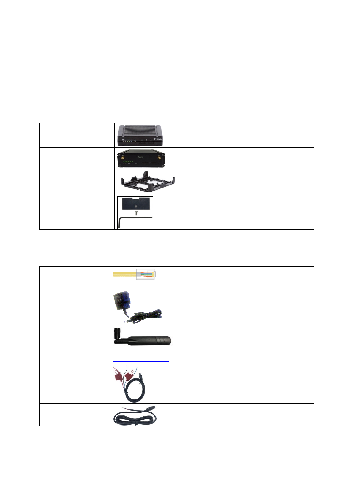
1 x GW1000 Series router
with carrier
1 x GW1000M Series router
1 x plastic carrier
1 x lockable SIM cover
Ethernet cable. RJ45
connector at both ends.
Power supply unit.
Right angle antenna for
3G/4G network.
Virtual Access supplies a wide range of antennas. Please visit our website:
www.virtualaccess.com or contact Virtual Access for more information.
1 x fused automotive
cable
1 x non-fused automotive
cable
2.11 Components
To enable and configure connections on your router, it must be correctly installed.
The routers contain an internal web server that you use for configurations. Before you
can access the internal web server and start the configuration, ensure the components
are correctly connected and that your PC has the correct networking setup.
2.11.1 Standard components
2: GW1000 Series hardware
Table 2: GW1000 Series router standard components
2.11.2 Optional components
Table 3: GW1000 Series router optional components
_______________________________________________________________________________________________________
© Virtual Access 2017
GW1000 Series User Manual
Issue: 1.9 Page 16 of 350
Page 17

_______________________________________________________________________________________________________
2.12 Inserting a SIM card
1. Ensure the unit is powered off.
2. Hold the SIM 1 card with the chip side facing down and the cut corner front left.
3. Gently push the SIM card into SIM slot 1 until it clicks in.
4. If using SIM 2 then hold the SIM with the cut corner front right
5. Gently push the SIM card into SIM slot 2 until it clicks in.
2.13 Connecting the SIM lock
Connect the SIM lock using the Allen key provided.
2.14 Connecting cables
Connect one end of the Ethernet cable into port A and the other end to your PC or
switch. For information on connecting cables for a vehicle installation, read chapter 4,
‘Installing a router into a vehicle’.
2: GW1000 Series hardware
2.15 Connecting the antenna
If you are connecting only one antenna, screw the antenna into the MAIN SMA
connector.
If you are using two antennas, screw the main antenna into the MAIN SMA connector
and the secondary antenna into the AUX SMA connector.
2.16 Powering up
The router takes approximately 2 minutes to boot up. During this time, the PWR/CONFIG
LED flashes in a double flash pattern – 2 quick fashes followed by a pause.
Other LEDs display different diagnostic patterns during boot up.
Booting is complete when the PWR/CONFIG LED stops double flashing and stays solid or
flashing steady, indicating the particular running configuration is loaded. Read the
chapter ‘GW1000 LED behaviour’, for PWR/CONFIG LED states.
_______________________________________________________________________________________________________
© Virtual Access 2017
GW1000 Series User Manual
Issue: 1.9 Page 17 of 350
Page 18

_______________________________________________________________________________________________________
Press duration
PWR/CONFIG LED
behaviour
Router behaviour on depress
0-3 seconds
On
Normal reset to running config. No special
LED activity.
Between 3 and 15 seconds
Flashing slowly
Releasing between 3-15 seconds switches
the router back to factory configuration.
Between 15 and 20 seconds
On
Releasing between 15-20 seconds performs
a normal reset to running config.
Between 20 seconds and 30 seconds
Flashing faster
Releasing between 20-30 seconds reboots
the router in recovery mode.
Over 30 seconds
On
Releasing after 30 seconds performs a
normal reset.
2.17 Reset button
The reset button is used to request a system reset.
When you press the reset button the PWR/CONFIG LED will display different patterns
depending on how long you press the button. The flashing patterns will be different for
the 2 flashing phases indicated below. The length of time you hold the reset button will
determine the router behaviour.
2: GW1000 Series hardware
2.17.1 Recovery mode
Recovery mode is a fail-safe mode where the router can load a default configuration
from the routers firmware. If your router goes into recovery mode, all config files are
kept intact. After the next reboot, the router will revert to the previous config file.
You can use recovery mode to manipulate the config files, but should only be used if all
other configs files are corrupt. If your router has entered recovery mode, contact your
local reseller for access information.
Table 4: GW1000 series router reset behaviour
_______________________________________________________________________________________________________
© Virtual Access 2017
GW1000 Series User Manual
Issue: 1.9 Page 18 of 350
Page 19
_______________________________________________________________________________________________________
3: GW1000 and GW1000M Series LED behaviour
3 GW1000 and GW1000M Series LED behaviour
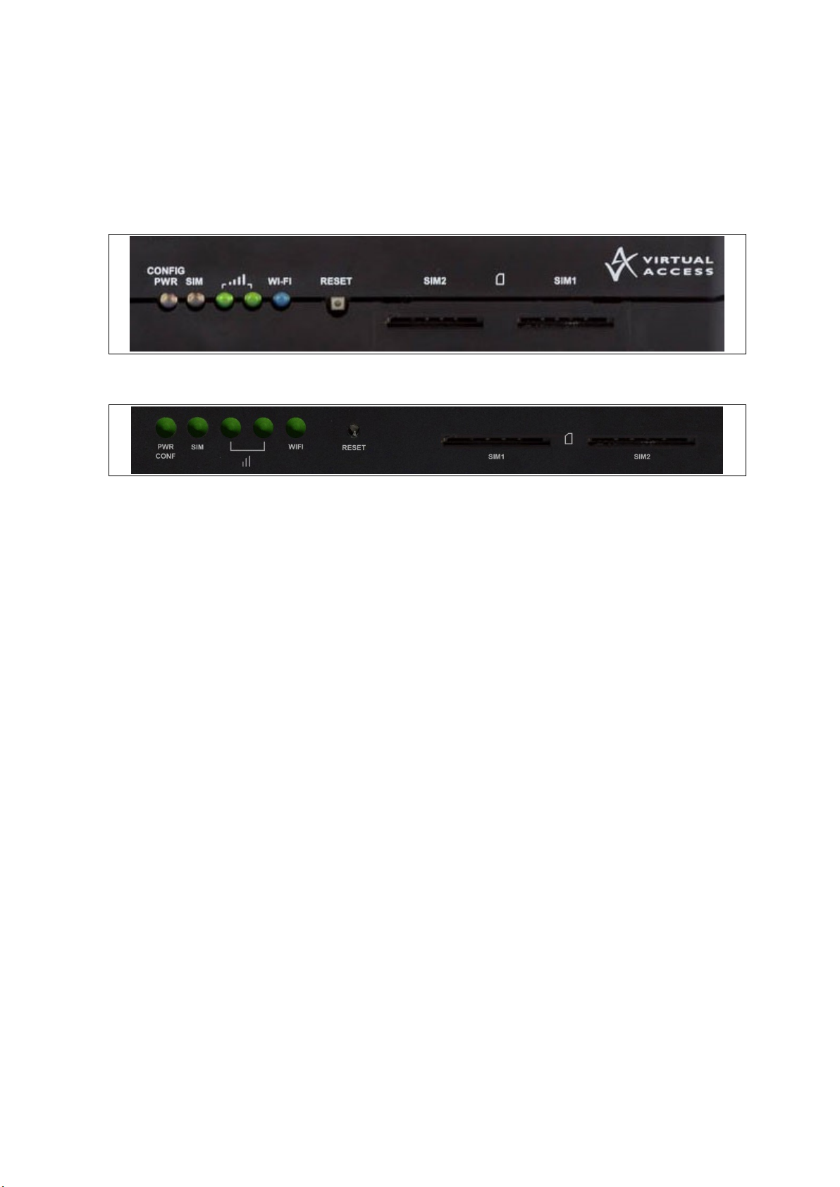
3.1 Main LED behaviour
There are five LEDs on the GW1000 and GW1000M Series router
Figure 5: LEDs on the GW1000 Series router
Figure 6: LEDs on the GW1000M Series router
The possible LED states are:
Off
Flashing slowing (2 flashes per second)
Flashing quickly (5 flashes per second)
Double flash (2 quick flashes then a pause)
On
_______________________________________________________________________________________________________
© Virtual Access 2017
GW1000 Series User Manual
Issue: 1.9 Page 19 of 350
Page 20

_______________________________________________________________________________________________________
Booting
The router takes approximately 2 minutes to boot up. During this time,
the power LED flashes.
Other LEDs display different diagnostic patterns during boot up.
Booting is complete when the power LED stops flashing and stays on
steady.
PWR/CONFIG
LED
Off
No power/boot loader does not exist.
Double flash
Unit is booting from power on.
Flashing slowly
Unit is in recovery mode.
Flashing quickly
Unit is in factory configuration.
On
Unit has completed booting up process and is in either config 1 or
config2.
SIM LEDs
Off
Not selected or SIM not inserted.
Flashing
SIM selected and data connection is being established.
On
SIM selected and registered on the network.
Signal LEDs
Both LEDs off
Not connected or signal strength <= -113dBm.
Left LED on
Right LED off
Connected and signal strength <= -89dBm.
Left LED off
Right LED on
Connected and signal strength between -89dBm and -69dBm.
Both LEDs on
Connected and signal strength >-69dBm.
WiFi LEDs
Off
WiFi not enabled.
Flashing
Data activity on WiFi interface.
On
WiFi is enabled.
Ethernet LED
(amber)
On
Physical Ethernet link detected
Flashing
Data is being transmitted/ received over the link.
3: GW1000 and GW1000M Series LED behaviour
The following table describes the possible LED behaviours and meanings on the GW1000
and GW1000M Series router.
Table 5: LED behaviour and descriptions
Note: when a data connection does not exist, none of the signal LEDs will light
regardless of signal strength.
3.2 GW1000 and GW1000M Series Ethernet port LED behaviour
The Ethernet port has two physical LEDs, one is green and one is amber. When looking
at the port, the amber LED is on the right and is the only active LED.
Figure 7: Ethernet LED
Table 6: Ethernet LED activity description
_______________________________________________________________________________________________________
© Virtual Access 2017
GW1000 Series User Manual
Issue: 1.9 Page 20 of 350
Page 21

_______________________________________________________________________________________________________
(1)
Connector: Molex Microfit 6circuit standard
(2)
Label 20mm wide
(3)
Each wire is 1.0mm square, with overall PVC sheath
Note:
Requires 5 amp fuse in series with red and blue wires
4: Installing a router into a vehicle
4 Installing a router into a vehicle
The type of cable you need depends on your application and vehicle. You will have
received either a fused or non-fused power cable for the installation.
4.1 Installing a router into a vehicle using a non-fused power cable
Install the router using the vehicle installation power cable 840-00076 provided.
Figure 8: 840-00076 3 core power cable
Table 7: Power cable descriptions
Connect the BLACK wire to a ground wire.
Connect the BLUE wire to a 12V switched vehicle ignition wire.
Connect the RED wire to a 12V permanent wire.
Plug the 6 pin connector into the router.
_______________________________________________________________________________________________________
© Virtual Access 2017
GW1000 Series User Manual
Issue: 1.9 Page 21 of 350
Page 22

_______________________________________________________________________________________________________
(1)
Connector: Molex Microfit 6circuit standard
(2)
Label 20mm wide
(3)
Each wire is 1.0mm square, with overall PVC sheath
(4)
Fuse
Note:
Requires 5 amp fuse in series with red and blue wires
4: Installing a router into a vehicle
4.2 Installing a router into a vehicle using a fused power cable
Install the router using the vehicle installation power cable 840-00105 provided.
Figure 9: 840-00105 3 core power cable
Table 8: Power cable descriptions
Connect the BLACK wire to a ground wire.
Connect the BLUE wire to a 12V switched vehicle ignition wire.
Connect the RED wire to a 12V permanent wire.
Plug the 6 pin connector into the router.
_______________________________________________________________________________________________________
© Virtual Access 2017
GW1000 Series User Manual
Issue: 1.9 Page 22 of 350
Page 23

_______________________________________________________________________________________________________
5: Factory configuration extraction from SIM card
5 Factory configuration extraction from SIM card
Virtual Access routers have a feature to update the factory configuration from a SIM
card. This allows you to change the factory configuration of a router when installing the
SIM.
1. Make sure the SIM card you are inserting has the required configuration written on it.
2. Ensure the router is powered off.
3. Hold the SIM 1 card with the chip side facing down and the cut corner front left.
4. Gently push the SIM card into SIM slot 1 until it clicks in.
5. Power up the router.
Depending on the model, the power LED and/or the configuration LED flash as usual.
The SIM LED starts flashing. This indicates the application responsible for 3G and
configuration extraction management is running. It also means the update of the
configuration is happening.
When the update is finished, depending on the model, the power LED and/or the
configuration LED blink alternatively and very fast for 20 seconds.
Note: factory configuration extraction is only supported on mobile modules that support
phone book operations.
_______________________________________________________________________________________________________
© Virtual Access 2017
GW1000 Series User Manual
Issue: 1.9 Page 23 of 350
Page 24
_______________________________________________________________________________________________________
Package
Sections
dropbear
dropbear
system
main
uhttpd
main
cert
PC IP address
192.168.100.100
Network mask
255.255.255.0
Default gateway
192.168.100.1
6: Accessing the router
6 Accessing the router
Access the router through the web interface or by using SSH. By default, Telnet is
disabled.
6.1 Configuration packages used
6.2 Accessing the router over Ethernet using the web interface
DHCP is disabled by default, so if you do not receive an IP address via DHCP, assign a
static IP to the PC that will be connected to the router.
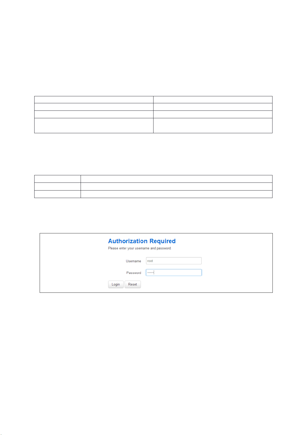
Assuming that the PC is connected to Port A on the router, in your internet browser, type
in the default local IP address 192.168.100.1, and press Enter. The Authorization page
appears.
Figure 10: The login page
The password may vary depending on the factory configuration the router has been
shipped with. The default settings are shown below. The username and password are
case sensitive.
In the username field, type root.
In the Password field, type admin.
Click Login. The Status page appears.
_____________________________________________________________________________________________________
© Virtual Access 2017
GW1000 Series User Manual
Issue: 1.9 Page 24 of 350
Page 25

_______________________________________________________________________________________________________
6.3 Accessing the router over Ethernet using an SSH client
You can also access the router over Ethernet, using Secure Shell (SSH) and optionally
over Telnet.
To access CLI over Ethernet start an SSH client and connect to the router’s management
IP address, on port 22: 192.168.100.1/24.
On the first connection, you may be asked to confirm that you trust the host.
6: Accessing the router
Figure 11: Confirming trust of the routers public key over SSH
Figure 12: SSH CLI logon screen
In the SSH CLI logon screen, enter the default username and password.
Username: root
Password: admin
6.3.1 SCP (Secure Copy Protocol)
As part of accessing the router over SSH, you can also use SCP protocol. Use the same
user authentication credentials as for SSH access. You can use SCP protocol to securely
manually transfer files from and to the router’s SCP server.
No dedicated SPC client is supported; select the SCP client software of your own choice.
_____________________________________________________________________________________________________
© Virtual Access 2017
GW1000 Series User Manual
Issue: 1.9 Page 25 of 350
Page 26
_______________________________________________________________________________________________________
Package
Sections
system
main
6.4 Accessing the router over Ethernet using a Telnet client
Telnet is disabled by default, when you enable Telnet, SSH is disabled.
To enable Telnet, enter:
root@VA_router: ~# /etc/init.d/dropbear disable
root@VA_router: ~# reboot -f
To re-enable SSH, enter:
root@VA_router: ~# /etc/init.d/dropbear enable
root@VA_router: ~# reboot -f
Note: As SSH is enabled by default, initial connection to the router to enable Telnet
must be established over SSH.
6: Accessing the router
6.5 Configuring the password
6.5.1 Configuration packages used
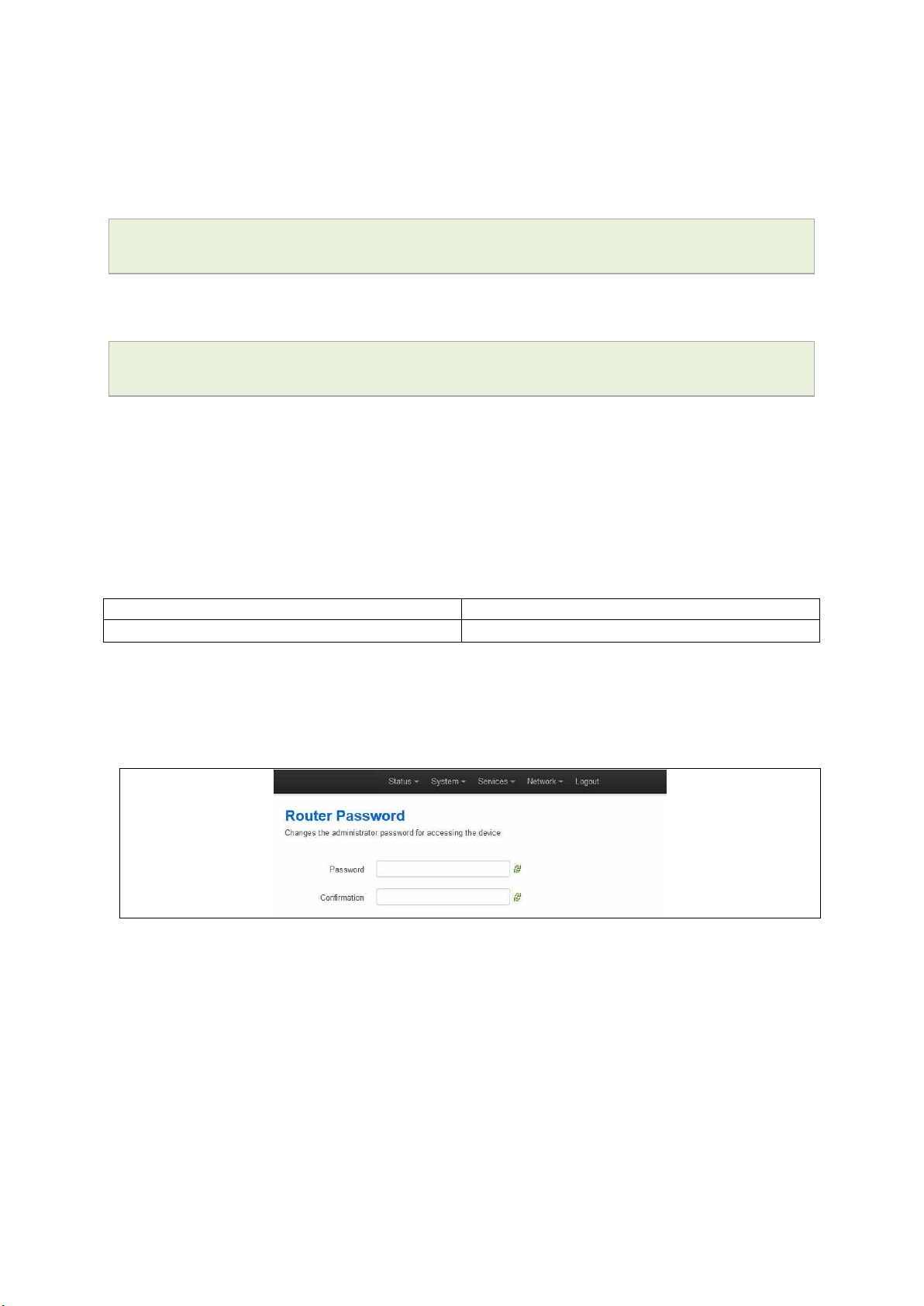
6.6 Configuring the password using the web interface
To change your password, in the top menu click System -> Administration. The
Administration page appears.
Figure 13: The router password section
In the Router Password section, type your new password in the password field and then
retype the password in the confirmation field.
Scroll down the page and click Save & Apply.
Note: the username ‘root’ cannot be changed.
_____________________________________________________________________________________________________
© Virtual Access 2017
GW1000 Series User Manual
Issue: 1.9 Page 26 of 350
Page 27

_______________________________________________________________________________________________________
Web Field/UCI/Package Option
Description
Web: Password
UCI: system.main.password
Opt: password
Defines the root password. The password is displayed encrypted
via the CLI using the ‘hashpassword’ option.
UCI: system.main.hashpassword
Opt: hashpassword
6.7 Configuring the password using UCI
The root password is displayed encrypted via the CLI using the hashpassword option.
root@VA_router:~# uci show system
system.main=system
system.main.hostname=VA_router
system.main.hashpassword=$1$jRX/x8A/$U5kLCMpi9dcahRhOl7eZV1
If changing the password via the UCI, enter the new password in plain text using the
password option.
root@VA_router:~# uci system.main.password=newpassword
6: Accessing the router
root@VA_router:~# uci commit
The new password will take effect after reboot and will now be displayed in encrypted
format via the hashpassword option.
6.8 Configuring the password using package options
The root password is displayed encrypted via the CLI using the hashpassword option.
root@VA_router:~# uci export system
package system
config system 'main'
option hostname 'VA_router'
option hashpassword '$1$wRYYiJOz$EeHN.GQcxXhRgNPVbqxVw
If changing the password via the UCI, enter the new password in plain text using the
password option.
package system
config system 'main'
option hostname 'VA_router'
option hashpassword '$1$wRYYiJOz$EeHN.GQcxXhRgNPVbqxVw
option password ‘newpassword’
The new password will take effect after reboot and will now be displayed in encrypted
format via the hashpassword option.
_____________________________________________________________________________________________________
© Virtual Access 2017
GW1000 Series User Manual
Issue: 1.9 Page 27 of 350
Page 28

_______________________________________________________________________________________________________
6.9 Accessing the device using RADIUS authentication
You can configure RADIUS authentication to access the router over SSH, web or local
console interface.
package system
config system 'main'
option hostname 'VirtualAccess'
option timezone 'UTC'
config pam_auth
option enabled 'yes'
option pamservice 'login'
option pammodule 'auth'
6: Accessing the router
option pamcontrol 'sufficient'
option type 'radius'
option servers '192.168.0.1:3333|test|20 192.168.2.5|secret|10'
config pam_auth
option enabled 'yes'
option pamservice 'sshd'
option pammodule 'auth'
option pamcontrol 'sufficient' it checks package
management_users
option type 'radius'
option servers '192.168.0.1:3333|test|20 192.168.2.5|secret|10'
config 'pam_auth'
option enabled 'yes'
option pamservice 'luci"
option pammodule 'auth'
option pamcontrol 'sufficient'
option type 'radius'
servers '192.168.0.1:3333|test|20 192.168.2.5|secret|10'
_____________________________________________________________________________________________________
© Virtual Access 2017
GW1000 Series User Manual
Issue: 1.9 Page 28 of 350
Page 29

_______________________________________________________________________________________________________
UCI/Package Option
Description
UCI: system.@pam_auth[0].enabled=yes
Opt: enabled
Enables and disables RADIUS configuration sections.
yes
Enables following RADIUS
configuration section.
no
Disables following RADIUS
configuration section.
UCI: system.@pam_auth[0].pamservice
Opt: pamservice
Selects the method which users should be authenticated by.
login
User connecting over console cable.
sshd
User connecting over SSH.
luci
User connecting over web.
UCI: system.@pam_auth[0].pamcontrol
Opt: pamcontrol
Specifies authentication behaviour after authentication fails or
connection to RADIUS server is broken.
Sufficient
First authenticates against remote
RADIUS if password authentication
fails then it tries local database
(user defined in package
management_users)
Required
If either authentication fails or
RADIUS server is not reachable
then user is not allowed to access
the router.
[success=done
new_authtok_reqd=done
authinfo_unavail=ignore
default=die]
Local database is only checked if
RADIUS server is not reachable.
UCI:
system.@pam_auth[0].pammodule.auth
Opt: pammodule
Enables user authentication.
UCI: system.@pam_auth[0].type.radius
Opt: type
Specifies the authentication method.
UCI: system.@pam_auth[0].servers
Opt: servers
Specifies the RADIUS server or multiple servers along with port
number and password. The example below explains the syntax.
192.168.0.1:3333|test|20 192.168.2.5|secret|10
6: Accessing the router
Table 9: Information table for RADIUS authentication
6.10 Accessing the device using TACACS+ authentication
TACACS+ authentication can be configured for accessing the router over SSH, web or
local console interface.
package system
config system 'main'
option hostname 'VirtualAccess'
option timezone 'UTC'
config pam_auth
option enabled 'yes'
option pamservice 'sshd'
_____________________________________________________________________________________________________
© Virtual Access 2017
GW1000 Series User Manual
Issue: 1.9 Page 29 of 350
Page 30

_______________________________________________________________________________________________________
6: Accessing the router
option pammodule 'auth'
option pamcontrol 'sufficient'
option type 'tacplus'
option servers '192.168.0.1:49|secret'
config pam_auth
option enabled 'yes'
option pamservice 'sshd'
option pammodule 'account'
option pamcontrol 'sufficient'
option type 'tacplus'
option servers '192.168.0.1:49|secret'
option args 'service=ppp'
config pam_auth
option enabled 'yes'
option pamservice 'sshd'
option pammodule 'session'
option pamcontrol 'sufficient'
option type 'tacplus'
option servers '192.168.0.1:49|secret'
option args 'service=ppp'
config pam_auth
option enabled 'yes'
option pamservice 'luci'
option pammodule 'auth'
option pamcontrol 'sufficient'
option type 'tacplus'
option servers '192.168.0.1:49|secret'
config pam_auth
option enabled 'yes'
option pamservice 'luci'
option pammodule 'account'
option pamcontrol 'sufficient'
option type 'tacplus'
_____________________________________________________________________________________________________
© Virtual Access 2017
GW1000 Series User Manual
Issue: 1.9 Page 30 of 350
Page 31

_______________________________________________________________________________________________________
6: Accessing the router
option servers '192.168.0.1:49|secret'
option args 'service=ppp'
config pam_auth
option enabled 'yes'
option pamservice 'luci'
option pammodule 'session'
option pamcontrol 'sufficient'
option type 'tacplus'
option servers '192.168.0.1:49|secret'
option args 'service=ppp'
config pam_auth
option enabled 'yes'
option pamservice 'login'
option pammodule 'auth'
option pamcontrol 'sufficient'
option type 'tacplus'
option servers '192.168.0.1:49|secret'
config pam_auth
option enabled 'yes'
option pamservice 'login'
option pammodule 'account'
option pamcontrol 'sufficient'
option type 'tacplus'
option servers '192.168.0.1:49|secret'
option args 'service=ppp'
config pam_auth
option enabled 'yes'
option pamservice 'login'
option pammodule 'session'
option pamcontrol 'sufficient'
option type 'tacplus'
option servers '192.168.0.1:49|secret'
option args 'service=ppp'
_____________________________________________________________________________________________________
© Virtual Access 2017
GW1000 Series User Manual
Issue: 1.9 Page 31 of 350
Page 32

_______________________________________________________________________________________________________
UCI/Package Option
Description
UCI: system.@pam_auth[0].enabled=yes
Opt: enabled
Enables and disables TACACS configuration sections.
yes
Enables following TACACS
configuration section.
no
Disables following TACACS
configuration section.
UCI: system.@pam_auth[0].pamservice
Opt: pamservice
Selects the method which users should be authenticated by.
login
User connecting over console cable.
sshd
User connecting over SSH.
luci
User connecting over web.
UCI: system.@pam_auth[0].pamcontrol
Opt: pamcontrol
Specifies authentication behaviour after authentication fails or
connection to TACACS server is broken.
Sufficient
First authenticates against
remote TACACS if password
authentication fails then it
tries local database (user
defined in package
management_users)
Required
If either authentication fails
or TACACS server is not
reachable then user is not
allowed to access the router.
[success=done
new_authtok_reqd=done
authinfo_unavail=ignore
default=die]
Local database is only
checked if TACACS server is
not reachable.
UCI:
system.@pam_auth[0].pammodule.auth
Opt: pammodule
Selects which TACACS module this part of configuration relates
to.
auth
auth module provides the actual
authentication and sets credentials
account
account module checks to make sure
that access is allowed for the user
session
session module performs additional
tasks which are needed to allow
access
system.@pam_auth[0].type=tacplus
Opt: type
Specifies the authentication method.
UCI: system.@pam_auth[0].servers
Opt: servers
Specifies the TACACS servers along with port number and
password. The example below explains the syntax.
192.168.0.1:49|secret '
UCI:
system.@pam_auth[1].args=service=ppp
Opt: args
Additional arguments to pass to TACACS serer.
6: Accessing the router
Table7: Information table for TACACS authentication
6.11 SSH
SSH allows you to access remote machines over text based shell sessions. SSH uses
public key cryptography to create a secure connection. These connections allow you to
issue commands remotely via a command line.
_____________________________________________________________________________________________________
© Virtual Access 2017
GW1000 Series User Manual
Issue: 1.9 Page 32 of 350
Page 33

_______________________________________________________________________________________________________
Package
Sections
dropbear
dropbear
The router uses a package called Dropbear to configure the SSH server on the box. You
can configure Dropbear via the web interface or through an SSH connection by editing
the file stored on: /etc/config_name/dropbear.
6.11.1 Configuration packages used
6.11.2 SSH access using the web interface
In the top menu, click System -> Administration. The Administration page appears.
Scroll down to the SSH Access section.
6: Accessing the router
Figure 14: The SSH access section
_____________________________________________________________________________________________________
© Virtual Access 2017
GW1000 Series User Manual
Issue: 1.9 Page 33 of 350
Page 34

_______________________________________________________________________________________________________
Web Field/UCI/Package Option
Description
Basic settings
Web: Interface
UCI: dropbear.@dropbear[0].Interface
Opt: interface
Listens only on the selected interface. If unspecified is checked,
listens on all interfaces. All configured interfaces will be displayed
via the web GUI.
(unspecified)
listens on all interfaces.
Range
Configured interface names.
Web: Port
UCI: dropbear.@dropbear[0].Port
Opt: port
Specifies the listening port of the Dropbear instance.
22 Range
0-65535
Web: Password authentication
UCI:
dropbear.@dropbear[0].PasswordAuth
Opt: PasswordAuth
If enabled, allows SSH password authentication.
0
Disabled.
1
Enabled.
Web: Allow root logins with password
UCI:
dropbear.@dropbear[0].RootPasswordAuth
Opt: RootPasswordAuth
Allows the root user to login with password.
0
Disabled.
1
Enabled.
Web: Gateway ports
UCI:
dropbear.@dropbear[0].GatewayPorts
Opt: GatewayPorts
Allows remote hosts to connect to local SSH forwarded ports.
0
Disabled.
1
Enabled.
Web: Idle Session Timeout
UCI: dropbear.@dropbear[0].IdleTimeout
Opt: IdleTimeout
Defines the idle period where remote session will be closed after
the allocated number of seconds of inactivity.
30
30 seconds.
Range
Web: n/a
UCI: dropbear.@dropbear[0]. BannerFile
Opt: BannerFile
Defines a banner file to be displayed during login.
/etc/banner
Range
Web: n/a
UCI:
dropbear.@dropbear[0].MaxLoginAttempts
Opt: MaxLoginAttempts
Specifies maximum login failures before session terminates
10 0-infinite
6: Accessing the router
Table 10: Information table for SSH access settings
6.12 Package dropbear using UCI
root@VA_router:~# uci show dropbear
dropbear.@dropbear[0]=dropbear
dropbear.@dropbear[0].PasswordAuth=on
dropbear.@dropbear[0].RootPasswordAuth=on
dropbear.@dropbear[0].GatewayPorts=0
dropbear.@dropbear[0].IdleTimeout=30
dropbear.@dropbear[0].Port=22
dropbear.@dropbear[0].MaxLoginAttempts=3
Package dropbear using package options
_____________________________________________________________________________________________________
© Virtual Access 2017
GW1000 Series User Manual
Issue: 1.9 Page 34 of 350
Page 35

_______________________________________________________________________________________________________
root@VA_router:~# uci export dropbear
package dropbear
config dropbear'
option PasswordAuth 'on'
option RootPasswordAuth 'on'
option Port '22'
option GatewayPorts ‘0’
option IdleTimeout ‘30’
option MaxLoginAttempts '3'
6.13 Certs and private keys
Certificates are used to prove ownership of a public key. They contain information about
the key, its owner’s ID, and the digital signature of an individual that has verified the
content of the certificate.
6: Accessing the router
In asymmetric cryptography, public keys are announced to the public, and a different
private key is kept by the receiver. The public key is used to encrypt the message, and
the private key is used to decrypt it.
To access certs and private keys, in the top menu, click System -> Administration.
The Administration page appears. Scroll down to the Certs & Private Keys section.
Figure 15: The certificates & private keys section
This section allows you to upload any certificates and keys that you may have stored.
There is support for IPSec, OpenVPN and VA certificates and keys.
If you have generated your own SSH public keys, you can input them in the SSH Keys
section, for SSH public key authentication.
_____________________________________________________________________________________________________
© Virtual Access 2017
GW1000 Series User Manual
Issue: 1.9 Page 35 of 350
Page 36

_______________________________________________________________________________________________________
Package
Sections
uhttpd
main
cert
Main Settings
Server configurations
Certificate Settings
SSL certificates.
Figure 16: The SSH-keys box
6.14 Configuring a router’s web server
The router’s web server is configured in package uhttpd. This file defines the behaviour
of the server and default values for certificates generated for SSL operation. uhttpd
supports multiple instances, that is, multiple listen ports, each with its own document
root and other features, as well as cgi and lua. There are two sections defined:
Main: this uHTTPd section contains general server settings.
Cert: this section defines the default values for SSL certificates.
6: Accessing the router
6.14.1 Configuration packages used
To configure the router’s HTTP server parameters, in the top menu, select Services ->
HTTP Server. The HTTP Server page has two sections.
_____________________________________________________________________________________________________
© Virtual Access 2017
GW1000 Series User Manual
Issue: 1.9 Page 36 of 350
Page 37

_______________________________________________________________________________________________________
Web Field/UCI/Package Option
Description
Web: Listen Address and Port
UCI: uhttpd.main.listen_http
Opt: list listen_http
Specifies the ports and addresses to listen on for plain HTTP
access. If only a port number is given, the server will attempt to
serve both IPv4 and IPv6 requests.
0.0.0.0:80
Bind at port 80 only on IPv4
interfaces.
[::]:80
Bind at port 80 only on IPv6
interfaces
Range
IP address and/or port
Web: Secure Listen Address and Port
UCI: uhttpd.main.listen_https
Opt: list listen_https
Specifies the ports and address to listen on for encrypted HTTPS
access. The format is the same as listen_http.
0.0.0.0:443
Bind at port 443 only
[::]:443
Range
IP address and/or port
Web: Home path
UCI: uhttpd.main.home
Opt: home
Defines the server document root.
/www
Range
Web: Cert file
UCI: uhttpd.main.cert
Opt: cert
ASN.1/DER certificate used to serve HTTPS connections. If no
listen_https options are given the key options are ignored.
/etc/uhttpd.crt
Range
Web: Key file
UCI: uhttpd.main.key
Opt: key
ASN.1/DER private key used to serve HTTPS connections. If no
listen_https options are given the key options are ignored.
/etc/uhttpd.key
Range
6.14.2 Main settings
6: Accessing the router
Figure 17: HTTP server settings
_____________________________________________________________________________________________________
© Virtual Access 2017
GW1000 Series User Manual
Issue: 1.9 Page 37 of 350
Page 38

_______________________________________________________________________________________________________
Web: CGI profile
UCI: uhttpd.main.cgi_prefix
Opt: cgi_prefix
Defines the prefix for CGI scripts, relative to the document root.
CGI support is disabled if this option is missing.
/cgi-bin
Range
Web: N/A
UCI: uhttpd.main.lua_prefix
Opt: lua_prefix
Defines the prefix for dispatching requests to the embedded lua
interpreter, relative to the document root. Lua support is
disabled if this option is missing.
/luci
Range
Web: N/A
UCI: uhttpd.main.lua_handler
Opt: lua_handler
Specifies the lua handler script used to initialise the lua runtime
on server start.
/usr/lib/lua/luci/sgi/uhttpd.lua
Range
Web: Script timeout
UCI: uhttpd.main.script_timeout
Opt: script_timeout
Sets the maximum wait time for CGI or lua requests in seconds.
Requested executables are terminated if no output was
generated.
60
Range
Web: Network timeout
UCI: uhttpd.main.network_timeout
Opt: network_timeout
Maximum wait time for network activity. Requested executables
are terminated and connection is shut down if no network activity
occured for the specified number of seconds.
30 Range
Web: N/A
UCI: uhttpd.main.realm
Opt: realm
Defines basic authentication realm when prompting the client for
credentials (HTTP 400).
OpenWrt
Range
Web: N/A
UCI: uhttpd.main.config
Opt: config
Config file in Busybox httpd format for additional settings.
Currently only used to specify basic auth areas.
/etc/http.conf
Range
Web: N/A
UCI: uhttpd.main.index_page
Opt: index_page
Index file to use for directories, for example, add index.php when
using php.
Range
Web: N/A
UCI: httpd.main.error_page
Opt: error_page
Virtual URL of file of CGI script to handle 404 requests. Must
begin with ‘/’ (forward slash).
Range
Web: N/A
UCI: uhttpd.main.no_symlinks
Opt: no_symlinks
Does not follow symbolic links if enabled.
0
Disabled.
1
Enabled.
Web: N/A
UCI: uhttpd.main.no_dirlists
Opt: no_symlinks
Does not generate directory listings if enabled.
0
Disabled.
1
Enabled.
6: Accessing the router
_____________________________________________________________________________________________________
© Virtual Access 2017
GW1000 Series User Manual
Issue: 1.9 Page 38 of 350
Page 39

_______________________________________________________________________________________________________
Web: rfc 1918 filter
UCI: uhttpd.main.rfc1918_filter=1
Opt: rfc1918_filter
Enables option to reject requests from RFC1918 IPs to public
server IPs (DNS rebinding counter measure).
0
Disabled.
1
Enabled.
Table 11: Information table for http server basic settings
6.14.3 HTTP server using UCI
Multiple sections of the type uhttpd may exist. The init script will launch one webserver
instance per section.
A standard uhttpd configuration is shown below.
root@VA_router:~# uci show uhttpd
uhttpd.main=uhttpd
uhttpd.main.listen_http=0.0.0.0:80
uhttpd.main.listen_https=0.0.0.0:443
6: Accessing the router
uhttpd.main.home=/www
uhttpd.main.rfc1918_filter=1
uhttpd.main.cert=/etc/uhttpd.crt
uhttpd.main.key=/etc/uhttpd.key
uhttpd.main.cgi_prefix=/cgi-bin
uhttpd.main.script_timeout=60
uhttpd.main.network_timeout=30
uhttpd.main.config=/etc/http.conf
HTTP server using package options
root@VA_router:~# uci export dropbear
config uhttpd 'main'
list listen_http '0.0.0.0:80'
list listen_https '0.0.0.0:443'
option home '/www'
option rfc1918_filter '1'
option cert '/etc/uhttpd.crt'
option key '/etc/uhttpd.key'
option cgi_prefix '/cgi-bin'
option script_timeout '60'
option network_timeout '30'
option config '/etc/http.conf'
_____________________________________________________________________________________________________
© Virtual Access 2017
GW1000 Series User Manual
Issue: 1.9 Page 39 of 350
Page 40

_______________________________________________________________________________________________________
Web Field/UCI/Package Option
Description
Web: Days
UCI: uhttpd.px5g.days
Opt: days
Validity time of the generated certificates in days.
730 Range
Web: Bits
UCI: uhttpd.px5g.bits
Opt: bits
Size of the generated RSA key in bits.
1024
Range
Web: Country
UCI: uhttpd.px5g.country
Opt: country
ISO code of the certificate issuer.
Web: State
UCI: uhttpd.px5g.state
Opt: state
State of the certificate issuer.
Web: Location
UCI: uhttpd.px5g.location
Opt: location
Location or city of the certificate user.
Web: Commonname
UCI: uhttpd.commonname
Opt: commonname
Common name covered by the certificate. For the purposes of
secure Activation, this must be set to the serial number (Eth0
MAC address) of the device.
6.14.4 HTTPs server certificate settings
To configure HTTPs server certificate settings, in the top menu, select Services ->
HTTP Server. Scroll down to the Certificate Settings section.
Figure 18: HTTP server certificate settings
6: Accessing the router
Table 12: Information table for HTTP server certificate settings
_____________________________________________________________________________________________________
© Virtual Access 2017
GW1000 Series User Manual
Issue: 1.9 Page 40 of 350
Page 41

_______________________________________________________________________________________________________
6.14.5 HTTPs server using UCI
root@VA_router:~# uci show uhttpd.px5g
uhttpd.px5g=cert
uhttpd.px5g.days=3650
uhttpd.px5g.bits=1024
uhttpd.px5g.country=IE
uhttpd.px5g.state=Dublin
uhttpd.px5g.location=Dublin
uhttpd.px5g.commonname=00E0C8000000
HTTPs server using package options
root@VA_router:~# uci export uhttpd
package uhttpdconfig 'cert' 'px5g'
option 'days' '3650'
6: Accessing the router
option 'bits' '1024'
option 'state' 'Dublin'
option 'location' 'Dublin'
option 'commonname' '00E0C8000000'
6.15 Basic authentication (httpd conf)
For backward compatibility reasons, uhttpd uses the file /etc/httpd.conf to define
authentication areas and the associated usernames and passwords. This configuration
file is not in UCI format.
Authentication realms are defined in the format prefix:username:password with one
entry and a line break.
Prefix is the URL part covered by the realm, for example, cgi-bin to request basic auth
for any CGI program.
Username specifies the username a client has to login with.
Password defines the secret password required to authenticate.
The password can be either in plain text format, MD5 encoded or in the form $p$user
where the user refers to an account in /etc/shadow or /etc/passwd.
If you use $p$… format, uhttpd will compare the client provided password against the
one stored in the shadow or passwd database.
_____________________________________________________________________________________________________
© Virtual Access 2017
GW1000 Series User Manual
Issue: 1.9 Page 41 of 350
Page 42

_______________________________________________________________________________________________________
6.16 Securing uhttpd
By default, uhttpd binds to 0.0.0.0 which also includes the WAN port of your router. To
bind uhttpd to the LAN port only you have to change the listen_http and listen_https
options to your LAN IP address.
To get your current LAN IP address, enter:
uci get network.lan.ipaddr
Then modify the configuration appropriately:
uci set uhttpd.main.listen_http='192.168.1.1:80'
uci set uhttpd.main.listen_https='192.168.1.1:443'
config 'uhttpd' 'main'
list listen_http 192.168.1.1:80
list listen_https 192.168.1.1:443
6: Accessing the router
_____________________________________________________________________________________________________
© Virtual Access 2017
GW1000 Series User Manual
Issue: 1.9 Page 42 of 350
Page 43

_______________________________________________________________________________________________________
Package
Sections
ddns
service
7 Configuring Dynamic DNS
7.1 Overview
Dynamic DNS (DDNS) functionality on a Virtual Access router will dynamically perform
DDNS updates to a server so it can associate an IP address with a correctly associated
DNS name. Users can then contact a machine, router, device and so on with a DNS
name rather than a dynamic IP address.
An account is required with the provider, and one or more domain names are associated
with that account. A dynamic DNS client on the router monitors the public IP address
associated with an interface and whenever the IP address changes, the client notifies the
DNS provider to update the corresponding domain name.
When the DNS provider responds to queries for the domain name, it sets a low lifetime,
typically a minute or two at most, on the response so that it is not cached. Updates to
the domain name are thus visible throughout the whole Internet with little delay.
Note: most providers impose restrictions on how updates are handled: updating when
no change of address occurred is considered abusive and may result in an account being
blocked. Sometimes, addresses must be refreshed periodically, for example, once a
month, to show that they are still in active use.
7: Configuring Dynamic DNS
7.2 Configuration packages used
7.3 Configuring Dynamic DNS using the web interface
In the top menu, select Services -> Dynamic DNS. The Dynamic DNS Configuration
page appears.
Figure 19: The Dynamic DNS configuration page
Enter a text name that will be used for the dynamic DNS section in the configuration.
Select Add. The Dynamic DNS configuration options appear.
_____________________________________________________________________________________________________
© Virtual Access 2017
GW1000 Series User Manual
Issue: 1.9 Page 43 of 350
Page 44

_______________________________________________________________________________________________________
Web Field/UCI/Package Option
Description
Web: Enable
UCI: ddns.<name>.enabled
Opt: enabled
Enables a Dynamic DNS entry on the router.
0
Disabled.
1
Enabled
Web: Service
UCI: ddns.<name>.service_name
Opt: service_name
Defines the Dynamic DNS provider
Web: Customer update-URL
UCI: ddns.<name>.update_url
Opt: update_url
Defines the customer DNS provider.
Displayed when the service is set to custom in the web UI.
Web: Hostname
UCI: ddns.<name>.domain
Opt: domain
Defines the fully qualified domain name associated with this
entry. This is the name to update with the new IP address as
needed.
Web: Username
UCI: ddns.<name>.username
Opt: username
Defines the user name to use for authenticating domain updates
with the selected provider.
Web: Password
UCI: ddns.<name>.password
Opt: password
Defines the password to use for authenticating domain name
updates with the selected provider.
Web: Source of IP address
UCI: ddns.<name>.ip_source
Opt: ip_source
Defines the type of interface whose IP needs to be updated.
network
IP is a associated with a network configuration.
interface
IP is associated with an interface.
web
IP is associated with a URL.
7.3.1 Dynamic DNS settings
7: Configuring Dynamic DNS
Figure 20: The dynamic DNS main settings page
_____________________________________________________________________________________________________
© Virtual Access 2017
GW1000 Series User Manual
Issue: 1.9 Page 44 of 350
Page 45

_______________________________________________________________________________________________________
Web: Network
UCI: ddns.<name>.ip_network
Opt: ip_network
Defines the network whose IP needs to be updated.
Displayed when the Source of IP address option is set to
network.
All the configured network interfaces will be shown.
Web: Inteface
UCI: ddns.<name>.ip_interface
Opt: ip_interface
Defines the interface whose IP needs to be updated.
Displayed when the Source of IP address option is set to
interface.
All the configured interfaces will be shown.
Web: URL
UCI: ddns.<name>.ip_url
Opt: ip_url
Defines the URL where the IP downloaded from.
Displayed when the Source of IP address option is set to URL.
Web: Check for changed IP every
UCI: ddns.<name>.check_interval
Opt: check_interval
Defines how often to check for an IP change. Used in conjunction
with check_unit.
10 . Range
Web: Check-time unit
UCI: ddns.<name>.check_unit
Opt: check_unit
Defines the time unit to use for check for an IP change. Used in
conjunction with check_interval.
minutes
hours
Web: Force update every
UCI: ddns.<name>.force_interval
Opt: force_interval
Defines how often to force an IP update to the provider. Used in
conjunction with force_unit.
72
Disabled.
Range
Enabled
Web: Force-time unit
UCI: ddns.<name>.force_unit
Opt: force_unit
Defines the time unit to use for check for an IP change. Used in
conjunction with force_interval.
minutes
hours
Web: Listen on
UCI: ddns.<name>.interface
Opt: interface
Defines the interface for ddns monitoring. Typically this will be
the same as the interface whose IP is being updated – as defined
ip_network or ip_interface
All configured interfaces will be displayed.
7: Configuring Dynamic DNS
Table 13: Information table for dynamic DNS settings
7.4 Dynamic DNS using UCI
Dynamic DNS uses the ddns package /etc/config/ddns
7.4.1 UCI commands for DDNS
root@VA_router:~# uci show ddns
ddns.ddns1=service
ddns.ddns1.enabled=1
ddns.ddns1.service_name=dyndns.org
ddns.ddns1.domain=fqdn_of_interface
ddns.ddns1.username=testusername
ddns.ddns1.password=testpassword
ddns.ddns1.ip_source=network
ddns.ddns1.ip_network=dsl0
ddns.ddns1.check_interval=10
_____________________________________________________________________________________________________
© Virtual Access 2017
GW1000 Series User Manual
Issue: 1.9 Page 45 of 350
Page 46

_______________________________________________________________________________________________________
7: Configuring Dynamic DNS
ddns.ddns1.check_unit=minutes
ddns.ddns1.force_interval=72
ddns.ddns1.force_unit=hours
ddns.ddns1.interface=dsl0
Package options for DDNS
root@VA_router:~# uci export ddns
package ddns
config service 'ddns1'
option enabled '1'
option service_name 'dyndns.org'
option domain 'fqdn_of_interface'
option username 'test'
option password 'test'
option ip_source 'network'
option ip_network 'dsl0'
option check_interval '10'
option check_unit 'minutes'
option force_interval '72'
option force_unit 'hours'
option interface 'dsl0'
_____________________________________________________________________________________________________
© Virtual Access 2017
GW1000 Series User Manual
Issue: 1.9 Page 46 of 350
Page 47

_______________________________________________________________________________________________________
Package
Sections
system
main
timeserver
Section
Description
General settings
Configure host name, local time and time zone.
Logging
Configure a router to log to a server. You can configure a Syslog client in this
section.
Language and Style
Configure the router’s web language and style.
Time synchronization
Configure the NTP server in this section.
8 System settings
The system section contains settings that apply to the most basic operation of the
system, such as the host name, time zone, logging details, NTP server, language and
style.
The host name appears in the top left hand corner of the interface menu. It also appears
when you open a Telnet or SSH session.
Note: this document shows no host name in screen grabs. Throughout the document we
use the host name ‘VA_router’.
The system configuration contains a logging section for the configuration of a Syslog
client.
8.1 Configuration package used
8: System settings
8.2 Configuring system properties
To set your system properties, in the top menu, click System. There are four sections in
the System page.
8.2.1 General settings
Figure 21: General settings in system properties
_____________________________________________________________________________________________________
© Virtual Access 2017
GW1000 Series User Manual
Issue: 1.9 Page 47 of 350
Page 48

_______________________________________________________________________________________________________
Web Field/UCI/Package Option
Description
Web: Local Time
Sets the local time and syncs with browser. You can manually
configure on CLI, using:
date –s YYYY.MM.DD-hh:mm:ss
Web: hostname
UCI: system.main.hostname
Opt: hostname
Specifies the hostname for this system.
Web: Timezone
UCI: system.main.timezone
Opt: timezone
Specifies the time zone that the date and time should be
rendered in by default.
Web: n/a
UCI: system.main.timezone
Opt: time_save_interval_min
Defines the interval in minutes to store the local time for use on
next reboot.
10m
Web Field/UCI/Package Option
Description
Web: System log buffer size
UCI: system.main.log_size
Opt: log_size
Log buffer size in KB.
Range
16
16 KB
Web: External system log server
UCI: system.main.log_ip
Opt: log_ip
External syslog server IP address.
Range
0.0.0.0
Web: External system log server port
UCI: system.main.log_port
Opt: log_port
External syslog server port number.
Range
514
8.2.2 Logging
8: System settings
Table 14: Information table for general settings section
Figure 22: The logging section in system properties
_____________________________________________________________________________________________________
© Virtual Access 2017
GW1000 Series User Manual
Issue: 1.9 Page 48 of 350
Page 49

_______________________________________________________________________________________________________
Web: Log output level
UCI: system.main.conloglevel
Opt: conloglevel
Sets the maximum log output level severity for system events.
System events are written to the system log. Messages with a lower
level or level equal to the configured level are displayed in the console
using the logread command, or alternatively written to flash, if
configured to do so.
Web value
Description
UCI
Debug
Information useful to developers for
debugging the application.
8
Info
Normal operational messages that
require no action.
7
Notice
Events that are unusual, but not
error conditions.
6
Warning
May indicate that an error will occur
if action is not taken.
5
Error
Error conditions
4
Critical
Critical conditions
3
Alert
Should be addressed immediately
2
Emergency
System is unusable
1
Web: Cron Log Level
UCI: system.main.cronloglevel
Opt: cronloglevel
Sets the maximum log level for kernel messages to be logged to the
console. Only messages with a level lower, or level equal to the
configured level will be printed to the console.
Web value
Description
UCI
Normal
Normal operation messages
8
Warning
Error messages
9
Debug
Debug messages
5
Web: n/a
UCI: system.main.log_file
Opt: log_file
Since logread is only small in size it can be beneficial to write system
events to flash. This option defines the file path to write the events.
Set to ‘root/syslog.messages’
Web: n/a
UCI: system.main.log_type
Opt: log_type
Defines whether to write the system events to a file rather than
logread. Set to ‘file’ to write to the file configured under log_file
option.
Web: n/a
UCI: system.main.log_file_count
Opt: log_file_count
Defines the number of archive syslog files to store in flash. When
configured above to write to /root.syslog.messages files will be stored
at /root/syslog.messages,x (where x starts at 0).
Range
1 Stores 1 archive log file in flash
8: System settings
Table 15: Information table for the logging section
_____________________________________________________________________________________________________
© Virtual Access 2017
GW1000 Series User Manual
Issue: 1.9 Page 49 of 350
Page 50
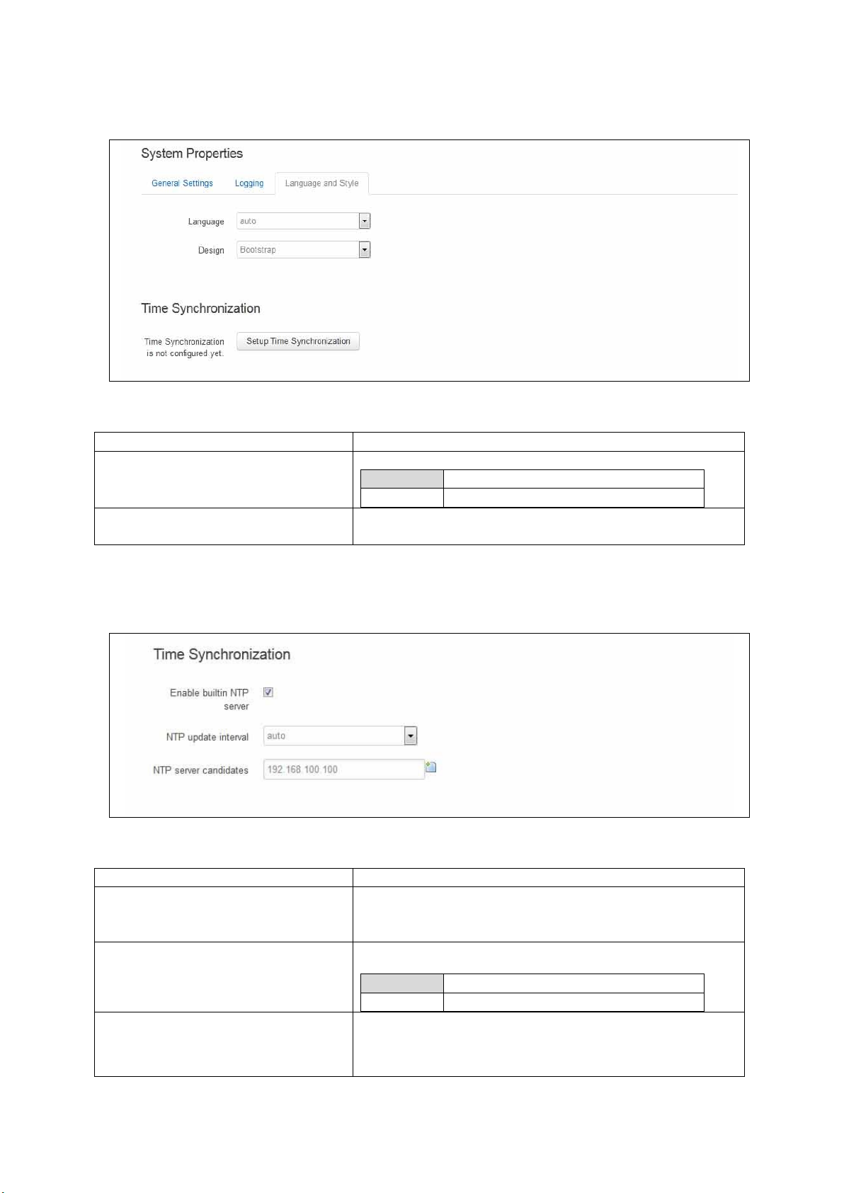
_______________________________________________________________________________________________________
Web Field/UCI/Package Option
Description
Language
Sets the language to ‘auto’ or ‘English’.
Auto
English
Design
Sets the router’s style.
Web Field/UCI/Package Option
Description
Web: Enable built-in NTP Server
UCI: system.ntp
Opt: config timeserver
Enables NTP server.
Web: NTP update interval
UCI: system.ntp.interval_hours
Opt: interval_hours
Specifies interval of NTP requests in hours. Default value set to
auto.
auto
Range
auto; 1-23
Web: NTP server candidates
UCI: system.ntp.server
Opt: list server
Defines the list of NTP servers to poll the time from. If the list is
empty, the built in NTP daemon is not started. Multiple servers
can be configured and are separated by a space if using UCI.
By default all fields are set to 0.0.0.0.
8.2.3 Language and style
Figure 23: The language and style section in system properties
8: System settings
Table 16: Information table for the language and style page
8.2.4 Time synchronization
Figure 24: The time synchronization section in system properties
_____________________________________________________________________________________________________
© Virtual Access 2017
GW1000 Series User Manual
Issue: 1.9 Page 50 of 350
Page 51

_______________________________________________________________________________________________________
8.2.5 System reboot
The router can be configured to reboot immediately, or scheduled to reboot a configured
time in the future.
In the top menu, select System -> Reboot. The System page appears.
Ensure you have saved all your configuration changes before you reboot.
8: System settings
Table 17: Information table for time synchronization section
Check the Reboot now check box and then click Reboot.
8.3 System settings using UCI
root@VA_router:~# uci show system
system.main=system
system.main.hostname=VA_router
system.main.timezone=UTC
system.main.log_ip=1.1.1.1
system.main.log_port=514
system.main.conloglevel=8
system.main.cronloglevel=8
system.ntp.interval_hours=auto
system.ntp.server=0.VA_router.pool.ntp.org 10.10.10.10
Figure 25: The reboot page
System settings using package options
root@VA_router:~# uci export system
package 'system'
config 'system' 'main'
_____________________________________________________________________________________________________
© Virtual Access 2017
GW1000 Series User Manual
Issue: 1.9 Page 51 of 350
Page 52

_______________________________________________________________________________________________________
option 'hostname' "VA_router"
option 'timezone' "UTC"
option 'log_ip' "1.1.1.1"
option 'log_port' "514"
option time_save_interval_min "10"
option conloglevel '8'
option cronloglevel '8'
config 'timeserver' 'ntp'
option interval_hours 'auto'
list server "0.VA_router.pool.ntp.org"
list server ’10.10.10.10’
8.4 System diagnostics
8: System settings
8.4.1 System events
Events in the system have a class, sub class and severity. All events are written to the
system log.
8.4.1.1 Logread
To view the system log, enter:
root@VA_router:~# logread
Shows the log.
root@VA_router:~# logread |tail
Shows end of the log.
root@VA_router:~# logread | more
Shows the log page by page.
root@VA_router:~# logread –f
Shows the log on an ongoing basis. To stop this option, press ctrl-c.
root@VA_router:~# logread –f &
Shows the log on an ongoing basis while in the background. This allows you to run other
commands while still tracing the event logs. To stop this option, type fg to view the
current jobs, then press ctrl-c to kill those jobs.
_____________________________________________________________________________________________________
© Virtual Access 2017
GW1000 Series User Manual
Issue: 1.9 Page 52 of 350
Page 53

_______________________________________________________________________________________________________
8.4.2 System events in flash
Since logread is only small in size it can be beneficial to write system events to flash. To
do this you need to modify the system config under the system package. Set the options
‘log_file’, ‘log_size’ and ‘log_type’ as below:
root@VA_router:~# uci export system
package system
config system 'main'
option hostname 'VA_router'
option zonename 'UTC'
option timezone 'GMT0'
option conloglevel '8'
option cronloglevel '8'
option time_save_interval_hour '10'
option log_hostname '%serial'
8: System settings
option log_ip '1.1.1.1'
option log_port '514'
option log_file '/root/syslog.messages'
option log_size '400'
option log_type 'file'
The above commands will take effect after a reboot.
root@VA_router:~# cat /root/syslog.messages
Shows all the system events stored in flash.
root@VA_router:~# tail /root/syslog.messages
Shows end of the events stored flash.
root@VA_router:~# tail –f /root/syslog.messages &
Shows the log on an ongoing basis. To stop this option, press ctrl-c.
_____________________________________________________________________________________________________
© Virtual Access 2017
GW1000 Series User Manual
Issue: 1.9 Page 53 of 350
Page 54

_______________________________________________________________________________________________________
9 Upgrading router firmware
This chapter describes how to upgrade router firmware. The upgrade process is as
follows:
Firmware is transferred to the device.
Firmware is checked to ensure there are no corruptions.
Firmware is saved to persistent storage.
Data in persistent storage is validated.
To avoid any unrecoverable errors during the process, you must follow several safety
steps described in this chapter.
On successful completion of the process, you can restart the device running the new
firmware.
9.1 Software versions
9: Upgrading router firmware
If you have software versions prior to 72.002, to upgrade firmware using the web
interface, go to section 9.1.2.
If you have software version 72.002 or above, to upgrade firmware using the web
interface go to section 9.1.3.
To upgrade firmware using CLI, for any software version, go to section 9.1.4.
9.1.1 Identify your software version
To check which software version your router is running, in the top menu, browse to
Status -> Overview.
Figure 26: The status page showing a software version prior to 72.002
_____________________________________________________________________________________________________
© Virtual Access 2017
GW1000 Series User Manual
Issue: 1.9 Page 54 of 350
Page 55

_______________________________________________________________________________________________________
9: Upgrading router firmware
Figure 27: The status page showing software version 72.002
In the Firmware Version row, the first two digits of the firmware version identify the
hardware platform, for example LIS-15; while the remaining digits: .00.72.002, show
the software version.
9.1.2 Upgrading router firmware for software versions pre- 72.002
Copy the new firmware issued by Virtual Access to a PC connected to the router.
In the top menu, select System tab -> Backup/Flash Firmware. The Flash operations
page appears.
Figure 28: The flash operations page
_____________________________________________________________________________________________________
© Virtual Access 2017
GW1000 Series User Manual
Issue: 1.9 Page 55 of 350
Page 56

_______________________________________________________________________________________________________
9: Upgrading router firmware
Under Flash new firmware image, click Choose File or Browse.
Note: the button will vary depending on the browser you are using.
Select the appropriate image and then click Flash Image. The Flash Firmware – Verify
page appears.
Figure 29: The flash firmware - verify page
Click Proceed. The System – Flashing… page appears.
Figure 30: The system – flashing…page
When the ‘waiting for router’ icon disappears, the upgrade is complete, and the login
homepage appears.
To verify that the router has been upgraded successfully, click Status in the top menu.
The Firmware Version shows in the system list.
Figure 31: The system status list
_____________________________________________________________________________________________________
© Virtual Access 2017
GW1000 Series User Manual
Issue: 1.9 Page 56 of 350
Page 57

_______________________________________________________________________________________________________
9: Upgrading router firmware
9.1.3 Upgrading router firmware for software version 72.002 and above
Copy the new firmware issued by Virtual Access to a PC connected to the router.
In the top menu, select System tab > Flash operations. The Flash operations page
appears.
Figure 32: The flash operations page
Under Flash Operations, click Flash Image. Only the inactive image is available to flash.
Select the appropriate image and then wait until image has loaded.
Note: this process may take a while depending on the available connection speed.
When the image has loaded, the Update Firmware page appears.
Figure 33: The flash firmware - verify page
Click either: Flash image and do not reboot, or Flash image and reboot using new
image immediately. The ‘Firmware update is being applied’ message appears.
When the firmware update is complete, the Update Firmware page appears. There are
various messages, depending on which option you selected, or if any corruptions have
occurred.
_____________________________________________________________________________________________________
© Virtual Access 2017
GW1000 Series User Manual
Issue: 1.9 Page 57 of 350
Page 58

_______________________________________________________________________________________________________
9.1.4 Flash image and do not reboot option
Figure 34: The firmware update page after ‘…do not reboot’ option selected
9: Upgrading router firmware
If you select ‘Flash image and do not reboot’, the router will only run the firmware if you
click OK to return to the Flash Operations page. There you can manually select Made
Active (after reboot). Then click Reboot Now in the ‘Reboot using Active
Configuration’ section.
9.1.5 Update flash image and reboot using new image immediately option
Figure 35: The firmware update page after ‘update flash image and reboot…’ option selected
If you select ‘Update flash image and reboot using new image immediately’ and the
overall validation and flashing process has succeeded, the router will reboot
immediately. To regain access to the router you must login again. If any part of the
processes encounters an error the reboot does not occur and a report is given as shown
in section 1.3.3.
_____________________________________________________________________________________________________
© Virtual Access 2017
GW1000 Series User Manual
Issue: 1.9 Page 58 of 350
Page 59

_______________________________________________________________________________________________________
9.1.6 Possible file corruption
9: Upgrading router firmware
Figure 36: The firmware update failure page
In the unfortunate event that the firmware upgrade fails, the ‘Failed verification. File is
most likely corrupt’ or similar message will appear in the Verify file integrity row. No
changes will be made to the system and the general message File verification failed
appears.
9.1.7 Verify the firmware has been upgraded successfully
To check the firmware version, in the top menu, browse to System -> Flash
Operations, or after router reboots, in the top menu, click Status. The Firmware
Version shows in the system list and also in the right top corner of the menu bar.
Figure 37: The system status list showing current firmware version
_____________________________________________________________________________________________________
© Virtual Access 2017
GW1000 Series User Manual
Issue: 1.9 Page 59 of 350
Page 60

_______________________________________________________________________________________________________
9.2 Upgrading firmware using CLI
9.2.1 Transfer file to router
To upgrade firmware using CLI, you will need a TFTP server on a connected PC or SCP
available.
Open up an SSH or Telnet session to the router.
Enter in the relevant username and password.
To access the temp folder, enter cd /tmp
Depending on the router’s software version the following TFTP clients are available:
atftp
curl
To determine which is available on your router, enter:
which curl || which atftp
The output shows the available application:
9: Upgrading router firmware
/usr/bin/curl
ATFTP
Inline command usage:
atftp -g -r LIS-15.00.72.002.image –l /tmp/LIS-15.00.72.002.image x.x.x.x
where x.x.x.x is the IP address of your PC, -g is get operation and -l / -r are local and
remote file name to store.
CURL
Inline command usage:
curl tftp://x.x.x.x/LIS-15.00.72.002.image -o /tmp/LIS-15.00.72.002.image
where x.x.x.x is the IP of your PC, -o is local file name to store.
SCP
Secure Copy (SCP) is a part of Secure Shell (SSH) and enables file transfers to the
router using authentication and encryption. It is different to TFTP, which uses UDP, while
SCP uses a TCP connection. On Unix machines, SCP is a standard part of the system; on
Windows it requires an additional application.
The usage example below is for a Unix machine and therefore assumes the image file is
in the current folder.
scp LIS-15.00.72.002.image root@x.x.x.x:/tmp/LIS-15.00.72.002.image
_____________________________________________________________________________________________________
© Virtual Access 2017
GW1000 Series User Manual
Issue: 1.9 Page 60 of 350
Page 61

_______________________________________________________________________________________________________
9: Upgrading router firmware
Where the first argument ‘LIS-15.00.72.002.image’ in SCP is the source and the second
argument ‘tmp/LIS-15.00.72.002.image’ is the destination path, ”root” is the username
used to connect to x.x.x.x IP address.
After you execute the above command you will be asked to provide a root password.
At this stage the output shows the process of copying the software file into destination
directory.
root@192.168.100.1’s password:
LIS-15.00.72.000.image 100% 6812KB 2.2MB/s 00:03
Image verification before flashing
To verify the integrity of the image, firmware version xx.yy.72.002 and later uses an
image-check application.
Note: it is the user’s responsibility to verify the image before starting to write image to
flash process.
To use the image-check on downloaded image, enter:
image-check /tmp/LIS-15.00.72.002.image
In the case of any image corruption, appropriate error message will be displayed:
Error: no SquashFS filesystem after CRC'd section - data length 3
Error: read failed, expected at least 3 more bytes
or other.
Note: Image is valid only if none of error message appears. This process is done
automatically during Web UI firmware update.
Flashing
When downloaded firmware verification succeeds, the new image can be written to flash.
To write the image into the alternative image, enter:
mtd write LIS-15.00.72.002.image altimage
Note: this is an example, substitute the correct file name.
Flash verification after flashing
After the write process has finished, you must complete post verification of the firmware.
To verify the checksum of downloaded firmware, enter:
va_image_csum.sh /tmp/LIS-15.00.72.002.image
The checksum of the downloaded binary is shown:
08761cd03e33c569873bcc24cf2b7389 7006920 LIS-15.00.72.002 This MD5
_____________________________________________________________________________________________________
© Virtual Access 2017
GW1000 Series User Manual
Issue: 1.9 Page 61 of 350
Page 62

_______________________________________________________________________________________________________
9: Upgrading router firmware
To verify the checksum of written firmware, enter:
va_image_csum.sh alt
After a while the checksum will be calculated:
Calculating checksum.........
08761cd03e33c569873bcc24cf2b7389 7006920 LIS-15.00.72.002 This MD5
Verify and compare the checksum with the MD5 sum of the downloaded image.
If the checksum of the written firmware in altimage matches the one from the
downloaded image in /tmp, then the new firmware has been programmed successfully.
Setup an alternative image
Provided the programming has succeeded, you can set it as the next image to use after
reboot, enter:
vacmd set next image altimage
To reboot using the new firmware, enter:
reboot
_____________________________________________________________________________________________________
© Virtual Access 2017
GW1000 Series User Manual
Issue: 1.9 Page 62 of 350
Page 63

_______________________________________________________________________________________________________
10 Router file structure
This section describes the file structure and location of essential directories and files on
Virtual Access routers.
Throughout this document, we use information tables to show the different ways to
configure the router using the router’s web interface and command line (CLI).
When showing examples of the command line interface we use the host name
‘VA_router’ to indicate the system prompt. For example, the table below displays what
the user should see when entering the command to show the current configuration in
use on the router:
root@VA_router:~# va_config.sh
10.1 System information
General information about software and configuration used by the router is displayed on
the Status page. To view the running configuration file status on the web interface, in
the top menu, select Status -> Overview. This page also appears immediately after
you have logged in.
10: Router file structure
Figure 38: The status page
System information is also available from the CLI if you enter the following command:
root@VA_router:~# va_vars.sh
_____________________________________________________________________________________________________
© Virtual Access 2017
GW1000 Series User Manual
Issue: 1.9 Page 63 of 350
Page 64

_______________________________________________________________________________________________________
The example below shows the output from the above command.
VA_SERIAL: 00E0C8121215
VA_MODEL: GW0000
VA_ACTIVEIMAGE: image2
VA_ACTIVECONFIG: config1
VA_IMAGE1VER: VIE-16.00.44
VA_IMAGE2VER: VIE-16.00.44
10.2 Identify your software version
To check which software version your router is running, in the top menu, browse to
Status -> Overview.
10: Router file structure
Figure 39: The status page showing a software version prior to 72.002
Figure 40: The status page showing software version 72.002
In the Firmware Version row, the first two digits of the firmware version identify the
hardware platform, for example LIS-15; while the remaining digits: .00.72.002, show
the software version.
_____________________________________________________________________________________________________
© Virtual Access 2017
GW1000 Series User Manual
Issue: 1.9 Page 64 of 350
Page 65

_______________________________________________________________________________________________________
10.3 Image files
The system allows for two firmware image files:
image1, and
image2
Two firmware images are supported to enable the system to rollback to a previous
firmware version if the upgrade of one image fails.
The image names (image1, image2) themselves are symbols that point to different
partitions in the overall file system. A special image name “altimage” exists which always
points to the image that is not running.
The firmware upgrade system always downloads firmware to “altimage”.
10.4 Directory locations for UCI configuration files
Router configurations files are stored in folders on:
10: Router file structure
/etc/factconf,
/etc/config1, and
/etc/config2
Multiple configuration files exist in each folder. Each configuration file contains
configuration parameters for different areas of functionality in the system.
A symbolic link exists at /etc/config, which always points to one of factconf, config1 or
config2 is the active configuration file.
Files that appear to be in /etc/config are actually in /etc/factconf|config1|config2
depending on which configuration is active.
If /etc/config is missing on start-up, for example on first boot, the links and directories
are created with configuration files copied from /rom/etc/config/.
At any given time, only one of the configurations is the active configuration. The UCI
system tool (Unified Configuration Interface) only acts upon the currently active
configuration.
10.5 Viewing and changing current configuration
To show the configuration currently running, enter:
root@VA_router:~# va_config.sh
To show the configuration to run after the next reboot, enter:
root@VA_router:~# va_config.sh next
To set the configuration to run after the next reboot, enter:
root@VA_router:~# va_config.sh -s [factconf|config1|config2|altconfig]
_____________________________________________________________________________________________________
© Virtual Access 2017
GW1000 Series User Manual
Issue: 1.9 Page 65 of 350
Page 66

_______________________________________________________________________________________________________
Command
Target
Description
export
[<config>]
Exports the configuration in a machine
readable format. It is used internally to
evaluate configuration files as shell scripts.
import
[<config>]
Imports configuration files in UCI syntax.
add
<config> <section-type>
Adds an anonymous section of type-section
type to the given configuration.
add_list
<config>.<section>.<option>=<string>
Adds the given string to an existing list
option.
show
[<config>[.<section>[.<option>]]]
Shows the given option, section or
configuration in compressed notation.
get
<config>.<section>[.<option>]
Gets the value of the given option or the type
of the given section.
Set
<config>.<section>[.<option>]=<value>
Sets the value of the given option, or adds a
new section with the type set to the given
value.
delete
<config>[.<section[.<option>]]
Deletes the given section or option.
10.6 Configuration file syntax
The configuration files consist of sections – or packages - that contain one or more
config statements. These optional statements define actual values.
Below is an example of a simple configuration file.
package 'example'
config 'example' 'test'
option 'string' 'some value'
option 'boolean' '1'
list 'collection' 'first item'
list 'collection' 'second item'
The config 'example' 'test' statement defines the start of a section with the type example
and the name test.
10: Router file structure
Table 1: Common commands, target and their descriptions
10.7 Managing configurations
10.7.1 Managing sets of configuration files using directory manipulation
Configurations can also be managed using directory manipulation.
To remove the contents of the current folder, enter:
root@VA_router:/etc/config1# rm –f *
Warning: the above command makes irreversible changes.
_____________________________________________________________________________________________________
© Virtual Access 2017
GW1000 Series User Manual
Issue: 1.9 Page 66 of 350
Page 67

_______________________________________________________________________________________________________
To remove the contents of a specific folder regardless of the current folder (config2),
enter:
root@VA_router:/ # rm –f /etc/config1/*
Warning: the above command makes irreversible changes.
To copy the contents of one folder into another (config2 into config1), enter:
root@VA_router:/etc/config1# cp /etc/config2/* /etc/config1
10.8 Exporting a configuration file
If you have software versions prior to 72.002, to export a configuration file using the
web interface, go to section 10.8.1
If you have software version 72.002 or above, export a configuration file using the web
interface go to section 10.8.2
To export a configuration file using CLI, for any software version, go to section 10.8.3
10: Router file structure
10.8.1 Exporting a configuration file using the web interface for software
versions pre- 72.002
The current running configuration file may be exported using the web interface.
In the top menu, select System > Backup/Flash Firmware. The Flash operations
page appears.
Figure 41: The flash operations page
In the Backup/Restore section, select Generate Archive.
_____________________________________________________________________________________________________
© Virtual Access 2017
GW1000 Series User Manual
Issue: 1.9 Page 67 of 350
Page 68

_______________________________________________________________________________________________________
10: Router file structure
10.8.2 Exporting a configuration file using the web interface for software version
72.002 and above
The current running configuration file may be exported using the web interface.
In the top menu, select System > Flash Operations. The Flash operations page
appears.
Figure 42: The flash operations page
In the Flash Operation section, click the configuration file in the Contents column to
download it.
10.8.3 Exporting a configuration file using UCI
You can view any configuration file segment using UCI.
To export the running configuration file, enter:
root@VA_router:~# uci export
To export the factory configuration file, enter:
root@VA_router:~# uci –c /etc/factconf/ export
To export config1 or config2 configuration file, enter:
root@VA_router:~# uci –c /etc/config1/ export
root@VA_router:~# uci –c /etc/config2/ export
10.9 Importing a configuration file
If you have software versions prior to 72.002, to export a configuration file using the
web interface, go to section 8.9.1
If you have software version 72.002 or above, export a configuration file using the web
interface go to section 8.9.2
_____________________________________________________________________________________________________
© Virtual Access 2017
GW1000 Series User Manual
Issue: 1.9 Page 68 of 350
Page 69

_______________________________________________________________________________________________________
10: Router file structure
To export a configuration file using CLI, for any software version, go to section 8.9.3
10.9.1 Importing a configuration file using the web interface for software
versions pre- 72.002
You can import a configuration file to the alternate configuration segment using the web
interface. This will automatically reboot the router into this configuration file.
In the top menu, select System > Backup/Flash Firmware. The Flash operations
page appears.
Figure 43: The flash operations page
Under Backup/Restore, choose Restore Backup: Choose file. Select the appropriate
file and then click Upload archive.
Figure 44: The system – restoring…page
When the ‘waiting for router’ icon disappears, the upgrade is complete, and the login
homepage appears.
_____________________________________________________________________________________________________
© Virtual Access 2017
GW1000 Series User Manual
Issue: 1.9 Page 69 of 350
Page 70

_______________________________________________________________________________________________________
10: Router file structure
10.9.2 Importing a configuration file using the web interface for software version
72.002 and above
You can import a configuration file to the alternate configuration segment using the web
interface.
In the top menu, select System > Flash Operations. The Flash operations page
appears.
Figure 45: The flash operations page
In the Operations column, click Upload new. Select the appropriate file.
Figure 46: The flash operations succeed upload configuration page
If you select ‘Flash image and do not reboot’, the router will only run this configuration if
you click OK to return to the Flash Operations page. There you can manually select
Made Active (after reboot). Then click Reboot Now in the ‘Reboot using Active
Configuration’ section.
_____________________________________________________________________________________________________
© Virtual Access 2017
GW1000 Series User Manual
Issue: 1.9 Page 70 of 350
Page 71

_______________________________________________________________________________________________________
10.9.3 Importing a configuration file using UCI
You can import a configuration file to any file segment using UCI.
To import to config1, enter:
root@VA_router:~# uci –c /etc/config1/ import
<paste in config file>
<CTRL-D>
Note: it is very important that the config file is in the correct format otherwise it will not
import correctly.
10: Router file structure
_____________________________________________________________________________________________________
© Virtual Access 2017
GW1000 Series User Manual
Issue: 1.9 Page 71 of 350
Page 72

_______________________________________________________________________________________________________
11 Using the Command Line Interface
This chapter explains how to view Virtual Access routers' log files and edit configuration
files using a Command Line Interface (CLI) and the Unified Configuration Interface (UCI)
system.
11.1 Overview of some common commands
Virtual Access routers’ system has an SSH server typically running on port 22.
The factconf default password for the root user is admin.
To change the factconf default password, enter:
root@VA_router:/# uci set system.main.password=”******”
root@VA_router:/# uci commit system
To reboot the system, enter:
11: Using the Command Line Interface
root@VA_router:/# reboot
The system provides a Unix-like command line. Common Unix commands are available
such as ls, cd, cat, top, grep, tail, head, more and less.
Typical pipe and redirect operators are also available, such as: >, >>, <, |
The system log can be viewed using any of the following commands:
root@VA_router:/# logread
root@VA_router:/# logread | tail
root@VA_router:/# logread –f
These commands will show the full log, end of the log (tail) and continuously (-f). Enter
Ctrl-C to stop the continuous output from logread -f.
To view and edit configuration files, the system uses the Unified Configuration Interface
(UCI) which is described further on in this chapter. This is the preferred method of
editing configuration files. However, you can also view and edit these files using some of
the standard Unix tools.
For example, to view a text or configuration file in the system, enter:
root@VA_router:/# cat /etc/passwd
_____________________________________________________________________________________________________
© Virtual Access 2017
GW1000 Series User Manual
Issue: 1.9 Page 72 of 350
Page 73

_______________________________________________________________________________________________________
11: Using the Command Line Interface
The command output information shows the following, or similar output.
root:x:0:0:root:/root:/bin/ash
daemon:*:1:1:daemon:/var:/bin/false
ftp:*:55:55:ftp:/home/ftp:/bin/false
sftp:*:56:56:sftp:/var:/usr/lib/sftp-server
network:*:101:101:network:/var:/bin/false
nobody:*:65534:65534:nobody:/var:/bin/false
To view files in the current folder, enter:
root@VA_router:/# ls
bin etc lib opt sbin usr
bkrepos home linuxrc proc sys var
dev init mnt root tmp www
For more details add the -l argument:
root@VA_router:/# ls -l
drwxrwxr-x 2 root root 642 Jul 16 2012 bin
drwxr-xr-x 5 root root 1020 Jul 4 01:27 dev
drwxrwxr-x 1 root root 0 Jul 3 18:41 etc
drwxr-xr-x 1 root root 0 Jul 9 2012 lib
drwxr-xr-x 2 root root 3 Jul 16 2012 mnt
drwxr-xr-x 7 root root 0 Jan 1 1970 overlay
dr-xr-xr-x 58 root root 0 Jan 1 1970 proc
drwxr-xr-x 16 root root 223 Jul 16 2012 rom
drwxr-xr-x 1 root root 0 Jul 3 22:53 root
drwxrwxr-x 2 root root 612 Jul 16 2012 sbin
drwxr-xr-x 11 root root 0 Jan 1 1970 sys
drwxrwxrwt 10 root root 300 Jul 4 01:27 tmp
drwxr-xr-x 1 root root 0 Jul 3 11:37 usr
lrwxrwxrwx 1 root root 4 Jul 16 2012 var -> /tmp
drwxr-xr-x 4 root root 67 Jul 16 2012 www
_____________________________________________________________________________________________________
© Virtual Access 2017
GW1000 Series User Manual
Issue: 1.9 Page 73 of 350
Page 74

_______________________________________________________________________________________________________
11: Using the Command Line Interface
To change the current folder, enter cd followed by the desired path:
root@VA_router:/# cd /etc/config1
root@VA_router:/etc/config1#
Note: if the specified directory is actually a link to a directory, the real directory will be
shown in the prompt.
To view scheduled jobs, enter:
root@VA_router:/# crontab –l
0 * * * * slaupload 00FF5FF92752 TFTP 1 172.16.250.100 69
To view currently running processes, enter:
root@VA_router:/# ps
PID Uid VmSize Stat Command
1 root 356 S init
2 root DW [keventd]
3 root RWN [ksoftirqd_CPU0]
4 root SW [kswapd]
5 root SW [bdflush]
6 root SW [kupdated]
8 root SW [mtdblockd]
89 root 344 S logger -s -p 6 -t
92 root 356 S init
93 root 348 S syslogd -C 16
94 root 300 S klogd
424 root 320 S wifi up
549 root 364 S httpd -p 80 -h /www -r VA_router
563 root 336 S crond -c /etc/crontabs
6712 root 392 S /usr/sbin/dropbear
6824 root 588 S /usr/sbin/dropbear
7296 root 444 S -ash
374 root 344 R ps ax
375 root 400 S /bin/sh /sbin/hotplug button
384 root 396 R /bin/sh /sbin/hotplug button
385 root RW [keventd]
_____________________________________________________________________________________________________
© Virtual Access 2017
GW1000 Series User Manual
Issue: 1.9 Page 74 of 350
Page 75

_______________________________________________________________________________________________________
To search for a process, enter: pgrep -fl '<process name or part of name>':
root@VA_router:/# pgrep -fl ‘wifi’
424 root 320 S wifi up
To kill a process, enter the PID:
root@VA_router:~# kill 424
11.2 Using Unified Configuration Interface (UCI)
The system uses Unified Configuration Interface (UCI) for central configuration
management. Most common and useful configuration settings can be accessed and
configured using the UCI system.
UCI consists of a Command Line Utility (CLI), the files containing the actual configuration
data, and scripts that take the configuration data and apply it to the proper parts of the
system, such as the networking interfaces. Entering the command 'uci' on its own will
display the list of valid arguments for the command and their format.
11: Using the Command Line Interface
root@VA_router:/lib/config# uci
Usage: uci [<options>] <command> [<arguments>]
Commands:
export [<config>]
import [<config>]
changes [<config>]
commit [<config>]
add <config> <section-type>
add_list <config>.<section>.<option>=<string>
show [<config>[.<section>[.<option>]]]
get <config>.<section>[.<option>]
set <config>.<section>[.<option>]=<value>
delete <config>[.<section[.<option>]]
rename <config>.<section>[.<option>]=<name>
revert <config>[.<section>[.<option>]]
Options:
-c <path> set the search path for config files (default: /etc/config)
-d <str> set the delimiter for list values in uci show
-f <file> use <file> as input instead of stdin
-m when importing, merge data into an existing package
_____________________________________________________________________________________________________
© Virtual Access 2017
GW1000 Series User Manual
Issue: 1.9 Page 75 of 350
Page 76

_______________________________________________________________________________________________________
Command
Target
Description
commit
[<config>]
Writes changes of the given configuration file,
or if none is given, all configuration files, to
the filesystem. All "uci set", "uci add", "uci
rename" and "uci delete" commands are
staged into a temporary location and written to
flash at once with "uci commit". This is not
needed after editing configuration files with a
text editor, but for scripts, GUIs and other
programs working directly with UCI files.
export
[<config>]
Exports the configuration in a UCI syntax and
does validation.
import
[<config>]
Imports configuration files in UCI syntax.
changes
[<config>]
Lists staged changes to the given configuration
file or if none given, all configuration files.
add
<config> <section-type>
Adds an anonymous section of type sectiontype to the given configuration.
add_list
<config>.<section>.<option>=<string>
Adds the given string to an existing list option.
show
[<config>[.<section>[.<option>]]]
Shows the given option, section or
configuration in compressed notation.
get
<config>.<section>[.<option>]
Gets the value of the given option or the type
of the given section.
set
<config>.<section>[.<option>]=<value>
Sets the value of the given option, or add a
new section with the type set to the given
value.
delete
<config>[.<section[.<option>]]
Deletes the given section or option.
rename
<config>.<section>[.<option>]=<name>
Renames the given option or section to the
given name.
revert
<config>[.<section>[.<option>]]
Deletes staged changes to the given option,
section or configuration file.
11: Using the Command Line Interface
-n name unnamed sections on export (default)
-N don't name unnamed sections
-p <path> add a search path for config change files
-P <path> add a search path for config change files and use as default
-q quiet mode (don't print error messages)
-s force strict mode (stop on parser errors, default)
-S disable strict mode
-X do not use extended syntax on 'show'
The table below describes commands for the UCI command line and some further
examples of how to use this utility.
Table 18: Common commands, target and their descriptions
Note: all operations do not act directly on the configuration files. A commit command is
required after you have finished your configuration.
root@VA_router:~# uci commit
_____________________________________________________________________________________________________
© Virtual Access 2017
GW1000 Series User Manual
Issue: 1.9 Page 76 of 350
Page 77

_______________________________________________________________________________________________________
11.2.1 Using uci commit to avoid router reboot
After changing the port, uhttpd listens on from 80 to 8080 in the file /etc/config/uhttpd;
save it, then enter:
root@VA_router:~# uci commit uhttpd
Then enter:
root@VA_router:~# /etc/init.d/uhttpd restart
For this example, the router does not need to reboot as the changes take effect when
the specified process is restarted.
11.2.2 Export a configuration
Using the uci export command it is possible to view the entire configuration of the router
or a specific package. Using this method to view configurations does not show comments
that are present in the configuration file:
11: Using the Command Line Interface
root@VA_router:~# uci export httpd
package 'httpd'
config 'httpd'
option 'port' '80'
option 'home' '/www'
11.2.3 Show a configuration tree
The configuration tree format displays the full path to each option. This path can then be
used to edit a specific option using the uci set command.
To show the configuration ‘tree’ for a given config, enter:
root@VA_router:/# uci show network
network.loopback=interface
network.loopback.ifname=lo
network.loopback.proto=static
network.loopback.ipaddr=127.0.0.1
network.loopback.netmask=255.0.0.0
network.lan=interface
network.lan.ifname=eth0
network.lan.proto=dhcp
network.wan=interface
network.wan.username=foo
_____________________________________________________________________________________________________
© Virtual Access 2017
GW1000 Series User Manual
Issue: 1.9 Page 77 of 350
Page 78

_______________________________________________________________________________________________________
11: Using the Command Line Interface
network.wan.password=bar
network.wan.proto=3g
network.wan.device=/dev/ttyACM0
network.wan.service=umts
network.wan.auto=0
network.wan.apn=arkessa.com
network.@va_switch[0]=va_switch
network.@va_switch[0].eth0=A B C
network.@va_switch[0].eth1=D
It is also possible to display a limited subset of a configuration:
root@VA_router:/# uci show network.wan
network.wan=interface
network.wan.username=foo
network.wan.password=bar
network.wan.proto=3g
network.wan.device=/dev/ttyACM0
network.wan.service=umts
network.wan.auto=0
network.wan.apn=hs.vodafone.ie
11.2.4 Display just the value of an option
To display a specific value of an individual option within a package, enter:
root@VA_router:~# uci get httpd.@httpd[0].port
80
root@VA_router:~#
11.2.5 High level image commands
To show the image running currently, enter:
root@VA_router:~# vacmd show current image
To set the image to run on next reboot, enter:
root@VA_router:~# vacmd set next image [image1|image2|altimage]
root@VA_router:~# reboot
_____________________________________________________________________________________________________
© Virtual Access 2017
GW1000 Series User Manual
Issue: 1.9 Page 78 of 350
Page 79

_______________________________________________________________________________________________________
11.2.6 Format of multiple rules
When there are multiple rules next to each other, UCI uses array-like references for
them. For example, if there are 8 NTP servers, UCI will let you reference their sections
as timeserver.@timeserver[0] for the first section; or timeserver.@timeserver[7]
for the last section.
You can also use negative indexes, such as timeserver.@timeserver[-1] ‘-1’ means
the last one, and ‘-2’ means the second-to-last one. This is useful when appending new
rules to the end of a list.
root@VA_router:/# uci show va_eventd
va_eventd.main=va_eventd
va_eventd.main.enabled=yes
va_eventd.main.event_queue_file=/tmp/event_buffer
va_eventd.main.event_queue_size=128K
va_eventd.@conn_tester[0]=conn_tester
11: Using the Command Line Interface
va_eventd.@conn_tester[0].name=Pinger
va_eventd.@conn_tester[0].enabled=yes
va_eventd.@conn_tester[0].type=ping
va_eventd.@conn_tester[0].ping_dest_addr=192.168.250.100
va_eventd.@conn_tester[0].ping_success_duration_sec=5
va_eventd.@target[0]=target
va_eventd.@target[0].name=MonitorSyslog
va_eventd.@target[0].enabled=yes
va_eventd.@target[0].type=syslog
va_eventd.@target[0].target_addr=192.168.250.100
va_eventd.@target[0].conn_tester=Pinger
va_eventd.@target[0].suppress_duplicate_forwardings=no
va_eventd.@forwarding[0]=forwarding
va_eventd.@forwarding[0].enabled=yes
va_eventd.@forwarding[0].className=ethernet
va_eventd.@forwarding[0].target=MonitorSyslog
va_eventd.@forwarding[1]=forwarding
va_eventd.@forwarding[1].enabled=yes
va_eventd.@forwarding[1].className=auth
va_eventd.@forwarding[1].target=MonitorSyslog
va_eventd.@forwarding[2]=forwarding
va_eventd.@forwarding[2].enabled=yes
va_eventd.@forwarding[2].className=adsl
_____________________________________________________________________________________________________
© Virtual Access 2017
GW1000 Series User Manual
Issue: 1.9 Page 79 of 350
Page 80

_______________________________________________________________________________________________________
File
Description
Management
/etc/config/autoload
Boot up Activation behaviour (typically used in factconf)
/etc/config/httpclient
Activator addresses and urls
/etc/config/monitor
Monitor details
Basic
/etc/config/dropbear
SSH server options
/etc/config/dhcp
Dnsmasq configuration and DHCP settings
/etc/config/firewall
NAT, packet filter, port forwarding, etc.
/etc/config/network
Switch, interface, L2TP and route configuration
/etc/config/system
Misc. system settings including syslog
Other
/etc/config/snmpd
SNMPd settings
/etc/config/uhttpd
Web server options (uHTTPd)
/etc/config/strongswan
IPSec settings
va_eventd.@forwarding[2].target=MonitorSyslog
va_eventd.@forwarding[3]=forwarding
va_eventd.@forwarding[3].enabled=yes
va_eventd.@forwarding[3].className=ppp
va_eventd.@forwarding[3].target=MonitorSyslog
11.3 Configuration files
The table below lists common package configuration files that can be edited using uci
commands. Other configuration files may also be present depending on the specific
options available on the Virtual Access router.
11: Using the Command Line Interface
11.4 Configuration file syntax
The configuration files usually consist of one or more config statements, so-called
sections with one or more option statements defining the actual values.
Below is an example of a simple configuration file.
package 'example'
config 'example' 'test'
option 'string' 'some value'
option 'boolean' '1'
list 'collection' 'first item'
list 'collection' 'second item'
The config 'example' 'test' statement defines the start of a section with the type
example and the name test. There can also be so-called anonymous sections with only a
type, but no name identifier. The type is important for the processing programs to
decide how to treat the enclosed options.
_____________________________________________________________________________________________________
© Virtual Access 2017
GW1000 Series User Manual
Issue: 1.9 Page 80 of 350
Page 81

_______________________________________________________________________________________________________
11: Using the Command Line Interface
The option 'string' 'some value' and option 'boolean' '1' lines define simple
values within the section.
Note: there are no syntactical differences between text and boolean options. Per
convention, boolean options may have one of the values '0', 'no', 'off' or 'false' to
specify a false value or '1' , 'yes', 'on' or 'true' to specify a true value.
In the lines starting with a list keyword, an option with multiple values is defined. All list
statements that share the same name collection in our example will be combined into a
single list of values with the same order as in the configuration file.
The indentation of the option and list statements is a convention to improve the
readability of the configuration file but it is not syntactically required.
Usually you do not need to enclose identifiers or values in quotes. Quotes are only
required if the enclosed value contains spaces or tabs. Also it is legal to use doublequotes instead of single-quotes when typing configuration options.
All of the examples below are valid syntax.
option example value
option 'example' value
option example "value"
option "example" 'value'
option 'example' "value"
In contrast, the following examples are not valid syntax.
option 'example" "value'
Quotes are unbalanced.
option example some value with space
Missing quotes around the value.
It is important to note that identifiers and config file names may only contain the
characters a-z, A-Z, 0-9 and _. However, option values may contain any character, as
long they are properly quoted.
_____________________________________________________________________________________________________
© Virtual Access 2017
GW1000 Series User Manual
Issue: 1.9 Page 81 of 350
Page 82

_______________________________________________________________________________________________________
Package
Sections
autoload
main
httpclient
default
management_users
user
12 Management configuration settings
This chapter contains the configuration sections and parameters required to manage and
monitor your device using Activator and Monitor.
12.1 Activator
Activator is a Virtual Access proprietary provisioning system, where specific router
configurations and firmware can be stored to allow central management and
provisioning. Activator has two distinct roles in provisioning firmware and configuration
files to a router.
Autoload activation of firmware and configuration files on router boot up:
o Autoload is generally used for router installation. In this scenario the
router will initiate the request for firmware and configuration files when it
boots up. The router is installed with a factory config that will allow it to
contact Activator. The autoload feature controls the behaviour of the
router in requesting firmware and configuration files; this includes when to
start the Activation process and the specific files requested. The HTTP
Client (uhttpd) contains information about the Activator server and the
protocol used for activation.
12: Management configuration settings
Deployment of firmware to routers after installation:
o In this scenario, Activator initiates the process. This process, known as
Active Updates, allows for central automatic deployment of firmware and
configuration files. It is used when configuration or firmware changes need
to be pushed to live routers.
12.2 Monitor
Monitor is a Virtual Access proprietary tool, based on SNMP protocol, to monitor wide
networks of deployed routers. The router will be configured to send information to
Monitor, which is then stored and viewed centrally via the Monitor application. This
includes features such as traffic light availability status, syslog and SLA monitoring.
12.3 Configuration packages used
_____________________________________________________________________________________________________
© Virtual Access 2017
GW1000 Series User Manual
Issue: 1.9 Page 82 of 350
Page 83

_______________________________________________________________________________________________________
Package
Sections
autoload
main
12.4 Autoload: boot up activation
Autoload configurations specify how the device should behave with respect to activation
when it boots up. Autoload entries contain information about the specific files to be
downloaded and the destination for the downloaded file. Standard autoload entry
configurations to download are:
A firmware file ($$.img)
A configuration file ($$.ini)
A .vas file ($$.vas). This file signals the end of the autolaod sequence to Activator
Activator identifies the device using the serial number of the router. $$ syntax is used to
denote the serial number of the router when requesting a file. The requested files are
written to the alternate image or config segment.
You can change the settings either directly in the configuration file or via appropriate UCI
set commands. It is normal procedure for autoload to be enabled in the router’s factory
settings and disabled in running configurations (config 1 and 2).
Autoload may already have been set at factory config level. If you wish to enable
autoload services, proceed through the following steps.
12: Management configuration settings
12.5 Autoload packages
12.5.1 Create a configuration file
In the top menu, select Services ->Autoload. The Autoload page has two sections:
Basic Settings and Entries. Click Add to access configuration settings for each section.
_____________________________________________________________________________________________________
© Virtual Access 2017
GW1000 Series User Manual
Issue: 1.9 Page 83 of 350
Page 84

_______________________________________________________________________________________________________
Web Field/UCI/Package Option
Description
Basic settings
Web: Enabled
UCI: autoload.main.enabled
Opt: Enabled
Enables activation at system boot.
1
Enabled.
0
Disabled.
Web: Start Timer
UCI: autoload.main.StartTimer
Opt: StartTimer
Defines how long to wait after the boot up completes before
starting activation.
10 Range
0-300 secs
Web: Retry Timer
UCI: autoload.main.RetryTimer
Opt: RetryTimer
Defines how many seconds to wait between retries if a download
of a particular autoload entry fails.
30 Range
0-300 secs
Web: N/A
UCI: autoload.main.NumberOfRetries
Opt: Numberofretries
Defines how many retries to attempt before failing the overall
activation sequence, backing off and trying the whole activation
sequence again.
5 Range
Web: N/A
UCI: autoload.main.BackoffTimer
Opt: Backofftimer
Defines how many minutes to back off for if a download and all
retires fail. After the backoff period, the entire autoload sequence
will start again.
15
Range
12: Management configuration settings
Figure 47: The autoload settings page
_____________________________________________________________________________________________________
© Virtual Access 2017
GW1000 Series User Manual
Issue: 1.9 Page 84 of 350
Page 85

_______________________________________________________________________________________________________
Web: Boot Using Config
UCI: autoload.main.BootUsingConfig
Opt: BootUsingConfig
Specifies which configuration to boot up with after the activation
sequence.
Altconfig
Alternative configuration
Config1
Configuration 1
Config2
Configuration 2
Factconf
Factory configuration
Web: Boot Using Image
UCI: autoload.main.BootUsingImage
Opt: BootUsingImage
Specifies which image to boot up with after the activation
sequence completes successfully.
Altimage
Alternative image
Image 1
image 1
Image 2
image 2
Entries
Web: Configured
UCI: autoload.@entry[x].Configured
Opt: Configured
Enables the autoload sequence to process this entry.
1
Enabled.
0
Disabled.
Web: Segment Name
UCI: autoload.@entry[x].SegmentName
Opt: SegmentName
Defines where the downloaded file should be stored:
(config1 | config2 | altconfig | image1 | image2 | altimage).
Typically only altconfig and altimage are used.
Web: RemoteFilename
UCI: autoload.@entry[x].RemoteFilename
Opt: RemoteFilename
Defines the name of the file to be downloaded from Activator.
$$.vas
Notifies activator sequence is complete.
$$ ini
Request configuration
$$ img
Request firmware
Note: $$.vas should always be requested last.
12: Management configuration settings
Table 19: Information table for autoload
_____________________________________________________________________________________________________
© Virtual Access 2017
GW1000 Series User Manual
Issue: 1.9 Page 85 of 350
Page 86

_______________________________________________________________________________________________________
12.6 Autoload using UCI
root@VA_router:/# uci show autoload
autoload.main=core
autoload.main.Enabled=yes
autoload.main.StartTimer=10
autoload.main.RetryTimer=30
autoload.main.NumberOfRetries=5
autoload.main.BackoffTimer=15
autoload.main.BootUsingConfig=altconfig
autoload.main.BootUsingImage=altimage
autoload.@entry[0]=entry
autoload.@entry[0].Configured=yes
autoload.@entry[0].SegmentName=altconfig
12: Management configuration settings
autoload.@entry[0].RemoteFilename=$$.ini
autoload.@entry[1]=entry
autoload.@entry[1].Configured=yes
autoload.@entry[1].SegmentName=altimage
autoload.@entry[1].RemoteFilename=$$.img
autoload.@entry[2]=entry
autoload.@entry[2].Configured=yes
autoload.@entry[2].SegmentName=config1
autoload.@entry[2].RemoteFilename=$$.vas
Autoload using package options
root@VA_router:/# uci export autoload
package 'autoload'
config 'core' 'main'
option 'Enabled' "yes"
option 'StartTimer' "10"
option 'RetryTimer' "30"
option 'NumberOfRetries' "5"
option 'BackoffTimer' "15"
option 'BootUsingConfig' "altconfig"
option 'BootUsingImage' "altimage"
config 'entry'
_____________________________________________________________________________________________________
© Virtual Access 2017
GW1000 Series User Manual
Issue: 1.9 Page 86 of 350
Page 87

_______________________________________________________________________________________________________
Package
Sections
Httpclient
default
12: Management configuration settings
option 'Configured' "yes"
option 'SegmentName' "altconfig"
option 'RemoteFilename' "\$\$.ini"
config 'entry'
option 'Configured' "yes"
option 'SegmentName' "altimage"
option 'RemoteFilename' "\$\$.img"
config 'entry'
option 'Configured' "yes"
option 'SegmentName' "config1"
option 'RemoteFilename' "\$\$.vas"
12.7 HTTP Client: configuring activation using the web interface
This section contains the settings for the HTTP Client used during activation and active
updates of the device.
The httpclient core section configures the basic functionality of the module used for
retrieving files from Activator during the activation process.
12.7.1 HTTP Client configuraton packages
12.7.2 Web configuration
To configure HTTP Client for Activator, in the top menu, click Services -> HTTP Client.
The HTTP Client page has two sections: Basic Settings and Advanced Settings.
_____________________________________________________________________________________________________
© Virtual Access 2017
GW1000 Series User Manual
Issue: 1.9 Page 87 of 350
Page 88

_______________________________________________________________________________________________________
Web Field/UCI/Package Option
Description
Basic settings
Web: Enabled
UCI: httpclient.default.enabled
Opt: Enabled
Enables the HTTP client.
1
Enabled.
0
Disabled.
Web: Server IP Address
UCI: httpclient.default.Fileserver
Opt: list Fileserver
Specifies the address of Activator that uses http port 80. This can
be an IP address or FQDN. The syntax should be x.x.x.x:80 or
FQDN:80. Multiple servers should be separated by a space using
UCI.
Web: Secure Server IP Address
UCI: httpclient.default.SecureFileServer
Opt: list SecureFileServer
Specifies the address of Secure Activator that uses port 443. This
can be an IP address or FQDN. The syntax should be x.x.x.x:443
or FQDN:443. Multiple servers should be separated by a space
using UCI.
Web: Secure Download
UCI: httpclient.default.SecureDownload
Opt: SecureDownload
Enables Secure Download (port 443).
1
Enabled.
0
Disabled.
Advanced settings
Web: ActivatorDownloadPath
UCI:
httpclient.default.ActivatorDownloadPath
Opt: ActivatorDownloadPath
Specifies the URL on Activator to which the client should send
requests.
/Activator/Sessionle
ss/Httpserver.asp
Range
12: Management configuration settings
Figure 48: The HTTP client page
_____________________________________________________________________________________________________
© Virtual Access 2017
GW1000 Series User Manual
Issue: 1.9 Page 88 of 350
Page 89

_______________________________________________________________________________________________________
Web: Check Server Certificate
UCI:
httpclient.default.ValidateServerCertificate
Enabled
Opt: ValidateServerCertificateEnabled
Checks for the certificates presence and validity.
1
Enabled.
0
Disabled.
Web: Present Client Certificate to Server
UCI: httpclient.default.
PresentCertificateEnabled
Opt: PresentCertificateEnabled
Specifies if the client presents its certificate to the server to
identify itself.
1
Enabled.
0
Disabled.
Web: CertificateFile Format
UCI: httpclient.default.CertificateFormat
Opt: CertificateFormat
Specifies the value the client expects to see in the specified field
in the server certificate.
PEM DER
Web: Certificate File Path
UCI: httpclient.default.CertificateFile
Opt: CertificateFile
Defines the directory/location of the certificate.
/etc/httpclient.crt
Range
Web: Certificate Key File Path
UCI: httpclient.default.CertificateKey
Opt: CertificateKey
Specifies the directory/location of the certificate key.
/etc/httpclient.key
Range
Web: N/A
UCI: ValidateServerCertificateFieldEnabled
Opt: ValidateServerCertificate
Defines the field in the server certificate that the client should
check.
1
Enabled.
0
Disabled.
Web: N/A
UCI:
httpclient.default.ActivatorChunkyDownlo
adPath
Opt: ActivatorChunkyDownloadPath
Enables partial download activations and active updates.
The default value is
httpclient.default.ActivatorChunkyDownloadPath=/activator/parti
al/download
The url (on activator) to which the client should send requests for
chunky image download.
Web: N/A
UCI: httpclient.default.ChunkSize
Opt: ChunkSize
Specifies the size of each packet payload
100k
100K Bytes
1-infinite
Available values
Web: N/A
UCI: httpclient.default.RateLimit
Opt: RateLimit
Throttle activation/active updates traffic received by device to
specified limit
None
By default there is no limit
1-infinite
Available values in kbps
Web: N/A
UCI: httpclient.default.CAFile
Opt: CAFile
Defines path to the certificate authority file stored on the router
Web: N/A
UCI:
httpclient.default.IgnoreServerCertificateS
tatus
Opt: IgnoreServerCertificateStatus
Defines whether to skip the status check on the server
certificate.
1
Enabled.
0
Disabled.
12: Management configuration settings
Table 20: Information table for HTTP client
12.8 Httpclient: Activator configuration using UCI
root@VA_router:~# uci show httpclient
httpclient.default=core
httpclient.default.Enabled=yes
httpclient.default.FileServer=10.1.83.36:80 10.1.83.37:80
_____________________________________________________________________________________________________
© Virtual Access 2017
GW1000 Series User Manual
Issue: 1.9 Page 89 of 350
Page 90

_______________________________________________________________________________________________________
12: Management configuration settings
httpclient.default.SecureFileServer=10.1.83.36:443 10.1.83.37:443
httpclient.default.ActivatorDownloadPath=/Activator/Sessionless/Httpserver.
asp
httpclient.default.SecureDownload=no
httpclient.default.PresentCertificateEnabled=no
httpclient.default.ValidateServerCertificateEnabled=no
httpclient.default.CertificateFile=/etc/httpclient.crt
httpclient.default.CertificateFormat=PEM
httpclient.default.CertificateKey=/etc/httpclient.key
httpclient.default.ActivatorChunkyDownloadPath=/activator/partial/download
httpclient.default.ChunkSize=100k
httpclient.default.RateLimit=2
httpclient.default.CAFile=’/’
httpclient.default.IgnoreServerCertificateStatus=0
12.9 Httpclient: Activator configuration using package options
root@VA_router:~# uci export httpclient
package httpclient
config core 'default'
option Enabled 'yes'
list FileServer '1.1.1.1:80'
list FileServer '1.1.1.2:80'
listSecureFileServer '1.1.1.1:443'
list SecureFileServer '1.1.1.2:443'
option ActivatorDownloadPath '/Activator/Sessionless/Httpserver.asp'
option SecureDownload 'no'
option PresentCertificateEnabled 'no'
option ValidateServerCertificateEnabled 'no'
option CertificateFile '/etc/httpclient.crt'
option CertificateFormat 'PEM'
option CertificateKey '/etc/httpclient.key'
option ActivatorChunkyDownloadPath '/activator/partial/download'
option ChunkSize '100k'
option RateLimit '2'
option CAFile ‘\’
_____________________________________________________________________________________________________
© Virtual Access 2017
GW1000 Series User Manual
Issue: 1.9 Page 90 of 350
Page 91

_______________________________________________________________________________________________________
Package
Sections
management_users
Users
Web Field/UCI/Package Option
Description
General settings
Web: n/a
UCI: management_users.@user[x].enabled
Opt: enable
Enables/creates the user.
0
Disabled.
1
Enabled.
Web: n/a
UCI:
management_users.@user[x].username
Opt: username
Specifies the user’s username.
Web: n/a
UCI:
management_users.@user[x].password
Opt: password
Specifies the user’s password. When entering the user
password enter in plain text using the password option. After
reboot the password is displayed encrypted via the CLI using
the hashpassword option.
UCI: management_users.@user[x].hashpassword
Opt: hashpassword. Note: a SRP user password will be
displayed using the srphash option
Web: n/a
UCI: management_users.@user[x].webuser
Opt: webuser
Specifies web access permissions for the user. Note: webuser
will only work if linuxuser is set to Enabled.
0
Disabled.
1
Enabled.
Web: n/a
UCI:
management_users.@user[x].chapuser
Opt: chapuser
Specifies CHAP access permissions for the PPP connection.
Note: chapuser will only work if linux user is set to Enabled.
0
Disabled.
1
Enabled.
Web: n/a
UCI: management_users.@user[x].papuser
Opt: papuser
Specifies PAP access permissions for the PPP connection.
0
Disabled.
1
Enabled.
Web: n/a
UCI: management_users.@user[x].srpuser
Opt: srpuser
Specifies SRP access permissions for the PPP connection.
0
Disabled.
1
Enabled.
Web: n/a
UCI: management_users.@user[x].smsuser
Opt: smsuser
Specifies SMS access permissions for the user.
0
Disabled.
1
Enabled.
Web: n/a
UCI: linuxuser
Opt: linuxuser
Specifies linuxuser access permissions for the user.
0
Disabled.
1
Enabled.
option IgnoreServerCertificateStatus ‘0’
12.10 User management using UCI
User management is not currently available using the web interface. You can configure
the feature using UCI or Activator.
12.10.1 User management packages
12.10.2 Configuring user management
You can create different users on the system by defining them in the user management
configuration file. This gives users access to different services.
12: Management configuration settings
_____________________________________________________________________________________________________
© Virtual Access 2017
GW1000 Series User Manual
Issue: 1.9 Page 91 of 350
Page 92

_______________________________________________________________________________________________________
Web: n/a
UCI: List allowed_pages
Opt: list allowed_pages
Specifies which pages the user can view. Multiple pages should
be entered using a space to separate if using UCI.
12: Management configuration settings
Table 21: Information table for config user commands
Note:
webuser will only work if linuxuser is set to yes
chapuser will only work if linuxuser is set to no
When a new user is created on the system and given web access, you will no longer be
able to login to the router web interface with the default root user details. The user must
use their new user login details.
12.11 Configuring the management user password using UCI
The user password is displayed encrypted via the CLI using the hashpassword option.
root@VA_router:~# uci show management_users
management_users.@user[0].username=test
management_users.@user[0].hashpassword=$1$XVzDHHPQ$SKK4geFonctihuffMjS4U0
If you are changing the password via the UCI, enter the new password in plain text using
the password option.
root@VA_router:~# uci set management_users.@user[0].username=newpassword
root@VA_router:~# uci commit
The new password will take effect after reboot and will now be displayed in encrypted
format through the hashpassword option.
12.12 Configuring management user password using package options
The root password is displayed encrypted via CLI using the hashpassword option.
root@VA_router:~# uci export management_users
package management_users
config user
option hashpassword '$1$wRYYiJOz$EeHN.GQcxXhRgNPVbqxVw
If you are changing the password using UCI, enter the new password in plain text using
the password option.
package management_users
_____________________________________________________________________________________________________
© Virtual Access 2017
GW1000 Series User Manual
Issue: 1.9 Page 92 of 350
Page 93

_______________________________________________________________________________________________________
config user
option hashpassword '$1$wRYYiJOz$EeHN.GQcxXhRgNPVbqxVw
option password ‘newpassword’
The new password will take effect after reboot and will now be displayed in encrypted
format via the hashpassword option.
12.13 User management using UCI
root@VA_router:~# uci show management_users
management_users.@user[0]=user
management_users.@user[0].enabled=1
management_users.@user[0].username=test
management_users.@user[0].hashpassword=$1$XVzDHHPQ$SKK4geFonctihuffMjS4U0
management_users.@user[0].webuser=1
management_users.@user[0].linuxuser=1
12: Management configuration settings
management_users.@user[0].papuser=0
management_users.@user[0].chapuser=0
management_users.@user[0].srpuser=0
management_users.@user[0].smsuser=0
12.14 User management using package options
root@VA_router:~# uci export management_users
package management_users
config user
option enabled ‘1’
option username ‘test’
option hashpassword ‘$1$XVzDHHPQ$SKK4geFonctihuffMjS4U0’
option webuser ‘1’
option linuxuser ‘1’
option papuser ‘0’
option chapuser ‘0’
option srpuser ‘0’
options smsuser ‘0’
_____________________________________________________________________________________________________
© Virtual Access 2017
GW1000 Series User Manual
Issue: 1.9 Page 93 of 350
Page 94

_______________________________________________________________________________________________________
12: Management configuration settings
12.15 Configuring user access to specific web pages
To specify particular pages a user can view, add the list allowed_pages. Examples are:
listallowed_pages '/admin/status'
The user can view admin status page only.
listallowed_pages 'admin/system/flashops'
The user can view flash operation page only.
To specify monitor widgets only, enter:
listallowed_pages 'monitor/<widgetname>'
Example widget names are: dhcp, arp, 3gstats, interfaces, memory, multiwan, network,
openvpn, routes, system, ipsec, dmvpn, tservd.
_____________________________________________________________________________________________________
© Virtual Access 2017
GW1000 Series User Manual
Issue: 1.9 Page 94 of 350
Page 95

_______________________________________________________________________________________________________
Package
Sections
network
interface
route
alias
firewall
zone
dhcp
dhcp
13: Configuring an Ethernet interface on a GW1000 router
13 Configuring an Ethernet interface on a GW1000 router
This section describes how to configure an Ethernet interface on a GW1000, including
configuring the interface as a DHCP server, adding the interface to a firewall zone and
mapping the physical switch ports.
13.1 Configuration packages used
13.2 Configuring an Ethernet interface using the web interface
To create and edit interfaces via the web interface, in the top menu, click Network ->
Interfaces. The Interfaces overview page appears.
Figure 49: The interfaces overview page
_____________________________________________________________________________________________________
© Virtual Access 2017
GW1000 Series User Manual
Issue: 1.9 Page 95 of 350
Page 96

_______________________________________________________________________________________________________
Section
Description
Interface Overview
Shows existing interfaces and their status. You can create new, and edit existing
interfaces here.
ATM Bridges
ATM bridges expose encapsulated Ethernet in AAL5 connections as virtual Linux
network interfaces, which can be used in conjunction with DHCP or PPP to dial
into the provider network.
13: Configuring an Ethernet interface on a GW1000 router
There are two sections in the Interfaces page.
13.3 Interface overview: editing an existing interface
To edit an existing interface, from the interface tabs at the top of the page, select the
interface you wish to configure. Alternatively, click Edit in the interface’s row.
13.3.1 Interface overview: creating a new interface
To create a new interface, in the Interface Overview section, click Add new interface.
The Create Interface page appears.
Figure 50: The create interface page
_____________________________________________________________________________________________________
© Virtual Access 2017
GW1000 Series User Manual
Issue: 1.9 Page 96 of 350
Page 97

_______________________________________________________________________________________________________
Web Field/UCI/Package Option
Description
Web: Name of the new interface
UCI: network.<if name>
Opt: config interface
Assigns a logical name to the interface. The network interface
section will assign this name (<if name>).
Type the name of the new interface.
Allowed characters are A-Z, a-z, 0-9 and _
Web: Protocol of the new interface
UCI: network.<if name>.proto
Opt: proto
Specifies what protocol the interface will operate on. Select
Static.
Option
Description
Static
Static configuration with fixed address and
netmask.
DHCP Client
Address and netmask are assigned by DHCP.
Unmanaged
Unspecified
IPv6-in-IPv4
(RFC4213)
Used with tunnel brokers.
IPv6-overIPv4
Stateless IPv6 over IPv4 transport.
GRE
Generic Routing Encapsulation protocol
IOT L2TP
Layer 2 Tunnelling Protocol
PPP
Point to Point Protocol
PPPoE
PPP over Ethernet
PPPoATM
PPP over ATM
LTE/UMTS/
GPRS/EV-DO
CDMA, UMTS or GPRS connection using an
AT-style 3G modem.
Web: Create a bridge over multiple
interfaces
UCI: network.<if name>.type
Opt: type
If you select this option, then the new logical interface created
will act as a bridging interface between the chosen existing
physical interfaces.
Empty
Bridge
Configures a bridge over multiple
interfaces.
Web: Cover the following interface
UCI: network.<if name>.ifname
Opt: ifname
Physical interface name to assign to this logical interface. If
creating a bridge over multiple interfaces select two interfaces to
bridge. When using uci the interface names should be separated
by a space e.g. option ifname ‘eth2 eth3’
Section
Description
Common Configuration
Configure the interface settings such as protocol, IP address, gateway, netmask,
custom DNS servers, MTU and firewall configuration.
IP-Aliases
Assigning multiple IP addresses to the interface
DHCP Server
Configuring DHCP server settings for this interface
Section
Description
General Setup
Configure the basic interface settings such as protocol, IP address, gateway,
netmask, custom DNS servers.
Advanced Settings
'Bring up on boot', 'Monitor interface state', Override MAC address, Override MTU
and 'Use gateway metric'
Physical Settings
Bridge interfaces, VLAN PCP to SKB priority mapping,
Firewall settings
Assign a firewall zone to the interface
13: Configuring an Ethernet interface on a GW1000 router
Table 22: Information table for the create new interface page
Click Submit. The Interface configuration page appears. There are three sections:
13.3.2 Interface overview: common configuration
The common configuration section has four sub sections:
_____________________________________________________________________________________________________
© Virtual Access 2017
GW1000 Series User Manual
Issue: 1.9 Page 97 of 350
Page 98

_______________________________________________________________________________________________________
Web Field/UCI/Package Option
Description
Web: status
Shows the current status of the interface.
Web:Protocol
UCI: nework.<if name>.proto
Opt:proto
Protocol type. The interface protocol may be one of the options shown
below. The protocol selected in the previous step will be displayed as
default but can be changed if required.
Option
Description
Static
Static configuration with fixed
address and netmask.
DHCP Client
Address and netmask are assigned
by DHCP.
Unmanaged
Unspecified
IPv6-in-IPv4
(RFC4213)
Used with tunnel brokers.
Ipv6-over-IPv4
Stateless IPv6 over IPv4 transport.
GRE
Generic Routing Encapsulation
protocol.
IOT L2TP
Layer 2 Tunneling Protocol.
PPP
Point-to-Point Protocol.
PPPoE
PPP over Ethernet.
PPPoATM
PPP over ATM
LTE/UMTS/GPRS/EVDO
CDMA, UMTS, or GPRS connection
using an AT-style 3G modem.
Web: IPv4 address
UCI: network.<if name>.ipaddr
Opt: ipaddr
The IPv4 address of the interface. This is optional if an IPv6 address is
provided.
Web:IPv4 netmask
UCI: network.<if name> .netmask
Opt: netmask
Subnet mask to be applied to the IP address of this interface.
Web:IPv4 gateway
UCI: network.<if name> .gateway
Opt: gateway
IPv4 default gateway to assign to this interface (optional).
Web:IPv4 broadcast
UCI: network.<if name> .broadcast
Opt: broadcast
Broadcast address. This is automatically generated if no broadcast
address is specified.
Web:Use custom DNS servers
UCI: network.<if name> .dns
Opt: dns
List of DNS server IP addresses (optional). Multiple DNS Servers are
separated by a space when using UCI or CLI.
Web:Accept router advertisements
UCI: network.<if name> .accept_ra
Opt: accept_ra
Specifies whether to accept IPv6 Router Advertisements on this
interface (optional).
Note: default is 1 if protocol is set to DHCP, otherwise defaults to 0.
Web:Send router solicitations
UCI: network.<if name>
Opt:send_rs
Specifies whether to send Router Soliticitations on this interface
(optional).
Note: defaults to 1 for static protocol, otherwise defaults to 0.
Web:IPv6 address
UCI: network.<if name> .ip6addr
Opt: ip6addr
The IPv6 IP address if the interface. Optional if an IPv4 address is
provided.
CIDR notation for the IPv6 address is required.
Web:IPv6 gateway
UCI: network.<if name> .ip6gw
Opt:ip6gw
Assign given IPv6 default gateway to this interface (optional).
13.3.2.1 Common configuration – general setup
13: Configuring an Ethernet interface on a GW1000 router
Table 23: Information table for LAN interface common configuration settings
_____________________________________________________________________________________________________
© Virtual Access 2017
GW1000 Series User Manual
Issue: 1.9 Page 98 of 350
Page 99

_______________________________________________________________________________________________________
Web Field/UCI/Package Option
Description
Web: Bring up on boot
UCI: network.<if name>.auto
Opt: auto
Enables the interface to connect automatically on boot up.
0
Disabled.
1
Enabled.
Web: Monitor interface state
UCI: network.<if name>.monitored
Opt: monitored
Enabled if status of interface is presented on Monitoring platform.
0
Disabled.
1
Enabled.
Web: Override MAC address
UCI: network.<if name>.macaddr
Opt: macaddr
Override the MAC address assigned to this interface. Must be in
the form: hh:hh:hh:hh:hh:hh, where h is a hexadecimal number.
Web: Override MTU
UCI: network.<if name>.mtu
Opt: mtu
Defines the value to override the default MTU on this interface.
1500
1500 bytes
Range
Web: Use gateway metric
UCI: network.<if name>.metric
Opt: metric
Specifies the default route metric to use for this interface
(optional).
0 Range
Web: Dependant Interfaces
UCI: network.[..x..].dependants
Opt: dependants
Lists interfaces that are dependant on this parent interface.
Dependant interfaces will go down when parent interface is down
and will start or restart when parent interface starts.
Separate multiple interfaces by a space when using UCI.
Example: option dependants ‘PPPADSL MOBILE’
This replaces the following previous options in child interfaces.
gre
option local_interface
lt2p
option src_ipaddr
iot
option wan1 wan2
6in4
option ipaddr
6to4
option ipaddr
13.3.2.2 Common configuration: advanced settings
Figure 51: The Ethernet connection advanced settings page
13: Configuring an Ethernet interface on a GW1000 router
Table 24: Information table for common configuration advanced settings
_____________________________________________________________________________________________________
© Virtual Access 2017
GW1000 Series User Manual
Issue: 1.9 Page 99 of 350
Page 100

_______________________________________________________________________________________________________
Web Field/UCI/Package Option
Description
Web: Bridge interfaces
UCI: network.<if name>.type
Opt: type
Sets the interface to bridge over a specified interface(s). The
physical interfaces can be selected from the list and are defined
in network.<if name>.ifname.
Blank
Bridge
Configures a bridge over multiple interfaces.
Web: Enable STP
UCI: network.<if name>.stp
Opt: stp
Enable Spanning Tree Protocol. This option is only available when
the Bridge Interfaces option is selected.
0
Disabled.
1
Enabled.
Web: VLAN PCP to skb>priority mapping
UCI: network.<if
name>.vlan_qos_map_ingress
Opt: list vlan_qos_map_ingress
VLAN priority code point to socket buffer mapping. Multiple
priority mappings are entered with a space between them when
using UCI.
Example: network.<if name>. vlan_qos_map_ingress =1:2 2:1
Web: skb priority to >VLAN PCP mapping
UCI: network.<if
name>.vlan_qos_map_egress
Opt: list vlan_qos_map_egress
Socket buffer to VLAN priority code point mapping. Multiple
priority mappings are entered with a space between them when
using UCI.
Example: network.<if name>. vlan_qos_map_egress =1:2 2:1
Web: Interface
UCI: network.<if name>.ifname
Opt: ifname
Physical interface to assign the logical interface to. If mapping
multiple interfaces for bridging the interface names are separated
by a space when using UCI and package options.
Example: option ifname ‘eth2 eth3’ or network.<if
name>.ifname=eth2 eth 3
Web: Auto Negotiation
UCI: network.<if name>.autoneg
Opt: autoneg
Specifies if Speed and Duplex mode should be autonegotiated
0
Disabled.
1
Enabled.
Web: Full Duplex
UCI: network.<if name>.fullduplex
Opt: fullduplex
Ability to change duplex mode
0
Disabled.
1
Enabled.
Web: Ethernet Speed
UCI: network.<if name>.speed
Opt: speed
Sets Ethernet speed. Available options are:
Eth0:10,100,1000
Eth1:10,100
13.3.2.3 Common configuration: physical settings
Figure 52: The common configuration physical settings page
13: Configuring an Ethernet interface on a GW1000 router
Table 25: Information table for physical settings page
_____________________________________________________________________________________________________
© Virtual Access 2017
GW1000 Series User Manual
Issue: 1.9 Page 100 of 350
 Loading...