

Page 1

GW1000 Series User Manual
Issue:
2.3
Date:
20 September 2018
GW1000
GW1000M
Page 2

_______________________________________________________________________________________________________
Table of Contents
1 Introduction ............................................................................................... 10
1.1 Document scope ..................................................................................... 10
1.2 Using this documentation ......................................................................... 10
2 GW1000 and GW1000M Series router hardware ......................................... 13
2.1 GW1000 Series router hardware model features ......................................... 13
2.2 GW1000 Series router dimensions............................................................. 13
2.3 GW1000M Series router hardware model features ....................................... 14
2.4 GW1000M Series router dimensions .......................................................... 15
2.5 GSM technology ...................................................................................... 16
2.6 WiFi technology ...................................................................................... 16
2.7 Power supply .......................................................................................... 16
2.8 Compliance ............................................................................................ 16
2.9 Operating temperature range ................................................................... 16
2.10 Antenna ................................................................................................. 17
2.11 GW1000 and GW1000M Series components ............................................... 18
2.12 Inserting a SIM card ................................................................................ 19
2.13 Connecting the SIM lock .......................................................................... 19
2.14 Connecting cables ................................................................................... 19
2.15 Connecting the ante nna ........................................................................... 19
2.16 Powering up ........................................................................................... 19
2.17 Reset button .......................................................................................... 20
3 GW1000 and GW1000M Series LED behaviour ............................................ 21
3.1 Main LED behaviour................................................................................. 21
3.2 GW1000 and GW1000M Series Ethernet port LED behaviour ........................ 22
4 Installing a router into a vehicle ................................................................. 23
4.1 Installing a router into a vehicle using a non-fused power cable .................... 23
4.2 Installing a router into a vehicle using a fused power cable .......................... 23
5 Factory configuration extraction from SIM card ......................................... 25
6 Accessing the router ................................................................................... 26
6.1 Configuration packages used .................................................................... 26
6.2 Accessing the router over Ethernet using the web interface .......................... 26
6.3 Accessing the router over Ethernet using an SSH client ............................... 27
6.4 Accessing the router over Ethernet using a Telnet client .............................. 28
6.5 Configuring the password ......................................................................... 28
6.6 Configuring the password using the web interfa ce ....................................... 28
6.7 Configuring the password using UCI .......................................................... 29
6.8 Configuring the password using package options......................................... 29
6.9 Accessing the device using RADIUS authentication ...................................... 30
6.10 Accessing the device using TACACS+ authentication ................................... 31
6.11 SSH ...................................................................................................... 34
_______________________________________________________________________________________________________
© Virtual Access 2018
GW1000 Series User Manual
Issue: 2.3 Page 2 of 463
Page 3

_______________________________________________________________________________________________________
Table of Contents
6.12 Package dropbear using UCI ..................................................................... 36
6.13 Certs and private keys ............................................................................. 37
6.14 Configuring a router’s web server ............................................................. 38
6.15 Basic authentication (httpd conf) .............................................................. 43
6.16 Securing uhttpd ...................................................................................... 44
6.17 Displaying c ustom information via login scre en ........................................... 44
7 Router file structure ................................................................................... 46
7.1 System information ................................................................................. 46
7.2 Identify your software version .................................................................. 47
7.3 Image files ............................................................................................. 48
7.4 Directory locations for UCI configuration files ............................................. 48
7.5 Viewing and changing cur rent configuration ............................................... 48
7.6 Configuration file syntax .......................................................................... 49
7.7 Managing configurations .......................................................................... 49
7.8 Exporting a configuration file .................................................................... 50
7.9 Importing a configuration file ................................................................... 51
8 Using the Command Line Interface ............................................................. 55
8.1 Overview of some common commands ...................................................... 55
8.2 Using Unified Configuration Interface (UCI) ................................................ 58
8.3 Configuration files ................................................................................... 63
8.4 Configuration file syntax .......................................................................... 63
9 Upgrading router f i r m wa re ......................................................................... 65
9.1 Software versions ................................................................................... 65
9.2 Upgrading firmware using CLI .................................................................. 71
9.3 Firmware reco very .................................................................................. 73
10 System settings .......................................................................................... 74
10.1 Syslog overview ...................................................................................... 74
10.2 Configuration package used ..................................................................... 74
10.3 Configuring system properties .................................................................. 75
10.4 System settings using command line ......................................................... 81
10.5 System diagnostics ................................................................................. 82
10.6 Advanced filtering of syslog messages ....................................................... 85
11 Configuring an Ethernet interface on a GW1000 router .............................. 90
11.1 Configuration packages used .................................................................... 90
11.2 Configuring an Ethernet interface using the web interface ............................ 90
11.3 Interface overview: editing an existing interface ......................................... 91
11.4 Configuring an Ethernet interface using command li ne ............................... 101
11.5 Interface diagnostics ............................................................................. 103
12 Configuring VLAN ..................................................................................... 107
12.1 Maximum number of VLANs supported .................................................... 107
_______________________________________________________________________________________________________
© Virtual Access 2018
GW1000 Series User Manual
Issue: 2.3 Page 3 of 463
Page 4

_______________________________________________________________________________________________________
Table of Contents
12.2 Configuration package used ................................................................... 107
12.3 Configuring VLAN us ing the web interface ................................................ 107
12.4 Viewing VLAN interface settings .............................................................. 110
12.5 Configuring VLAN us ing the UCI interface ................................................. 111
13 Configuring ignition sense ........................................................................ 112
13.1 Configuration packages used .................................................................. 112
13.2 Configuring vapowermond using the web interface .................................... 112
13.3 Configuring vapowermond using the command line ................................... 114
13.4 Ignition sense diagnositcs ...................................................................... 115
14 Configuring a WiFi connection .................................................................. 116
14.1 Configuration packages used .................................................................. 116
14.2 Configuring a WiFi interface using the web interface .................................. 116
14.3 Configuring WiFi in AP mode ................................................................... 122
14.4 Configuring WiFi using UCI ..................................................................... 124
14.5 Creating a WiFi in client mode using the web interface ............................... 127
14.6 Configuring WiFi in cl ie nt mode using command line .................................. 128
15 Configuring a mobile connection .............................................................. 130
15.1 Configuration package used ................................................................... 130
15.2 Configuring a mobile connection using the web interface ............................ 130
15.3 Configuring a mobile connection using CLI ............................................... 137
15.4 Diagnositcs .......................................................................................... 138
16 Configuring mobile manager..................................................................... 141
16.1 Configuration package used ................................................................... 141
16.2 Configuring mobile manager using the web interface ................................. 141
16.3 Configuring mobile manager using command line ...................................... 146
16.4 Monitoring SMS .................................................................................... 148
16.5 Sending SMS from the router ................................................................. 149
16.6 Sending SMS to the router ..................................................................... 149
17 Configuring a GRE interface ...................................................................... 150
17.1 Configuration packages used .................................................................. 150
17.2 Creating a GRE connection using the web inte rface ................................... 150
17.3 GRE configuration using command line .................................................... 155
17.4 GRE configuration using UCI ................................................................... 155
17.5 GRE configuration using package options ................................................. 155
17.6 GRE diagnostics .................................................................................... 156
18 Configuring static routes .......................................................................... 158
18.1 Configuration package used ................................................................... 158
18.2 Configuring static routes using the web interface ...................................... 158
18.3 Configuring IPv 6 ro ut es using the web interface ....................................... 159
18.4 Configuring routes using command line ................................................... 159
_______________________________________________________________________________________________________
© Virtual Access 2018
GW1000 Series User Manual
Issue: 2.3 Page 4 of 463
Page 5

_______________________________________________________________________________________________________
Table of Contents
18.5 IPv4 routes using UCI ............................................................................ 160
18.6 IPv4 routes using package options .......................................................... 161
18.7 IPv6 routes using UCI ............................................................................ 161
18.8 IPv6 routes using packages options ......................................................... 161
18.9 Static routes diagnostics ........................................................................ 162
19 Configuring BGP (Border Gateway Protocol) ............................................ 163
19.1 Configuration package used ................................................................... 163
19.2 Configuring BGP using the web interface .................................................. 163
19.3 Configuring BGP using command line....................................................... 167
19.4 View routes statistics ............................................................................. 169
20 Configuring OSPF (Open Shortest Path First) ........................................... 171
20.1 Introduction ......................................................................................... 171
20.2 Configuration package used ................................................................... 176
20.3 Configuring OSPF using the web interface ................................................ 177
20.4 Configuring OSPF using the command line ............................................... 180
20.5 OSPF using UCI .................................................................................... 181
20.6 OSPF using package options ................................................................... 182
20.7 OSPF diagnostics .................................................................................. 183
20.8 Quagga/Zebra console ........................................................................... 184
21 Configuring VRRP ..................................................................................... 190
21.1 Overview ............................................................................................. 190
21.2 Configuration package used ................................................................... 190
21.3 Configuring VRRP using the web interface ................................................ 190
21.4 Configuring VRRP using command line ..................................................... 194
22 Configuring Routing Information Protocol (RIP) ...................................... 197
22.1 Introduction ......................................................................................... 197
22.2 Configuration package used ................................................................... 198
22.3 Configuring RIP using the web interface ................................................... 199
22.4 Configuring RIP using command line ....................................................... 203
22.5 RIP diagnostics ..................................................................................... 207
23 Configuring Multi-WAN ............................................................................. 211
23.1 Configuration package used ................................................................... 211
23.2 Configuring Multi-WAN using the web interface ......................................... 211
23.3 Configuring Multi-WAN using UCI ............................................................ 215
23.4 Multi-WAN diagnostics ........................................................................... 217
24 Automatic operator selection .................................................................... 219
24.1 Configuration package used ................................................................... 219
24.2 Configuring automatic operator selection via the web interface ................... 219
24.3 Configuring via UCI ............................................................................... 242
24.4 Configuring no PMP + roaming using UCI ................................................. 247
_______________________________________________________________________________________________________
© Virtual Access 2018
GW1000 Series User Manual
Issue: 2.3 Page 5 of 463
Page 6

_______________________________________________________________________________________________________
Table of Contents
24.5 Automatic operator selection diagnostics via the web interface ................... 249
24.6 Automatic operator selection diagnostics v ia UCI ...................................... 250
25 Configuring Connection Watch (cwatch) .................................................. 255
25.1 Configuration package used ................................................................... 255
25.2 Configuring Connection Watch using the web interface .............................. 255
25.3 Configuring cwatch using command line ................................................... 257
25.4 cwatch diagnostics ................................................................................ 258
26 Configuring DHCP server and DNS (Dnsmasq) .......................................... 259
26.1 Configuration package used ................................................................... 259
26.2 Configuring DHCP and DNS using the web interface .................................. 259
26.3 Configuring DHCP a nd DNS using command line ....................................... 269
27 Configuring DHCP client ............................................................................ 274
27.1 Configuration packages used .................................................................. 274
27.2 Configuring DHCP client using the web interface ....................................... 274
27.3 Configuring DHCP client using command line ............................................ 280
27.4 DHCP client diagnos tics ......................................................................... 281
28 Configuring DHCP forwarding ................................................................... 284
28.1 Configuration packages used .................................................................. 284
28.2 Configuring DHCP forwarding using the web interf a ce ................................ 284
28.3 Configuring DHCP forwarding using command line .................................... 285
28.4 DHCP forwarding over IPSec ................................................................... 286
28.5 DHCP forwarding diagnostics .................................................................. 289
29 Configuring Dynamic DNS ......................................................................... 291
29.1 Overview ............................................................................................. 291
29.2 Configuration packages used .................................................................. 291
29.3 Configuring Dynamic DNS using the web interfac e .................................... 291
29.4 Dynamic DNS using UCI......................................................................... 293
30 Configuring hostnam es ............................................................................. 295
30.1 Overview ............................................................................................. 295
30.2 Local host file records ............................................................................ 295
30.3 PTR records .......................................................................................... 297
30.4 Static leases ......................................................................................... 299
31 Configuring firewall .................................................................................. 302
31.1 Configuration package used ................................................................... 302
31.2 Configuring firewall using the web interface ............................................. 302
31.3 Configuring firew all using UCI ................................................................. 314
31.4 IPv6 notes ........................................................................................... 317
31.5 Implic ations of DROP vs. REJECT ............................................................ 317
31.6 Connection tracking .............................................................................. 318
31.7 Firewall examples ................................................................................. 318
_______________________________________________________________________________________________________
© Virtual Access 2018
GW1000 Series User Manual
Issue: 2.3 Page 6 of 463
Page 7

_______________________________________________________________________________________________________
Table of Contents
32 Configuring IPSec ..................................................................................... 326
32.1 Configuration package used ................................................................... 326
32.2 Configuring IPSec using the web interface ................................................ 326
32.3 Configuring IPSec using U C I ................................................................... 335
32.4 Configuring an IPSec template for DMVPN via the web interface ................. 339
32.5 Configuring an IPSec template to use with DMVPN .................................... 346
32.6 IPSec diagnostics using the web interface ................................................ 348
32.7 IPSec diagnostics using UCI ................................................................... 348
33 Dynamic Multipoint Virtual Private Network (DMVPN) ............................. 349
33.1 Prerequisites for configuring DMVPN ........................................................ 349
33.2 Advantages of using DMVPN ................................................................... 349
33.3 DMVPN scenarios .................................................................................. 350
33.4 Configuration packages used .................................................................. 352
33.5 Configuring DMVPN using the web interface ............................................. 352
33.6 DMVPN diagnostics ................................................................................ 354
34 Configuring multicasting using PIM and IGMP interfaces ......................... 357
34.1 Overview ............................................................................................. 357
34.2 Configuration package used ................................................................... 357
34.3 Configuring PIM and IGMP using the web interface .................................... 357
34.4 Configuring PIM and IGMP using UCI ....................................................... 359
35 QoS: VLAN 802.1Q PCP tagging ................................................................ 361
35.1 Configuring VLAN PCP tagging ................................................................ 361
36 QoS: type of service .................................................................................. 364
36.1 QoS configuration overview .................................................................... 364
36.2 Configuration packages used .................................................................. 364
36.3 Configuring QoS using the web interface .................................................. 364
36.4 Configuring QoS us ing UCI ..................................................................... 366
36.5 Example QoS configurations ................................................................... 369
37 Management configuratio n set tings ......................................................... 370
37.1 Activator .............................................................................................. 370
37.2 Monitor ................................................................................................ 370
37.3 Configuration packages used .................................................................. 370
37.4 Autoload: boot up activation ................................................................... 371
37.5 Autoload packages ................................................................................ 371
37.6 Autoload using UCI ............................................................................... 373
37.7 HTTP Client: configuring activation using the web interface ........................ 374
37.8 Httpclient: Activator configuration using UCI ............................................ 377
37.9 Httpclient: Activator configuration using package options ........................... 377
37.10 User management using UC I ............................................................... 378
37.11 Configuring the managem ent user password using UCI ........................... 379
_______________________________________________________________________________________________________
© Virtual Access 2018
GW1000 Series User Manual
Issue: 2.3 Page 7 of 463
Page 8

_______________________________________________________________________________________________________
Table of Contents
37.12 Configuring management user password using package options ............... 380
37.13 User management using UC I ............................................................... 380
37.14 User management using package options ............................................. 380
37.15 Configuring user access to specific web pages ....................................... 381
38 Configuring Monitor .................................................................................. 382
38.1 Introduction ......................................................................................... 382
38.2 Reporting device status to Monitor .......................................................... 382
38.3 Reporting GPS location to Monitor ........................................................... 388
38.4 Reporting syslog to Monitor .................................................................... 389
38.5 Configuring ISAD .................................................................................. 391
39 Configuring SNMP ..................................................................................... 394
39.1 Configuration package used ................................................................... 394
39.2 Configuring SMNP using the web interface................................................ 394
39.3 Configuring SNMP using command line .................................................... 401
39.4 Configuring SNMP interface alias with static SNMP index ............................ 409
39.5 SNMP diagnostics .................................................................................. 411
40 Event system ............................................................................................ 413
40.1 Configuration package used ................................................................... 413
40.2 Event system overview .......................................................................... 413
40.3 Configuring the event system using the web interface ............................... 414
40.4 Configuring the event system using command line .................................... 426
40.5 Event system diagnostics ....................................................................... 434
41 Configuring data usage monitor ............................................................... 437
41.1 Introduction ......................................................................................... 437
41.2 Configuration package used ................................................................... 437
41.3 Configuring data usage using the web interface ........................................ 437
41.4 Data usage status ................................................................................. 440
41.5 Data usage diagnostics .......................................................................... 440
42 Configuring Terminal Server ..................................................................... 442
42.1 Overview ............................................................................................. 442
42.2 Configuration packages used .................................................................. 442
42.3 Configuring Terminal Server using the web interface ................................. 442
42.4 Terminal Server using UCI ..................................................................... 453
42.5 Terminal Server using package options .................................................... 454
42.6 Terminal server DSR signal management network configuration ................. 454
42.7 Serial mode GPIO control ....................................................................... 456
42.8 Terminal Server diagnostics ................................................................... 456
43 Configuring terminal package ................................................................... 459
43.1 Configuration packages used .................................................................. 459
43.2 Configuring terminal package using the web interface ............................... 459
_______________________________________________________________________________________________________
© Virtual Access 2018
GW1000 Series User Manual
Issue: 2.3 Page 8 of 463
Page 9

_______________________________________________________________________________________________________
Table of Contents
43.3 Configuring terminal package using UCI ................................................... 459
43.4 Configuring terminal using package options .............................................. 460
43.5 Terminal diagnostics .............................................................................. 460
44 Serial interf ace ......................................................................................... 461
44.1 Overview ............................................................................................. 461
44.2 Monitoring serial interfaces using the web interface ................................... 461
44.3 Monitoring serial interfaces u sing command line ....................................... 462
_______________________________________________________________________________________________________
© Virtual Access 2018
GW1000 Series User Manual
Issue: 2.3 Page 9 of 463
Page 10

_______________________________________________________________________________________________________
GW1032:
Dual Ethernet, 3G, Dual SIM, WiFi
GW1042:
Dual Ethernet, 4G/LTE, Dual SIM, WiFi
GW1042M:
Dual Ethernet, 4G/LTE, Dual SIM, Dual WiFi SMA female connectors
1 Introduction
This user manual describes the features and how to configure Virtual Access GW1000
and GW1000M Series routers.
The Virtual Access GW1000 and GW1000M Series routers enable 3G or LTE connectivity
in vehicles such as buses, taxis and fleet vehicles for applications such as passenger WiFi
internet access, telemetry and employee WiFi access to corporate network services.
Designed for managed network providers, GW1000 and GW1000M Series routers provide
secure WAN connectivity for internet and private networking environments over 3G or
4G broadband paths and incorporate optional 802.11n WiF i connectivity.
1.1 Document scope
This document covers models in the GW1000 Series and the GW1000M Series. For
general references, we refer to the GW1000 Series throughout. Feature variations
between GW1000 Series and GW1000M Series are described in separate sections.
1: Introduction
1.1.1 GW1000 Series routers
The Virtual Access GW1000 Series router is a compact 3G, 4G/LTE router with WiFi,
designed with a lightweight plastic case with optional carrier for use in vehicles and a
wide range of si t e-based applications.
1.1.2 GW1000M Series routers
The Virtual Access GW1000M Series router is a compact 3G, 4G/LTE router with WiFi,
designed with a rugged metal housing for use in vehicles and a wide r ange of site-based
applications.
GW1032M: Dual Ethernet, 3G, Dual SIM, Dual WiFi SMA female connector s
1.2 Using this documentation
You can configure your router using either the router’s web interface or via the command
line using UCI commands. Each chapter explains first the web interface settings,
followed by how to configure the router using UCI. The web interface screens are shown
along with a path to the screen for example, ‘In the top menu, se lect Service ->
SNMP.’ followed by a screen grab.
After the screen grab there is an information table that describes each of the screen’s
fields.
_______________________________________________________________________________________________________
© Virtual Access 2018
GW1000 Series User Manual
Issue: 2.3 Page 10 of 463
Page 11

_______________________________________________________________________________________________________
Web Field/UCI/Packag e Optio n
Description
Opt: metric
1.2.1 Information tables
We use information tables to show the different ways to configure the router using the
router’s web and command line. The left-hand column shows three options:
• Web: refers the command on the router’s web page,
• UCI: shows the specific UCI command, and
• Opt: shows the package option.
The right-hand column shows a description field that describes the feature’s field or
command and shows any options for that feature.
Some features have a drop-down menu and the options are described in a table within
the description column. The default value is shown in a grey cell.
Values for enabling and disabling a feature are var ied throughout the web interface, for
example, 1/0; Yes/No; True/False; check/uncheck a radio button. In the table
descriptions, we use 0 to denote Disable and 1 to denote Enable.
Some configuration s ections can be defined more than once. An example of this is the
routing table where multiple routes can exist and all are named ‘route’. For these
sections, the UCI command will have a code value [0] or [x] (where x is the section
number) to identify the section.
1: Introduction
Web: Metric
UCI: network.@route[0].metric
Specifies the route metric to use.
Note: these sections can be given a label for identification when using UCI or package
options.
network.@route[0]=route
network.@route[0].metric=0
can be witten as:
network.routename=route
network.routename.metric=0
However the documenta t io n usually assumes that a section label is not configured.
The table below shows fields from a variety of chapters to illustrate the explanations
above.
_______________________________________________________________________________________________________
© Virtual Access 2018
GW1000 Series User Manual
Issue: 2.3 Page 11 of 463
Page 12

_______________________________________________________________________________________________________
Web Field/UCI/Packag e Optio n
Description
0
Disabled.
1
Enabled.
0
Emergency
1
Alert
2
Critical
3
Error
4
Warning
5
Notice
6
Informational
7
Debug
Opt: agentaddress
1: Introduction
Web: Enable
UCI: cesop.main.enable
Opt: enable
Web: Syslog Severity
UCI: cesop.main.severity
Opt: log_severity
Web: Agent Address
UCI: snmpd.agent[0].agentadd ress
1.2.2 Definitions
Throughout the document, we use the host name ‘VA _router’ to cover all router models.
UCI commands and package option examples are shown in the following format:
Enables CESoPSN services.
Selects the severity used for logging events CESoPS N in syslog .
The following levels are available .
Specifies the address(es) and port(s) on which the agent should
listen.
[(udp|tcp):]port[@address][,…]
Table 1: Example of an information table
root@VA_router:~# vacmd show current config
1.2.3 Diagnostics
Diagnostics are explained at the end of each feature’s chapter.
1.2.4 UCI commands
For detailed information on using UCI commands, read chapters ‘Router File Structure’
and ‘Using Command Line Interface’.
_______________________________________________________________________________________________________
© Virtual Access 2018
GW1000 Series User Manual
Issue: 2.3 Page 12 of 463
Page 13

_______________________________________________________________________________________________________
Optional plastic casing and carrier
Unit size:
114W 114D 29Hmm
2: GW1000 and GW1000M Series router hardware
2 GW1000 and GW1000M Series router hardware
2.1 GW1000 Series router hardware model features
Figure 1: GW1000 Series router front Figure 2: GW1000 Series router back
GW1032: Dual SIM sockets
Dual antenna SMA connectors for 3G main and aux
GPS antenna with 3.3V active power feed
Two 10/100 Mbps Ethernet ports
WiFi internal antennas
Concurrent Access Point and Station mode
Optional plastic casing and carrie
GW1042: Dual SIM sockets
Dual antenna SMA connectors for LTE main and aux
GPS antenna with 3.3V active power feed
Two 10/100 Mbps Ethernet ports
WiFi internal antennas
Concurrent Access Point and Station mode
2.2 GW1000 Series router dimensions
Unit size with carrier: 120W 120D 32Hmm
Unit weight: 209g
_______________________________________________________________________________________________________
© Virtual Access 2018
GW1000 Series User Manual
Issue: 2.3 Page 13 of 463
Page 14

_______________________________________________________________________________________________________
Carrier bracket
2: GW1000 and GW1000M Series router hardware
2.3 GW1000M Series router hardware model features
2.3.1 GW1000M with standard locking DC power conne ctor
Figure 3: GW1000M Series router front Figure 4: GW1000M Series router back
GW1032M Dual SIM sockets
Dual antenna SMA connectors for 3G main and aux
GPS antenna with 3.3V active power feed
Two 10/100 Mbps Ethernet ports
Dual WiFi internal antennas
Dual WiFi SMA fem a l e connectors
Concurrent Access Point and Station mode
Metal casing
Carrier bracket
GW1042M Dual SIM sockets
Dual antenna SMA connectors for LTE main and aux
GPS antenna with 3.3V active power feed
Two 10/100 Mbps Ethernet ports
Dual WiFi internal antennas
Dual WiFi SMA female connectors
Concurrent Access Point and Station mode
Metal casing
_______________________________________________________________________________________________________
© Virtual Access 2018
GW1000 Series User Manual
Issue: 2.3 Page 14 of 463
Page 15

_______________________________________________________________________________________________________
Carrier bracket
Unit size:
114W 114D 38Hmm
2.3.2 GW1000M with isolated DC power connector
Figure 5: GW1000M Series router front Figure 6: GW1000M Series router back
GW1032M Dual antenna SMA connectors for 3G main and aux
GPS antenna with 3.3V active power feed
Two 10/100 Mbps Ethernet ports
Concurrent Access Point and Station mode
No WiFi
Metal casing
Carrier bracket
GW1042M Dual SIM sockets
Dual antenna SMA connectors for LTE main and aux
GPS antenna with 3.3V active power feed
Two 10/100 Mbps Ethernet ports
Concurrent Access Point and Station mode
No WiFi
Metal casing
2: GW1000 and GW1000M Series router hardware
2.4 GW1000M Series router dimensions
Unit size with carrier: 120W 120D 42Hmm
Unit weight: 450g
_______________________________________________________________________________________________________
© Virtual Access 2018
GW1000 Series User Manual
Issue: 2.3 Page 15 of 463
Page 16

_______________________________________________________________________________________________________
EMC
EN55022:1998 C la s s B and EN 55024:1998 ETSI 301489 -17
Environmental
ETSI 300 019-1-3 Sinusoidal Vibration and Shock ETSI 300 019-2-3 Random Vibration.
WiFi 2.4GHz
ETSI EN 300 328 V1.9 (2015-02)
Band
Temp
Code
China
1900
Asia
1900
2100
Asia
1900
8/B20
D
Worldwide
- - B3/B7/B20/B31
-20°C to 60°C
-RFD
2.5 GSM technology
• LTE
• HSPA+
• EDGE/GPRS
• GPS
2.6 WiFi technology
• 802.11 b/g/n
• Single band 2.4GHz
• Up to 20dBm output power
• Internal antenna
2.7 Power supply
2: GW1000 and GW1000M Series router hardware
The GW1000 and GW1000M Series router has four power supply options:
• External standard 12V DC 0.5 A
• External standard 12V DC 0.5 A with extended temp (-20˚C to -70˚C)
• Internal isolated 18-36V DC input
• Power lead with 3 connectors for 12V permanent, 12V switched (ignition sense)
and ground
2.8 Compliance
The GW1000 and GW1000M Series router is compliant and tested to the following
standards:
Safety EN60950-1: 2006
2.9 Operating tem pera tu re ran ge
The operating temperature range depends on the RF band of the module.
RF
A Europe
B Europe
C Europe
_______________________________________________________________________________________________________
© Virtual Access 2018
GW1000 Series User Manual
Issue: 2.3 Page 16 of 463
Region 2G Bands 3G Bands LTE Bands Operating
850/900/1800/
850/900/1800/
850/900/1800/
900/2100 - -40°C to 70°C -RFA
850/900/1900/
850/900/1900/2100 B1/B2/B3/B5/B7/B
- -40°C to 70°C -RFB
Order
-30°C to 70°C -RFC
Page 17

_______________________________________________________________________________________________________
B38/B40
~ 467.475
1900
America
J
Worldwide
450 -
-40°C to 70°C
-RFJ
APAC
1900
1900
20/B5/B28
APAC
America
B41
Taiwan
Canada
Indonesia
B20/B38/B40/B41
X
Australia
900/1800
850/900/2100
B1/B3/B5/B7/B28
-40°C to 70°C
-RFX
2: GW1000 and GW1000M Series router hardware
E Europe 900/1800 900/2100
F Worldwide - CDMA TX 452.500 ~
G Worldwide 850/900/1800/
H North
K EMEA
L Europe
M North
N Worldwide - 850/900/1700/1800/
P Australia
New
Zealand
Latin
America
Q Mexico
USA
- 850/1900 B2/B4/B5/B17 -30°C to 70°C -RFH
850/900/1800/
900/1800 900/2100 - -40°C to 70°C -RFL
- 850/1900 B2/B4/B5/B17 -30°C to 70°C -RFM
850/900/1800/
1900
- 850/1900 B1/B2/ B4/B5/
457.475 RX 462.000
850/900/2100 B1/B3/B5/B7/B20 -400C to 70°C -RFG
850/900/1800/
1900/2100
850/900/1900/2100 B1/B2/B3/B4/B5/
B1/B3/B7/B8/B20/
- -20°C to 60°C -RFF
B1/B2/B3/B7/B8/B
B1/B2/B3/B4/B5/
B7/B12/B13/B20/
B25/B26/B29/B30/
B7/B8/B28/B40
B12/B13
-30°C to 70°C -RFE
-20°C to 70°C -RFK
-40°C to 70°C -RFN
-40°C to 70°C -RFP
-40°C to 70°C -RFQ
R EMEA
Korea
Thailand
S Europe 900/1800 850/900/2100 B1/B3/B5/B7/B8
900/1800 850/900/2100 B1/B2/B3/B5/B7
Table 2: RF bands with operating temperatures
2.10 Antenna
The GW1000 Series router has two SMA connectors for connection of two antennas for
antenna diversity. Antenna diversity helps improve the quality of a wireless link by
mitigating problems associated with multipath interference.
The GW1000M Series router standard locking DC power connector model has two
additional SMA female WiFi antenna sockets.
2.10.1 Antennas on the GW1000 Series router
• 2 x LTE SMA female antenna connectors
• MIMO support in LTE versions
B8/B20/B38/B40
-40°C to 70°C -RFR
B41
-40°C to 70°C -RFS
_______________________________________________________________________________________________________
© Virtual Access 2018
GW1000 Series User Manual
Issue: 2.3 Page 17 of 463
• 1 x GPS SMA female antenna connector with 3v3 active power feed
Page 18
_______________________________________________________________________________________________________
more information.
2: GW1000 and GW1000M Series router hardware
2.10.2 Antennas on the GW1000M Series router
• 2 x LTE SMA female antenna connectors
• MIMO support in LTE versions
• 1 x GPS SMA female antenna connector with 3v3 active power feed
• 2 x SMA female WiFi antenna sockets*
*No WiFi on GW1000M isolated DC power connector models.
2.11 GW1000 and GW1000M Series components
To enable and configure connections on your router, it must be correctly installed.
The routers contain an internal web server that you use for configurations. Before you
can access the internal web server and start the configuration, ensure the components
are correctly connected and that your PC has the correct networking setup.
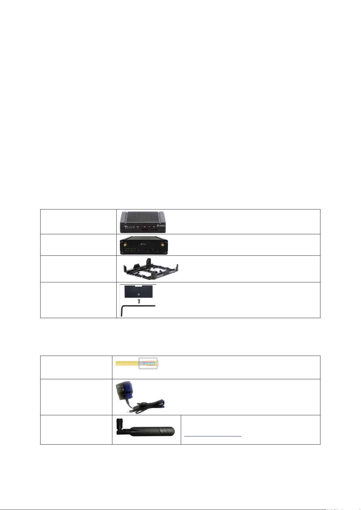
2.11.1 Standard components
1 x GW1000 Series router
with carrier
1 x GW1000M Se ri e s router
1 x plastic carrier
1 x lockable SIM cover
Table 3: GW1000 Series router standard components
2.11.2 Optional components
Ethernet cable. RJ45
connector at both ends.
Power supply unit.
Right angle antenna for
3G or 4G network.
_______________________________________________________________________________________________________
© Virtual Access 2018
GW1000 Series User Manual
Issue: 2.3 Page 18 of 463
Virtual Access supplies a wide range of antennas for
3G or 4G networks. Please visit our website:
www.virtualaccess.com
or contact Virtual Access for
Page 19

_______________________________________________________________________________________________________
2: GW1000 and GW1000M Series router hardware
Right angle or straight
stubby antenna for WiFi
connection
1 x fused automotive
cable
1 x non-fused automotive
cable
Table 4: GW1000 Series router optional components
2.12 Inserting a SIM card
1. Ensure the unit is powered off.
2. Hold the SIM 1 card with the chip side facing down and the cut cor ner front left.
3. Gently push the SIM card into SIM slot 1 until it clicks in.
4. If using SIM 2 then hold the SIM with the cut corner fr ont right
Virtual Access supplies a wide range of antennas for WiFi. Please
visit our website: www.virtualaccess.com
for more information.
or contact Virtual Access
5. Gently push the SIM card into SIM slot 2 until it clicks in.
2.13 Connecting the SIM lock
Connect the SIM lock using the Allen key provided.
2.14 Connecting cables
Connect one end of the Ethernet cable into port A and the other end to your PC or
switch. For information on connecting cables for a vehicle installation, read chapter 4,
‘Installing a router into a vehicle’.
2.15 Connecting the antenna
If you are connecting only one antenna, screw the antenna into the MAIN SMA
connector.
If you are using two antennas, screw the main antenna into the MAIN SMA connect or
and the secondary antenna into the AUX SMA connec tor.
2.16 Powering up
The router takes approximately 2 minutes to boot up. During this time, the PWR/CONFIG
LED flashes in a double flash pattern – 2 quick fashes followed b y a pause.
Other LEDs display different diagnostic patterns during boot up.
_______________________________________________________________________________________________________
© Virtual Access 2018
GW1000 Series User Manual
Issue: 2.3 Page 19 of 463
Page 20

_______________________________________________________________________________________________________
behaviour
normal reset.
Booting is complete when the PWR/CONFIG LED stops double flashing and s ta ys solid or
flashing steady, indicating the particular running configuration is loaded. Read the
chapter ‘GW1000 LED behaviour’, for PWR/CONFIG LED states.
2.17 Reset button
The reset button is used to request a system reset.
When you press the reset button the PWR/CONFIG LED will display different patterns
depending on how long you press the button. The flashing patterns will be different for
the 2 flashing phases indicated below. The length of time yo u hold the reset button will
determine the router behaviour.
2: GW1000 and GW1000M Series router hardware
Press duration PWR/CONFIG LED
0-3 seconds Solid on Normal reset to running config. No special
Between 3 and 15 seconds Flashing fast Releasing between 3-15 seconds switches
Between 15 and 20 seconds Solid on Releasing between 15-20 seconds performs
Between 20 seconds and 30 seconds Flashing slowly Releasing between 20-30 seconds reboots
Over 30 seconds Solid on Releasing after 30 seconds performs a
2.17.1 Recovery mode
Recovery mode is a fail-safe mode where the router can load a default configuration
from the routers firmware. If your router goes into recovery mode, all config files are
kept intact. After the next reboot, the router will revert to the previous config file.
You can use recovery mode to manipulate the config files, but should only be used if all
other configs files are corrupt. If your router has entered recovery mode, contact you r
local reseller for access information.
Router behaviour on depress
LED activity.
the router back to factory configuratio n.
a normal reset to running config.
the router in recovery mode.
Table 5: GW1000 Series router reset behaviour
_______________________________________________________________________________________________________
© Virtual Access 2018
GW1000 Series User Manual
Issue: 2.3 Page 20 of 463
Page 21
_______________________________________________________________________________________________________
3: GW1000 and GW1000M Series LED behaviour
3 GW1000 and GW1000M Series LED behaviour
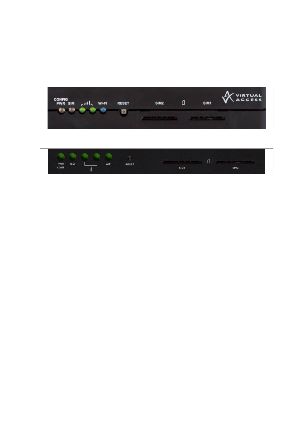
3.1 Main LED behaviour
There are five LEDs on the GW1000 and GW1000M Series rout e r
Figure 7: LEDs on the GW1000 Series router
Figure 8: LEDs on the GW1000M Series router
The possible LED states are:
• Off
• Flashing slowing (2 flashes per second)
• Flashing quickly (5 flashes per second)
• Double flash (2 quick flashes then a pause)
• On
_______________________________________________________________________________________________________
© Virtual Access 2018
GW1000 Series User Manual
Issue: 2.3 Page 21 of 463
Page 22

_______________________________________________________________________________________________________
Double flash
Unit is booting from power on.
Off
Not selected or SIM not inserted.
Both LEDs off
Not connected or signal strength <= -113dBm.
Right LED off
Off
WiFi not enabled.
3: GW1000 and GW1000M Series LED behaviour
The following table describes the possible LED behaviours and meanings on the GW1000
and GW1000M Series router.
The router takes approximate ly 2 minutes to boot up. During this time,
the power LED flashes.
Booting
Off No power/boot loader does not exist.
Other LEDs display different diagnos tic p atter ns dur ing boot up.
Booting is complete when the power LED stops flashing and stays on
steady.
PWR/CONFIG
LED
SIM LEDs
Signal LEDs
WiFi LEDs
Flashing slowly Unit is in recovery mode.
Flashing quickly Unit is in factory configuration.
Solid on Unit has completed booting up process and is in either config 1 or
config2.
Flashing SIM selected and data connection is being estab li s he d .
Solid on SIM selected and registered on the network.
Left LED on
Left LED off
Right LED on
Both LEDs on Connected and signal strength >-69dBm.
Flashing Data activity on WiFi interface.
Solid on WiFi is enabled.
Connected and signal strength <= -89dBm.
Connected and signal strength between -89dBm and -69dBm.
Table 6: LED behaviour and descriptions
Note: when a data connection does not exist, none of the signal LEDs will light
regardless of signal strength.
3.2 GW1000 and GW1000M Series Ethernet port LED behaviour
The Ethernet port has two physical LEDs, one is green and one is amber. When looking
at the port the green LED is on the left and is the only active LED.
Figure 9: Ethernet LED on the rear of the GW1000 Series router
Off No physical Ethernet link detected
Link LED
(green)
_______________________________________________________________________________________________________
© Virtual Access 2018
GW1000 Series User Manual
Issue: 2.3 Page 22 of 463
On Physical Ether ne t link d e tected
Flashing Data is being transmitted/ received over the link
Table 7: The Ethernet LEDs activity descriptions
Page 23
_______________________________________________________________________________________________________
4: Installing a router into a vehicle
4 Installing a router into a vehicle
The type of cable you need depends on your application and vehicle. You will have
received eit h er a fu sed or non-fused power cable for the installation.
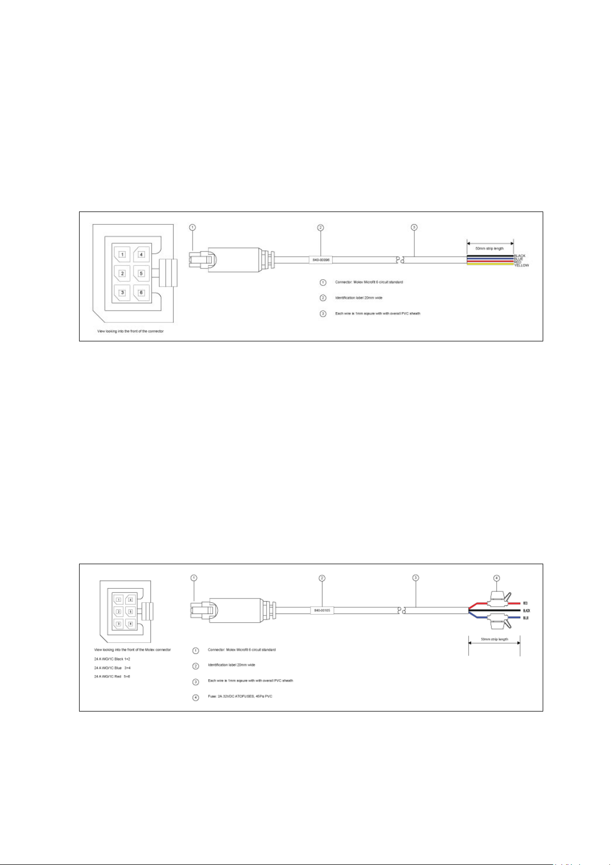
4.1 Installing a router into a vehicle using a non-fused power cable
Install the router using the vehic le installation power cab le 840-00076 provided.
Figure 10: 840-00096 3 core power cable
• Link pins 1 and 2 and bring out on a BLACK ground wire.
• Wire pin 3 and bring out on a BLUE wire to a 12V switched vehicle ignition wire.
• Link pins 5 and 6 and bring and bring out on a RED 12v permanent wire.
• Wire pin 4 and bring out on a YELLOW voltage sense wire.
• Plug the 6 pin connector into the router.
Note: requires 5 amp fuse in series with red and blue wires.
4.2 Installing a ro uter into a veh icle using a fused power cable
Install the router using the vehic le installation power cab le 840-00105 provided.
Figure 11: 840-00105 3 core power cable
_______________________________________________________________________________________________________
© Virtual Access 2018
GW1000 Series User Manual
Issue: 2.3 Page 23 of 463
Page 24

_______________________________________________________________________________________________________
(1)
Connector: Molex Microfit 6circuit standard
(2)
Label 20mm wide
(3)
Each wire is 1.0mm square, with overall PVC sheath
(4)
Fuse
Note:
Requires 5 amp fuse in series with red and blue wires
4: Installing a router into a vehicle
Table 8: Power cable descriptions
• Connect the BLACK wire to a ground wire.
• Connect the BLUE wire to a 12V switched vehicle ignition wire.
• Connect the RED wire to a 12V permanent wire.
Plug the 6 pin connector into the router.
_______________________________________________________________________________________________________
© Virtual Access 2018
GW1000 Series User Manual
Issue: 2.3 Page 24 of 463
Page 25

_______________________________________________________________________________________________________
5: Factory configuration extraction from SIM card
5 Factory configuration extract ion from SIM c a rd
Virtual Access routers have a feature to update the factory configuration from a SIM
card. This allows you to change the factory configuration of a router when installing the
SIM.
1. Make sure the SIM card you are inserting has the required configuration written on it.
2. Ensure the router is p owered off.
3. Hold the SIM 1 card with the chip side facing down and the cut corner front left.
4. Gently push the SIM card into SIM slot 1 until it clicks in.
5. Power up the router.
Depending on the model, the power LED and/or the configuration LED flash as usual.
The SIM LED starts flashing . This indicates the application responsible for 3G and
configuration extraction management is running. It also means the update of the
configuration is happening.
When the update is finished, depending on the model, the power LED and/or the
configuration LED blink a lternatively and very fast for 20 seconds.
Note: factory configuration extraction is only supporte d on mobile modules that support
phone book operations.
_______________________________________________________________________________________________________
© Virtual Access 2018
GW1000 Series User Manual
Issue: 2.3 Page 25 of 463
Page 26
_______________________________________________________________________________________________________
Package
Sections
system
main
cert
PC IP address
192.168.100.100
6: Accessing the router
6 Accessing the router
Access the router through the web interface or by using SSH. By default, Telnet is
disabled.
6.1 Configuration packages used
dropbear dropbear
uhttpd main
6.2 Accessing the router over Eth ernet using the web interface
DHCP is disabled by default, so if you do not receive an IP addre ss via DHCP, assign a
static IP to the PC that will be connected to the router.
Network mask 255.255.255.0
Default gateway 192.168.100.1
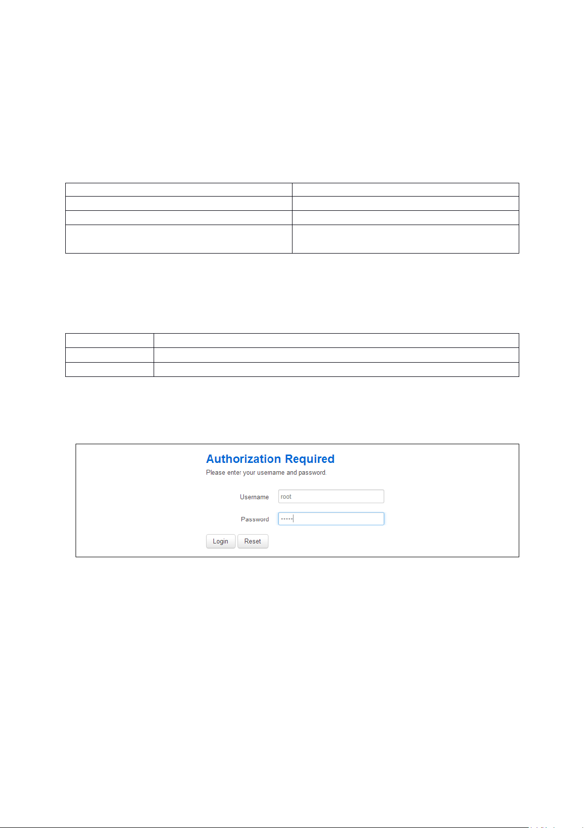
Assuming that the PC is connected to Port A on the router, in your interne t browser, type
in the default local IP address 192.168.100.1, and press Enter. The Authorization page
appears.
Figure 12: The login page
The password may vary depending on the factory configuration the router has been
shipped with. The default settings are shown below. The username and password are
case sensitive.
In the username field, type root.
In the Password field, type admin.
Click Login. The Status page appears.
_______________________________________________________________________________________________________
© Virtual Access 2018
GW1000 Series User Manual
Issue: 2.3 Page 26 of 463
Page 27

_______________________________________________________________________________________________________
6.3 Accessing the router over Eth ernet using a n SSH client
You can also access the router over Ethernet, using Secure Shell (SSH) and optionally
over Telnet.
To access CLI over Ethernet start an SSH client and connect to the router’s management
IP address, on port 22: 192.168.100.1/24.
On the first connection, you may be asked to confirm that you trust the host.
6: Accessing the router
Figure 13: Confirming trust of the routers public key over SSH
Figure 14: SSH CLI logon screen
In the SSH CLI logon screen, enter the default username and password.
Username: root
Password: admin
6.3.1 SCP (Secure Copy Protocol)
As part of accessing the router over SSH, you can also use SCP protocol. Use the same
user authentication credentials as for SSH access. You can use SCP protocol to securely,
manually transfer files from and to the router’s SCP server.
No dedicated SPC client is supported; select the SCP client software of your own choice.
_______________________________________________________________________________________________________
© Virtual Access 2018
GW1000 Series User Manual
Issue: 2.3 Page 27 of 463
Page 28
_______________________________________________________________________________________________________
Package
Sections
6.4 Accessing the router over Eth ernet using a Telnet clie n t
Telnet is disabled by default, when you enable Telnet, SS H is disabled.
To enable Teln et, en ter:
root@VA_router: ~# /etc/init.d/dropbear disable
root@VA_router: ~# reboot
To re-enable SSH, enter:
root@VA_router: ~# /etc/init.d/dropbear enable
root@VA_router: ~# reboot
Note: as SSH is enabled by default, initial connection to the router to enable Telnet
must be established over SSH.
6: Accessing the router
6.5 Configuring the password
6.5.1 Configuration packages used
system main
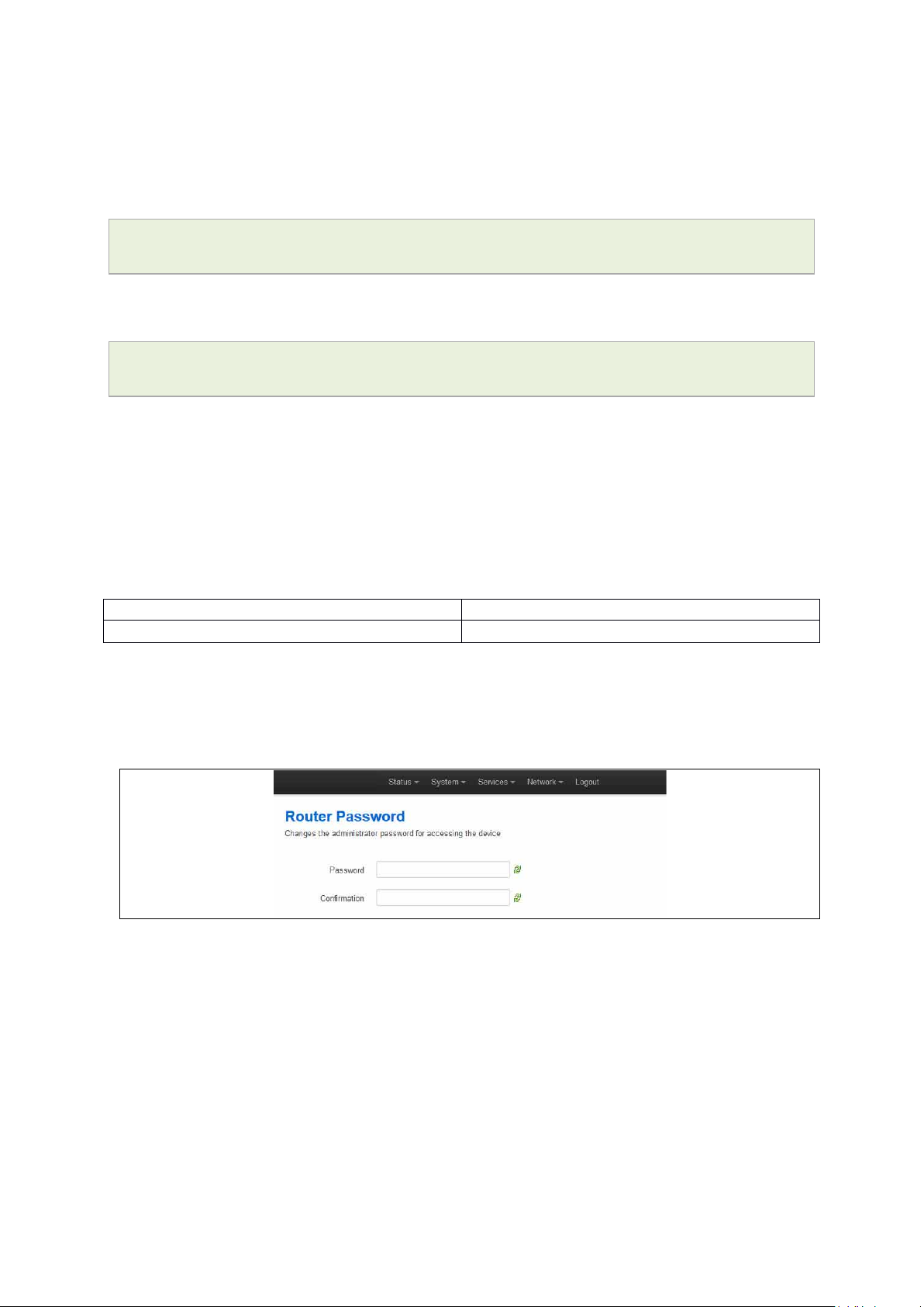
6.6 Configuring the password usi ng the web interface
To change your password, in the top menu click System -> Administration. The
Administration page appears.
Figure 15: The router password section
In the Router Password section, type your new password in the passw ord field and then
retype the password in the confirmation field.
Scroll down the page and click Save & Apply.
Note: the username ‘root’ cannot be changed.
_______________________________________________________________________________________________________
© Virtual Access 2018
GW1000 Series User Manual
Issue: 2.3 Page 28 of 463
Page 29

_______________________________________________________________________________________________________
Web Field/UCI/Package Option
Description
6: Accessing the router
Web: Password
UCI: system.main.password
Opt: password
Defines the root password. The password is displ ay ed encrypte d
via the CLI using the ‘hashpassword’ option.
UCI: system.main.hashpasswo rd
Opt: hashpassword
6.7 Configuring the password using UCI
The root password is displayed encrypted via the CLI using the hashpassword option.
root@VA_router:~# uci show system
system.main=system
system.main.hostname=VA_router
system.main.hashpassword=$1$jRX/x8A/$U5kLCMpi9dcahRhOl7eZV1
If you are changing the password using UCI, enter the new password in plain text using
the password option.
root@VA_router:~# uci system.main.password=newpassword
root@VA_router:~# uci commit
The new password will take effect after reboot and will now be displayed in encrypted
format via the hashpassword option.
6.8 Configuring the password usi ng package options
The root password is displayed encrypted via the CLI using the hashpassword option.
root@VA_router:~# uci export system
package system
config system 'main'
option hostname 'VA_router'
option hashpassword '$1$wRYYiJOz$EeHN.GQcxXhRgNPVbqxVw
If you are changing the password using UCI, enter the new password in plain text using
the password option.
package system
config system 'main'
option hostname 'VA_router'
option hashpassword '$1$wRYYiJOz$EeHN.GQcxXhRgNPVbqxVw
option password ‘newpassword’
The new password will take effect after reboot and will now be displayed in encrypted
format via the hashpassword option.
_______________________________________________________________________________________________________
© Virtual Access 2018
GW1000 Series User Manual
Issue: 2.3 Page 29 of 463
Page 30

_______________________________________________________________________________________________________
6.9 Accessing the device using RADIUS authentication
You can configure R ADIUS a ut hentication to acce ss the router over SSH, web or local
console interface.
package system
config system 'main'
option hostname 'VirtualAccess'
option timezone 'UTC'
config pam_auth
option enabled 'yes'
option pamservice 'login'
option pammodule 'auth'
6: Accessing the router
option pamcontrol 'sufficient'
option type 'radius'
option servers '192.168.0.1:3333|test|20 192.168.2.5|secret|10'
config pam_auth
option enabled 'yes'
option pamservice 'sshd'
option pammodule 'auth'
option pamcontrol 'sufficient' it checks package
management_users
option type 'radius'
option servers '192.168.0.1:3333|test|20 192.168.2.5|secret|10'
config 'pam_auth'
option enabled 'yes'
option pamservice 'luci"
option pammodule 'auth'
option pamcontrol 'sufficient'
option type 'radius'
servers '192.168.0.1:3333|test|20 192.168.2.5|secret|10'
_______________________________________________________________________________________________________
© Virtual Access 2018
GW1000 Series User Manual
Issue: 2.3 Page 30 of 463
Page 31

_______________________________________________________________________________________________________
UCI/Package Option
Description
configuration section.
configuration section.
luci
User connecting over web.
management_users)
the router.
Opt: pammodule
6: Accessing the router
UCI: system.@pam_auth[0].enabled=yes
Opt: enabled
UCI: system.@pam_auth[0].pamse rv ic e
Opt: pamservice
UCI: system.@pam_auth[0].pamcontrol
Opt: pamcontrol
UCI:
system.@pam_auth[0].pammodule.auth
Enables and disables RADIUS configuration sections.
yes
no Disables following RADIUS
Selects the method which users should be authentic ate d by.
login User connecting over console cable.
sshd User connecting over SSH.
Specifies authentication behav i o ur after authentication fails or
connection to RADIUS server is broken.
Sufficient
Required If either authentication fails or
[success=done
new_authtok_reqd=done
authinfo_unavail=ignore
default=die]
Enables user authentication.
Enables following RADIUS
First authenticates against remote
RADIUS if password authe nti c ation
fails then it tries local database
(user defined in package
RADIUS server is not reachable
then user is not allowed to access
Local database is only checked if
RADIUS server is not reachable.
UCI: system.@pam_auth[0].type.radius
Opt: type
UCI: system.@pam_auth[0].servers
Opt: servers
Specifies the authentication metho d.
Specifies the RADIUS server or multiple servers along with port
number and password. The example below explains the syntax.
192.168.0.1:3333|test|20 192.168.2.5|secret|10
Table 9: Information table for RADIUS authentication
6.10 Accessing the device using TACACS+ authentication
TACACS+ authentication can be configured for accessing the router over SSH, web or
local console interface.
package system
config system 'main'
option hostname 'VirtualAccess'
option timezone 'UTC'
config pam_auth
option enabled 'yes'
option pamservice 'sshd'
_______________________________________________________________________________________________________
© Virtual Access 2018
GW1000 Series User Manual
Issue: 2.3 Page 31 of 463
Page 32

_______________________________________________________________________________________________________
6: Accessing the router
option pammodule 'auth'
option pamcontrol 'sufficient'
option type 'tacplus'
option servers '192.168.0.1:49|secret'
config pam_auth
option enabled 'yes'
option pamservice 'sshd'
option pammodule 'account'
option pamcontrol 'sufficient'
option type 'tacplus'
option servers '192.168.0.1:49|secret'
option args 'service=ppp'
config pam_auth
option enabled 'yes'
option pamservice 'sshd'
option pammodule 'session'
option pamcontrol 'sufficient'
option type 'tacplus'
option servers '192.168.0.1:49|secret'
option args 'service=ppp'
config pam_auth
option enabled 'yes'
option pamservice 'luci'
option pammodule 'auth'
option pamcontrol 'sufficient'
option type 'tacplus'
option servers '192.168.0.1:49|secret'
config pam_auth
option enabled 'yes'
option pamservice 'luci'
option pammodule 'account'
option pamcontrol 'sufficient'
option type 'tacplus'
_______________________________________________________________________________________________________
© Virtual Access 2018
GW1000 Series User Manual
Issue: 2.3 Page 32 of 463
Page 33

_______________________________________________________________________________________________________
6: Accessing the router
option servers '192.168.0.1:49|secret'
option args 'service=ppp'
config pam_auth
option enabled 'yes'
option pamservice 'luci'
option pammodule 'session'
option pamcontrol 'sufficient'
option type 'tacplus'
option servers '192.168.0.1:49|secret'
option args 'service=ppp'
config pam_auth
option enabled 'yes'
option pamservice 'login'
option pammodule 'auth'
option pamcontrol 'sufficient'
option type 'tacplus'
option servers '192.168.0.1:49|secret'
config pam_auth
option enabled 'yes'
option pamservice 'login'
option pammodule 'account'
option pamcontrol 'sufficient'
option type 'tacplus'
option servers '192.168.0.1:49|secret'
option args 'service=ppp'
config pam_auth
option enabled 'yes'
option pamservice 'login'
option pammodule 'session'
option pamcontrol 'sufficient'
option type 'tacplus'
option servers '192.168.0.1:49|secret'
option args 'service=ppp'
_______________________________________________________________________________________________________
© Virtual Access 2018
GW1000 Series User Manual
Issue: 2.3 Page 33 of 463
Page 34

_______________________________________________________________________________________________________
UCI/Package Option
Description
configuration section.
configuration section.
luci
User connecting over web.
management_users)
Opt: type
192.168.0.1:49|secret '
Opt: args
6: Accessing the router
UCI: system.@pam_auth[0].enabled=yes
Opt: enabled
UCI: system.@pam_auth[0].pamse rv ic e
Opt: pamservice
UCI: system.@pam_auth[0].pamco ntro l
Opt: pamcontrol
UCI:
system.@pam_auth[0].pammodule.auth
Opt: pammodule
system.@pam_auth[0].type=tacplus
Enables and disables TACACS config uratio n sec tions.
yes
Enables following TACACS
no Disables following TACACS
Selects the method which users should be authentic ate d by.
login User connecting over console cable.
sshd User connecting over SSH.
Specifies authentication behav i o ur after authentication fails or
connection to TACACS server is broken.
Sufficient
First authenticates against
remote TACACS if pass word
authentication fails then it
tries local database (user
defined in package
Required If either authentication fails
or TACACS server is not
reachable then user is not
allowed to access the router.
[success=done
new_authtok_reqd=done
authinfo_unavail=ignore
Local database is only
checked if TACACS server is
not reachable.
default=die]
Selects which TACACS module this part of configur ation relates
to.
auth auth module provides the actual
authentication and sets credentials
account account module checks to make sure
that access is allowed for the user
session session module performs additional
tasks which are needed to allow
access
Specifies the authentication metho d.
UCI: system.@pam_auth[0].servers
Opt: servers
UCI:
system.@pam_auth[1].args=service=ppp
6.11 SSH
SSH allows you to access remote machines over text-based shell sessions. SSH uses
public key cryptography to create a secure connection. These connections allow y ou to
issue commands remotely via a command line.
_______________________________________________________________________________________________________
© Virtual Access 2018
GW1000 Series User Manual
Issue: 2.3 Page 34 of 463
Specifies the TACACS servers along with port number and
password. The examp le below explains the syntax .
Additional arguments to pass to TACACS serer.
Table7: Information table for TACACS auth entication
Page 35

_______________________________________________________________________________________________________
Package
Sections
The router uses a package called Dropbear to configure the SSH server on the box. You
can configure Dropb ear via the web interface or t hrough an SSH connection by editing
the file stored on: /etc/config_name/dropbear.
6.11.1 Configuration packages used
dropbear dropbear
6.11.2 SSH access using the web interface
In the top menu, click System -> Administration. The Administration page appears.
Scroll down to the SSH Access section.
6: Accessing the router
Figure 16: The SSH access section
_______________________________________________________________________________________________________
© Virtual Access 2018
GW1000 Series User Manual
Issue: 2.3 Page 35 of 463
Page 36

_______________________________________________________________________________________________________
Web Field/UCI/Packag e Optio n
Description
(unspecified)
listens on all interfaces.
Range
0-65535
Opt: PasswordAuth
0
Disabled.
Opt: RootPasswordAuth
1
Enabled.
1
Enabled.
30
30 seconds.
Range
10
6: Accessing the router
Basic settings
Web: Interface
UCI: dropbear.@dropbear[0].Interface
Opt: interface
Listens only on the selected interface. If uns pec ified is checked,
listens on all interfaces. All configured interfaces will be displayed
via the web GUI.
Range Configured interface names .
Web: Port
UCI: dropbear.@dropbear[0].Po rt
Specifies the listening port of the Dropb e ar ins tanc e .
22
Opt: port
Web: Password authentication
If enabled, allows SSH password authentication.
UCI:
dropbear.@dropbear[0].PasswordAuth
1 Enabled.
Web: Allow root logins with password
UCI:
dropbear.@dropbear[0].RootPasswordAuth
Web: Gateway ports
UCI:
dropbear.@dropbear[0].GatewayPorts
Opt: GatewayPorts
Web: Idle Session Timeout
UCI: dropbear.@dropbear[0].IdleTimeout
Opt: IdleTimeout
Web: n/a
UCI: dropbear.@dropbear[0]. BannerFile
Opt: BannerFile
Web: n/a
UCI:
dropbear.@dropbear[0].MaxLoginAttempts
Opt: MaxLoginAttempts
Table 10: Information table for SSH access settings
Allows the root user to login with password.
0 Disabled.
Allows remote hosts to connect to local SSH forwarded ports.
0 Disabled.
Defines the idle period where remote session will be closed after
the allocated number of seconds of inactivity .
Range
Defines a banner file to be displayed during logi n.
/etc/banner
Specifies maximum login failure s bef or e sessi o n ter minate s .
0-infinite
6.12 Package dropbear using UCI
root@VA_router:~# uci show dropbear
dropbear.@dropbear[0]=dropbear
dropbear.@dropbear[0].PasswordAuth=on
dropbear.@dropbear[0].RootPasswordAuth=on
dropbear.@dropbear[0].GatewayPorts=0
dropbear.@dropbear[0].IdleTimeout=30
dropbear.@dropbear[0].Port=22
dropbear.@dropbear[0].MaxLoginAttempts=3
Package dropbear using package options
_______________________________________________________________________________________________________
© Virtual Access 2018
GW1000 Series User Manual
Issue: 2.3 Page 36 of 463
Page 37
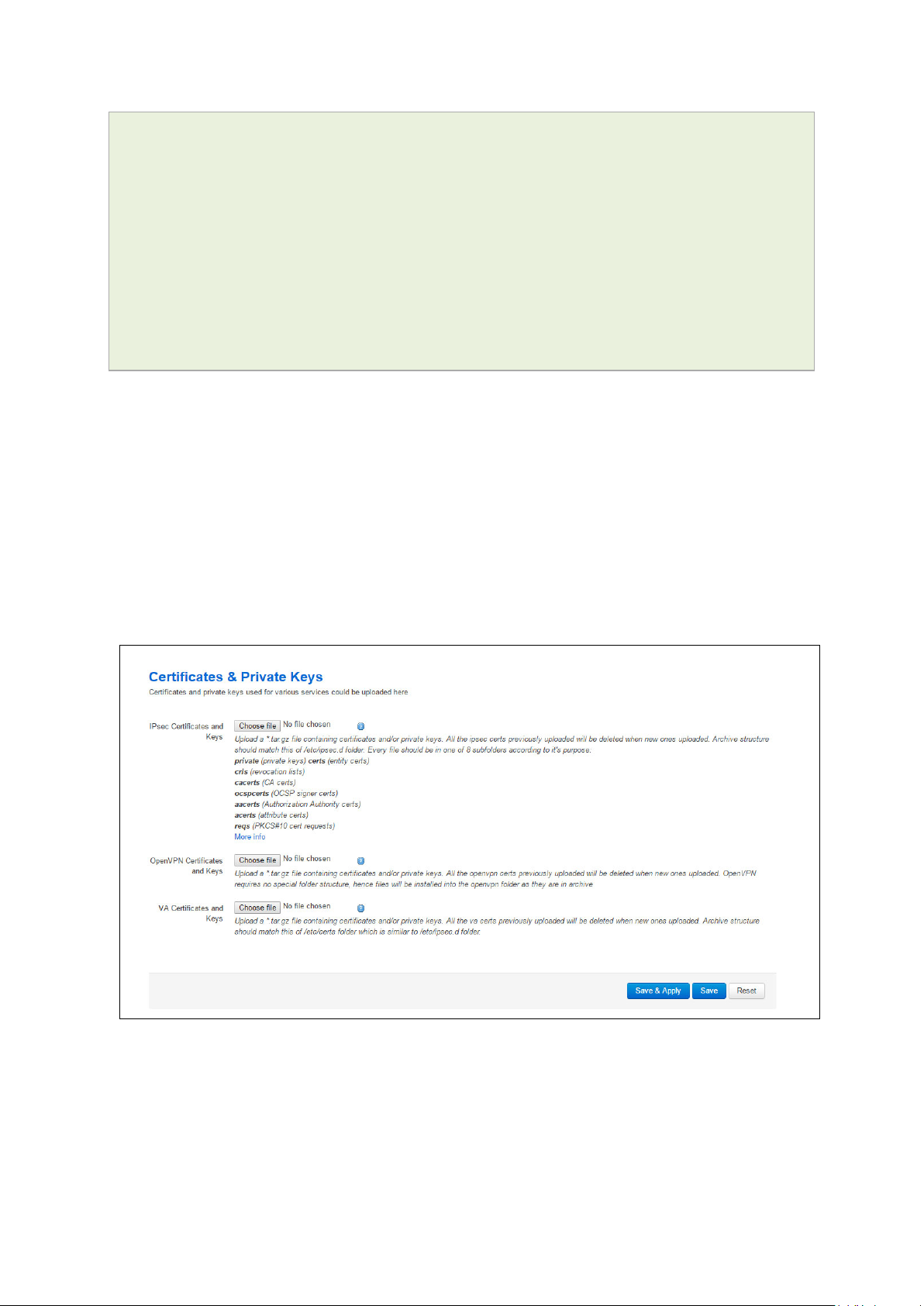
_______________________________________________________________________________________________________
root@VA_router:~# uci export dropbear
package dropbear
config dropbear'
option PasswordAuth 'on'
option RootPasswordAuth 'on'
option Port '22'
option GatewayPorts ‘0’
option IdleTimeout ‘30’
option MaxLoginAttempts '3'
6.13 Certs and private keys
Certificates are used to prove ownership of a public key. They contain information about
the key, its owner’s ID, and the digital signature of a n individual that has verified the
content of the certificate.
6: Accessing the router
In asymmetric cryptography, public keys are announced to the public, and a different
private key is kept by the receiver. The public key is used to encrypt the message, and
the private key is used to decrypt it.
To access certs and private keys, in the top menu, click System -> Ad ministration.
The Administration page appears. Scroll down to the Certs & Private Keys section.
Figure 17: The certificates & private keys section
This section allows you to upload any certificates and ke ys that you may have stored.
There is support for IPSec, OpenVPN and VA certificates and keys.
If you have generated your own SSH public keys, you can input them in the SSH Keys
section, for SSH public key authentication.
_______________________________________________________________________________________________________
© Virtual Access 2018
GW1000 Series User Manual
Issue: 2.3 Page 37 of 463
Page 38

_______________________________________________________________________________________________________
Package
Sections
main
Figure 18: The SSH-keys box
6.14 Configuring a router’s web server
The router’s web server is configured in package uhttpd. This file defines the behaviour
of the server and default values for certificates generated for SSL operation. uhttpd
supports multiple instances, that is, multiple listen ports, each with its own document
root and other features, as well as cgi and lua. There are two sections defined:
Main: this uHTTPd section contains general server settings.
Cert: this section defines the default values for SSL certificates.
6: Accessing the router
6.14.1 Configuration packages used
uhttpd
To configure the router’s HTTP server parameters, in the top menu, select Services ->
HTTP Server. The HTTP Server page has two sections.
Main Settings Server configurations
Certificate Settings SSL certificates.
cert
_______________________________________________________________________________________________________
© Virtual Access 2018
GW1000 Series User Manual
Issue: 2.3 Page 38 of 463
Page 39

_______________________________________________________________________________________________________
Web Field/UCI/Packag e Optio n
Description
interfaces.
[::]:443
Range
IP address an d/or port
Range
6.14.2 Main settings
6: Accessing the router
Web: Listen Address and Port
UCI: uhttpd.main.listen_http
Opt: list listen_http
Web: Secure Listen Address and Port
UCI: uhttpd.main.listen_https
Opt: list listen_https
Web: Home path
UCI: uhttpd.main.home
Opt: home
Web: Cert file
UCI: uhttpd.main.cert
Opt: cert
Web: Key file
UCI: uhttpd.main.key
Opt: key
Figure 19: HTTP server settings
Specifies the ports and addresses to listen on for plain HTTP
access. If only a port number is given, the server will attempt to
serve both IPv4 and IPv6 requests.
0.0.0.0:80 Bind at port 80 only on IPv4
[::]:80 Bind at port 80 only on IPv6
interfaces
Range IP address an d/or port
Specifies the ports and address to listen on for encrypte d HTTPS
access. The format is the same as listen_http.
0.0.0.0:443 Bind at port 443 only
Defines the server document root.
/www
Range
ASN.1/DER certificate used to serve HTTPS connections. If no
listen_https options are given the key options are ignored.
/etc/uhttpd.crt
ASN.1/DER private key used to serve HTTPS connections . If no
listen_https options are given the key options are ignored.
/etc/uhttpd.key
Range
_______________________________________________________________________________________________________
© Virtual Access 2018
GW1000 Series User Manual
Issue: 2.3 Page 39 of 463
Page 40

_______________________________________________________________________________________________________
/cgi-bin
Range
/usr/lib/lua/luci/sgi/uhttpd.lua
Range
Range
OpenWrt
/etc/http.conf
Range
Range
0
Disabled.
6: Accessing the router
Web: CGI profile
UCI: uhttpd.main.cgi_pref ix
Opt: cgi_prefix
Web: N/A
UCI: uhttpd.main.lua_prefi x
Opt: lua_prefix
Web: N/A
UCI: uhttpd.main.lua_handler
Opt: lua_handler
Web: Script timeout
UCI: uhttpd.main.script_time out
Opt: script_timeout
Web: Network timeout
UCI: uhttpd.main.network_ timeo ut
Opt: network_timeout
Defines the prefix for CGI scripts, relative to the document root.
CGI support is disabled if this option is missing .
Range
Defines the prefix for dispatching reque s ts to the embedd ed lua
interpreter, relative to the document roo t. Lua s uppor t is
disabled if this option is missing.
/luci
Specifies the lua handler script used to initia lis e the lua runtime
on server start.
Range
Sets the maximum wait time for CGI or lua requests in seconds.
Requested executables are terminated if no output w as
generated.
60
Maximum wait time for network activity. Requested executables
are terminated and connection is shut down if no networ k activity
occured for the specified number of seconds.
30
Web: N/A
UCI: uhttpd.main.realm
Opt: realm
Web: N/A
UCI: uhttpd.main.config
Opt: config
Web: N/A
UCI: uhttpd.main.index_page
Opt: index_page
Web: N/A
UCI: httpd.main.error_pag e
Opt: error_page
Web: N/A
UCI: uhttpd.main.no_symlinks
Opt: no_symlinks
Web: N/A
UCI: uhttpd.main.no_dirlists
Opt: no_symlinks
Defines basic authentication realm w he n pro mpting the client f or
credentials (HTTP 400).
Range
Config file in Busybox httpd format for additional se tti ng s .
Currently only used to specify basic auth ar e as.
Index file to use for directories, for examp le , add index.php when
using php.
Virtual URL of file of CGI script to handle 404 requests. Must
begin with ‘/’ (forward slash).
Range
Does not follow symbolic links if enabled .
0 Disabled.
1 Enabled.
Does not generate directory listings if enabled.
1 Enabled.
_______________________________________________________________________________________________________
© Virtual Access 2018
GW1000 Series User Manual
Issue: 2.3 Page 40 of 463
Page 41

_______________________________________________________________________________________________________
0
Disabled.
6: Accessing the router
Web: rfc 1918 filter
UCI: uhttpd.main.rfc1918_f ilte r=1
Opt: rfc1918_filter
Table 11: Information table for http server basic settings
6.14.3 HTTP server using UCI
Multiple sections of the type uhttpd may exist. The init script will launch one webserver
instance per section.
A standard uhttpd configuration is shown below.
root@VA_router:~# uci show uhttpd
uhttpd.main=uhttpd
uhttpd.main.listen_http=0.0.0.0:80
uhttpd.main.listen_https=0.0.0.0:443
uhttpd.main.home=/www
uhttpd.main.rfc1918_filter=1
uhttpd.main.cert=/etc/uhttpd.crt
Enables option to reject requests from RFC191 8 IPs to pub lic
server IPs (DNS rebinding counter measur e ).
1 Enabled.
uhttpd.main.key=/etc/uhttpd.key
uhttpd.main.cgi_prefix=/cgi-bin
uhttpd.main.script_timeout=60
uhttpd.main.network_timeout=30
uhttpd.main.config=/etc/http.conf
HTTP server using package options
root@VA_router:~# uci export dropbear
config uhttpd 'main'
list listen_http '0.0.0.0:80'
list listen_https '0.0.0.0:443'
option home '/www'
option rfc1918_filter '1'
option cert '/etc/uhttpd.crt'
option key '/etc/uhttpd.key'
option cgi_prefix '/cgi-bin'
option script_timeout '60'
option network_timeout '30'
option config '/etc/http.conf'
_______________________________________________________________________________________________________
© Virtual Access 2018
GW1000 Series User Manual
Issue: 2.3 Page 41 of 463
Page 42
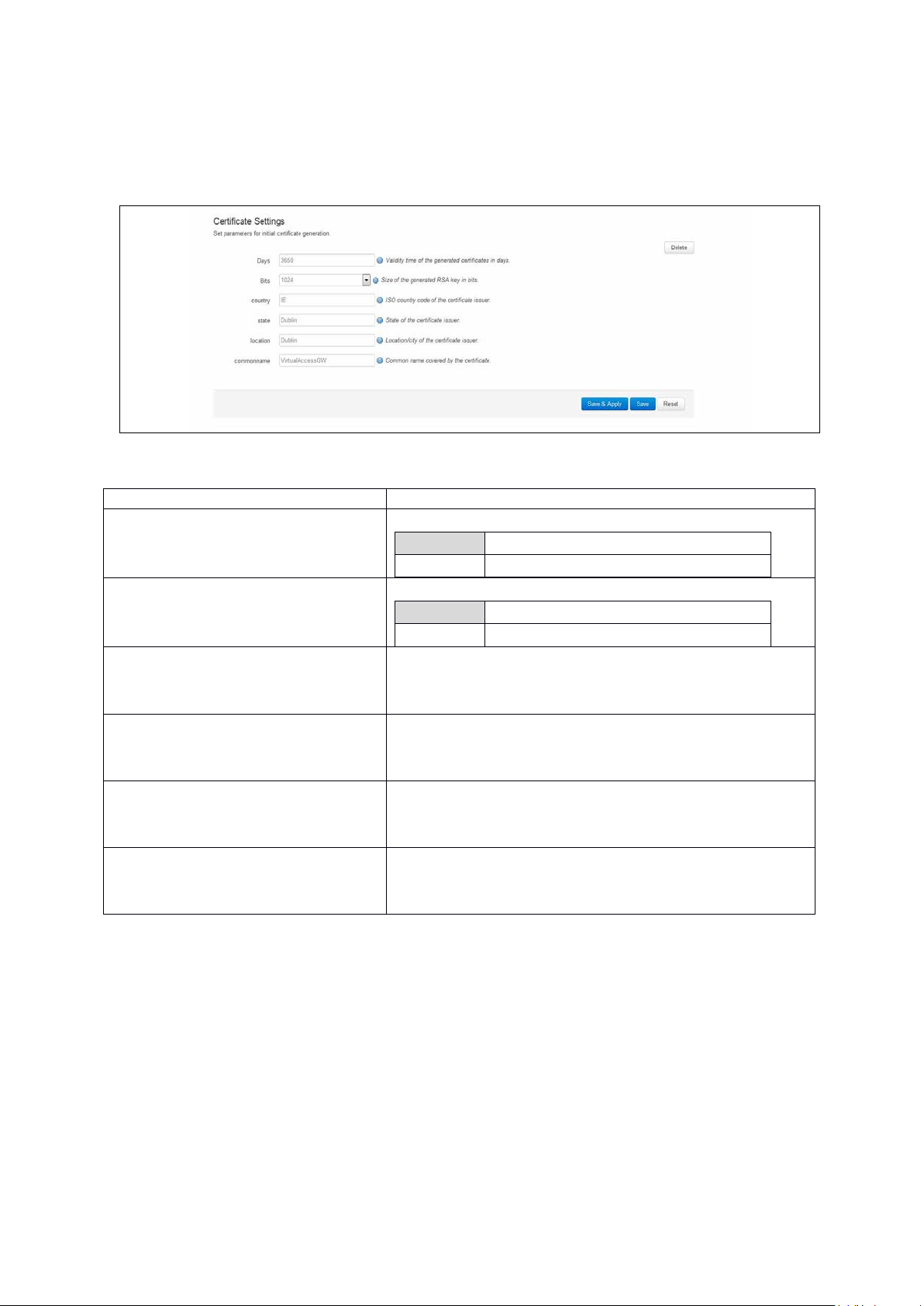
_______________________________________________________________________________________________________
Web Field/UCI/Packag e Optio n
Description
Range
6.14.4 HTTPs server certificate settings
To configure HTTPs server certificate settings, in the top menu, select Services ->
HTTP Server. Scroll down to the Certificate Settings section.
Figure 20: HTTP server certificate settings
6: Accessing the router
Web: Days
UCI: uhttpd.px5g.days
Opt: days
Web: Bits
UCI: uhttpd.px5g.bits
Opt: bits
Web: Country
UCI: uhttpd.px5g.country
Opt: country
Web: State
UCI: uhttpd.px5g.state
Opt: state
Web: Location
UCI: uhttpd.px5g.location
Opt: location
Web: Commonname
UCI: uhttpd.commonname
Opt: commonname
Table 12: Information table for HTTP server certificate settings
Validity time of the generated certifica te s in days.
730
Range
Size of the generated RSA key in bits.
1024
ISO code of the certificate issuer.
State of the certificate issuer.
Location or city of the certificate user.
Common name covered by the certificate. For the purposes of
secure Activation, this must be set to the serial number (Eth0
MAC address) of the device.
_______________________________________________________________________________________________________
© Virtual Access 2018
GW1000 Series User Manual
Issue: 2.3 Page 42 of 463
Page 43

_______________________________________________________________________________________________________
6.14.5 HTTPs server using U C I
root@VA_router:~# uci show uhttpd.px5g
uhttpd.px5g=cert
uhttpd.px5g.days=3650
uhttpd.px5g.bits=1024
uhttpd.px5g.country=IE
uhttpd.px5g.state=Dublin
uhttpd.px5g.location=Dublin
uhttpd.px5g.commonname=00E0C8000000
HTTPs server using package options
root@VA_router:~# uci export uhttpd
package uhttpdconfig 'cert' 'px5g'
option 'days' '3650'
6: Accessing the router
option 'bits' '1024'
option 'state' 'Dublin'
option 'location' 'Dublin'
option 'commonname' '00E0C8000000'
6.15 Basic authentication (httpd conf)
For backward compatibility reasons, uhttpd uses the file /etc/httpd.conf to define
authentication areas and the associated usernames and passwords. This configuration
file is not in UCI format.
Authentication realms are defined in the format prefix:username:password with one
entry and a line break.
Prefix is the URL part covered by the realm, for example, cgi-bin to request basic auth
for any CGI program.
Username specifies the username a client has to login with.
Password defines the secret password required to authenticate.
The password can be either in plain text format, MD5 encoded or in the form $p$user
where the user refers to an account in /etc/shadow or /etc/passwd.
If you use $p$… format, uhttpd will compare the client provided p a ss word against the
one stored in the shadow or passwd database.
_______________________________________________________________________________________________________
© Virtual Access 2018
GW1000 Series User Manual
Issue: 2.3 Page 43 of 463
Page 44

_______________________________________________________________________________________________________
luci
main
6.16 Securing uhttpd
By default, uhttpd binds to 0.0.0.0 which also includes the WAN port of your router. To
bind uhttpd to the LAN port only you have to change the listen_http and listen_https
options to your LAN IP address.
To get your current LAN IP address, enter:
uci get network.lan.ipaddr
Then modify the configuration appropr iate ly:
uci set uhttpd.main.listen_http='192.168.1.1:80'
uci set uhttpd.main.listen_https='192.168.1.1:443'
config 'uhttpd' 'main'
list listen_http 192.168.1.1:80
list listen_https 192.168.1.1:443
6: Accessing the router
6.17 Displaying custom information via login screen
The login screen, by default, shows the hostname of the router in addition to the
username and password prompt. However, the router can be configured to show some
other basic information if required using a UDS script.
Note: this can only be configured via the command line.
6.17.1 Configuration packages used
Package Sections
uds script
6.17.2 Configuring login screen custom information
The luci package option login_page_info_template is configured with the path to a
UDS script that would render the required information on the right side of the login page.
The following example shows how to display serial number and mobile signal strength.
Note: this can only be configured via the command line.
Figure 21: Example login screen displaying serial and signal strength
_______________________________________________________________________________________________________
© Virtual Access 2018
GW1000 Series User Manual
Issue: 2.3 Page 44 of 463
Page 45

_______________________________________________________________________________________________________
6.17.2.1 Login screen custom information using UCI
root@VA_router:~# uci show luci
luci.main=core
luci.main.login_page_info_template=/tmp/uds/sysauth_template
root@VA_router:~# uci show uds
uds.sysauth_template=script
uds.sysauth_template.enabled=1
uds.sysauth_template.exec_type=none
uds.sysauth_template.fname=sysauth_template.htm
uds.sysauth_template.type=none
uds.sysauth_template.text=Serial: <%=pcdata(luci.version.serial)%><br/> <%
local sig = luci.dispatcher.uci.cursor_state():get("mobile", "3g_1_1",
"sig_dbm") or -113 sig = tonumber(sig) local hue = (sig + 113) * 2 local
hue = math.min(math.max(hue, 0), 120) %> Signal strength: <h3
style="color:hsl(<%=hue%>, 90%, 50%); display:inline;"><%=sig%></h3> dBm
6: Accessing the router
6.17.2.2 Login screen custom information using package options
root@VA_router:~# uci export luci
package luci
config core ‘main’
option login_page_info_template ‘/tmp/uds/sysauth_template’
root@VA_router:~# uci export uds
package uds
config script 'sysauth_template'
option enabled '1'
option exec_type 'none'
option fname 'sysauth_template.htm'
option type 'none'
list text 'Serial: <%=pcdata(luci.version.serial)%><br/>'
list text '<% local sig =
luci.dispatcher.uci.cursor_state():get("mobile", "3g_1_1", "sig_dbm") or 113'
list text 'sig = tonumber(sig)'
list text 'local hue = (sig + 113) * 2'
list text 'local hue = math.min(math.max(hue, 0), 120) %>'
list text 'Signal strength: <h3 style="color:hsl(<%=hue%>, 90%,
50%); display:inline;"><%=sig%></h3> dBm
_______________________________________________________________________________________________________
© Virtual Access 2018
GW1000 Series User Manual
Issue: 2.3 Page 45 of 463
Page 46
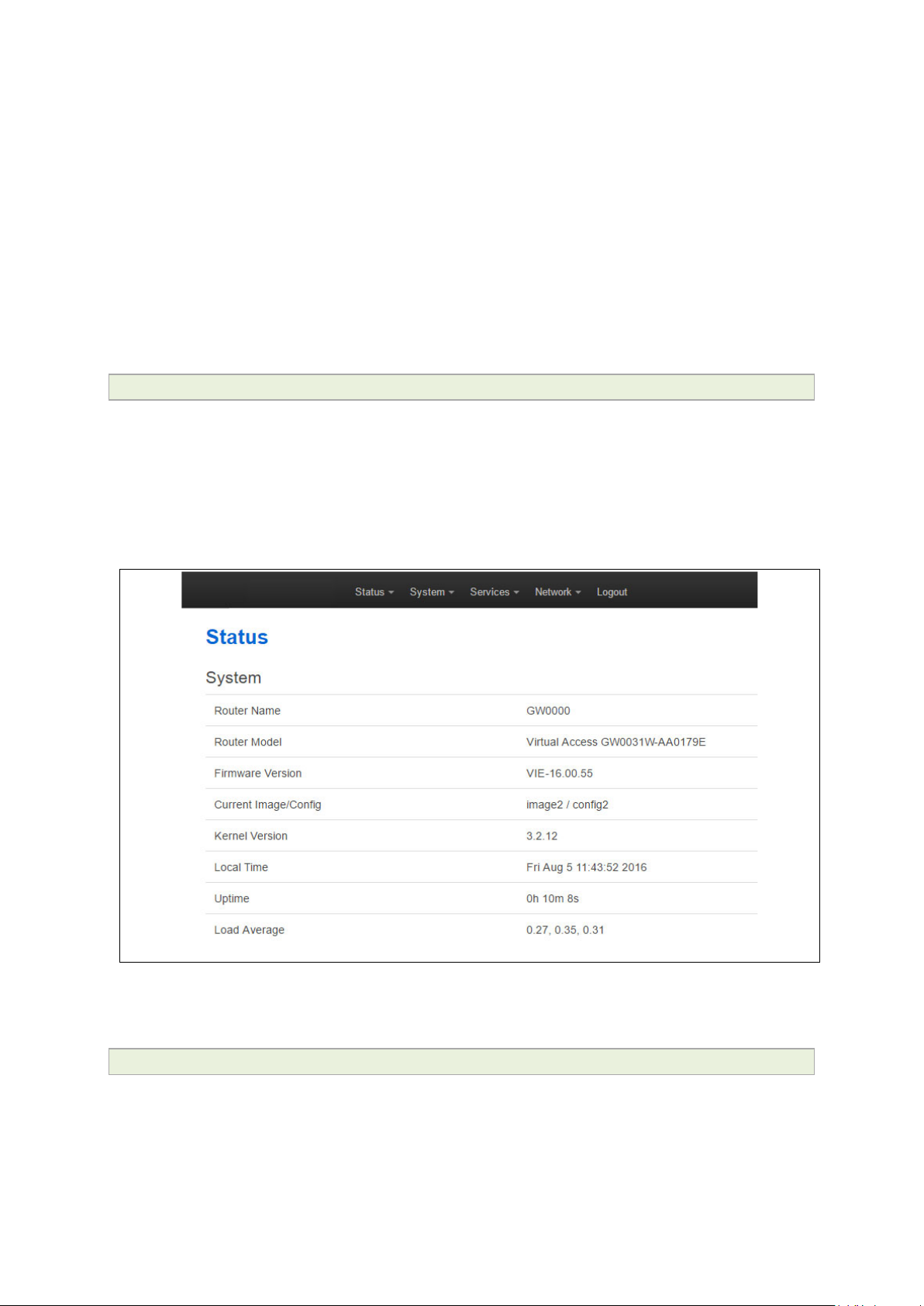
_______________________________________________________________________________________________________
7 Router file structure
This section describes the file structure and location of essential directories and files on
Virtual Access routers.
Throughout this document, we use information tables to show the different ways to
configure the router using the router’s we b interface and command line interface (CLI).
When showing examples of the command line interface we use the host name
‘VA_router’ to indicate the system prompt. For example, the table below displays what
the user should see when entering the command to show the current configuration in
use on the router:
root@VA_router:~# va_config.sh
7.1 System information
General information about software and configuration used by the router is displayed on
the Status page. To view the running configuration file status on the web interface, in
the top menu, select Status -> Overview. This page also appears immediately after
you have logged in.
7: Router file structure
Figure 22: Example of the status page
System information is also available from the CLI if you enter the following com mand:
root@VA_router:~# va_vars.sh
_______________________________________________________________________________________________________
© Virtual Access 2018
GW1000 Series User Manual
Issue: 2.3 Page 46 of 463
Page 47
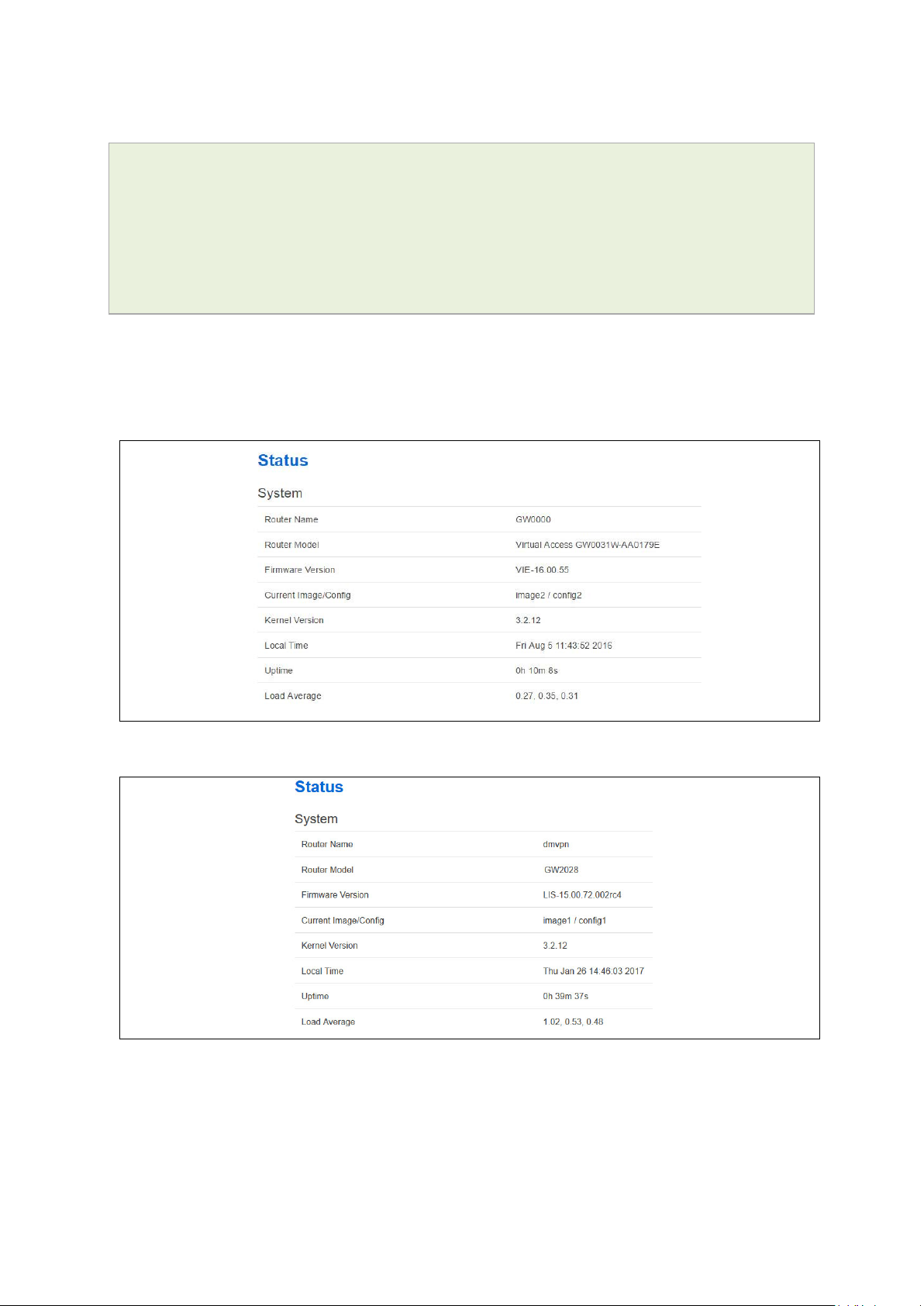
_______________________________________________________________________________________________________
The example below shows the output from the above command.
VA_SERIAL: 00E0C8121215
VA_MODEL: GW0000
VA_ACTIVEIMAGE: image2
VA_ACTIVECONFIG: config1
VA_IMAGE1VER: VIE-16.00.44
VA_IMAGE2VER: VIE-16.00.44
7.2 Identify your software version
To check which software version your router is running, in the top menu, browse to
Status -> Overview.
7: Router file structure
Figure 23: The status page showing a software version prior to 72.002
Figure 24: The status page showing software version 72.002
In the Firmware Version row, the first two digits of the firmware version identify the
hardware platform, for example LIS-15; while the remaining digits: .00.72.002, show
the software version.
_______________________________________________________________________________________________________
© Virtual Access 2018
GW1000 Series User Manual
Issue: 2.3 Page 47 of 463
Page 48

_______________________________________________________________________________________________________
7.3 Image files
The system allows for two firmware image files:
• image1, and
• image2
Two firmware images are supported to enable the system to rollback to a previous
firmware version if the upgrade of one image fails.
The image names (image1, image2) themselves are symbols that point to different
partitions in the overall file system. A special image name “altimag e” exists which always
points to the image that is not running.
The firmware upgrade system always downloads firmware to “altimage”.
7.4 Directory locations for UCI configuration files
Router configurations files are stored in folders on:
7: Router file structure
• /etc/factconf,
• /etc/config1, and
• /etc/config2
Multiple configuration files exist in each folder. Each configura t io n file contains
configuration parameters for different areas of functionality in the system.
A symbolic link exists at /etc/config, which always points to one of factconf, config1 or
config2 is the activ e configuration fi le.
Files that appear to be in /etc/config are actually in /etc /factconf|config1|config2
depending on which configuration is active.
If /etc/config is missing on start-up, for example on first boot, the links and directories
are created with configuration files copied from /rom/etc/config/.
At any given time, only one of the configurations is the active configuration. The UCI
system tool (Unified Configuration Interface) only acts upon the currently active
configuration.
7.5 Viewing and changing current configurati on
To show the configuration currently running, e nt er:
root@VA_router:~# va_config.sh
To show the configuration to run after the next reboot, enter:
root@VA_router:~# va_config.sh next
To set the configuration to run after the next reboot, enter:
root@VA_router:~# va_config.sh -s [factconf|config1|config2|altconfig]
_______________________________________________________________________________________________________
© Virtual Access 2018
GW1000 Series User Manual
Issue: 2.3 Page 48 of 463
Page 49

_______________________________________________________________________________________________________
Command
Target
Description
import
[<config>]
Imports configuration files in UCI sy ntax .
type to the given configuration.
delete
<config>[.<section[.<option>]]
Deletes the given section or option.
7.6 Configuration file syntax
The configuration files consist of sections – or packages - that contain one or more
config statements. These optional statements define actual values.
Below is an example of a simple configuration file.
package 'example'
config 'example' 'test'
option 'string' 'some value'
option 'boolean' '1'
list 'collection' 'first item'
list 'collection' 'second item'
The config 'example' 'test' statement defines the start of a section with the type example
and the name test.
7: Router file structure
export [<config>] Exports the configuration in a machine
readable format. It is used internally to
evaluate configuration file s as shell s cr ip ts .
add <config> <section-type> Adds an anonymous section of type-section
add_list <config>.<section>.<option>=<string> Adds the given string to an existing list
option.
show [<config>[.<section>[.<option>]]] Shows the given option, sectio n or
configuration in compressed notation.
get <config>.<section>[.<option>] Gets the v alue of the giv e n option or the type
of the given section.
Set <config>.<section>[.<option>]=<value> Se ts the v alue of the given optio n, o r add s a
new section with the type set to the given
value.
Table 1: Common commands, target and their descriptions
7.7 Managing con figurations
7.7.1 Managing sets of configuration files using directory manipulation
Configurations can also be managed using directory manipulation.
To remove the contents of the current folder, enter:
root@VA_router:/etc/config1# rm –f *
Warning: the above command makes irreversible changes.
_______________________________________________________________________________________________________
© Virtual Access 2018
GW1000 Series User Manual
Issue: 2.3 Page 49 of 463
Page 50

_______________________________________________________________________________________________________
To remove the contents of a specific folder regardless of the current folder (config2),
enter:
root@VA_router:/ # rm –f /etc/config1/*
Warning: the above command makes irreversible changes.
To copy the contents of one folder into another (config2 into config1), enter:
root@VA_router:/etc/config1# cp /etc/config2/* /etc/config1
7.8 Exporting a configuration file
If you have software versions prior to 72.002, to expor t a configuration file using the
web interface, go to section 7.8.1.
If you have software version 72.002 or above, export a configuration file using the web
interface go to section 7.8.2.
To export a configuration file using UCI, for any software version, go to section 7.8.3.
7: Router file structure
7.8.1 Exporting a configuration file using the web interface for software versions pre- 72.002
The current running configuration file may be exported using the web interfac e.
In the top menu, select Syste m > Backup/Flash Firmware. The Flash operations
page appears.
Figure 25: The flash operations page
In the Backup/Restore section, select Generate Ar chive.
_______________________________________________________________________________________________________
© Virtual Access 2018
GW1000 Series User Manual
Issue: 2.3 Page 50 of 463
Page 51

_______________________________________________________________________________________________________
7: Router file structure
7.8.2 Exporting a configuration file using the web interface for software version
72.002 and above
The current running configuration file may be exported using the web interface.
In the top menu, select System > Flash Operations. The Flash operations page
appears.
Figure 26: The flash operations page
In the Flash Operation section, click the configuration file in t h e Contents column to
download it.
7.8.3 Exporting a configuration file using UCI
You can view any configuration file segment using UCI.
To export the running configuration file, enter:
root@VA_router:~# uci export
To export the factory configuration file, enter:
root@VA_router:~# uci –c /etc/factconf/ export
To export config1 or config2 configuration file, enter:
root@VA_router:~# uci –c /etc/config1/ export
root@VA_router:~# uci –c /etc/config2/ export
7.9 Importing a con figuration file
If you have software versions prior to 72.002, to import a configuration file using the
web interface, go to section 7.9.1.
If you have software version 72.002 or above, to import a configuration file using the
web interface go to section 7.9.2.
_______________________________________________________________________________________________________
© Virtual Access 2018
GW1000 Series User Manual
Issue: 2.3 Page 51 of 463
Page 52

_______________________________________________________________________________________________________
7: Router file structure
To import a configuration file using UCI, for any softw a re version, go to section 7.9.3.
7.9.1 Importing a configuration file using the web interface for software versions pre- 72.002
You can import a configuration file to the alternate conf iguration segment using the web
interface. This will automatically reboot the ro uter into this configuration file.
In the top menu, select System > Backup/Flash Firmware. The Flash operations
page appears.
Figure 27: The flash operations page
Under Backup/Restore, choose Restore Backup: Choose file . Select the appropriate
file and then click Upload archive.
Figure 28: The system – restoring…page
When the ‘waiting for router’ icon disappears, the upgrade is complete, and the login
homepage appears.
_______________________________________________________________________________________________________
© Virtual Access 2018
GW1000 Series User Manual
Issue: 2.3 Page 52 of 463
Page 53
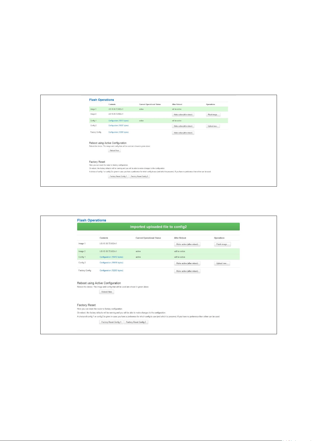
_______________________________________________________________________________________________________
7: Router file structure
7.9.2 Importing a configuration file using the web interface for software version
72.002 and above
You can import a configuration file to the alternate configuration segment using the web
interface.
In the top menu, select System > Flash Operations. The Flash operations page
appears.
Figure 29: The flash operations page
In the Operations colu m n , click Upload new. Select the appropriate file.
Figure 30: The flash operations succeed upload configuration page
If you select ‘Flash image and do not reboot’, the router will only run this configuration if
you click OK to return to the Flash Operations page. There you can manually select
Made Active (after reboot). Then click Reboot Now in the ‘Reboot using Active
Configuration’ section.
_______________________________________________________________________________________________________
© Virtual Access 2018
GW1000 Series User Manual
Issue: 2.3 Page 53 of 463
Page 54

_______________________________________________________________________________________________________
7.9.3 Importing a configuration file using UCI
You can import a configuration file to any file segment using UCI.
To import to config1, enter:
root@VA_router:~# uci –c /etc/config1/ import
<paste in config file>
<CTRL-D>
Note: it is very important that the config file is in the correct format otherwise it will not
import correctly.
7: Router file structure
_______________________________________________________________________________________________________
© Virtual Access 2018
GW1000 Series User Manual
Issue: 2.3 Page 54 of 463
Page 55

_______________________________________________________________________________________________________
8 Using the Command Line Interface
This chapter explains how to view Virtual Access routers' log files and edit conf iguration
files using a Command Line Interface (CLI) and the Unified Configuration Interface (UCI)
system. Some commands may vary between router models.
8.1 Overview of some common commands
Virtual Access routers’ system has an SSH server typically running on port 22.
The factconf default password for the root user is admin.
To change the factconf default password, enter:
root@VA_router:/# uci set system.main.password=”******”
root@VA_router:/# uci commit system
To reboot the system, enter:
8: Using the Command Line Interface
root@VA_router:/# reboot
The system provides a Unix-like command line. Common Unix commands are available
such as ls, cd, cat, top, grep, tail, head, more and less.
Typical pipe and redirect operators are also available, such as: >, >>, <, |
The system log can be viewed using any of the following c ommands:
root@VA_router:/# logread
root@VA_router:/# logread | tail
root@VA_router:/# logread –f
These commands will sho w the full log, end of the log (t ail) and continuously (-f). Enter
Ctrl-C to stop the continuous output from logread -f.
To view and edit configuration files, the system uses the Unified Configuration I nt erface
(UCI) which is described further on in this chapter. This is the preferred method of
editing configuration fi les. However, you can also view and edit these files using some of
the standard Unix tools.
For example, to view a text or configuration file in the system, enter:
root@VA_router:/# cat /etc/passwd
_______________________________________________________________________________________________________
© Virtual Access 2018
GW1000 Series User Manual
Issue: 2.3 Page 55 of 463
Page 56

_______________________________________________________________________________________________________
8: Using the Command Line Interface
The command output information shows the following, or similar output.
root:x:0:0:root:/root:/bin/ash
daemon:*:1:1:daemon:/var:/bin/false
ftp:*:55:55:ftp:/home/ftp:/bin/false
sftp:*:56:56:sftp:/var:/usr/lib/sftp-server
network:*:101:101:network:/var:/bin/false
nobody:*:65534:65534:nobody:/var:/bin/false
To view files in the current folder, enter:
root@VA_router:/# ls
bin etc lib opt sbin usr
bkrepos home linuxrc proc sys var
dev init mnt root tmp www
For more details add the -l argument:
root@VA_router:/# ls -l
drwxrwxr-x 2 root root 642 Jul 16 2012 bin
drwxr-xr-x 5 root root 1020 Jul 4 01:27 dev
drwxrwxr-x 1 root root 0 Jul 3 18:41 etc
drwxr-xr-x 1 root root 0 Jul 9 2012 lib
drwxr-xr-x 2 root root 3 Jul 16 2012 mnt
drwxr-xr-x 7 root root 0 Jan 1 1970 overlay
dr-xr-xr-x 58 root root 0 Jan 1 1970 proc
drwxr-xr-x 16 root root 223 Jul 16 2012 rom
drwxr-xr-x 1 root root 0 Jul 3 22:53 root
drwxrwxr-x 2 root root 612 Jul 16 2012 sbin
drwxr-xr-x 11 root root 0 Jan 1 1970 sys
drwxrwxrwt 10 root root 300 Jul 4 01:27 tmp
drwxr-xr-x 1 root root 0 Jul 3 11:37 usr
lrwxrwxrwx 1 root root 4 Jul 16 2012 var -> /tmp
drwxr-xr-x 4 root root 67 Jul 16 2012 www
_______________________________________________________________________________________________________
© Virtual Access 2018
GW1000 Series User Manual
Issue: 2.3 Page 56 of 463
Page 57

_______________________________________________________________________________________________________
8: Using the Command Line Interface
To change the current folder, enter cd followed by the desired path:
root@VA_router:/# cd /etc/config1
root@VA_router:/etc/config1#
Note: if the specified directory is actually a link to a directory, the real directory will be
shown in the prompt.
To view scheduled jobs, enter:
root@VA_router:/# crontab –l
0 * * * * slaupload 00FF5FF92752 TFTP 1 172.16.250.100 69
To view currently running processes, enter:
root@VA_router:/# ps
PID Uid VmSize Stat Command
1 root 356 S init
2 root DW [keventd]
3 root RWN [ksoftirqd_CPU0]
4 root SW [kswapd]
5 root SW [bdflush]
6 root SW [kupdated]
8 root SW [mtdblockd]
89 root 344 S logger -s -p 6 -t
92 root 356 S init
93 root 348 S syslogd -C 16
94 root 300 S klogd
424 root 320 S wifi up
549 root 364 S httpd -p 80 -h /www -r VA_router
563 root 336 S crond -c /etc/crontabs
6712 root 392 S /usr/sbin/dropbear
6824 root 588 S /usr/sbin/dropbear
7296 root 444 S -ash
374 root 344 R ps ax
375 root 400 S /bin/sh /sbin/hotplug button
384 root 396 R /bin/sh /sbin/hotplug button
385 root RW [keventd]
_______________________________________________________________________________________________________
© Virtual Access 2018
GW1000 Series User Manual
Issue: 2.3 Page 57 of 463
Page 58

_______________________________________________________________________________________________________
To search for a process, enter: pgrep -fl '<process name or part of name>':
root@VA_router:/# pgrep -fl ‘wifi’
424 root 320 S wifi up
To kill a process, enter the PID:
root@VA_router:~# kill 424
8.2 Using Unified Configuration Interface (UCI)
The system uses Unified Configuration Interface (UCI) for central configuration
management. Most common and useful configuration settings can be accessed and
configured using the UCI system.
UCI consists of a Command Line Utility (CLI), the files containing the actual configuration
data, and scripts that take the configuration data and a pp ly it to the proper parts of the
system, such as the networking interfaces. Entering the command 'uci' on its own will
display the list of valid arguments for the command and their format.
8: Using the Command Line Interface
root@VA_router:/lib/config# uci
Usage: uci [<options>] <command> [<arguments>]
Commands:
export [<config>]
import [<config>]
changes [<config>]
commit [<config>]
add <config> <section-type>
add_list <config>.<section>.<option>=<string>
show [<config>[.<section>[.<option>]]]
get <config>.<section>[.<option>]
set <config>.<section>[.<option>]=<value>
delete <config>[.<section[.<option>]]
rename <config>.<section>[.<option>]=<name>
revert <config>[.<section>[.<option>]]
Options:
-c <path> set the search path for config files (default: /etc/config)
-d <str> set the delimiter for list values in uci show
-f <file> use <file> as input instead of stdin
-m when importing, merge data into an existing package
_______________________________________________________________________________________________________
© Virtual Access 2018
GW1000 Series User Manual
Issue: 2.3 Page 58 of 463
Page 59

_______________________________________________________________________________________________________
Command
Target
Description
programs working directly with UCI files .
file or if none given, all configuration files.
type to the given configuration.
delete
<config>[.<section[.<option>]]
Deletes the given section or option.
given name.
section or configuration file.
8: Using the Command Line Interface
-n name unnamed sections on export (default)
-N don't name unnamed sections
-p <path> add a search path for config change files
-P <path> add a search path for config change files and use as default
-q quiet mode (don't print error messages)
-s force strict mode (stop on parser errors, default)
-S disable strict mode
-X do not use extended syntax on 'show'
The table below describes commands for the UCI command line and some further
examples of how to use this utility.
Writes changes of the given configurati o n file ,
or if none is given, all configuration files, to
the filesystem. All "uci set", "uci add", "uc i
rename" and "uci delete" commands are
commit [<config>]
staged into a temporary location and written to
flash at once with "uci commit". This is not
needed after editing configuration f ile s with a
text editor, but for scripts, GUIs and other
export [<config>]
import [<config>] Imports configuration files in UCI sy ntax .
changes [<config>]
add <config> <section-type>
add_list <config>.<section>.<option>=<string> Adds the given string to an existing list option.
show [<config>[.<section>[.<option>]]]
get <config>.<section>[.<option>]
set <config>.<section>[.<option>]=<value>
rename <config>.<section>[.<option>]=<name>
revert <config>[.<section>[.<option>]]
Exports the configuration in a UCI syntax and
does validation.
Lists staged changes to the given configuration
Adds an anonymous section of type section-
Shows the given option, section or
configuration in compressed notation.
Gets the value of the given option or the type
of the given section.
Sets the value of the given option, or add a
new section with the type set to the given
value.
Renames the given option or section to the
Deletes staged changes to the given option,
Table 13: Common commands, target and their descriptions
Note: all operations do not act directly on the configuration files. A commit command is
required after you have finished your configuration.
root@VA_router:~# uci commit
_______________________________________________________________________________________________________
© Virtual Access 2018
GW1000 Series User Manual
Issue: 2.3 Page 59 of 463
Page 60

_______________________________________________________________________________________________________
8.2.1 Using uci commit to avoid router reboot
After changing the port, uhttpd listens on from 80 to 8 08 0 in the file /etc/config/uhttpd;
save it, then enter:
root@VA_router:~# uci commit uhttpd
Then enter:
root@VA_router:~# /etc/init.d/uhttpd restart
For this example, the router does not need to reboot as the changes take effect when
the specified process is restarted.
8.2.2 Export a configuration
Using the uci export command it is possible to view the entire configuration of the router
or a specific package. Using this method to view configurations does not show comments
that are present in the configuration file:
8: Using the Command Line Interface
root@VA_router:~# uci export httpd
package 'httpd'
config 'httpd'
option 'port' '80'
option 'home' '/www'
8.2.3 Show a configuration tree
The configuration tree format displays the full path to each option. This path can then be
used to edit a specific option using the uci set command.
To show the configuration ‘tree’ for a given config, enter:
root@VA_router:/# uci show network
network.loopback=interface
network.loopback.ifname=lo
network.loopback.proto=static
network.loopback.ipaddr=127.0.0.1
network.loopback.netmask=255.0.0.0
network.lan=interface
network.lan.ifname=eth0
network.lan.proto=dhcp
network.wan=interface
network.wan.username=foo
_______________________________________________________________________________________________________
© Virtual Access 2018
GW1000 Series User Manual
Issue: 2.3 Page 60 of 463
Page 61

_______________________________________________________________________________________________________
8: Using the Command Line Interface
network.wan.password=bar
network.wan.proto=3g
network.wan.device=/dev/ttyACM0
network.wan.service=umts
network.wan.auto=0
network.wan.apn=arkessa.com
network.@va_switch[0]=va_switch
network.@va_switch[0].eth0=A B C
network.@va_switch[0].eth1=D
It is also possible to display a limited subset of a conf iguration:
root@VA_router:/# uci show network.wan
network.wan=interface
network.wan.username=foo
network.wan.password=bar
network.wan.proto=3g
network.wan.device=/dev/ttyACM0
network.wan.service=umts
network.wan.auto=0
network.wan.apn=hs.vodafone.ie
8.2.4 Display just the value of an option
To display a specific value of an individual option within a package, enter:
root@VA_router:~# uci get httpd.@httpd[0].port
80
root@VA_router:~#
8.2.5 High level image commands
To show the image running currently, enter:
root@VA_router:~# vacmd show current image
To set the image to run on next reboot, enter:
root@VA_router:~# vacmd set next image [image1|image2|altimage]
root@VA_router:~# reboot
_______________________________________________________________________________________________________
© Virtual Access 2018
GW1000 Series User Manual
Issue: 2.3 Page 61 of 463
Page 62

_______________________________________________________________________________________________________
8.2.6 Format of multiple rules
When there are multiple rules next to each other, UCI uses array-like references for
them. For example, if there are 8 NTP servers, UCI will let you reference their sections
as timeserver.@timeserver[0] for the first section; or timeserver.@timeserver[7]
for the last section.
You can also use negative indexes, such as timeserver.@timeserver[-1] ‘-1’ means
the last one, and ‘-2’ means the second -to-last one. This is useful whe n appending new
rules to the end of a list.
root@VA_router:/# uci show va_eventd
va_eventd.main=va_eventd
va_eventd.main.enabled=yes
va_eventd.main.event_queue_file=/tmp/event_buffer
va_eventd.main.event_queue_size=128K
va_eventd.@conn_tester[0]=conn_tester
8: Using the Command Line Interface
va_eventd.@conn_tester[0].name=Pinger
va_eventd.@conn_tester[0].enabled=yes
va_eventd.@conn_tester[0].type=ping
va_eventd.@conn_tester[0].ping_dest_addr=192.168.250.100
va_eventd.@conn_tester[0].ping_success_duration_sec=5
va_eventd.@target[0]=target
va_eventd.@target[0].name=MonitorSyslog
va_eventd.@target[0].enabled=yes
va_eventd.@target[0].type=syslog
va_eventd.@target[0].target_addr=192.168.250.100
va_eventd.@target[0].conn_tester=Pinger
va_eventd.@target[0].suppress_duplicate_forwardings=no
va_eventd.@forwarding[0]=forwarding
va_eventd.@forwarding[0].enabled=yes
va_eventd.@forwarding[0].className=ethernet
va_eventd.@forwarding[0].target=MonitorSyslog
va_eventd.@forwarding[1]=forwarding
va_eventd.@forwarding[1].enabled=yes
va_eventd.@forwarding[1].className=auth
va_eventd.@forwarding[1].target=MonitorSyslog
va_eventd.@forwarding[2]=forwarding
va_eventd.@forwarding[2].enabled=yes
va_eventd.@forwarding[2].className=adsl
_______________________________________________________________________________________________________
© Virtual Access 2018
GW1000 Series User Manual
Issue: 2.3 Page 62 of 463
Page 63

_______________________________________________________________________________________________________
File
Description
Management
/etc/config/monitor
Monitor details
/etc/config/dhcp
Dnsmasq configuration and DHCP setting s
/etc/config/system
Misc. system settings including sys l og
Other
/etc/config/uhttpd
Web server options (uHTTPd)
/etc/config/strongswan
IPSec settings
va_eventd.@forwarding[2].target=MonitorSyslog
va_eventd.@forwarding[3]=forwarding
va_eventd.@forwarding[3].enabled=yes
va_eventd.@forwarding[3].className=ppp
va_eventd.@forwarding[3].target=MonitorSyslog
8.3 Configuration files
The table below lists common package configuration files that can be edited using uci
commands. Other configuration files may also be present depending on the specific
options available on the Virtual Access router.
/etc/config/autoload Boot up Activation behaviour (typically used in factconf)
/etc/config/httpclient Activator addresses and urls
8: Using the Command Line Interface
Basic
/etc/config/dropbear SSH server options
/etc/config/firewall NAT, packet filter, port forwarding, etc.
/etc/config/network Switch, inte rface, L2TP and route configuration
/etc/config/snmpd SNMPd settings
8.4 Configuration file syntax
The configuration files usually consist of one or more config statemen t s, so-called
sections with one or more option statements defining the actual values.
Below is an example of a simple configuration file.
package 'example'
config 'example' 'test'
option 'string' 'some value'
option 'boolean' '1'
list 'collection' 'first item'
list 'collection' 'second item'
The config 'example' 'test' statement defines the start of a section with the type
example and the name test. There can also be so-called anonymous sections with only a
type, but no name identifier. The type is important for the processing programs to
decide how to treat the enclosed options.
_______________________________________________________________________________________________________
© Virtual Access 2018
GW1000 Series User Manual
Issue: 2.3 Page 63 of 463
Page 64

_______________________________________________________________________________________________________
8: Using the Command Line Interface
The option 'string' 'some value' and option 'boolean' '1' lines define simple
values within the section.
Note: there are no syntactical differences between text and boolean options. Per
convention, boolean options may have one of the values '0', 'no', 'off' or 'false' to
specify a false value or '1' , 'yes', 'on' or 'true' to specify a true value.
In the lines starting with a list keyword, an option wit h multiple va lues is defined. All list
statements that share the same name collection in our example will be combined into a
single list of values with the sa me order as in th e configuration file.
The indentation of the option and list stateme nts is a conv ention to improve the
readability of the configuration file but it is not syntactically required.
Usually you do not need to enclose identifiers or v alues in quotes. Quotes are only
required if the enclosed value contains spaces or tabs. Also it is legal to use doublequotes instead of single-quotes when typing configuration options.
All of the examples below are valid syntax.
option example value
option 'example' value
option example "value"
option "example" 'value'
option 'example' "value"
In contrast, the following examples are not valid syntax.
option 'example" "value'
Quotes are unbalanced.
option example some value with space
Missing quotes around the value.
It is important to note that identifiers and config file names may only contain the
characters a-z, A-Z, 0-9 and _. However, option values may contain any character, as
long they are properly quoted.
_______________________________________________________________________________________________________
© Virtual Access 2018
GW1000 Series User Manual
Issue: 2.3 Page 64 of 463
Page 65

_______________________________________________________________________________________________________
9 Upgrading router firmware
This chapter describes how to upgrade router firmware. The upgrade process is as
follows:
• Firmware is transferred to the device.
• Firmware is checked to ensure there are no corruptions.
• Firmware is saved to persistent storage.
• Data in persistent storage is validated.
To avoid any unrecoverable errors during the process, you must follow several safety
steps described in this chapter.
On successful comp letion of the process, yo u can r estart the device running the new
firmware.
9.1 Software versions
9: Upgrading router firmware
If you have software versions prior to 72.002, to upgrade firmware using the web
interface, go to section 9.1.2.
If you have software version 72.002 or above, to upgrade firmware using the web
interface go to section 9.1.3.
To upgrade firmware using CLI, for any software version, go to section 9.2.
9.1.1 Identify your software version
To check which software version your router is running, in the top menu, browse to
Status -> Overview.
Figure 31: The status page showing a software version prior to 72.002
_______________________________________________________________________________________________________
© Virtual Access 2018
GW1000 Series User Manual
Issue: 2.3 Page 65 of 463
Page 66

_______________________________________________________________________________________________________
9: Upgrading router firmware
Figure 32: The status page showing software version 72.002
In the Firmware Version row, the first two digits of the firmware version identify the
hardware platform, for example LIS-15; while the remaining digits: .00.72.002, show
the software version.
9.1.2 Upgrading router firmware for software versions pre- 72.002
Copy the new firmware issued by Virtual Access to a PC connected to the router.
In the top menu, select System tab -> Backup/Flash F i rm w are. The Flash operations
page appears.
Figure 33: The flash operations page
_______________________________________________________________________________________________________
© Virtual Access 2018
GW1000 Series User Manual
Issue: 2.3 Page 66 of 463
Page 67

_______________________________________________________________________________________________________
9: Upgrading router firmware
Under Flash new firmware image, click Choose File or Browse.
Note: the button will vary depending on the browser you are using.
Select the appropriate image and then click Flash Image. The Flash Firmware – Verify
page appears.
Figure 34: The flash firmware - verify page
Click Proceed. The System – Flashing… page appears.
Figure 35: The system – flashing…page
When the ‘waiting for router’ icon disappears, the upgrade is complete, and the login
homepage appears.
To verify that the router has been upgraded successfully, click Status in the top menu.
The Firmware Version shows in the system list.
Figure 36: The system status list
_______________________________________________________________________________________________________
© Virtual Access 2018
GW1000 Series User Manual
Issue: 2.3 Page 67 of 463
Page 68

_______________________________________________________________________________________________________
9: Upgrading router firmware
9.1.3 Upgrading router firmware for software version 72.002 and above
Copy the new firmware issued by Virtual Access to a PC connected to the router.
In the top menu, select System tab > Flash operations. The Flash operations page
appears.
Figure 37: The flash operations page
Under Flash Operations, click Flash Image. Only the inactive image is available to flas h.
Select the appropriate image and then wait until image has loaded.
Note: this process may take a while depending on the available connection speed.
When the image has loaded, the Update Firmware page appears.
Figure 38: The flash firmware - verify page
Click either: Flash image and do not reboot, or Flash image and reboot using new
image immediat ely. The ‘Firmware update is being applied’ message appears.
When the firmware update is complete, the Update Firmware page appears. There are
various messages, de p end ing on which option you sele cted, or if any corruptio ns have
occurred.
_______________________________________________________________________________________________________
© Virtual Access 2018
GW1000 Series User Manual
Issue: 2.3 Page 68 of 463
Page 69

_______________________________________________________________________________________________________
9.1.4 Flash image and do not reboot option
Figure 39: The firmware update pag e after ‘…do not reboot’ option selected
9: Upgrading router firmware
If you select ‘Flash image and do not reboot’, the router will only run the firmware if you
click OK to return to the Flash Operations page. There you can manually select Made
Active (after reboot). Then click Reboot Now in the ‘Reboot using Active
Configuration’ section.
9.1.5 Update flash image and reboot using new image immediately option
Figure 40: The firmware update pag e after ‘update flash image and reboot…’ option selected
If you select ‘Update flash image and reboot using new image immediately’ and the
overall validation and flashing process has succeeded, the router will reboot
immediately. To regain access to the router you must login again. If any part of the
processes encounters an error the reboot does not occur and a report is given.
_______________________________________________________________________________________________________
© Virtual Access 2018
GW1000 Series User Manual
Issue: 2.3 Page 69 of 463
Page 70

_______________________________________________________________________________________________________
9.1.6 Possible file corruption
Figure 41: The firmware update failure page
9: Upgrading router firmware
In the unfortunate event that the firmware upgrade fails, the ‘Failed verification File is
most likely corrupt’ or similar message will appear in the Verify file integrity row. No
changes will be made to the system and the general message File verification failed
appears.
9.1.7 Verify the firmware has been upgraded successfully
To check the firmware version, in the top menu, browse to System -> Flash
Operations, or after router reboots, in the top menu, click Status. The Firmware
Version shows in the system list and also in the right top corner of the menu bar.
Figure 42: The system status list showing current firmware version
_______________________________________________________________________________________________________
© Virtual Access 2018
GW1000 Series User Manual
Issue: 2.3 Page 70 of 463
Page 71

_______________________________________________________________________________________________________
9.2 Upgrading firmware using CLI
9.2.1 Transfer file to router
To upgrade firmware using CLI, you will need a TFTP server on a connected PC or SCP
available.
Open up an SSH or Telnet session to the router.
Enter in the relevant username and password.
To access the temp folder, enter cd /tmp
Depending on the router’s so ftware version the following TFTP clients are available:
• atftp
• curl
To determine which is available on your router, enter:
which curl || which atftp
The output shows the available application:
9: Upgrading router firmware
/usr/bin/curl
ATFTP
Inline command usage:
atftp -g -r LIS-15.00.72.002.image –l /tmp/LIS-15.00.72.002.image x.x.x.x
where x.x.x.x is the IP address of your PC, -g is get operation and -l / -r are local and
remote file name to store.
CURL
Inline command usage:
curl tftp://x.x.x.x/LIS-15.00.72.002.image -o /tmp/LIS-15.00.72.002.image
where x.x.x.x is the IP of your PC, -o is local file name to store.
SCP
Secure Copy (SCP) is a part of Secure Shell (SSH) and ena bles file transfers to the
router using authentication and encryption. It is different to TFTP, which uses UD P, while
SCP uses a TCP connection. On Unix machines, SCP is a standard part of the sys te m ; on
Windows it requires an additiona l application.
The usage example below is for a Unix machine and therefore assumes the image file is
in the current folder.
scp LIS-15.00.72.002.image root@x.x.x.x:/tmp/LIS-15.00.72.002.image
_______________________________________________________________________________________________________
© Virtual Access 2018
GW1000 Series User Manual
Issue: 2.3 Page 71 of 463
Page 72

_______________________________________________________________________________________________________
Where the first argument ‘LIS-15.00.72.002.image’ in SCP is the source and the second
argument ‘tmp/LIS-15.00.72.002.image’ is the destination path, enter root as the
username to connect to x.x.x.x IP address.
After you execute the above command you will be asked to provide a root password.
At this stage the output shows the process of copying the so ftware file into destination
directory.
root@192.168.100.1’s password:
LIS-15.00.72.000.image 100% 6812KB 2.2MB/s 00:03
9.2.2 Image verification before flashing
To verify the integrity of the image, firmware version xx.yy.72.002 and later uses an
image-check application.
Note: it is the user’s responsibility to verify the image before starting to write the image
to flash process.
9: Upgrading router firmware
To use the image-check on downloaded image, enter:
image-check /tmp/LIS-15.00.72.002.image
In the case of any image corruption, an appropriate error message appears:
Error: no SquashFS filesystem after CRC'd section - data length 3
Error: read failed, expected at least 3 more bytes
or similar.
Note: the image is valid only if no error message appears. This process is done
automatically during Web UI firmware update.
9.2.3 Flashing
When downloaded firmware verification succeeds, the new image can be written to flash.
To write the image into the alternative image, enter:
mtd write LIS-15.00.72.002.image altimage
Note: this is an example, substitute the correct file name.
9.2.4 Flash verification after flashing
After the write process has finished, you must complete a post verification of the
firmware.
To verify the checksum of downloaded firmware, enter:
va_image_csum.sh /tmp/LIS-15.00.72.002.image
_______________________________________________________________________________________________________
© Virtual Access 2018
GW1000 Series User Manual
Issue: 2.3 Page 72 of 463
Page 73

_______________________________________________________________________________________________________
9: Upgrading router firmware
The checksum of the downloaded binary is shown:
08761cd03e33c569873bcc24cf2b7389 7006920 LIS-15.00.72.002 This MD5
To verify the checksum of written firmware, enter:
va_image_csum.sh alt
After a while the checksum will be calculated:
Calculating checksum.........
08761cd03e33c569873bcc24cf2b7389 7006920 LIS-15.00.72.002 This MD5
Verify and compare the checksum with the MD5 sum of the downloaded image.
If the checksum of the written firmware in altimage matches the one from the
downloaded image in /tmp, the new firmware has been programmed successfully.
9.2.5 Setup an alternative image
Provided the programming has succeeded, you can set it as the next image to use after
reboot; enter:
vacmd set next image altimage
To reboot using the new firmware, enter:
reboot
9.3 Firmware recovery
The router has an automatic boot recovery feature that will
• revert the active firmware to the alternate firmware segment on three
consecutive failed software restarts.
• Change the boot configuration to factory configuration after ten failed restarts
By design this feature is intended to allow recovery from firmware problems and
therefore excludes restarts due to power loss.
_______________________________________________________________________________________________________
© Virtual Access 2018
GW1000 Series User Manual
Issue: 2.3 Page 73 of 463
Page 74

_______________________________________________________________________________________________________
Package
Sections
main
syslog_fillter
timeserver
10 System settings
The system section contains settings that apply to the most basic operation of the
system, such as the host name, time zone, logging details, NTP server, language and
style.
The host name appears in the top left hand corner of the interface menu bar. It also
appears when you open a Telnet or SSH session.
Note: this document shows no host name in screen shots. Throughout the document we
use the host name ‘VA_router’.
The system configurat ion contains a logging section for the configuration of a Syslog
client.
10.1 Syslog overview
Most syslog settings appear in the main System Configuration page.
Syslog messages have a timestamp, source facility, priority, and message section. Often
the message section begins with an optional tag identifyi ng the usermode program name
and process ID responsible for the message.
10: System settings
Messages can be stored locally and also forwarded remotely. Separate filter options
apply to each case. At a broad level, you can set the minimum severity level for local
and remote targets; only messages with a priority more severe than the configured level
will be recorded.
Kernel messages are recorded separately in their own buffer. However, for convenience,
these are copied to the system log automatically so that a unified system log is
available.
In addition, you can also define filter rules to determine how particular log messages are
handled. For example, you may decide that certain debug messages are directed into
their own log file, to avoid cluttering up the main system log, and to save bandwidth if
delivering to a remote syslog server. You can define filters to be applied to local and
remote targets, or both. A filter matches specific log messages and then determines an
action for them.
10.2 Configuration package use d
system
_______________________________________________________________________________________________________
© Virtual Access 2018
GW1000 Series User Manual
Issue: 2.3 Page 74 of 463
Page 75
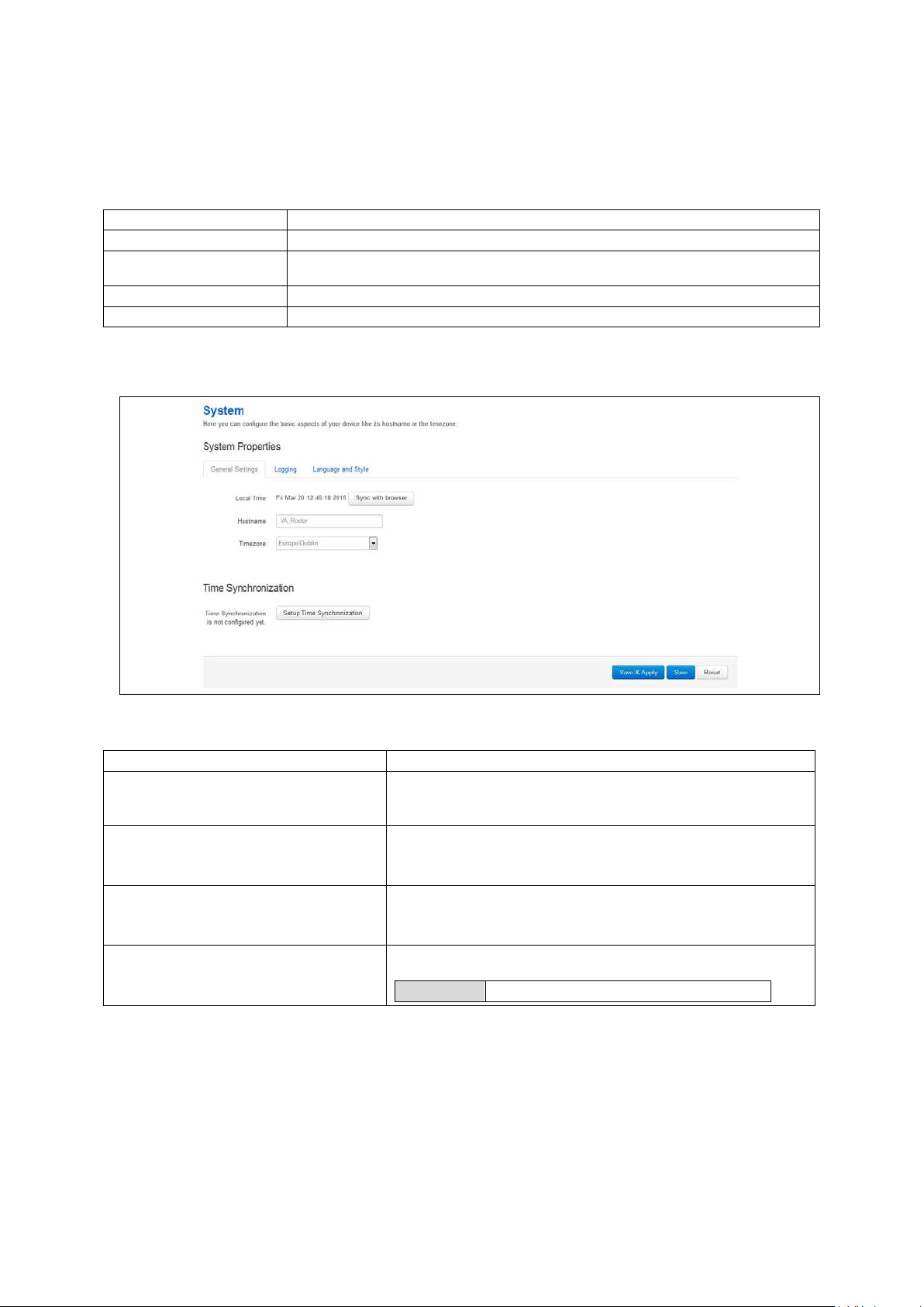
_______________________________________________________________________________________________________
Section
Description
General settings
Configure host name, local time and time zone.
section.
Language and Style
Configure the router’s web language and style.
Time synchronization
Configure the NTP server in this section.
Web Field/UCI/Packag e Optio n
Description
date –s YYYY.MM.DD-hh:mm:ss
Opt: hostname
Opt: timezone
Opt: time_save_interval_m in
10m
10.3 Configuring s ystem properties
To set your system properties, select System -> System. There are four sections in the
System page.
Logging Co nfigure a router to log to a server. You can configure a Syslog client in this
10.3.1 General settings
10: System settings
Web: Local Time
Web: hostname
UCI: system.main.hostname
Web: Timezone
UCI: system.main.timezone
Web: n/a
UCI: system.main.timezone
Table 14: Information table for general settings section
Figure 43: General settings in system properties
Sets the local time and syncs with browser. You can manually
configure on CLI, using:
Specifies the hostname for this system .
Specifies the time zone that the date and time should be
rendered in by default.
Defines the interval in minutes to store the loca l time for use o n
next reboot.
_______________________________________________________________________________________________________
© Virtual Access 2018
GW1000 Series User Manual
Issue: 2.3 Page 75 of 463
Page 76
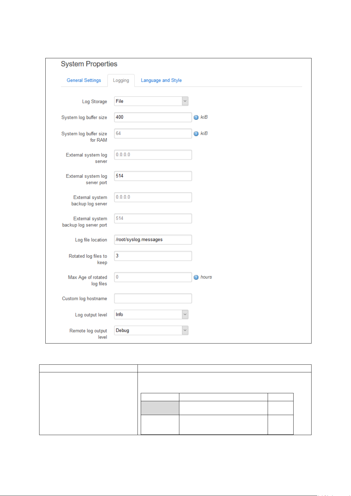
_______________________________________________________________________________________________________
Web Field/UCI/Packag e Optio n
Description
Web value
Description
UCI
reboot. Viewed using logread
Viewed using cat /log_file
10.3.2 Logging
10: System settings
Web: Log st orage
UCI: system.main.log_type
Opt: log_type
_______________________________________________________________________________________________________
© Virtual Access 2018
GW1000 Series User Manual
Issue: 2.3 Page 76 of 463
Figure 44: The logging section in system properties
Defines the system log storage type. Messages stored in RAM can be
seen using logread.
Note: system log stored in RAM will be lost on reboot.
RAM Store system log in RAM. Lost on
File Store sy s te m log in flash.
Maintained through reboot.
circular
file
Page 77
_______________________________________________________________________________________________________
Range
16
16 KB
Range
16
16 KB
Range
IP of FQDN
0.0.0.0
Range
514
Range
IP or FQDN
0.0.0.0
Opt: log_port_backup
Range
514
Range
/root/syslog
Range
1 Store 1 archive log file in flash.
Range
0 No age limit
Range
messages.
10: System settings
Web: System log buffer size
UCI: system.main.log_size
Opt: log_size
Web: System log buffer size for RAM
UCI: system.main.log_size_ram
Opt: log_size_ram
Web: External system log server
UCI: system.main.log_ip
Opt: log_ip
Web: External system log server port
UCI: system.main.log_port
Opt: log_port
Web: External system backup log
server
UCI: system.main.log_ip_backup
Opt: log_ip_backup
Web: External system backup log
server port
UCI: system.main.log_port_backup
File log buffer size in KB.
Note: when the file reaches the configured siz e it is copied to the
archive file (log_file_name.0).
RAM log buffer size in KB.
External syslog server IP address. If defined syslog messages will be
sent in addition to local storage.
External syslog server port number.
Backup external syslog server IP address. If defined syslog messa g es
will be sent here in addition to the main log server.
External syslog server port number for use with backup server.
Web: Log file location
UCI: system.main.log_file
Opt: log_file
Web: Rotated log files to keep
UCI: system.main.log_file_c ount
Opt: log_file_count
Web: Max Age of rotated log files
UCI: system.main.log_age
Opt: log_age
Web: Custom log hostname
UCI: system.main.log_hostname
Opt: log_hostname
Defines the file path for log storage when Log Storage is se t to ‘file’ .
Note: when the file reaches the configured siz e it is copied to the
archive file (log_file_name.0).
Set to: root/syslog.messages
Defines the file number of archive files for storage in flash when Log
Storage is set to ‘file’.
When the system log file reaches the configured size it is copie d to
the archive file (log_file_name.0). Existing archive files are copied to
log_file_name.(x+1).
Defines the maximum duration in hours before archive syslog files are
deleted.
Set to 0 to define no age limit.
Defines a custom host name for syslog messages.
Magic values %hostname (system hostnam e ), %ser (serial), and
%mon (Monitor dev_reference) are als o recog nis ed .
Empty Use router hostname for syslog
_______________________________________________________________________________________________________
© Virtual Access 2018
GW1000 Series User Manual
Issue: 2.3 Page 77 of 463
Page 78

_______________________________________________________________________________________________________
Web value
Description
UCI
debugging the application.
require no action.
error conditions.
if action is not taken.
Error
Error conditions
4
Critical
Critical conditions
3
Alert
Should be addressed immediately
2
Emergency
System is unusable
1
Web value
Description
UCI
debugging the application.
require no action.
error conditions.
if action is not taken.
Error
Error conditions.
4
Critical
Critical conditions.
3
Alert
Should be addr essed immed i ately.
2
Emergency
System is unusable.
1
1
Enable
0
Disable
1
Enable
0
Disable
Range
6
6 hours
Range
1024
6 hours
10: System settings
Web: Log output level
UCI: system.main.conloglev e l
Opt: conloglevel
Web: Remote log output level
UCI: system.main. remoteloglevel
Opt: remoteloglevel
Sets the maximum log output level severity for system events.
System events are written to the system log. Messages with a lowe r
level or level equal to the configured level are disp laye d on the
console using the logread command, or alternatively written to a flash
file, if configured to do so.
Debug Information useful to developers for
Info Normal operational messages that
Notice Events that are unusual, but not
Warning May ind i c ate that an error will o ccur
8
7
6
5
Sets the maximum log output level severity for system events sent to
remote syslog server.
Debug Information useful to developers for
Info Normal operational messages that
8
7
Web: n/a
UCI: system.main.audit_shel l
Opt: audit_shell
Web: n/a
UCI: system.main.audit_cfg
Opt: audit_cfg
Web: n/a
UCI:
system.main.audit_cfg_hul_interval_h
ours
Opt: audit_cfg_hul_interval_hours
Web: n/a
UCI:
system.main.audit_cfg_max_size_kb
Opt: audit_cfg_max_size_kb
Notice Events that are unusual, but not
Warning May ind i c ate that an error will o ccur
6
5
Log every command executed in shell.
Log changes made to configuration file through any interface.
Defines the interval, in hours, at which configuration changes are
uploaded to Activator.
Set to 0 to disable.
Defines the maximum size audit data can take in flash in 1024 byte
units.
_______________________________________________________________________________________________________
© Virtual Access 2018
GW1000 Series User Manual
Issue: 2.3 Page 78 of 463
Table 15: Information table for the logging section
Page 79
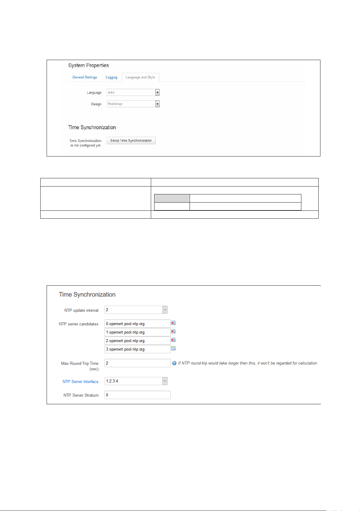
_______________________________________________________________________________________________________
Web Field/UCI/Packag e Optio n
Description
Auto
English
Design
Sets the router’s style.
10.3.3 Language and style
Figure 45: The language and style section in system properties
Language Sets the language to ‘auto’ or ‘English’.
10: System settings
Table 16: Information table for the language and style page
10.3.4 Time synchronization
The router time must be synchronized using NTP. The router can act as both an NT P
client and an NTP server. It is enabled as an NTP client by default and individual
interfaces can be configured to respond to NTP requests.
_______________________________________________________________________________________________________
© Virtual Access 2018
GW1000 Series User Manual
Issue: 2.3 Page 79 of 463
Figure 46: The time synchronization section in system properties
Page 80

_______________________________________________________________________________________________________
Web Field/UCI/Packag e Optio n
Description
Auto
Range
auto; 1-23
By default all fields are set to 0.0.0.0.
2
Two seconds.
Range
Blank
Do not respond to NTP requests.
Range
Blank
NTP server will derive stratum
Range
10: System settings
Web: NTP update interval
UCI: system.ntp.interval_hours
Opt: interval_hours
Web: NTP server candidates
UCI: system.ntp.server
Opt: list server
Web: Max Round-Tip Time (secs)
UCI: system.ntp.max_ntp_roundtrip_sec
Opt: max_ntp_roundtrip_sec
Web: NTP Server Interface
UCI: system.ntp.listen
Opt: listen
Web: NTP Server Stratum
UCI: system.ntp.stratum
Opt: stratum
Specifies interval of NTP requests in hours. Default value set to
auto.
Defines the list of NTP servers to poll the time from. If the list is
empty, the built-in NTP daemon is not started. Multip le serv e rs
can be configured and are separated by a space if using UCI.
Defines the maximum time in seconds for an NTP poll. Any polls
that take longer than this will be not be used for NTP calculation.
Defines a list of interfaces that respond to NTP requests .
Interfaces should be delimited using sp ac e . Example :
option listen ‘LAN1 LAN2’
Defines how far this NTP Server is from the reference clock. For
example, an NTP server getting time directly from the reference
clock will have a stratum of 1. In general, this should be lef t
blank, which means that the router NTP Server will der ive the
stratum from the NTP dialogue.
10.3.5 System reboot
The router can be configured to reboot immediately, or sche duled to reboot a configured
time in the future.
In the top menu, select System -> Reboot. The System page appears.
Ensure you have saved all yo ur configuration chang es before you reboot.
Table 17: Information table for time synchronization secti o n
Check the Reboot now check box and then click Reboot.
_______________________________________________________________________________________________________
© Virtual Access 2018
GW1000 Series User Manual
Issue: 2.3 Page 80 of 463
Figure 47: The reboot page
Page 81

_______________________________________________________________________________________________________
Section
Description
system
General system configuration options
timeserver
Router time and NTP conguration options
syslog_filter
Advanced filter rules (see Advanced filter section)
10.4 System settings usi ng command line
System settings are configured under the system package /etc/config/system. There
are several configuration sections.
10.4.1 System setti n gs using UCI
root@VA_router:~# uci show system
system.main=system
system.main.hostname=VA_router
system.main.timezone=UTC
system.main.log_ip=1.1.1.1
10: System settings
system.main.log_port=514
system.main.remoteloglevel=8
system.main.log_file=/root/syslog.messages
system.main.log_size=400
system.main.log_type=file
system.main.log_file_count=3
system.main.conloglevel=8
system.main.cronloglevel=8
system.ntp.interval_hours=auto
system.ntp.server=0.VA_router.pool.ntp.org 10.10.10.10
10.4.2 System settings using package options
root@VA_router:~# uci export system
package 'system'
config 'system' 'main'
option 'hostname' "VA_router"
option 'timezone' "UTC"
option 'log_ip' "1.1.1.1"
option 'log_port' "514"
option remoteloglevel '8'
option log_file '/root/syslog.messages'
option log_size '400'
_______________________________________________________________________________________________________
© Virtual Access 2018
GW1000 Series User Manual
Issue: 2.3 Page 81 of 463
Page 82

_______________________________________________________________________________________________________
Facitity
Description
auth
Authorisation/security
authpriv
Authorisation (private)
cron
Scheduled jobs
daemon
Background daemons
kern
Kernel messages
local0
hotplug scripts
security
Same as auth
syslog
Internal syslog events
user
General user-mode application messages
Level
Name
Description
0
emerg
System is unusable
1
alert
Immediate action required
2
crit
Critical conditions
3
error
Error conditions
4
warning
Warning conditions
5
notice
Normal but significant
6
info
Informational
7
debug
Debug-level messages
-
none
No priority
option log_type 'file'
option log_file_count '3'
option time_save_interval_min "10"
option conloglevel '8'
option cronloglevel '8'
config 'timeserver' 'ntp'
option interval_hours 'auto'
list server "0.VA_router.pool.ntp.org"
list server ’10.10.10.10’
option listen ‘LAN1 LAN2’
10.5 System diagnostics
10: System settings
10.5.1 System log messages
System log messages comprise of a date, source facility, hostname, severity and
message description in the form tag: message.
10.5.1.1 Source facility list:
10.5.1.2 Event severity list
The severities are ordered from most severe to least severe.
Table 18: Syslog message severity list
_______________________________________________________________________________________________________
© Virtual Access 2018
GW1000 Series User Manual
Issue: 2.3 Page 82 of 463
Table 19: Syslog message severity list
Page 83

_______________________________________________________________________________________________________
10.5.1.3 System log messages in RAM
By default, system log messages are stored in the system log in RAM.
To view the system log in RAM, enter:
root@VA_router:~# logread
Shows the log.
root@VA_router:~# logread |tail
Shows end of the log.
root@VA_router:~# logread | more
Shows the log page by page.
root@VA_router:~# logread –f
Shows the log on an ongoing basis. To stop this option, press ctrl-c.
10: System settings
root@VA_router:~# logread –f &
Shows the log on an ongoing basis while in the background. This allows you to run other
commands while still tracing the event logs. To stop this option, type fg to view the
current jobs, then press ctrl-c to kill those jobs.
10.5.1.4 System log messages in flash
Since logread is limited by memory size and does not survive a reset, it is beneficial t o
write system messages to flash memory. To do t his, modify the system config under the
system package. Set the options ‘log_file’, ‘log_size’, ‘log_type’and ‘log_file_count’
as shown below:
root@VA_router:~# uci export system
package system
config system 'main'
option hostname 'VA_router'
option zonename 'UTC'
option timezone 'GMT0'
option conloglevel '8'
option cronloglevel '8'
option time_save_interval_hour '10'
option log_hostname '%serial'
option log_ip '1.1.1.1'
option log_port '514'
option log_file '/root/syslog.messages'
_______________________________________________________________________________________________________
© Virtual Access 2018
GW1000 Series User Manual
Issue: 2.3 Page 83 of 463
Page 84

_______________________________________________________________________________________________________
10: System settings
option log_size '400'
option log_type 'file'
option log_file_count '3'
The above commands will take effect after a reboot, or by running the console
command:
root@VA_router:~# /etc/init.d/syslogd restart
root@VA_router:~# cat /root/syslog.messages
Shows all the system events stored in flash.
root@VA_router:~# tail /root/syslog.messages
Shows end of the events stored flash.
root@VA_router:~# tail –f /root/syslog.messages &
Shows the log on an ongoing basis. To stop this option, press ctrl-c.
10.5.2 Kernel messages
To view kernel messages, enter dmesg
root@VA_router:~# dmesg
[ 0.000000] Linux version 3.10.12 (info@virtualaccess.com) (gcc version
4.8.1 20130401 (prerelease) (Linaro GCC 4.8-2013.04) ) #130 PREEMPT 197001-01T00:00:00Z
[ 0.000000] SoC: xRX330 rev 1.1
[ 0.000000] bootconsole [early0] enabled
[ 0.000000] CPU0 revision is: 00019556 (MIPS 34Kc)
[ 0.000000] adding memory size:267386880 from DT
[ 0.000000] MIPS: machine is Virtual Access GW6600V series
[ 0.000000] Determined physical RAM map:
[ 0.000000] memory: 0ff00000 @ 00000000 (usable)
[ 0.000000] User-defined physical RAM map:
[ 0.000000] memory: 07200000 @ 00000000 (usable)
Note: kernel messages are also copied to the main system log by default.
10.5.3 Syslog process
To check the syslog process is running correctly, enter pgrep –fl syslogd
_______________________________________________________________________________________________________
© Virtual Access 2018
GW1000 Series User Manual
Issue: 2.3 Page 84 of 463
Page 85

_______________________________________________________________________________________________________
root@VA_router:~# pgrep -fl syslogd
5409 /sbin/syslogd -h VARouter -L -R 192.168.14.202:514 -l 7 -r 8 -s 400 -O
/root/syslog.messages -b 3 -C64 -R localhost:2048
Changes to the syslog configuration will take effect with a restart of syslogd
root@VA_router:~# /etc/init.d/syslogd restart
10.5.4 NTP process
To check the NTP process is running correctly, enter pgrep –fl chrony
root@VA_router:~# pgrep -fl chrony
2553 /usr/sbin/chronyd -f /etc/chrony.conf
Changes to the NTP configuration will take effect with a restart of chrony
10: System settings
root@VA_router:~# /etc/init.d/chrony restart
10.6 Advanced filtering of syslog messages
Syslog messages can be filtered against a series of rules that are checked for
each message generated. If a match is found, then the specified action is taken.
If no match occurs, then the default action is taken, as defined in the main
system logging settings.
A message may match multiple filters. They are processed in the order listed.
For example, you may wish to record authorisation messages in the main
system log, but also make a copy in a separate authorisation log which can span
a much longer period of time.
By default, all matching filters will be applied to each message. However, you
can mark a filter to indicate that after it matches, no further filter processing
should take place.
The filter rules are defined in a free-form text list in the syslog_filter configuration
section. There are two section types, one for messages to be stored locally, and one for
messages delivered remotely.
Configuring advanced filters on the web interface is not currently supported; they must
be edited using the command line interface.
10.6.1 Advanced filtering using command line
Filters are defined in the syslog_filter configuration section of the system package. A
set of filters can be eit h er local or remote.
• All messages are matched against both local and remote filter rules, if configured.
_______________________________________________________________________________________________________
© Virtual Access 2018
GW1000 Series User Manual
Issue: 2.3 Page 85 of 463
Page 86

_______________________________________________________________________________________________________
Section
Description
Use the wildcard '*' to match all facilities.
Use the wildcard '*' to match all facilities.
10: System settings
• Each local filter matched is executed; if there is no match, then the default local
logging action applies.
• Any remote filter matched is executed; if there is no match, then the default
remote logging action applies.
root@VA_router:~# uci export system
package system
……
config syslog_filter 'local'
list text "...line 1..."
list text "...line 2..."
list text "...line 3..."
...
config syslog_filter 'remote'
list text "...line 1..."
list text "...line 2..."
list text "...line 3..."
...
Lines defined here are copied to the router runtime file /var/conf/syslog.conf which
may be reviewed to determine current rules in use.
10.6.2 Filter definitions
Each filter ruleset is a series of lines. Each line can be:
• A filter pattern, of the form facility.[op]severity(pattern) target [~]
• A blank line, or comment line, starting with hash (#).
If a message does not match any of the filter lines for a destination, local or remote, the
default action for that destination is taken.
The sections of a filter pattern break down as follows:
facility Any keyword or comma -separated list of keywords from the source facility list.See the
severity Any keyword from the event severity list (see Event Severity table above). The rule
_______________________________________________________________________________________________________
© Virtual Access 2018
GW1000 Series User Manual
Issue: 2.3 Page 86 of 463
Source Facilities table in section 10.5.1.1.
will match all severities more urgent f the message sever ity level is at least as urgent
as this.
Page 87

_______________________________________________________________________________________________________
(empty)
match listed severity, and also anything more severe
!
match on less urgent severities than that listed
=
severity must match exactly
!=
match any severity other than than the listed severity
*.=debug matches all debug messages.
*
Matches zero or more characters.
?
Matches any single character (use this for space s ).
!
Matches anything not matching the following patte r n.
^
Matches the start of a message.
$
Matches the end of a message.
(firewall:)
Match any message containing the string 'firewall:'
(up*eth1)
Match any UP message referencing eth1
(!mobile)
Match only messages that don't include the string 'mobile '
(^mobile)
Match only messages beginning with the string 'mobile '
default
Do whatever the default action is, as if not filter rule matched.
ignore
Never log this message (useful for remote filter ing).
/proc/conlog For GW6600/GW6600 V S er i e s o n ly.
Note: logread is not stored through reboot.
~
no further filters should be checked after a match.
(empty)
continue checking other filter s af ter a match.
10: System settings
op Defines an optional severity conditio n.
Examples:
*.debug matches all messages of debug severity and gre ater (ie . debug , info ,
warning, etc.
pattern Defines an optional pattern to match against the message text. The pattern is used to
restrict the number of log messages matching this f ilte r .
The pattern syntax is a simple case-insensitive reg ula r exp res sion, using these
characters:
Examples:
target Defines what to do with the log message when a match occur s . It is optio na l fo r
remote filters. It can be the name of a disk file, or one of the special target keywords
listed below.
console
Log this message to the console. To view the console use cat
mem Log this message to the memory buffer (logread), if configured .
~ Optional flag to indicate no further filter s should be checked, if this filter matches. This
prevents later filters from acting on the same message . For conve nie nce this is
automatically implied when a target of ignore is used. A space must be present before
the ~ character.
Table 20: Filter syntax definitions
10.6.3 Filter examples
10.6.3.1 Example 1
Log all debug messages to memory buffer. Do not log anywhere else locally.
Log all authorisation facility messages to filepath ‘var/log/auth’. Do not log anywhere
else locally.
Log all ipsec messages to f ilepath ‘va/log/ipsec’. Do not log anywhere else locally.
For everything else, apply default local logg ing.
No remote filter rules defined, so apply default remote logging to all messages.
_______________________________________________________________________________________________________
© Virtual Access 2018
GW1000 Series User Manual
Issue: 2.3 Page 87 of 463
Page 88

_______________________________________________________________________________________________________
config syslog_filter 'local'
list text '*.=debug mem ~'
list text 'auth,authpriv.* /var/log/auth ~'
list text '*.*(ipsec:) /var/log/ipsec ~'
10.6.3.2 Example 2
As Example 1 but in addition to specified local files, copy auth, a uthpriv and ipsec to
local default log.
config syslog_filter 'local'
list text '*.=debug mem ~'
list text 'auth,authpriv.* /var/log/auth'
list text '*.*(ipsec:) /var/log/ipsec'
list text '*.* default'
10.6.3.3 Example 3
As in Example 2, except do not send any auth or auth priv messages remotely.
10: System settings
config syslog_filter 'local'
list text '*.=debug mem ~'
list text 'auth,authpriv.* /var/log/auth'
list text '*.*(ipsec:) /var/log/ipsec'
list text '*.* default'
config syslog_filter 'remote'
list text 'auth,authpriv.* ignore'
10.6.3.4 Example 4
As in Example 3, except only send auth or auth priv messages remotely.
config syslog_filter 'local'
list text '*.=debug mem ~'
list text 'auth,authpriv.* /var/log/auth'
list text '*.*(ipsec:) /var/log/ipsec'
list text '*.* default'
config syslog_filter 'remote'
list text 'auth,authpriv.* ~'
list text '*.* ignore'
_______________________________________________________________________________________________________
© Virtual Access 2018
GW1000 Series User Manual
Issue: 2.3 Page 88 of 463
Page 89

_______________________________________________________________________________________________________
10.6.4 Filter diagnostics
To view configured filters, enter cat /var/conf/syslog.conf
root@VA_router:~# cat /var/conf/syslog.conf
[local]
auth,authpriv.* /var/log/auth
*.*(ipsec:) /var/log/ipsec
*.* default
[remote]
auth,authpriv.info
*.* ignore
10: System settings
_______________________________________________________________________________________________________
© Virtual Access 2018
GW1000 Series User Manual
Issue: 2.3 Page 89 of 463
Page 90
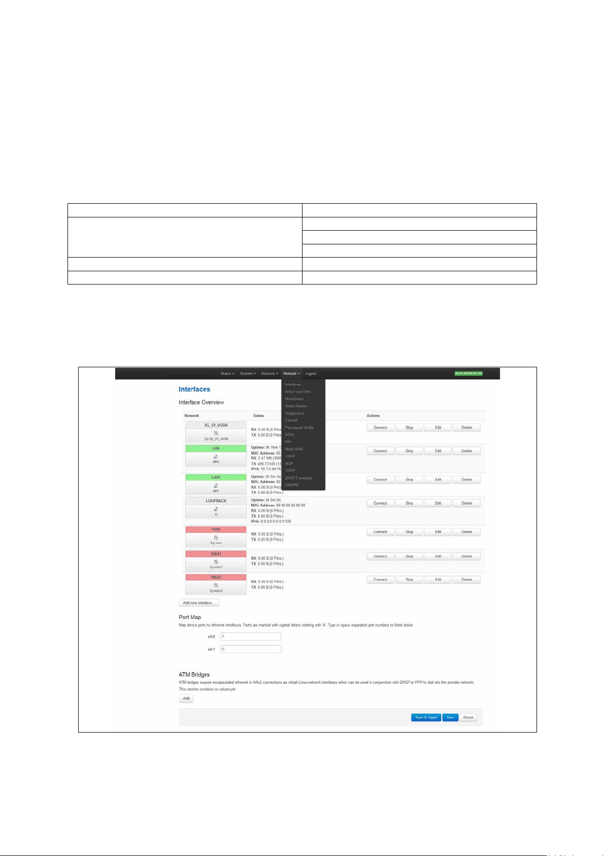
_______________________________________________________________________________________________________
Package
Sections
interface
route
alias
firewall
zone
dhcp
dhcp
11: Configuring an Ethernet interface on a GW1000 router
11 Configuring an Ethernet interface on a GW1000 router
This section describes how to configure an Ethernet interface on a GW1000 or GW1000M
router, including configuring the interface as a DHCP server, adding the interface to a
firewall zone and mapping the physical switch ports.
11.1 Configuration packages used
network
11.2 Configuring an Ethernet interface using the web interface
To create and edit interfaces via the web interface, in the top menu, click Network ->
Interfaces. The Interfaces overview page appears.
Figure 48: The interfaces overview page
_______________________________________________________________________________________________________
© Virtual Access 2018
GW1000 Series User Manual
Issue: 2.3 Page 90 of 463
Page 91

_______________________________________________________________________________________________________
Section
Description
interfaces here.
into the provider network.
11: Configuring an Ethernet interface on a GW1000 router
There are two sections in the Interfaces page.
Interface Overview Shows existing interfaces and their status. You can create new and edit existing
ATM Bridges ATM brid ges expose enca p s ulated Ethe r ne t in AAL5 co nnectio ns as v irtual Linux
network interfaces, which can be used in conjunction with DHCP or PPP to dial
11.3 Interface overview: editing an existing interface
To edit an existing interface, from the interface tabs at the top of the page, select the
interface you wish to configure. Alternatively, click Edit in the interface’s row.
11.3.1 Interface overview: creating a new interface
To create a new interface, in the Interface Overview section, click Add new interface.
The Create Interface page appears.
_______________________________________________________________________________________________________
© Virtual Access 2018
GW1000 Series User Manual
Issue: 2.3 Page 91 of 463
Figure 49: The create interface page
Page 92

_______________________________________________________________________________________________________
Web Field/UCI/Packag e Optio n
Description
Allowed characters are A-Z, a-z, 0-9 and _
Web
Description
UCI
address and netmask.
assigned by DHCP.
Unmanaged
Unspecified
none
(RFC4213)
IPv4
transport.
protocol.
IOT
IOT
iot
L2TP
Layer 2 Tunnelling Protocol
l2tp
L2TPv3
L2TPv3 Tunnelling Protocol
l2tpv3
PPP
Point to Point Protocol
ppp
Protocol
PPPoE
PPP over Ethernet
pppoe
PPPoATM
PPP over ATM
pppoa
modem.
Modem)
Empty
interfaces.
e.g. option ifname ‘eth2 eth3’.
Section
Description
custom DNS servers, MTU and firewall configuration.
IP-Aliases
Assigning multiple IP addresses to the inte rf ac e .
DHCP Server
Configuring DHCP server settings for this inte rface.
11: Configuring an Ethernet interface on a GW1000 router
Web: Name of the new interface
UCI: network.<if name>
Opt: config interface
Web: Protocol of the new interface
UCI: network.<if name>.proto
Opt: proto
Assigns a logical name to the interface. The network inter f ace
section will assign this name (<if name>).
Type the name of the new interface.
Specifies what protocol the inter f ace will ope rate on. Select
Static.
Static Static configur ation with fixed
DHCP Client Address and netmask are
IPv6-in-IPv4
IPv6-over-
Used with tunnel brokers.
Stateless IPv6 over IPv4
GRE Generic Routing Encapsulation
PPtP Point to Po int T unne lling
static
dhcp
gre
pptp
Web: Create a bridge over multiple
interfaces
UCI: network.<if name>.type
LTE/UMTS/
GPRS/EV-DO
PPP(PSTN-
If you select this option the new logical interface create d will act
as a bridging interface between the chosen existing physical
interfaces.
CDMA, UMTS or GPRS
3g
connection using an AT-style 3G
PPP v90 modem pppmodem
Opt: type
Bridge Configures a bridge over multiple
Web: Cover the following interface
UCI: network.<if name>.ifname
Opt: ifname
Physical interface name to assign to this log ic a l inte rf ac e . If
creating a bridge over multiple interfaces select two interfaces to
bridge. When using uci, seperate the interface names by a space
Table 21: Information table for the create new interface page
Click Submit. The Interface configuration page appears. There are three sections:
Common Configuration Conf igure the interface settings such as protocol, IP address, gateway, netmask,
_______________________________________________________________________________________________________
© Virtual Access 2018
GW1000 Series User Manual
Issue: 2.3 Page 92 of 463
Page 93
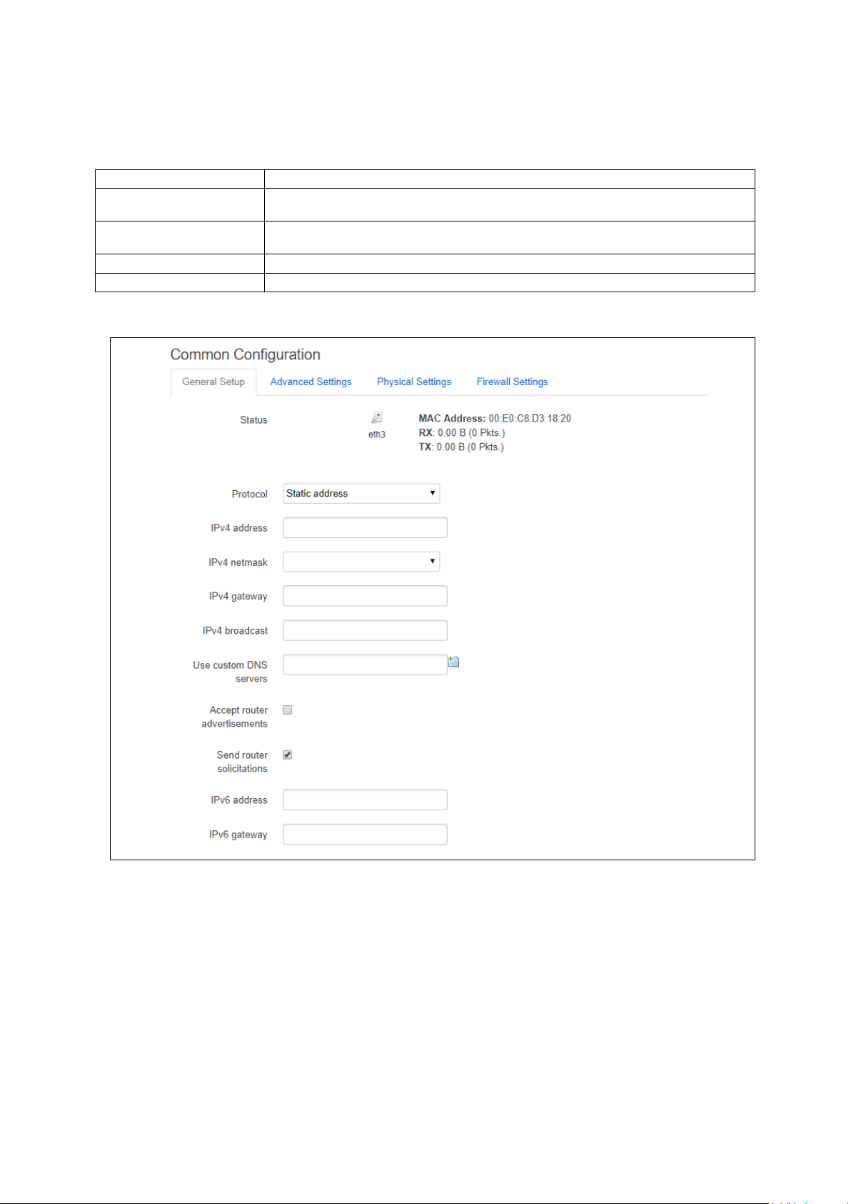
_______________________________________________________________________________________________________
Section
Description
netmask, custom DNS servers.
and 'Use gateway metric'.
Physical Settings
Bridge interfaces, VLAN PCP to SKB priority mapping.
Firewall settings
Assign a firewall zone to the interface.
11: Configuring an Ethernet interface on a GW1000 router
11.3.2 Interface overview: common configuration
The common configuration section has four sub sections:
General Setup Configure the basic interface settings s uc h as proto col, IP a ddress, gateway,
Advanced Settings 'Bring up on boot', 'Monitor interface state', Overr id e MAC addre s s , Overr id e MTU
11.3.2.1 Common configuration – general setup
Figure 50: The Ethernet connection common configuration settings page
_______________________________________________________________________________________________________
© Virtual Access 2018
GW1000 Series User Manual
Issue: 2.3 Page 93 of 463
Page 94

_______________________________________________________________________________________________________
Web Field/UCI/Packag e Optio n
Description
Web: status
Shows the current status of the interface.
Web
Description
UCI
address and netmask.
assigned by DHCP.
Unmanaged
Unspecified
none
(RFC4213)
IPv4
transport.
protocol
IOT
IOT
iot
L2TP
Layer 2 Tunnelling Protocol.
l2tp
L2TPv3
L2TPv3 Tunnelling Protocol
l2tpv3
PPP
Point to Point Protocol.
ppp
Protocol.
PPPoE
PPP over Ethernet
pppoe
PPPoATM
PPP over ATM
pppoa
modem.
Modem)
Opt: ipaddr
Opt: netmask
Opt: gateway
Opt: broadcast
Opt: dns
Opt: accept_ra
Opt:send_rs
Opt: ip6addr
11: Configuring an Ethernet interface on a GW1000 router
Web:Protocol
UCI: nework.<if name>.proto
Opt:proto
Protocol type. The interface protocol may be one of the options s how n
below. The protocol selected in the previous step w ill be displayed as
default but can be changed if required.
Static Static configuration with fixed
DHCP Client Address and netmask are
IPv6-in-IPv4
IPv6-over-
Used with tunnel brokers.
Stateless IPv6 over IPv4
GRE Generic Routing Encapsulation
PPtP Point to Po int T unne lling
LTE/UMTS/
GPRS/EV-DO
CDMA, UMTS or GPRS
connection using an AT-style 3G
static
dhcp
gre
pptp
3g
Web: IPv4 address
UCI: network.<if name>.ipaddr
Web:IPv4 netmask
UCI: network.<if name> .netmask
Web:IPv4 gateway
UCI: network.<if name> .gateway
Web:IPv4 broadcast
UCI: network.<if name> .broadcast
Web:Use custom DNS servers
UCI: network.<if name> .dns
Web:Accept router advertisements
UCI: network.<if name> .accept_ra
Web:Send router solicitations
UCI: network.<if name>
Web:IPv6 address
UCI: network.<if name> .ip6addr
PPP(PSTN-
PPP v90 modem pppmodem
The IPv4 address of the interface. This is optional if an IPv6 address is
provided.
Subnet mask to be applied to the IP address of this interface.
IPv4 default gateway to assign to this interfac e (optio na l).
Broadcast address. This is automaticall y gene rated if no broadcast
address is specified.
List of DNS server IP addresses (op tio na l). Multip le DNS Servers are
separated by a space when using UCI or CLI.
Specifies whether to accept IPv6 Router Adver tis e m e nts on this
interface (optional).
Note: default is 1 if protocol is set to DHCP, otherwise defaults to 0.
Specifies whether to send Router Soliticitations on this interface
(optional).
Note: defaults to 1 for static protocol, otherwis e defa ults to 0.
The IPv6 IP address if the interface. Optional if an IPv4 address is
provided.
CIDR notation for the IPv6 address is required.
_______________________________________________________________________________________________________
© Virtual Access 2018
GW1000 Series User Manual
Issue: 2.3 Page 94 of 463
Page 95
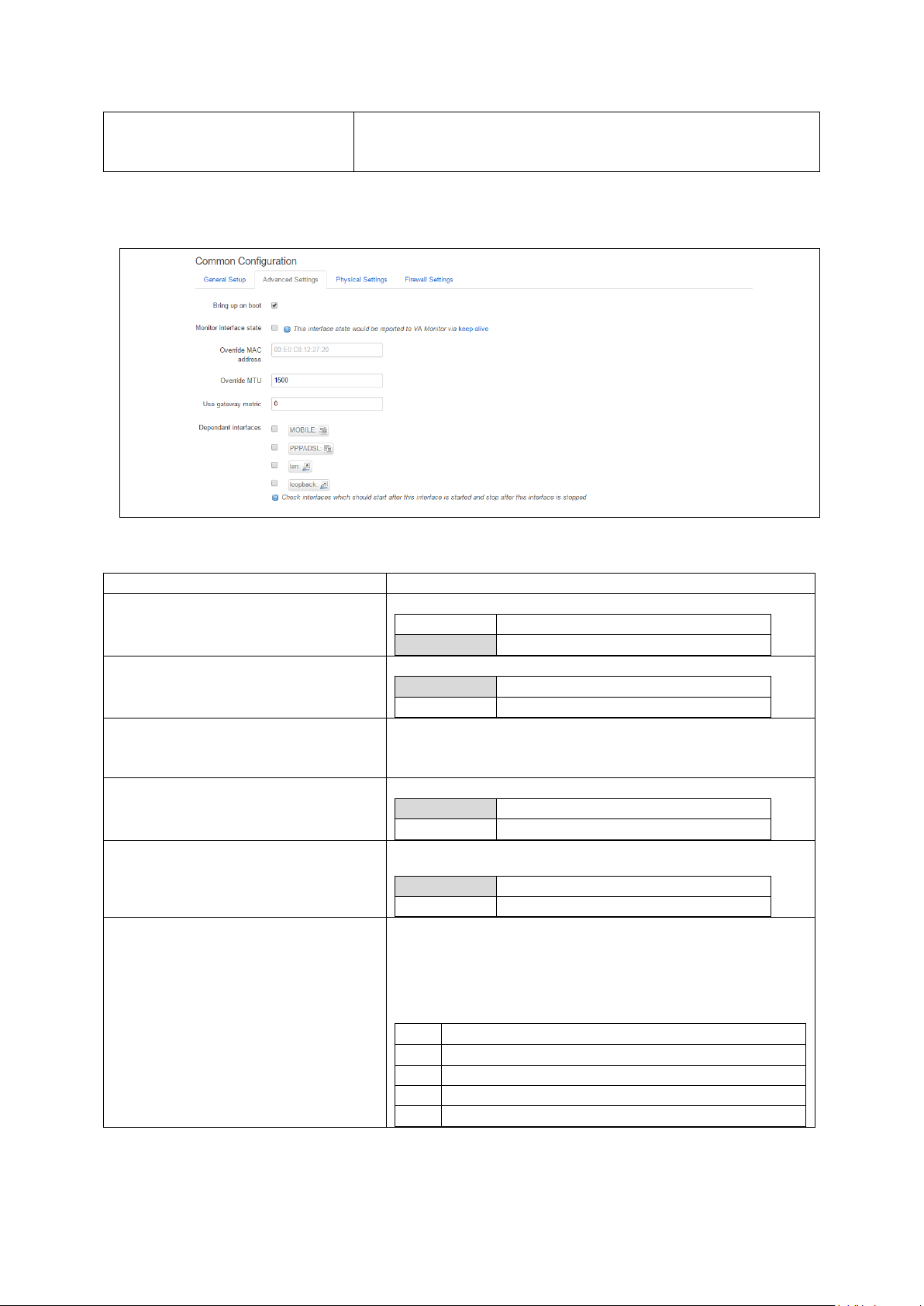
_______________________________________________________________________________________________________
Opt:ip6gw
Web Field/UCI/Packag e Optio n
Description
Opt: auto
0
Disabled.
1
Enabled.
0
Disabled.
1
Enabled.
Opt: macaddr
the form: hh:hh:hh:hh:hh:hh, where h is a hexadec imal number.
Opt: mtu
1500
1500 bytes
Range
0 Range
gre
option local_interface
lt2p
option src_ipaddr
iot
option wan1 wan2
6in4
option ipaddr
6to4
option ipaddr
11: Configuring an Ethernet interface on a GW1000 router
Web:IPv6 gateway
Assign given IPv6 default gateway to this interf ace (op tional).
UCI: network.<if name> .ip6gw
Table 22: Information table for LAN interface common configuration settings
11.3.2.2 Common configuration: advanced settings
Figure 51: The Ethernet connection advanced settings page
Web: Bring up on boot
UCI: network.<if name>.auto
Web: Monitor interface state
UCI: network.<if name>.monitored
Opt: monitored
Web: Override MAC address
UCI: network.<if name>.macaddr
Web: Override MTU
UCI: network.<if name>.mtu
Web: Use gateway metric
UCI: network.<if name>.metric
Opt: metric
Web: Dependant Interfaces
UCI: network.[..x..].dependants
Opt: dependants
Enables the interface to connect automatic a lly on boot up.
Enabled if status of interface is presented o n Monito r ing p latform.
Override the MAC address assigned to this interf a c e . Must be in
Defines the value to override the default MTU on this interface.
Specifies the default route metric to use for this interface
(optional).
Lists interfaces that are dependent on this parent interface.
Dependent interfaces will go down when the parent interface is
down and will start or restart when parent interfac e star ts .
Separate multiple interfaces by a space when using UCI.
Example: option dependants ‘PPPADSL MOBILE’
This replaces the following previous options in child interfaces.
_______________________________________________________________________________________________________
© Virtual Access 2018
GW1000 Series User Manual
Issue: 2.3 Page 95 of 463
Page 96

_______________________________________________________________________________________________________
Blank
No SNMP interface alias index
Range
0 - 4294966295
Web Field/UCI/Packag e Optio n
Description
Blank
Bridge
Configures a bridge over multiple interfaces.
0
Disabled.
1
Enabled.
Opt: list vlan_qos_map_ingress
Opt: list vlan_qos_map_egress
name>.ifname=eth2 eth 3
0
Disabled.
1
Enabled.
0
Disabled.
1
Enabled.
11: Configuring an Ethernet interface on a GW1000 router
Web: SNMP Alias ifindex
UCI: network.[..x..].snmp_alias_ifindex
Opt: snmp_alias_ifindex
Defines a static SNMP interface alias ind ex for this inte r face, that
can be polled via the SNMP interface index
(snmp_alias_ifindex+1000). Read the chapter, ‘Configuring
SNMP’ for more information.
Table 23: Information table for common configuration advanced settings
11.3.2.3 Common configuration: physical settings
Figure 52: The common configuration physical settings page
Web: Bridge interfaces
UCI: network.<if name>.type
Opt: type
Web: Enable STP
UCI: network.<if name>.stp
Opt: stp
Web: VLAN PCP to skb>priority mapping
UCI: network.<if
name>.vlan_qos_map_ingress
Web: skb priority to >VLAN PCP mapping
UCI: network.<if
name>.vlan_qos_map_egress
Web: Interface
UCI: network.<if name>.ifname
Opt: ifname
Sets the interface to bridge over a specified interf a ce(s ). The
physical interfaces can be selected from the list and are defined
in network.<if name>.ifname.
Enable Spanning Tree Protocol. This op tio n is only available when
the Bridge Interfaces option is selec ted.
VLAN priority code point to socket buffer mapp ing . Multip l e
priority mappings are entered with a space between the m when
using UCI.
Example: network.<if name>. vlan_qos_ map_ingress =1:2 2:1
Socket buffer to VLAN priority code point mapp ing . Multiple
priority mappings are entered with a space between the m when
using UCI.
Example: network.<if name>. vlan_qos_ map_egr e ss =1:2 2:1
Physical interface to assign the logical interface to. If mapping
multiple interfaces for bridging the inte rf a ce names are separ ated
by a space when using UCI and package options.
Example: option ifname ‘eth2 eth3’ or network.<if
Web: Auto Negotiation
UCI: network.<if name>.autoneg
Opt: autoneg
Web: Full Duplex
UCI: network.<if name>.fullduplex
Opt: fullduplex
_______________________________________________________________________________________________________
© Virtual Access 2018
GW1000 Series User Manual
Issue: 2.3 Page 96 of 463
Specifies if sspeed and duplex mode should be autonegotiated.
Ability to change duplex mode.
Page 97

_______________________________________________________________________________________________________
Opt: speed
Eth1:10,100
Package
Sections
Network
alias
Web Field/UCI/Packag e Optio n
Description
Opt: config alias ‘aliasname’
Opt: interface
Opt: proto
11: Configuring an Ethernet interface on a GW1000 router
Web: Ethernet Speed
UCI: network.<if name>.speed
Sets Ethernet speed. Available optio ns are :
Eth0:10,100,1000
Table 24: Information table for physical settings page
11.3.2.4 Common configuration: firewall settings
Use this section to select the firewall zone you want to a ss ign to this interface.
Select unspecified to remove the interface from the associated zone or fill out the create
field to define a new zone and attach the interface to it.
Figure 53: GRE firewall settings
11.3.3 Interface overview: IP-aliases
IP aliasing is associating more than one IP address to a network interface. You can
assign multiple aliases.
11.3.3.1 IP-alias packages used
11.3.3.2 Configuring IP-alias using the web
To use IP-Aliases, enter a name for the alias and click Add. This name will be assigned
to the alias section for this IP-alias. In this example the name ethalias1 is used.
Figure 54: The IP-Aliases section
UCI: network.<alias name>=alias
UCI: network.<alias name>.inter f a c e
UCI: network.<alias name>.proto
_______________________________________________________________________________________________________
© Virtual Access 2018
GW1000 Series User Manual
Issue: 2.3 Page 97 of 463
Assigns the alias name.
This maps the IP-Alias to the interface.
This maps the interface protocol to the alias.
Table 25: Information table for IP-Aliases name assignment
Page 98

_______________________________________________________________________________________________________
Web Field/UCI/Packag e Optio n
Description
Opt: ipaddr
Opt: netmask
Opt: gateway
Web Field/UCI/Packag e Optio n
Description
Opt: bcast
Opt: dns
After you click Add, the IP Aliases configuration options page appears. The IP-Aliases
page is divided into two sub sections: General Setup and Advanced Settings.
11.3.3.3 IP-aliases: general setup
Figure 55: The IP-aliases general setup section
11: Configuring an Ethernet interface on a GW1000 router
Web: IPv4-Address
UCI: network.<alias name>.ipad dr
Web: IPv4-Netmask
UCI: network.<alias name>.netmas k
Web: IPv4-Gateway
UCI: network.<alias name>.gateway
Table 26: Information table for IP-Alias general setup page
11.3.3.4 IP-aliases: advanced settings
Defines the IP address for the IP alias.
Defines the netmask for the IP alias.
Defines the gateway for the IP alias.
Web: IPv4-Broadcast
UCI: network.<alias name>.bcast
Web: DNS-Server
UCI: network.<alias name>.dns
_______________________________________________________________________________________________________
© Virtual Access 2018
GW1000 Series User Manual
Issue: 2.3 Page 98 of 463
Figure 56: The IP-Aliases advanced settings section
Defines the IP broadcast address for the IP alias.
Defines the DNS server for the IP alias.
Table 27: Information table for IP-Alias advanced settings page
Page 99

_______________________________________________________________________________________________________
Package
Sections
dhcp
dhcp
Web Field/UCI/Packag e Optio n
Description
0
Disabled.
1
Enabled.
Web
Description
UCI
DHCPv4
DHCP for IPv4
ipv4
DHCPv6
DHCP for IPv6
ipv6_dhcp
Advertisements
Delegation
11.3.4 Interface overview: DHCP server
11.3.4.1 DHCP server: packages used
To assign a DHCP Server to the interface, uncheck the Ignore Interf ace box.
Figure 57: The DHCP Server settings section
The DHCP Server configuration options will appear. The DHCP Server section is divided
into two sub sections: General Setup and Advanced Settings.
11: Configuring an Ethernet interface on a GW1000 router
11.3.4.2 DHCP server: general setup
Figure 58: The DHCP server general setup section
Web: Ignore interface
UCI: dhcp.@dhcp[x].ignore
Opt: ignore
Defines whether the DHCP pool should be enabled for this
interface. If not specified for the DHCP pool then defa ult is disab le d
i.e. dhcp pool enabled.
Web: Mode
UCI: dhcp.@dhcp[x].mode
Opt: mode
_______________________________________________________________________________________________________
© Virtual Access 2018
GW1000 Series User Manual
Issue: 2.3 Page 99 of 463
Defines whether the DHCP pool should be enabled for this
interface. If not specified for the DHCP pool then defa ult is disab le d
i.e. dhcp pool enabled.
IPv6 Router
DHCPv6 Prefix
IPv6 RA ipv6_ra
DHCPv6 prefix delegation ipv6_pd
Page 100

_______________________________________________________________________________________________________
100 Range
150 Range
0 – 255
12h
12 hours
Range
lan Range
Web Field/UCI/Packag e Optio n
Description
1
Dynamically allocate leases.
leases.
0
Disabled.
1
Enabled.
11: Configuring an Ethernet interface on a GW1000 router
Web: Start
UCI: dhcp.@dhcp[x].start
Opt: start
Web: Limit
UCI: dhcp.@dhcp[x].limit
Opt: limit
Web: leasetime
UCI: dhcp.@dhcp[x].leaseti me
Opt: leasetime
Web: n/a
UCI: dhcp.@dhcp[x].interface
Opt: interface
Defines the offset from the network address for the star t of the
DHCP pool.
Example: for network a ddress 192.168.100.10/24, start=100,
DHCP allocation pool will start at 192.168 .100 .10 0.
For subnets greater than /24, it may be greater than 255 to span
subnets. Alternatively , spe c ify in IP addre s s notation using the
wildcard ‘0’ where the octet is required to inheri t bits from the
interface IP addess.
Example: to define a DHCP scope starting from 10.1.20.0 on an
interface with 10.1.0.0/16 address , set s tart to 0.0.20.1
Defines the size of the address pool.
Example: for network address 192.168.100.10/24, start=100,
limit=150, DHCP allocation pool will be .100 to .249
Defines the lease time of addresses handed out to clients, for
example 12h or 30m.
Defines the interface that is served by this DHCP pool. This must
be one of the configured interfaces.
When configured through the web UI this will be automatic ally
populated with the interface name.
Table 28: Information table for DHCP server general setup page
11.3.4.3 DHCP Server: advanced settings
Figure 59: The DHCP server advanced settings section
Web: Dynamic DHCP
UCI: dhcp.@dhcp[x].dynamicdhcp
Opt: dynamicdhcp
Web: Force
UCI: dhcp.@dhcp[x].force
Opt: force
Defines whether to dynamically allocate DHCP leases.
0 Use /etc/ethers file for serving DHCP
Forces DHCP serving on the specified interf ac e even if another
DHCP server is detected on the same network segment.
_______________________________________________________________________________________________________
© Virtual Access 2018
GW1000 Series User Manual
Issue: 2.3 Page 100 of 463
 Loading...