

Virtium VSFA25, StorFly 25PE Product Manual
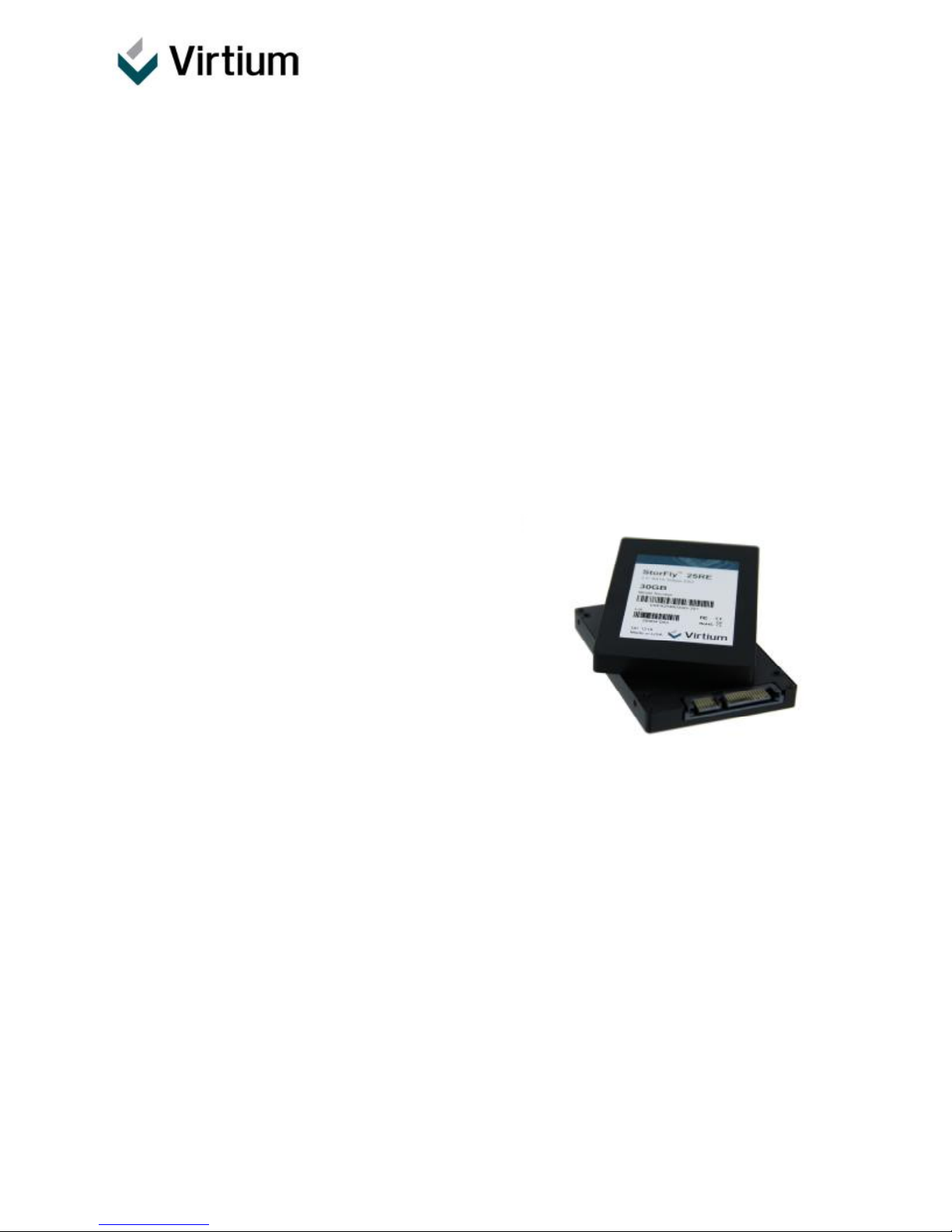
Virtium StorFly™ 25PE – 2.5” SATA 3Gbps SSD
VSFA25 Product Manual
____________________________________________________________________________________
1.0 Introduction
Virtium’s StorFly™ 25 is solid state drive (SSD) technology designed for the unique capacity, workload
and product lifecycle requirements of a broad range of embedded systems including networking,
industrial automation, medical and gaming equipment as well as point-of-sale terminals, military data
recorders and wearable computers. StorFly™ 25 SSDs deliver stable configuration for long product life
and eliminate the need for frequent product re-qualifications. StorFly™ 25PE SSDs are designed for
optimum performance at low to moderate capacity points and are excellent solutions for write intensive
applications.
1.1 Features
• Capacities: 8, 16, 32, 64, 128GB
• Sequential performance (128GB)
o Read/write: 270.220 MB/s
• Random Performance (128GB)
o Read/write IOPS: 15K/4K
• Latency:
o Read/write (μs): TBD/TBD
• Temperature
o Commercial operating: 0oC to 70oC
o Industrial operating: -40oC to +85oC
o Non-operating: -55oC to +95oC
• Power
• Reliability
• S.M.A.R.T. attribute reporting
• Compliance
(1) Measured based on 70/30 random read/write. Power is vary depending upon capacities, see section 4.5 for completed
(1)
(128GB; 5V)
o Typical: 1.2W
o Idle: 1.07W
o UBER: 1 error per 1014 bits read
o MTBF: 2,000,000 hours
o Endurance: Upto 600 TBW (128GB)
o SAT revision 2.6 (SATA 3Gbps and
1.5Gbps)
o ATA/ATAPI-7
o FCC, CE, UL, RoHS
typical and maximum power measurement per capacities
• Mechanical Dimensions - L x W x H mm (in.)
o 100.5 (3.96) x 69.85 (2.75) x 9.5 (0.37)
• Weight
o 87 +/- 2 g (128GB)
• Environmental (Operating/non-operating):
o Shock: 50G (11ms/Axis) x 3 Axes
o Vibration: 10 to 2000 Hz, 16.4G, 3 Axes
o Altitude: 40000 feet
o Humidity: 95%
Product Specification
Capacity
Operating Temperature
Interface/Form Factor
Class
Virtium proprietary
StorFly 25
VSFA25PxxxxG-xxx
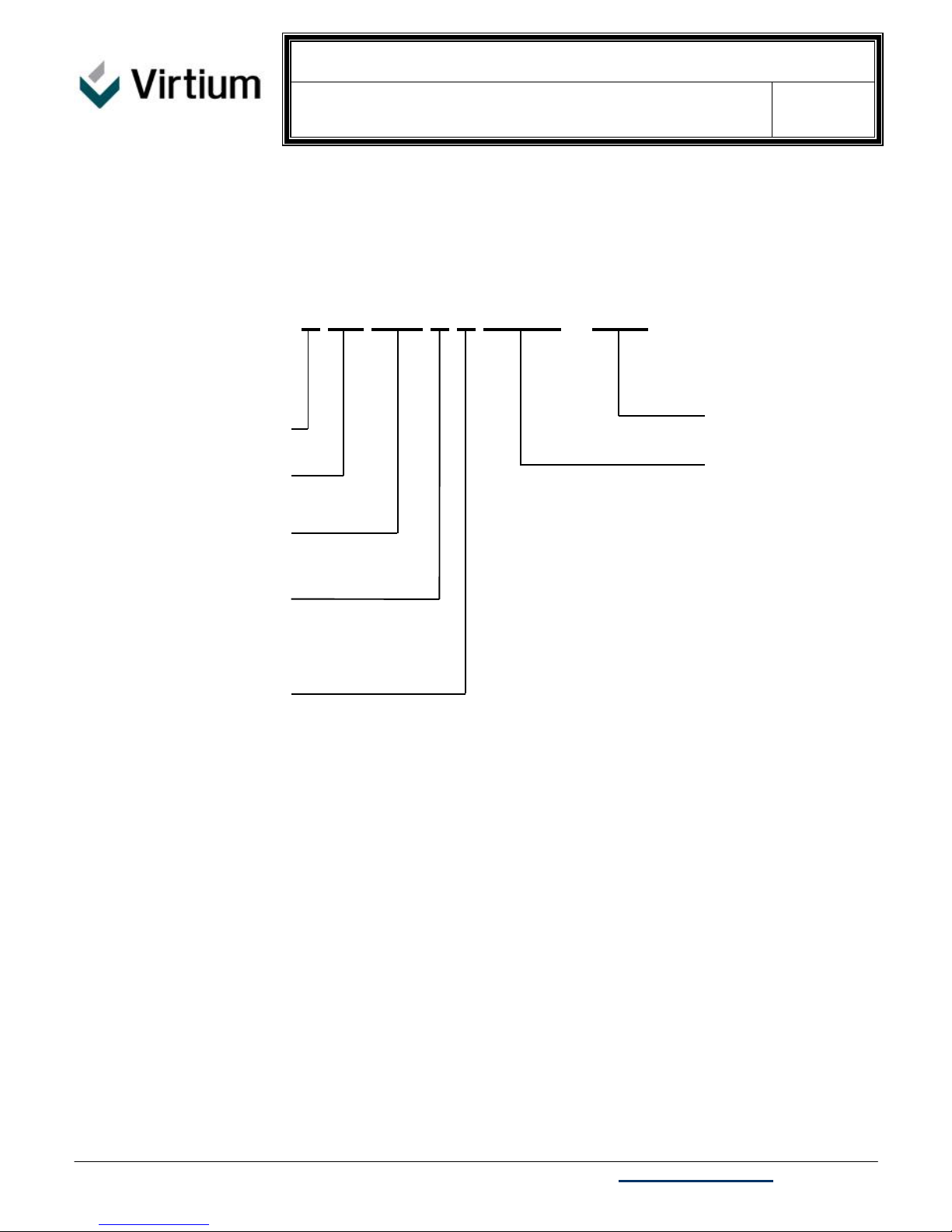
2.0 Ordering Information and Part Numbering System
Virtium
StorFly
25: 2.5”, 9.5mm SSD
P = PE
C: 0oC to 70oC
I: -40oC to 85oC
V SF A25 P X XXXG – XXX
Rev: 1.0
008G: 8GB
016G: 16GB
032G: 32GB
064G: 64GB
128G: 128GB
Tel 949.888.2444 – 30052 Tomas, Rancho Santa Margarita, CA 92688 USA – www.virtium.com 2

Product Specification
StorFly 25
VSFA25PxxxxG-xxx
Rev: 1.0
3.0 Table of Contents
1.0 INTRODUCTION................................................................................................................................................1
2.0 ORDERING INFORMATION AND PART NUMBERING SYSTEM....................................................................2
3.0 TABLE OF CONTENTS......................................................................................................................................3
4.0 SPECIFICATIONS..............................................................................................................................................5
4.1 Capacity..............................................................................................................................................................5
4.2 Performance.......................................................................................................................................................5
4.3 Environmental Specifications..............................................................................................................................5
4.3.1 Temperature Range.......................................................................................................................................5
4.3.2 Humidity..........................................................................................................................................................6
4.3.3 Shock and Vibration.......................................................................................................................................6
4.4 System Reliability...............................................................................................................................................6
4.4.1 Power Consumption.......................................................................................................................................7
4.5 Power Requirements..........................................................................................................................................7
4.6 FCC and CE Requirements................................................................................................................................7
4.7 ROHS COMPLIANCE.........................................................................................................................................7
5.0 PHYSICAL SPECIFICATION.............................................................................................................................8
5.1 Pin Assignments.................................................................................................................................................8
5.2 MECHANICAL DIMENSIONS..........................................................................................................................10
6.0 ATA COMMANDS............................................................................................................................................11
6.1 Supported Commands......................................................................................................................................11
6.2 Identify Device Data..........................................................................................................................................14
6.3 Device Overlay Data Structure.........................................................................................................................21
6.4 S.M.A.R.T. ATTRIBUTES.................................................................................................................................22
7.0 REFERENCES.................................................................................................................................................28
8.0 REVISION HISTORY........................................................................................................................................29
Tel 949.888.2444 – 30052 Tomas, Rancho Santa Margarita, CA 92688 USA – www.virtium.com 3
Product Specification
StorFly 25
VSFA25PxxxxG-xxx
Rev: 1.0
List of Tables
TABLE 1: PRODUCT CAPACITY....................................................................................................................................5
TABLE 2: PERFORMANCE............................................................................................................................................5
TABLE 3: TEMPRATURE RANGE..................................................................................................................................5
TABLE 4: SHOCK AND VIBRATION...............................................................................................................................6
TABLE 5: SYSTEM RELIABILITY...................................................................................................................................6
TABLE 6: MEAN TIME BETWEEN FAILURES (MTBF)..................................................................................................7
TABLE 7: POWER CONSUMPTION...............................................................................................................................7
TABLE 8: PIN ASSIGNMENTS.......................................................................................................................................8
TABLE 9: SUPPORTED ATA COMMANDS.................................................................................................................11
TABLE 10: POWER MANAGEMENT COMMANDS.....................................................................................................11
TABLE 11: SECURITY COMMANDS............................................................................................................................12
TABLE 12: SMART COMMANDS.................................................................................................................................12
TABLE 13: _____ COMMANDS....................................................................................................................................12
TABLE 14: 48-BIT ADDRESS FEATURE SET COMMANDS.......................................................................................13
TABLE 15: NATIVE COMMAND QUEUING.................................................................................................................13
TABLE 16: OTHER COMMAND....................................................................................................................................13
TABLE 17: EXECUTE DEVICE DIAGNOSTIC COMMAND INPUTS...........................................................................14
TABLE 18: EXECUTE DEVICE DIAGNOSTIC COMMAND INPUTS...........................................................................21
TABLE 19: SMART FEATURE REGISTER VALUES...................................................................................................22
TABLE 20: SMART DATA STRUCTURE......................................................................................................................23
TABLE 21: SMART ATTRIBUTE DEFINATIONS.........................................................................................................24
TABLE 22: BYTES 2-361 INDIVIDUAL ATTRIBUTE DATA.........................................................................................25
TABLE 23: SMART READ ATTRIBUTE THRESHOLD COMMAND............................................................................26
TABLE 24: THRESHOLD VALUES...............................................................................................................................26
TABLE 25: SMART EXECUTE OFF-LINE IMMEDIATE LBA LOW REGISTER VALUES...........................................27
List of Figures
FIGURE 1: SIGNAL SEGMENT AND POWER SEGMENT............................................................................................8
FIGURE 2: MECHANICAL DIMENSIONS.....................................................................................................................10
Tel 949.888.2444 – 30052 Tomas, Rancho Santa Margarita, CA 92688 USA – www.virtium.com 4
Product Specification
4.0 Specifications
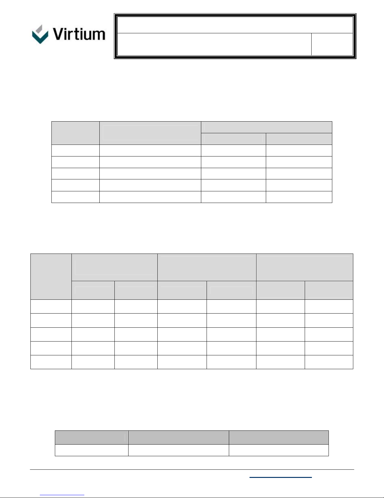
4.1 Capacity
Advertised
Capacities
(GB)
8 15,458,304 7,914,651,648 7.37
16 31,358,976 16,055,795,712 14.95
32 62,717,952 32,111,591,424 29.90
64 125,435,904 64,223,182,848 59.81
128 250,871,808 128,446,365,696 119.63
(1) LBA: Logical Block Address. Logical block size of 512 bytes
Table 1: Product capacity
User-Addressable
LBA(1)
StorFly 25
VSFA25PxxxxG-xxx
User-Addressable Capacities
Bytes GBytes
Rev: 1.0
4.2 Performance
Table 2: Performance
THROUGH-PUT
Capacities
(GB)
8
16
32
64
128
64KB file, QD=32
Read Seq Write Seq Read Random Write Random
4KB file, Queue Depth=32,
IOPS
100% Random
4KB file, Queue Depth=32,
70% Read, 30% Write
Read
Random
4.3 Environmental Specifications
4.3.1 Temperature Range
IOPS
Write
Random
P/N Operating Temparature (0C) Storage Temperature (0C)
VSFA25PCxxxG-xxx 0°C to 70oC -55°C to +95°C
Tel 949.888.2444 – 30052 Tomas, Rancho Santa Margarita, CA 92688 USA – www.virtium.com 5
Table 3: Temprature range
Product Specification
VSFA25PIxxxG-xxx -40°C to 85oC -55°C to +95°C
4.3.2 Humidity
Relative Humidity: 5-95%, non-condensing
4.3.3 Shock and Vibration
Reliability Test Conditions
Vibration ???G, ??? MIL-STD-810F, Method ???, Procedure ?
Mechanical Shock ???G, ??? MIL-STD-810F, Method ???, Procedure ?
Altitude ???G, ??? MIL-STD-810F, Method ???, Procedure ?
Table 4: Shock and Vibration
StorFly 25
VSFA25PxxxxG-xxx
Rev: 1.0
4.4 System Reliability
Capacities (GB) TBW(1) GB/day for 5 yrs. Services Life
8
16
32
64
128
(1) TBW specifications are in accordance with JEDEC SSD standard JESD218, JESD219. The values measured at 250C
ambient temperature. Actual resulte will vary depending application usage model
Table 5: System Reliability
Tel 949.888.2444 – 30052 Tomas, Rancho Santa Margarita, CA 92688 USA – www.virtium.com 6
Product Specification
4.4.1 Power Consumption
Table 6: Mean Time Between Failures (MTBF)
Capacities (GB) MTBF(1)
(1) MTBF specification is in accordance with Telcordia SR-332. The
values estimated at 250C ambient temperature.
4.5 Power Requirements
StorFly 25
VSFA25PxxxxG-xxx
8
16
32
64
128
Rev: 1.0
5V (±10%) single power supply operation
Table 7: Power Consumption
Capacties (GB)
8
16
32
64
128
(1) Power measured based on 70/30 random R/W workload (IOMeter 2006)
Sustained Write
(Watts)
Sustained Read
(Watts)
4.6 FCC and CE Requirements
StorFly 25 products conform to CE and FCC requirements. Class: FCC Part 15 Subpart B Class B:2011
4.7 RoHS Compliance
StorFly 25 products are compliant with the ROHS directive.
Typical(1)
(Watts)
Idle
(Watts)
Tel 949.888.2444 – 30052 Tomas, Rancho Santa Margarita, CA 92688 USA – www.virtium.com 7

Product Specification
5.0 Physical Specification
5.1 Pin Assignments
Table 8: Pin Assignments
Name Type Description
S1 GND Ground
S2 Rx+
S3 RxS4 GND Ground
S5 TxS6 Tx+
S7 GND Ground
Key Key Key
Power Pin Assignments
Key Key Key
P1 V33 No Connect
P2 V33 No Connect
P3 V33 No Connect
P4 GND Ground
P5 GND Ground
P6 GND Ground
P7 V5 5V Power, Pre-Charge
P8 V5 5V Power
P9 V5 5V Power
P10 GND Ground
P11 DAS/DSS Device Active Signal/Disable Staggered Spinup
P12 GND Ground
P13 V12 No Connect
P14 V12 No Connect
P15 V12 No Connect
Figure 1: Signal Segment and Power Segment
StorFly 25
VSFA25PxxxxG-xxx
Differential Receive Signal
Differential Transmit Signal
Rev: 1.0
Tel 949.888.2444 – 30052 Tomas, Rancho Santa Margarita, CA 92688 USA – www.virtium.com 8
P15
P1
S1S7

Product Specification
StorFly 25
VSFA25PxxxxG-xxx
Rev: 1.0
Tel 949.888.2444 – 30052 Tomas, Rancho Santa Margarita, CA 92688 USA – www.virtium.com 9
 Loading...