

Viqua VH200, VP600, VH410, VP950, VH410M Owner's Manual
...
Models:
Owner’s Manual
Powered by
VH200, VH410, VP600, VP950
VH410M, VP600M, VP950M
425 Clair Rd. W, Guelph, Ontario, Canada N1L 1R1
t. (+1) 519.763.1032 • f. (+1) 800.265.7246 (US and Canada only)
t. (+31) 73 747 0144 (Europe only) • f. (+1) 519.763.5069
e-mail: info@viqua.com
www.viqua.com
520110_RevL
Congratulations on the purchase of your ultraviolet (UV) water disinfection
system! This system uses the most advanced UV technology on the market and is
designed to provide you with years of trouble free operation with minimal maintenance
required to protect your drinking water from microbiological contaminants.
To ensure ongoing disinfection of your water, UV lamps need to be replaced annually
with VIQUA factory-supplied replacements. VIQUA lamps are the result of extensive
development resulting in a highly efficient disinfection platform with extremely stable UV
output over the entire 9000 hour lifetime. Its success has led to a proliferation of
non-genuine copies in the market.
The UV lamp is the heart of the disinfection system, and there should be no compromise
when it's time for a replacement.
Why should you insist on genuine factory supplied VIQUA replacement lamps?
• Use of widely available, non-genuine, replacement lamps has been shown to damage
the control module of VIQUA UV disinfection equipment.
• An increasing number of calls to VIQUA Technical Support are connected with
non-genuine lamps being used (unknowingly) as replacements.
• Damage arising from the use of non-genuine lamps poses a safety risk and is not
covered by equipment warranty.
• Unless the UV equipment is equipped with a UV sensor (monitor), it is not possible to
verify the UV (invisible) output of replacement lamps.
• Similar appearance to the original lamp and the presence of (visible) blue light does
not mean equivalent disinfection performance.
• VIQUA replacement lamps undergo rigorous performance testing and strict quality
control processes to ensure that the safety and performance certifications of the
original equipment are not compromised.
So, you can see that it's simply not worth the risk! Insist on genuine VIQUA replacement
lamps.
2

Safety Information
Hg
UV
Cu
Section 1 Safety Information
Please read this entire manual before operating this equipment. Pay attention to all dange r , warning, an d caution statements
in this manual. Failure to do so could result in serious personal injury or damage to the equipment.
Make sure that the protection provided by this equipment is not impaired. DO NOT use or install this equipment in any
manner other than that specified in the installation manual.
1.1 Potential Hazards:
Read all labels and tags attached to the system. Personal injury or damage to the system could occur if not observed.
Waste electrical and electronic equipment (WEEE). This symbol
indicates that you should not discard wasted electrical or electronic
equipment (WEEE) in the trash. For proper disposal, contact your
local recycling/reuse or hazardous waste center.
This symbol indicates there is Mercury present.
This is the safety alert symbol. Obey all safety messages that follow
this symbol to avoid potential injury. When on the equipment, refer to
the Operational and Maintenance manual for additional safety
This symbol indicates not to store any combustible or flammable
material close to the system.
This symbol indicates that the contents of the transport package are
fragile and the package should be handled with care.
This symbol indicates safety glasses with side protection is required
for protection against UV exposure.
This symbol indicates a risk of electrical shock and/or electrocution
exists.
This symbol indicates the marked equipment may contain a
component that can eject forcibly. Obey all procedures to safely
depressurize.
This symbol indicates the system is under pressure.
This symbol indicates there is a potential UV hazard. Proper
protection must be worn.
This symbol indicates the marked item could be hot and should not
be touched without care.
This symbol indicates there is a potential for VERY hot water when
flow is started.
Warning: This product may contain chemicals known to the State of California to cause cancer and birth defects or other reproductive harm.
This symbol indicates gloves must be worn.
This symbol indicates safety boots must be worn.
This symbol indicates the operator must read all available
documentation to perform required procedures.
This symbol indicates the plumber must use copper piping.
This symbol indicates that the system should only be connected to a
properly grounded, grounding-type controller receptacle that is
protected by a Ground Fault Circuit Interrupter (GFCI).
1.2 Safety Precautions:
DANGER
Failure to follow these instructions will result in serious injury or death.
• Electric Shock: To avoid possible electric shock, special care should be taken since water is present near the electrical equipment. Unless a
situation is encountered that is explicitly addressed by the provided maintenance and troubleshooting sections, DO NOT attempt repairs yourself,
refer to an authorized service facility.
• GROUNDING: This product must be grounded. If it should malfunction or breakdown, grounding provides a path of least resistance for electric
current to reduce the risk of electrical shock. This system is equipped with a cord having an equipment-grounding conductor and a grounding plug.
The plug must be plugged into an appropriate outlet that is properly installed and grounded in accordance with all local codes and ordinances.
Improper connection of the equipment-grounding conductor can result in a risk of electrocution. Check with a qualified electrician or service
personnel if you are in doubt as to whether the outlet is properly grounded. DO NOT modify the plug provided with this system – if it does not fit in
the outlet, have a proper outlet installed by a qualified electrician. DO NOT use any type of adapter with this system.
• GROUND FAULT CIRCUIT INTERRUPTER PROTECTION: To comply with the National Electrical Code (NFPA 70) and to provide additional
protection from the risk of electric shock, this system should only be connected to a properly grounded, grounding-type controller receptacle that is
protected by a Ground Fault Circuit Interrupter (GFCI). Inspect operation of GFCI as per manufacturer’s suggested maintenance schedule.
• DO NOT operate the disinfection system if it has a damaged cord or plug, if it is malfunctioning or if it has been dropped or damaged in any
manner.
• DO NOT use this disinfection system for other than intended use (potable water applications). The use of attachments not recommended or sold
by the manufacturer / distributor may cause an unsafe condition.
• DO NOT install this disinfection system where it will be exposed to the weather or to temperatures below freezing.
• DO NOT store this disinfection system where it will be exposed to the weather.
• DO NOT store this disinfection system where it will be exposed to temperatures below freezing unless all water has been drained from it and the
water supply has been disconnected.
3
Safety Information
VH200
VH410 y VH410M
VP600 y VP600M
VP950 y VP950M
CAUDAL (gpm de EE. UU.)
E. coli erradicada a 6,6 mJ/cm
2
Cryptosporidium y Giardia lamblia
erradicados a <10 mJ/cm
2
DOSIS UV (FLUENCIA) (MJ/cm2)
Nota: dosis con 95 % de transmisión ultravioleta al
final de la vida útil de la lámpara (EOL)
Servicio de Salud
Pública de
EE. UU. 1966
Estándar del
fabricante
Estándar
NSF/EPA
WA RN IN G
During extended periods of no water flow, the water in your chamber can become very hot (Approx. 60 °C) and potentially lead to scalding. It is
recommended to run your water until this hot water has been purged from your chamber. Do not allow water to contact your skin during this time. To
eliminate this condition, a temperature management valve can be installed at the outlet of your UV system.
CAUTION
Failure to follow these instructions could result in minor or moderate injury.
• Carefully examine the disinfection system after installation. It should not be plugged in if there is water on parts not intended to be wet such as, the
controller or lamp connector.
• Due to thermal expansion concerns and potential material degradation due to UV exposure, it is recommended to use metal fittings and at least 10"
of copper pipe on the outlet of your UV chamber.
NOTICE
• The UV lamp inside the disinfection system is rated at an effective life of approximately 9000 hours. To ensure continuous protection, replace the
UV lamp annually.
• The UV system is not to be used or played with by children. Persons with reduced physical, sensory or mental capabilities, or lack of experience
and knowledge, are also not to handle the UV system unless they have been given supervision or instruction.
• EXTENSION CORDS: If an extension cord is necessary, use only 3-wire extension cords that have 3-prong grounding-type plugs and 3-pole cord
connectors that accept the plug from this system. Use only extension cords that are intended for outdoor use. Use only extension cords having an
electrical rating not less than the rating of the system. A cord rated for less amperes or watts than this system rating may overheat. Exercise caution
when arranging the cord so that it will not be tripped over or pulled. DO NOT use damaged extension cords. Examine extension cord before using
and replace if damaged. DO NOT abuse extension cord. Keep extension cord away from heat and sharp edges. Always disconnect the extension
cord from the receptacle before disconnecting this system from the extension cord. Never yank cord to pull plug from outlet. Always grasp the plug
and pull to disconnect.
• SYSTEM PROTECTION: To protect your Controller, a UL1449 certified (or equivalent) transient voltage surge suppressor is strongly
recommended.
• The UV lamp in this system conforms to the applicable provisions of the Code of Federal Regulations (CFR) requirements including, Title 21,
Chapter 1, Subchapter J, Radiological Health.
• Read and understand the Owner’s Manual before operating and performing any maintenance on this equipment.
1.3 Water Chemistry
Water quality is extremely important for the optimum performance of your UV system. The following levels are
recommended for installation:
Water Quality and Minerals Level
Iron < 0.3 ppm (0.3 mg/L)
Hardness* < 7 gpg (120 mg/L)
Turbidity < 1 NTU
Manganese < 0.05 ppm (0.05 mg/L)
Tannins < 0.1 ppm (0.1 mg/L)
UV Transmittance > 75% (call factory for recommendations on applications where UVT < 75%)
* Where total hardness is less than 7 gpg, the UV unit should operate efficiently provided the quartz sleeve is cleaned
periodically. If total hardness exceeds 7 gpg, the water should be softened. If your water chemistry contains levels in excess
of those mentioned above, proper pre-treatment is re commend ed to corr ect these water prob lems prior to the installation of
your UV disinfection system. These water quality parameters can be tested by your local dealer, or by most private analytical
laboratories. Proper pre-treatment is essential for the UV disinfection system to operate as intended.
4

General Information
2
7
8
9
10
1
3
4
5
6
Section 2 General Information
Figure 1 System Components
Item Description
Temperature management valve
1
(optional)
2 Flow restrictor Optional Used on all systems
3 O-ring 410867 Used on all systems
Open-ended, GE 214 fused quartz
4
sleeve with fire polished ends
®
Hard glass, coated Sterilume
lamps for long, consistent life (9000
5
hours)
6 Retaining Nut RN-001 Used on all systems
-HO UV
Controller (for 100-240V/50-60HZ
7
models only)
IEC replacement power cords for
8
controller (sold separately)
9 Mounting Brackets/Clamp Assembly 410076 Used on all systems
10 UV Sensor 254NM-C1 VH410M, VP600M, VP950M
Part
Number
440179 Optional
QS-001 VH200
QSO-410 VH410, VH410M
QSO-600 VP600, VP600M
QSO-950 VP950, VP950M
S200RL-HO VH200
S410RL-HO VH410, VH410M
S600RL-HO VP600, VP600M
S950RL-HO VP950, VP950M
BA-ICE-CL VH200, VH410
BA-ICE-C VP600, VP950
BA-ICE-CM VH410M, VP600M, VP950M
260010 VH200, VH410, VH410M, VP600, VP600M, VP950, VP950M (N. America)
602637 VH200/2, VH410/2, VH410M/2, VP600/2, VP600M/2, VP950/2, VP950M/2 (EU CEE)
260012
260013
260019 NO CONNECTOR, 3-WIRE, BARE LEADS
VH200/2B, VH410/2B, VH410M/2B, VP600/2B, VP600M/2B, VP950/2B, VP950M/2B
(UK)
VH200/2A, VH410/2A, VH410M/2A, VP600/2A, VP600M/2A, VP950/2A, VP950M/2A
(Australia, NZ)
UV Systems
5
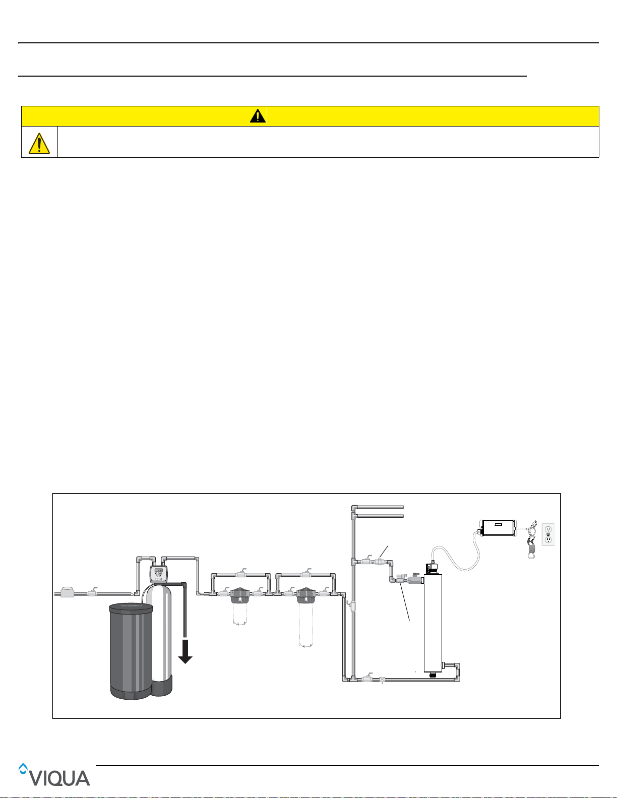
Section 3 Installation
Note: UV system should
be the final piece of
treatment equipment
Optional flow restrictor
Note: Mandatory for
NSF credited systems
Optional water
softener
To
drain
Optional by-pass
assembly
Optional by-pass
assembly
Optional
by-pass
assembly
Optional
solenoid
valve
Hot water pipes
Cold water pipes
Customer supplied
GFCI circuit to
match voltage
Water
meter
Main
water
shut-off
5 Micron
sediment
filter
Optional
carbon
filter
Optional
by-pass
assembly
Optional
drain
cock
3.1 UV Disinfection System
Electronic controller must be connected to a Ground Fault Protected Circuit (GFCI) receptacle and the lamp connector ground wire connected to the
stainless steel chamber.
The disinfection system is designed to be mounte d eit he r horizontally or vertically at the point-of-use or point-of-entr y
depending on the specific flow rate of the unit.
Note: The ideal installation is vertical with the lamp connector on top. This is to prevent water damage from occurring on the
lamp pins and lamp connector.
• The controller should be mounted either above or beside the chamber. Always mount controller horizontally to prevent
moisture from running down cordage and causing a potential fire hazard. Drip loops in all cordage connected to
controller is highly recommended. Refer to Figure 5.
• The complete water system, including any pressure or hot water tanks, must be sterilized before start up by flushing with
chlorine (household bleach) to destroy any residual contamination. Refer to Section 3.2.
• The disinfection system is intended for indoor use only, do not install disinfection system where it may be exposed to the
weather.
Installation
CAUTION
• Install the disinfection system on cold water line only, before any branched lines.
• A 5 micron sediment filter must precede the disinfection system. Ideally, the disinfection system should be the last
treatment the water receives before it reaches the faucet.
Procedure:
1. Figure 2 shows the installation of a typical disinfection system and the related components that may be used for the
installation. The use of a by-pass assembly is recommended in case the system requires “off-line” maintenance. In this
case, note the system requires a supplementary disinfection for the distribution system if any water is used during
by-pass condition. In addition, during by-pass, the water will NOT be disinfected and a “DO NOT CONSUME THE
WATER” tag should be physically installed on the by-pass assembly until such time as the system is sanitized and
returned to service. For more information, refer to Section 3.2. If the water is to be consumed while the system is off-line,
the water must be boiled for twenty minutes prior to consumption.
Figure 2 Disinfection System
Figure 2
6

Installation
2. Select a suitable location for the disinfection system and its related components. As it is recom mended to inst all a GFCI,
make sure that this is taken into consideration prior to any inst allation. The system can either be inst alled vertically (inlet
port at the bottom) as shown in Figure 3 A, or horizontally as shown in Figure 3 B. However, the vertical installation is
the most preferred method. When selecting a mounting location, leave enough space to allow the removal of the UV
lamp and/or quartz sleeve (typically leave a space equal to the size of the chamber itself).
Min. clearance equal
to unit overall length
to unit overall length
Min. clearance equal
Unit overall length
B
Unit overall length
A
Figure 3 Disinfection Installation - Vertical and Horizontal
3. Mount the system to the wall using the supplied clamps. Various connection methods can be used to connect the water
source to the system, however union type connectors are recommended. The use of a flow restrictor device will help to
maintain the manufacturers rated flow. The flow restrictor should be installed on the outlet port and is designed to be
installed in one direction only. Ensure that the flow of the water matches the flow direction as indicated on the flow
restrictor. Refer to Figure 4.
Note: DO NOT solder connections while attached to the system as this could damage the O-ring seals.
Optional temparature
management valve
Flow
Flow
restrictor
Figure 4 Flow Restrictor
4. Mount the VIQUA ICE controller horizontally to the wall, near the chamber. Ideally place the controller above the
chamber and away from any water connection point, to pre vent any water from potentially leaking onto the controller by
means of a leak at a connection point or a “sweating” system. Make sure you allow for a “dri p-loop” as shown in Figure 5
on the lamp, sensor, and power cord, again, to prevent any water from potentially entering the controller.
7
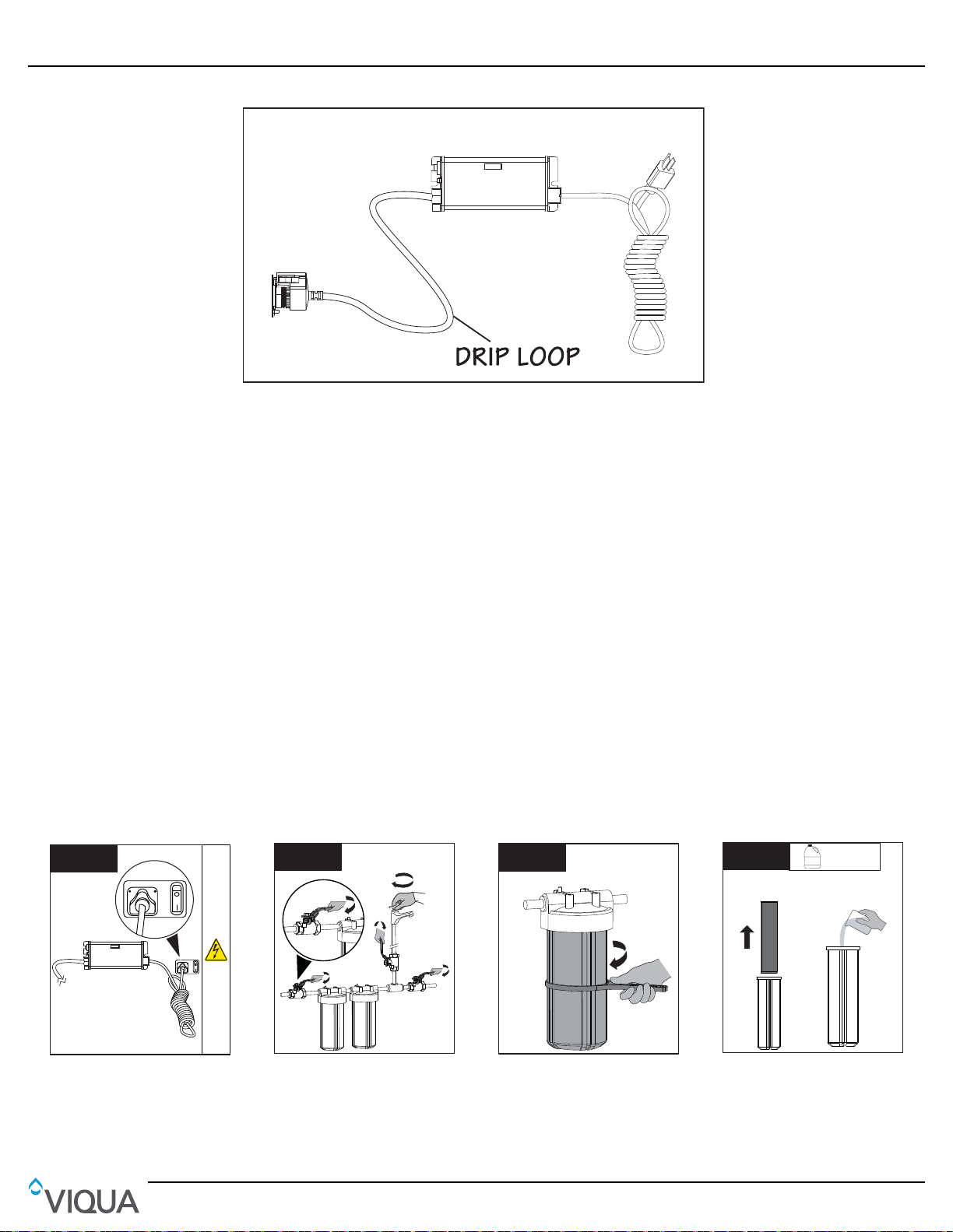
Installation
• Ensure the controller is
plugged in for entire
disinfection process.
1
2
2
1
2
2
2
• Shut off the water supply.
• Close each faucet.
3
• Remove filter cartridge(s).
• Pour 2 cups of household
bleach solution into the filter
housing(s).
Note: DO NOT use Hydrogen
Peroxide.
4
Household 5.25%
Bleach Solution
BLEACH
x2
2
1
Figure 5 Drip Loop
5. Install the UV lamp. Refer to Section 4.1.
6. When all plumbing connections are complete, slowly turn on the water supply and check for leaks. Th e most likely cause
of leaks is from the O-ring seal. In case of a leak, shut water off, drai n cell, remove the ret aining nut, wipe the O-ring and
threads. Clean and re-install.
7. Once it is determined that there are no leaks, plug the system into the ground fault interrupter and check controller to
ensure the system is operating properly. The controller should illuminate without any alarms.
Note: DO NOT look directly at the glowing UV lamp.
8. Allow the water to run for a few minutes to clear any air or dust that may be in the chamber.
Note: When there is no flow, the water in the cell will become warm, as the UV lamp is always on. To remedy this, run a
cold water tap anywhere in the house for a minute to flush out the warm water.
3.2 Disinfection Procedure
UV disinfection is a physical disinfection process and does not add any potentially harmful chemica ls to the water. As UV
does not provide a disinfection residual, it is imperative that the entire distribution system locate d af ter the UV be ch emically
disinfected to ensure that the plumbing system is free from any bacteriological contaminants. The disinfection process must
be performed immediately after the UV unit is installed and repeated thereafter whenever the UV is shut down for service,
without power, or inoperative for any reason. The procedure for sanitizing the plumbing system is readily accomplished as
follows:
8
 Loading...