

Viqua Sterilight S80, Sterilight SM80, Sterilight SV50 Owner's Manual

Owner’s Manual
S80, SM80, SV50
Ultraviolet Water Purification System
Congratulations. By purchasing this system, you
have taken the first step in ensuring safe drinking
water. Designed using the most advanced UV
technology available today, your UV system is
designed to provide you with years of trouble free
operation with minimal maintenance required.
Date of installation:
Installed by:
Installer phone#:
Serial #:
(Found on label on side of Power Supply)
KEY INFORMATION YOU SHOULD KNOW:
• A 5-micron (nominal) sediment filter must be installed upstream
of (before) any UV system.
• This product is for indoor use only. Keep all components clean
and dry.
• Clean the sleeve regularly for optimum performance.
Sterilight® SV50 model is USEPA UVDGM
2006 validated.
425 Clair Road West, Guelph, ON N1L 1R1 Canada
t. 519 763 1032 t.f. 1 800 265 7246 f. 519 763 5069 www.viqua.com
July 2010
P/N 520150-R revD
SAFETY INSTRUCTIONS
GROUNDING
This product must be grounded. If it should malfunction or breakdown, grounding provides a path of least resistance for electric
current to reduce the risk of electrical shock. This system is equipped with a cord having an equipment-grounding conductor and
a grounding plug. The plug must be plugged into an appropriate outlet that is properly installed and grounded in accordance with
all local codes and ordinances.
DANGER – Improper connection of the equipment-grounding conductor can result in a risk of electrocution. Check with a qualified
electrician or service personnel if you are in doubt as to whether the outlet is properly grounded. Do not modify the plug provided
with this system – if it will not fit the outlet, have a proper outlet installed by a qualified electrician. Do not use any type of adapter
with this system.
GROUND FAULT CIRCUIT INTERRUPTER PROTECTION
To comply with the National Electrical Code (NFPA 70) and to provide additional protection from the risk of electric shock, this
system should only be connected to a properly grounded, grounding-type power supply receptacle that is protected by a Ground
Fault Circuit Interrupter (GFCI). Inspect operation of GFCI as per manufacturers suggested maintenance schedule.
EXTENSION CORDS
If an extension cord is necessary, use only 3-wire extension cords that have 3-prong grounding-type plugs and 3-pole cord
connectors that accept the plug from this system. Use only extension cords that are intended for outdoor use. Use only extension
cords having an electrical rating not less than the rating of the system. A cord rated for less amperes or watts than this system
rating may overheat. Exercise caution when arranging the cord so that it will not be tripped over or pulled. Do not use damaged
extension cords. Examine extension cord before using and replace if damaged. Do not abuse extension cord. Keep extension cord
away from heat and sharp edges. Always disconnect the extension cord from the receptacle before disconnecting this system from
the extension cord. Never yank cord to pull plug from outlet. Always grasp the plug and pull to disconnect.
WARNING – To guard against injury, basic safety precautions should be observed, including the following:
1. READ AND FOLLOW ALL SAFETY INSTRUCTIONS.
2. DANGER – To avoid possible electric shock, special care should be taken since water is employed in the use of this system.
Unless a situation is encountered that is explicitly addressed by the provided maintenance and troubleshooting sections,
do not attempt repairs yourself; refer to an authorized service facility.
3. CAUTION - Do not operate with broken or faulty parts as this may result in exposure to ultraviolet radiation. Contact supplier
for replacement parts.
4. Do not operate the system if it has a damaged cord or plug, or if it is malfunctioning or if it has been dropped or damaged in
any manner.
5. Always unplug the system, shut off water flow and release water pressure before servicing or cleaning. Never yank cord to
remove from outlet; grasp the wall plug and pull to disconnect.
6. Do not use the system for other than intended use. The use of attachments not recommended or sold by the manufacturer may
cause an unsafe condition.
7. To prevent risk of electrical shock, connect this system only to a properly grounded, grounding-type power supply receptacle
that is protected by a Ground Fault Circuit Interrupter (GFCI). Inspect performance of GFCI as per manufacturer’s suggested
maintenance schedule. If an extension cord is used, ensure it is of a sufficient rating and accepts the plug from this system;
never use an adapter.
8. Visually inspect this system prior to installation. If the quartz sleeve or lamp is broken, cracked or damaged in any way,
do not use. Contact the supplier for replacement parts
9. Keep all connections dry and off the ground. Do not touch plug with wet hands.
10. The light emitted by the lamp will cause serious eye damage and burn unprotected skin. Do not plug system into an electrical
outlet without first properly securing the lamp into the chamber. Unplug the system prior to removing the lamp from the
chamber.
11. If the UV system malfunctions or fails, water must be boiled prior to consumption until the UV system is operational and the
water lines have been shocked. System failure is indicated by the system’s audible and visual alarms or the absence of any
indicator light.
12. Intended for indoor use only. System must not be exposed to weather elements. In seasonal applications, chamber must be
drained to prevent freezing.
13. Installation of this system must be in accordance with local plumbing and electrical codes as well as any and all applicable
regulations and laws.
14. SAVE THESE INSTRUCTIONS.
WARNING – To prevent risk of electrical shock, connect this system only to a properly grounded,
grounding-type power supply receptacle that is protected by a Ground Fault Circuit Interrupter. Pull
plug before servicing or replacing lamp. Keep all connections dry and off the ground. Do not touch
plug with wet hands.
WARNING – Do not look directly at UV lamp when it is operating. The light emitted by the lamp will
cause serious eye damage and burn unprotected skin.
WARNING – Read manual before installing or servicing this system. Only authorized personnel
possessing a strong understanding of this system should attempt to replace lamp or service this
system.
NOTE – Maximum pressure rating is 100 PSI (6.89 bar)
TABLE OF CONTENTS
Overview 4
Components 4
Specifications 5
Dimensions and layout 7
Installation 9
Installing the UV system 9
Disinfecting the water lines 11
Operation 14
Control panel 14
Troubleshooting 15
Low UV alarms 16
OVERVIEW
INSTALLATION WARRANTYMAINTENANCEOPERATION
Maintenance 17
Sleeve cleaning and lamp replacement 17
Fuse replacement 22
Warranty 23
OVERVIEW
INSTALLATIONWARRANTY MAINTENANCE OPERATION
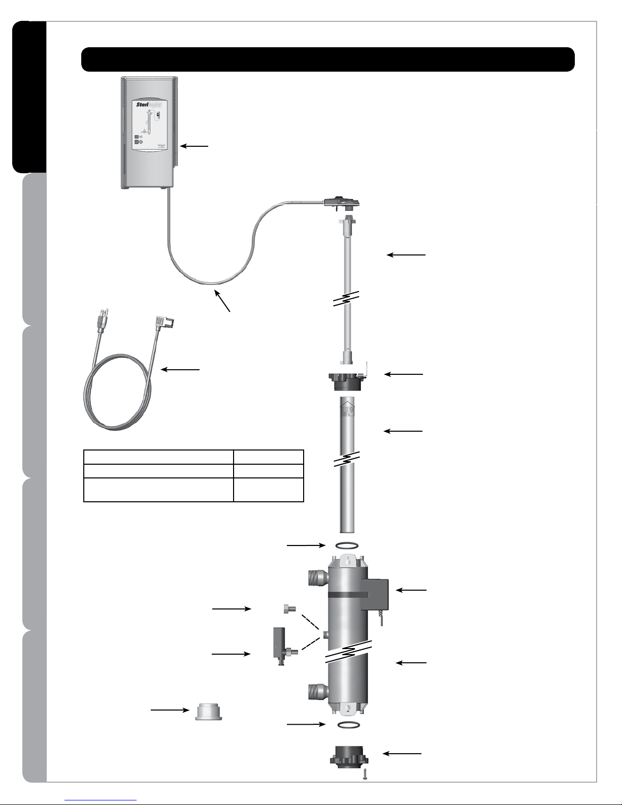
COMPONENTS
For replacement components please contact your
installer (listed on the front of this manual) or
contact VIQUA directly for a referral:
1 800 265 7246 (North America), 519 763 1032,
or info@viqua.com.
Power supply
SV50: Part #660023-R SM80: Part #660022-R S80: Part #660021-R
(power supply includes
lamp cord)
Lamp
SV50, SM80, S80:
Part #S37RL-AM
Lamp cord
Part #260174-R
Power cord
Part #602636 (120V)
Part #602637 (230V)
Accessory Part Number
2“ Solenoid Valve (option) 410898-R
CommCentre (option)
Remote Controller
270270-R
O-ring
Plug Kit
(Comes installed with
Basic Series chamber)
Sensor
(SV50 & SM80 only)
Part #440256-R
Top bolt & wireform
Part #602916 & 602896
Sleeve
SV50, SM80, S80: Part #QS-37
CoolTouchTM fan
Part #230438-R
Chamber
Sleeve removal
tool
Part #602988
Note: keep this tool with
system at all times.
4
O-ring
Bottom bolt (includes screw)
Part #603053
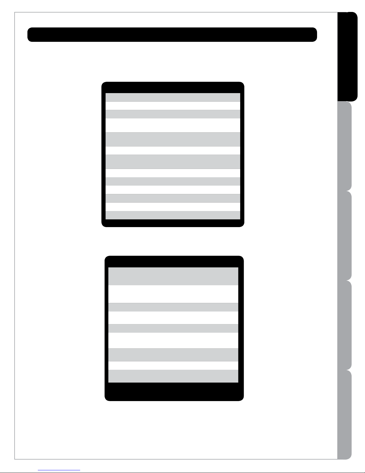
SPECIFICATIONS
General (All Models)
Operating Parameters
Maximum operating pressure 100 PSI (689 kPa)
Minimum operating pressure 4 PSI (27 kPa)
Maximum ambient air
temperature
Minimum ambient air
temperature
Maximum humidity 100%
Maximum hardness 120 ppm
Maximum iron 0.3 ppm
Minimum UVT 75%*
Installation Vertical ONLY
Other
Chamber material 316L SST
Rated service life of lamp 2 years
1040F (400C)
320F (00C)
(7 grains per gallon)
OVERVIEW
INSTALLATION WARRANTYMAINTENANCEOPERATION
* SV50 has a minimum UVT rating of 85%
SV50* SM80** S80**
Rated flow
dose of
30 mJ/cm
Rated flow
dose of
40 mJ/cm
Electrical
Voltage
Max. current 2.4 Amp 2.4 Amp 2.4 Amp
Max. power
consumption
Lamp power
consumption
Port Size
Inlet and
outlet
2
2
--
50 gpm
(189 lpm) -- --
100-240V
50-60Hz
230 Watts 230 Watts 230 Watts
200 Watts 200 Watts 200 Watts
2“ MNPT 2“ MNPT 2“ MNPT
up to 80 gpm
(265 lpm)
100-240V
50-60Hz
*Flow rates shown are at 85% UVT.
** Flow rates show are at 95% UVT.
up to 80 gpm
(265 lpm)
100-240V
50-60Hz
5
OVERVIEW
INSTALLATIONWARRANTY MAINTENANCE OPERATION
SPECIFICATIONS
SV50 SM80 S80
Color-coded plug and play
connections
Sensor with diagnostic test Yes Yes -CoolTouch fan Yes Yes Yes
Communications ports (two, RJ45) Yes Yes Yes
Solenoid valve Optional Optional Optional
Controls
Audible alarm mute button Yes Yes Yes
New lamp button Yes Yes Yes
Lamp age indicator Yes Yes Yes
Lamp operation indicator Yes Yes Yes
Power supply operation indicator Yes Yes Yes
Solenoid operation indicator Yes Yes Yes
Fan operation indicator Yes Yes Yes
Sensor reading indicator Yes Yes --
Yes Yes Yes
USEPA UVDGM 2006
(SV50 model only)
Other certifications
Yes -- --
6
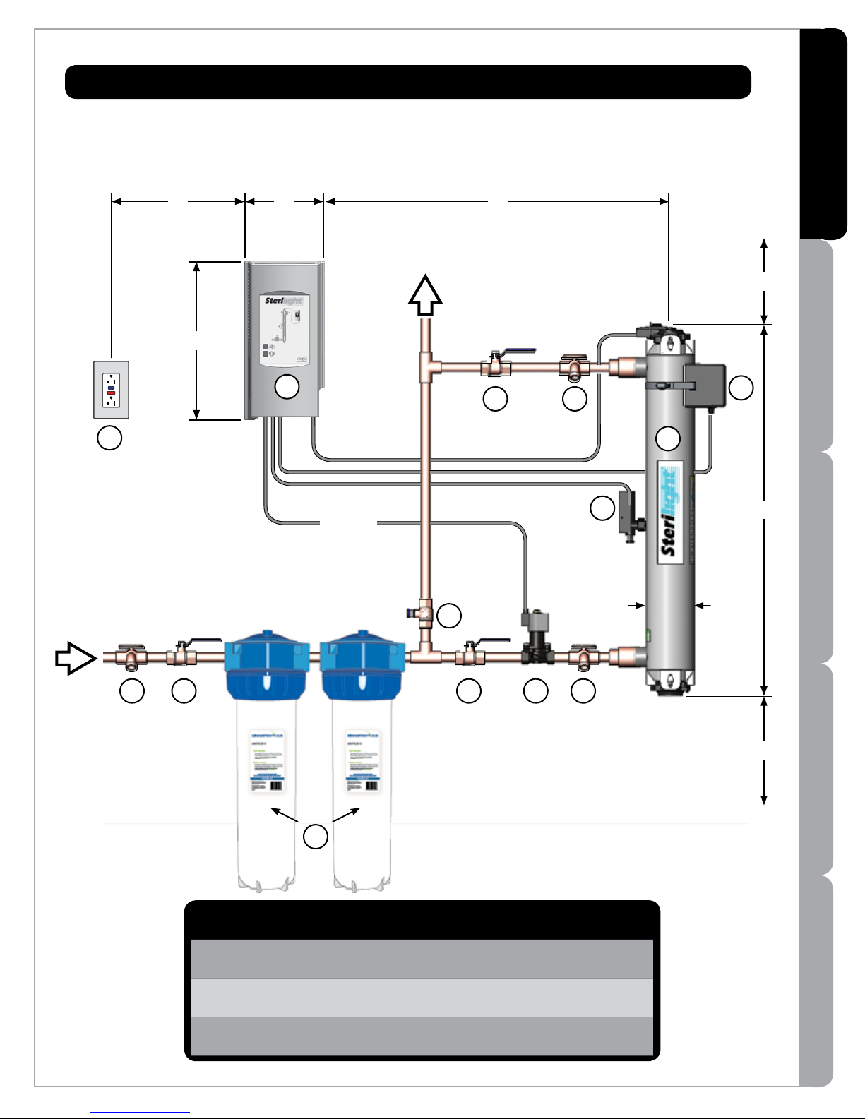
DIMENSIONS & LAYOUT
OVERVIEW
INSTALLATIONWARRANTY MAINTENANCE OPERATION
14
A B
C
13
72” (183cm
OUTLET
)
12
D
11
Clearance
for lamp
removal
L
10
9
8
L
INSTALLATION MAINTENANCEOPERATION
INLET
LModel
SV50 41"
(103cm)
SM80 41"
(103cm)
S80 41"
(103cm)
3
S
(min.)
12"
(30cm)4"(10cm)
12"
(30cm)4"(10cm)
12"
(30cm)4"(10cm)
4
5
61 2
Ø
7
Sampling and shut-off valves, fittings, and
pre-treatment equipment not included.
Ø D
(max.)
72"
(182cm)
72"
(182cm)
72"
(182cm)
6.5"
(16.5cm)
6.5"
(16.5cm)
6.5"
(16.5cm)
CBA
13"
(33cm)
13"
(33cm)
13"
(33cm)
(max.)
48"
(122cm)
48"
(122cm)
48"
(122cm)
S
7
OVERVIEW
INSTALLATIONWARRANTY MAINTENANCE OPERATION
Sample valve: Allows for sampling of raw water.
1
Shut-off valve: Required to allow maintenance of pre-treatment equipment.
2
Pre-treatment (illustrative only): For the UV system to operate effectively, the water should
3
meet certain water quality parameters, as outlined below. To meet these, pre-treatment of the
water may be required. Pre-treatment equipment must be installed BEFORE the UV chamber.
Pre-treatment systems can be comprised of one or more of the following elements: sediment
filters; carbon filters; iron removal systems; water softeners; cyst reduction filters, etc.
Water Quality Requirements:
Iron: < .3 PPM (.3 mg/L)
Hardness: < 120 PPM (7 Grains Per Gallon)
% UVT: > 75% (SM80, S80)
> 85% (SV50)
IMPORTANT:
A 5 micron (nominal) sediment filter must be installed
before the UV system and after any water softening equipment.
Bypass Shut-off valve: Bypass line and valve are optional. Intended to provide emergency water
4
supply in the event that the UV system is unavailable.
Shut-off valve: Required to allow maintenance of UV system.
5
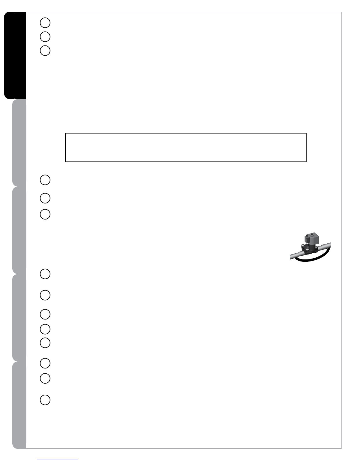
Solenoid valve: Optional piece of equipment supplied by VIQUA - a Trojan Technologies
6
Company. Allows water supply to be shut-off when proper disinfection cannot be assured (2“
Solenoid available).
Note: If the ground from your electrical panel is tied to your copper water lines, and you are using a
solenoid valve, installation of an approved ground strap is required. This ground strap will maintain
continuity between the lines that have been cut to install the solenoid. Check your local electrical
code for the correct clamp and cable size.
Sample valve: Allows for sampling of water entering UV chamber; necessary in order to confirm
7
water being treated is of adequate quality.
Sensor: Monitors UV output to ensure proper dose (UV exposure) is being provided. Unique test
8
function allows verification of sensor performance.
UV chamber: Provides disinfection of the water. MUST BE INSTALLED VERTICALLY.
9
TM
CoolTouch
10
Sample valve: Allows for sampling of water immediately following UV treatment; necessary in
11
fan: Removes excess heat from water in chamber during periods without water flow.
order to confirm proper operation of UV system.
Shut-off valve: Required to allow maintenance of UV system.
12
Power supply: Powers and controls the UV lamp and other devices. Provides human interface,
13
displaying information and allowing control inputs (such as muting the audible alarm).
Power source: Provides power to the power supply. For safety reasons the outlet must be
14
protected by a Ground Fault Circuit Interrupter (GFCI). NOTE: to protect the power supply, a
UL1449 certified (or equivalent) transient voltage surge suppressor is required.
8
WARRANTYMAINTENANCE
 Loading...